

AMT Datasouth 600 User Manual

Fastmark 600 Series
Barcode Label Printer
User’s Guide
Part No. 110462 Rev C

This page is blank.

IMPORTANT SAFETY INSTRUCTIONS
AND OTHER NOTICES
n This label printer complies with the requirements in Part 15 of FCC rules for a Class A
computing device. Operation of this equipment in a residential area may cause unacceptable
interface to radio and TV reception, requiring the operator to take whatever steps are
necessary to correct the interference.
n Place the printer on a flat, firm and solid surface.
n Do not place the printer near a heat source or near water.
n Refer to the specification label on the bottom of this printer and ensure that your power
source exactly meets these requirements.
n Do not open the printer during operation to avoid electrical shock.
n Do not attempt to disassemble this printer if it malfunctions.
n All rights are reserved. No part of this document may be reproduced or issued to third
parties in any form without the permission of the AMT Datasouth.
n The material in this document is provided for general information and is subject to change
without notice.
TRADEMARK CREDITS
Windows ®, MS-Word and MS-DOS are registered trademarks of Microsoft Corporation
PC ® is a registered trademark of International Business Machines
Centronics ® is a registered trademark of Centronics Corporation
COPYRIGHT NOTICES
© 2003 AMT Datasouth Corporation. All rights reserved.
© 2003 Adobe Systems Incorporated
© 1996-2003 The FreeType Project. All rights reserved.
© 1993 Symbol Technologies, Inc.
© 1990 United Parcel Service of America, Inc.
User Manual 1

CONVENTIONS
Some of the procedures in this guide contain special notices that highlight important information:
Note Indicate information that you should know to help your
printer run properly and efficiently.
Caution Indicate guidelines that, if not followed, can cause damage to
equipment.
Warning Indicate a situation where there may be a danger to you.
Important Indicate that the associated material needs to be done to
ensure proper printer operation.
The use of the term's right and left assume that you are looking at the
front of the printer.
COMPUTER SOFTWARE LICENSE AGREEMENT
This computer software, including display screens and all related materials, are confidential and
the exclusive property of AMT Datasouth Corporation. They are available for limited use, but
only pursuant to a written license agreement distributed with this computer software. This
computer software, including display screens and all related materials, shall not be copied,
reproduced, published or distributed, in whole or in part, in any medium, by any means, for any
purpose without the express written consent of AMT Datasouth Corporation.
© Copyright 2004 by AMT Datasouth Corporation
First Edition: November 2004
Second Edition: December 2005
2 User Manual

Table of Contents
IMPORTANT SAFETY INSTRUCTIONS AND OTHER NOTICES........................1
TABLE OF FIGURES.......................................................................................................4
INTRODUCTION .............................................................................................................5
MODEL OVERVIEW.......................................................................................................6
Models............................................................................................................................ 6
Model Features............................................................................................................... 7
UNPACKING AND INSPECTION.................................................................................8
INSTALLATION AND CONFIGURATION.................................................................9
Finding a Location for the Printer.................................................................................. 9
Printer Parts and Features..............................................................................................10
Connecting the Power Cord......................................................................................... 11
Connecting the Printer to Your Host............................................................................ 12
Loading the Ribbon.........................................................................................................13
Loading Media .................................................................................................................18
Loading Media with Peeler option............................................................................... 22
Loading Media with Pinch Roller Only option............................................................ 25
Loading Media into the Cutter Option......................................................................... 27
Calibrating the Media Sensor....................................................................................... 28
Printing the Configuration Label ................................................................................. 29
KEYPAD OPERATION .................................................................................................31
LED Description.......................................................................................................... 31
Key functions............................................................................................................... 32
Resetting the Printer to Factory Defaults..................................................................... 32
Windows Drivers..............................................................................................................33
Installing Windows Driver........................................................................................... 33
Setting the Printer’s Windows Parameters................................................................... 35
TROUBLESHOOTING AND MAINTENANCE.........................................................44
User Detected Errors.................................................................................................... 45
Peel and Present Sensing.............................................................................................. 48
Preventive Maintenance..................................................................................................49
Cleaning the Thermal Print Head (TPH) ..................................................................... 49
Cleaning the Platen Roller ........................................................................................... 50
Cleaning the paper sensor ............................................................................................ 50
Cleaning the Paper Compartment ................................................................................ 51
Appendix A: General Specifications..............................................................................52
Appendix B: INTERFACE SPECIFICATIONS..........................................................53
Serial Interface............................................................................................................. 53
Parallel (Centronics) Interface..................................................................................... 54
Appendix C: ASCII TABLE...........................................................................................55
Appendix D: Fonts, Bar Codes and Graphics...............................................................56
Printer Programming Language A, PPLA ................................................................... 56
PPLA Emulation Printer Control commands............................................................... 56
Printer Programming Language B, PPLB.................................................................... 59
PPLB Emulation Printer Control commands............................................................... 59
Appendix E: Parts List and Mechanical Drawings ......................................................61
User Manual 3

TABLE OF FIGURES
Figure 1 – Model and Serial Number Location ...............................................................................6
Figure 2 – Shipped with Printer.......................................................................................................8
Figure 3 – External Switches, Indicators and Connections ...........................................................10
Figure 4 – Internal Features...........................................................................................................10
Figure 5 – Power Connection ........................................................................................................11
Figure 6 – Communication Cable..................................................................................................12
Figure 7 – Top Media Cover Latches ............................................................................................13
Figure 8 – Print Head Latches .......................................................................................................13
Figure 9 – Ribbon Holder Notches and Ribbon Core Slots...........................................................14
Figure 10 – Supply Ribbon Installation.........................................................................................15
Figure 11 – Ribbon Take-Up Installation......................................................................................16
Figure 12 – Ribbon Installation .....................................................................................................16
Figure 13 – Print head Module Closed..........................................................................................17
Figure 14 – Top Media Cover Latches ..........................................................................................18
Figure 15 – Media Roll Installation...............................................................................................18
Figure 16 – Print Head Latches .....................................................................................................19
Figure 17 – Media Sensor and Guides...........................................................................................19
Figure 18 – Loading Media over Platen Roller..............................................................................20
Figure 19 – Positioning Media Guides and Sensor........................................................................20
Figure 20 – Print head Module Closed..........................................................................................21
Figure 21 – Label Removal for Peeler Option...............................................................................22
Figure 22 – Straight Edge and Peeler Latch ..................................................................................22
Figure 23 – Feeding into the Peeler Mechanism............................................................................23
Figure 24 – Backing Exit Position.................................................................................................23
Figure 25 – Peeler Option..............................................................................................................24
Figure 26 – Pinch Roller Latch......................................................................................................25
Figure 27 – Feeding into the Pinch Mechanism ............................................................................25
Figure 28 – Media Exit Position....................................................................................................26
Figure 29 – Pinch Roller Only Option...........................................................................................26
Figure 30 – Inserting Labels in the Cutter Option.........................................................................27
Figure 31 – Cutting Labels ............................................................................................................27
Figure 32 – Calibration of the Media.............................................................................................28
Figure 33 – Configuration Print Samples ......................................................................................30
Figure 34 – The Printer’s Front Panel............................................................................................31
Figure 35 – Print Head Location....................................................................................................49
Figure 36 – Platen Roller and Media Sensor .................................................................................50
Detail A..........................................................................................................................................66
Detail B..........................................................................................................................................67
Detail C..........................................................................................................................................68
Detail D..........................................................................................................................................69
4 User Manual

INTRODUCTION
The printer is a high-performance, low-cost Direct Thermal/Thermal Transfer labeling systems.
Its user-friendly design and affordable price set a new standard for the Desktop Label Printer in
retail, office and industrial applications.
The printer is designed with the most efficient memory management technology - True Speed and
prints at a speed of 1 to 6 inches per second. When bundled with its smart printer driver, the user
can easily print out bar codes, texts and graphics from any editing application (e.g. CodeSoft,
BarTender) under Windows 95/98/2000, and NT. All popular bar codes and fonts are resident in
the printer memory to handle versatile applications.
The solid designed mechanism allows quick and easy media (paper) and ribbon loading. The
optional Peel and Present, and Cutter provide alternatives of fan-fold label and continuous paper
handling.
This printer is a compact, highly integrated, high performance and high resolution on-site labeling
system.
The User’s Manual will help you understand basic operations of the printer such as set-up,
installation, configuration and maintenance. Before reading the manual you should first identify
your printer model. The printer model name is located on the back of the printer on its product
label.
User Manual 5
MODEL OVERVIEW
Models
The Fastmark 600 series supports several models and emulations:
Fastmark 602 (203 dpi – PPLA or PPLB emulations)
Fastmark 603 (300 dpi – PPLA or PPLB emulations)
Fastmark 612 (203 dpi – PPLZ emulation)
These models are similar in many ways. Throughout this manual instructions and illustrations
applying to a particular model will be labeled accordingly otherwise the instructions apply to all
models.
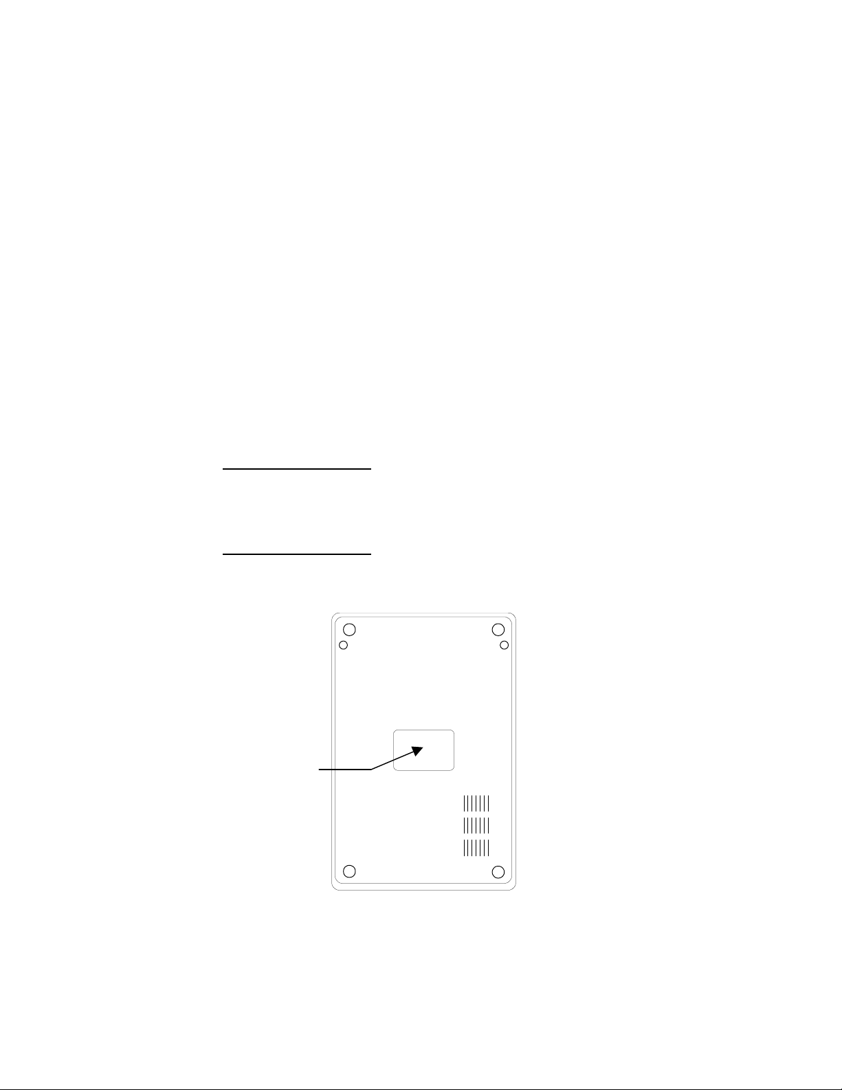
Note: The model number is printed on the compliance label attached to the bottom of the
printer. After unpacking please record the model number below for reference.
MODEL No:
SERIAL No:
Model No:
And
Serial No:
Figure 1 – Model and Serial Number Location
6 User Manual

Model Features
For detailed feature specifications, please refer to Appendix A. Below is a brief summary of
printer features:
Standard Features
q Popular Emulations. The printer offers multiple emulations. These emulations allow
the user to select one of three-printer languages thus allowing exceptional printing
abilities with flexible programming abilities. Because it is designed as both a printing
and multiple programming languages, it is extremely powerful, flexible, and efficient
compared to any other thermal printer language on the market today.
• PPLA emulation
• PPLB emulation
• PPLZ emulation
q Powerful Windows Drivers are included that enable use with Windows applications
q Serial and Parallel ports standard
q Clamshell design for simplified media and ribbon loading
q Reflective media detection sensor
q Ribbon out sensor
q Center Justified Media printing with removable media spindle.
q Rugged print mechanism with high impact ABS housing
User Manual 7
UNPACKING AND INSPECTION
This section is provided to assist you in removing the printer from the shipping container and
setting it up in the application environment. Inspect the shipping carton and contact the shipping
carrier directly to report any suspected damage.
1. With the shipping container in the upright position, remove the top foam packing
material.
2. Carefully, lift the printer straight up out of the box.
3. Remove the printer from the plastic bag and place the printer on a flat stable surface.
4. Remove the accessory kit and supplies.
5. Inspect the shipping container and the printer for any damage that may have occurred
during shipping.
Note:Save the box and all packing materials for future use, in the event the
printer needs to be shipped. Units returned for service in nonapproved packaging may void the warranty or increase repair costs
due to shipping damage.
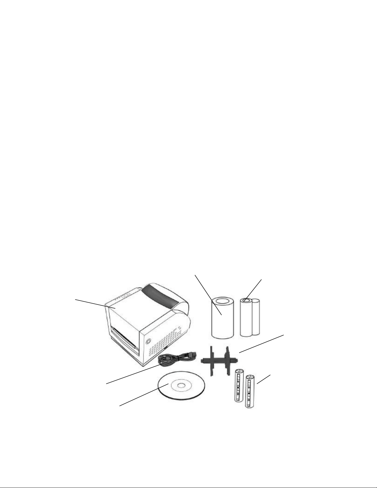
Verify that the printer box contains the following materials when unpacking:
a. Printer
b. Media Hanger
c. AC Power Cord
d. CD that contains User's manual, Windows drivers, and Printer Utilities
e. A sample media roll with a sample ribbon roll and a take-up ribbon core
f. Two Ribbon Core adapters for ribbon cores that are smaller than 4.325 inches in width.
Printer
Power Cord
CD
Sample Media
Figure 2 – Shipped with Printer
Sample Ribbon
Media Hanger
Ribbon Core Adapter
8 User Manual

INSTALLATION AND CONFIGURATION
Finding a Location for the Printer
Determine a suitable location for the printer with the following requirements:
• Find a flat stable surface with sufficient clearance to allow for interface cables and media
loading.
• The location should be near the host or terminal. Consider the distance between the host
and printer for the communication cable.
• The location should be free from excessive direct sunlight, temperature, humidity, dust,
dirt, and debris.
• The location should be near a grounded AC power receptacle wired in compliance with
local ordinances.
User Manual 9
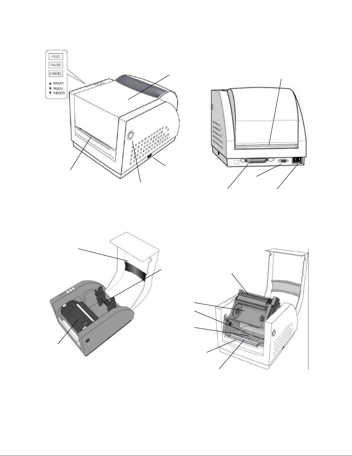
Printer Parts and Features
Media Out Slot
Top Cover
Power Switch
Serial Port
Cover Lock
Parallel Port
Figure 3 – External Switches, Indicators and Connections
External Media Slot
AC Power Port
Top Cover
Ribbon Take-up
Holder
Media Holder
Ribbon Supply Holder
Media Guides
Media Sensor
Media Present Bar
Thermal Printhead
Platen Roller
Figure 4 – Internal Features
10 User Manual
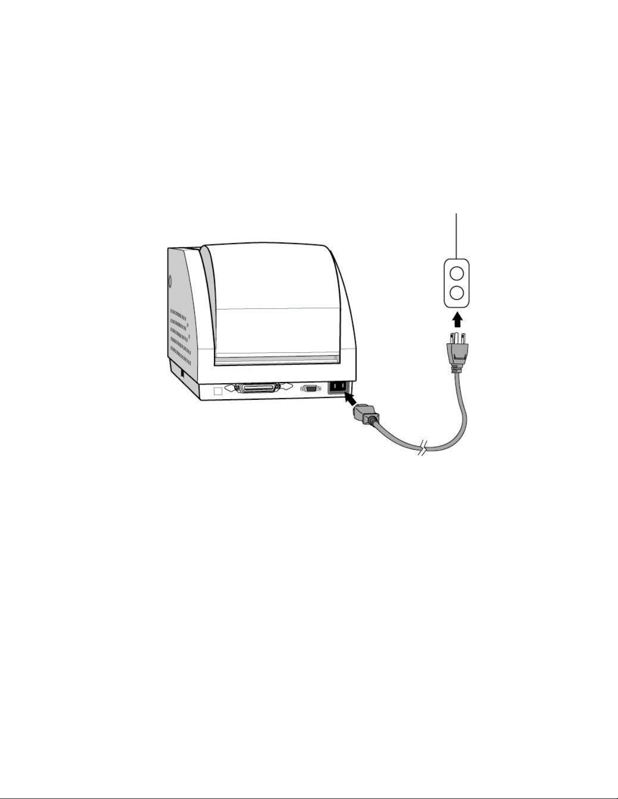
Connecting the Power Cord
1. Ensure the printer power switch is Off, “O”.
2. Connect the power plug to the back of the printer.
3. Connect AC power plug to a suitable AC source.
4. Connect either a Centronics Parallel or RS-232 Cable.
Figure 5 – Power Connection
User Manual 11
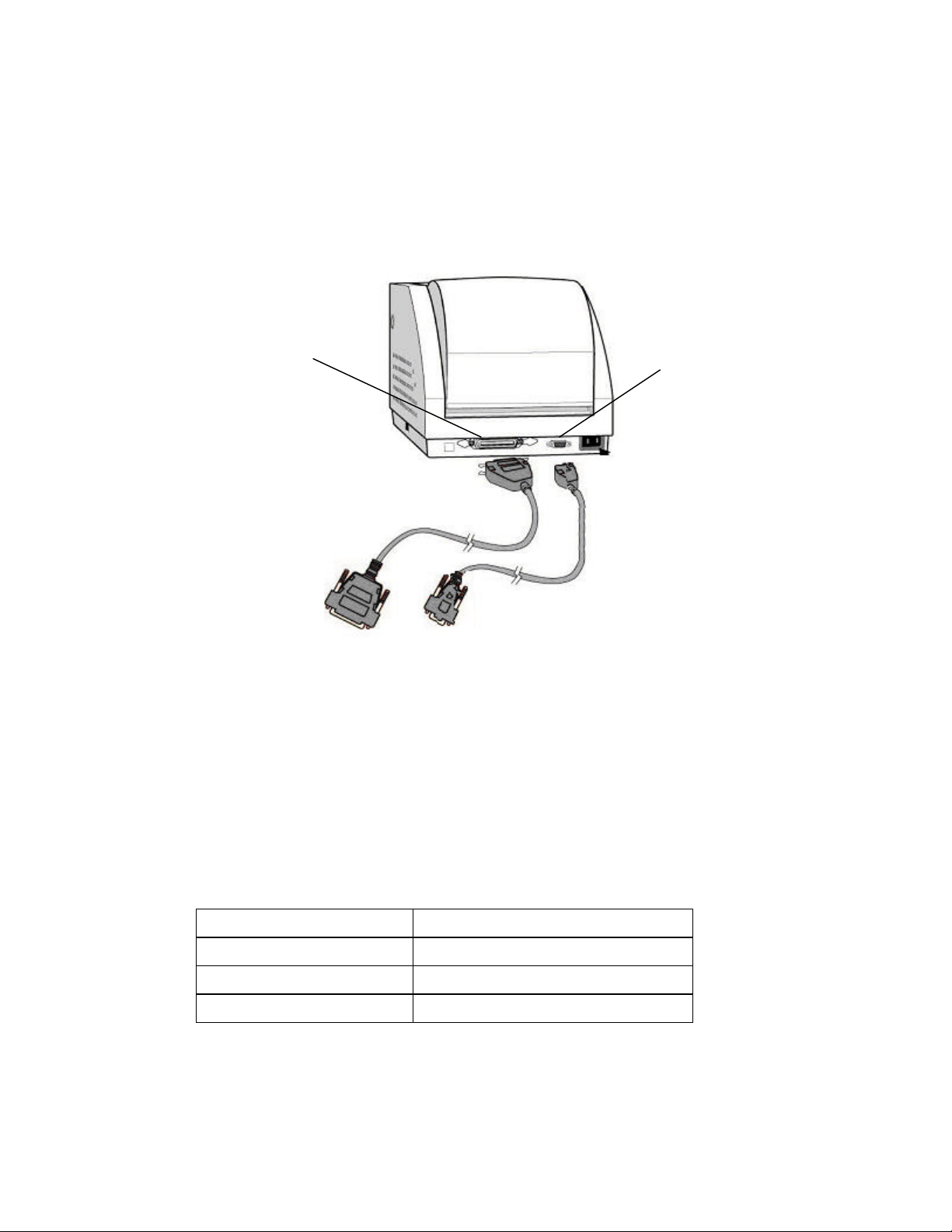
Connecting the Printer to Your Host
1. You can connect the printer with any standard Centronics cable to the parallel port of the
host computer or network print server.
2. Alternatively, you can connect the printer with a serial cable to the RS-232C port of your
computer or terminal. (For PC compatibles, the RS-232C port is COM1, COM2 or
COM3.)
Parallel Port
Serial Port
Figure 6 – Communication Cable
3. If you use the serial port with your own cable, refer to the Appendix B and check the pin
connection.
Caution: Pin 9 on the serial port is directly connected to +5 volts DC. Do not
connect this pin in your cable.
4. Be sure that the speed (baud rate) and protocols are the same between printer and host.
See your specific installed emulation for commands to set the Serial
Communications parameters.
Default serial port settings:
Speed (baud rate) 9600
Data format 1 start bit, 8 data bits and 1 stop bit
Parity None
Handshaking (Flow control) XON/XOFF and RTS/CTS
12 User Manual

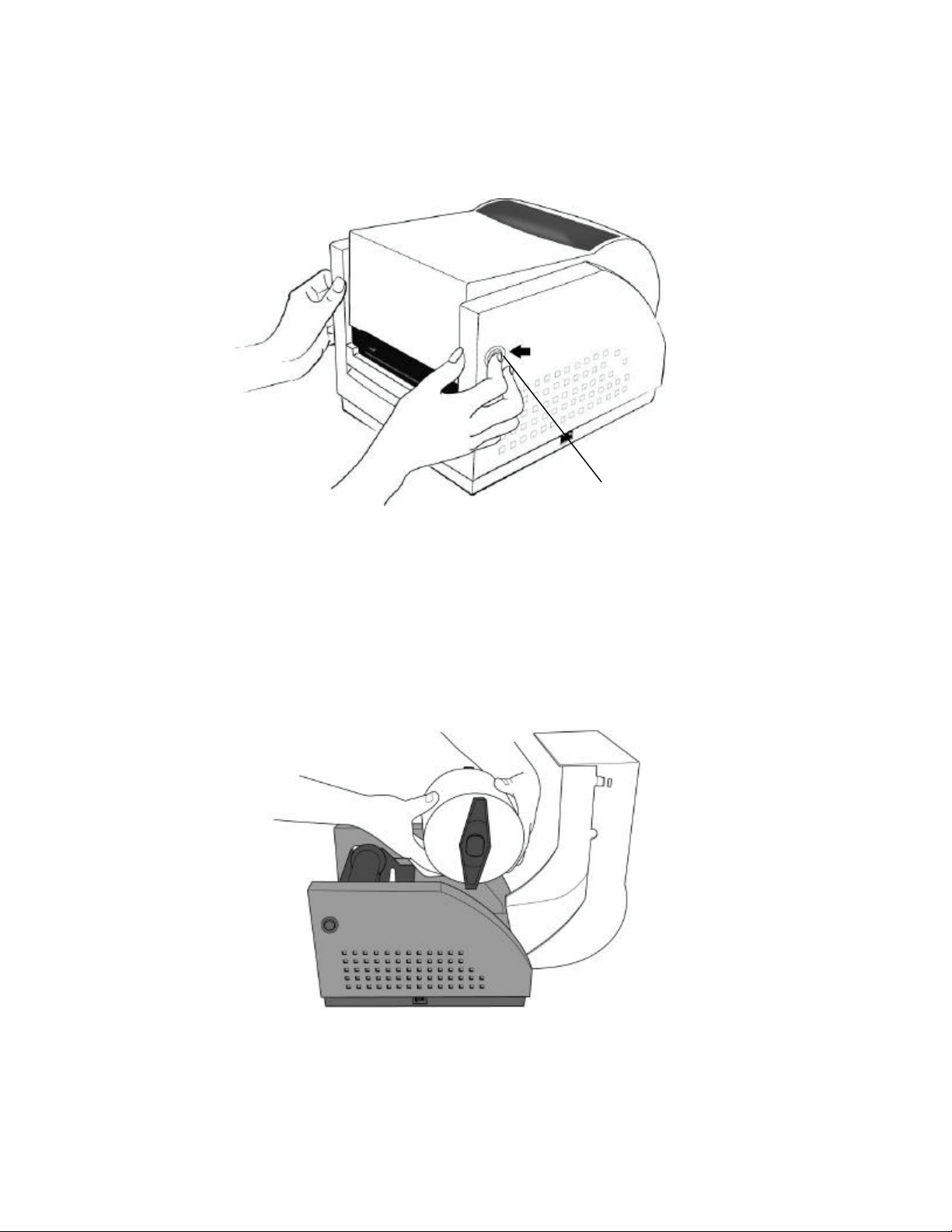
Loading the Ribbon
Cover Lock
Direct Thermal Media does not require the installation of a ribbon. Skip to the Loading Media
section.
Thermal Transfer media requires an installed ribbon. Follow the below instructions for ribbon
installation. Note: The media and the ribbon must be compatible. Also the print head
temperature setting may need to be adjusted (see emulation commands for heat adjustments).
1. Open the Top Media Access Cover by pressing in on both Cover locks (one on each side
of the printer) and lifting the top cover until it rests in the vertical position.
Figure 7 – Top Media Cover Latches
2. Press down on the two Print Head Latches (labeled PUSH) to unlock the print head
module.
Print Head Module
Print Head Release Latch
Print Head Release Latch
Figure 8 – Print Head Latches
User Manual 13
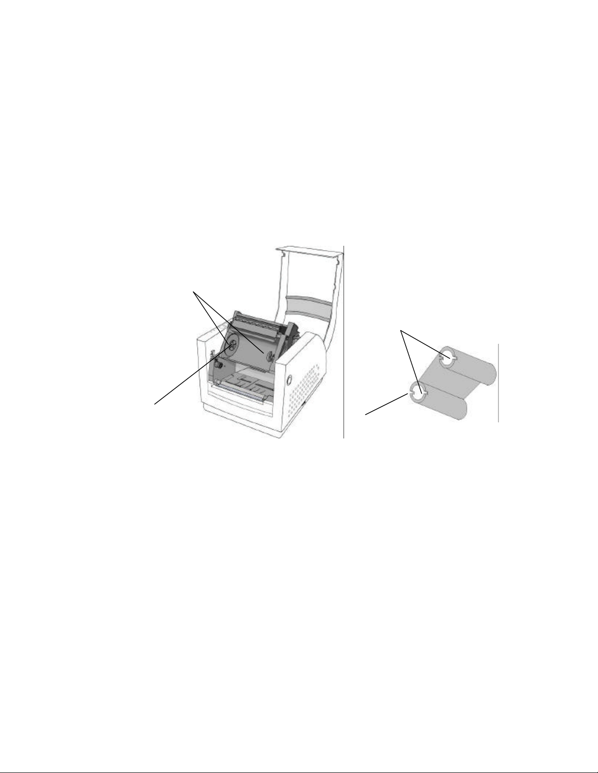
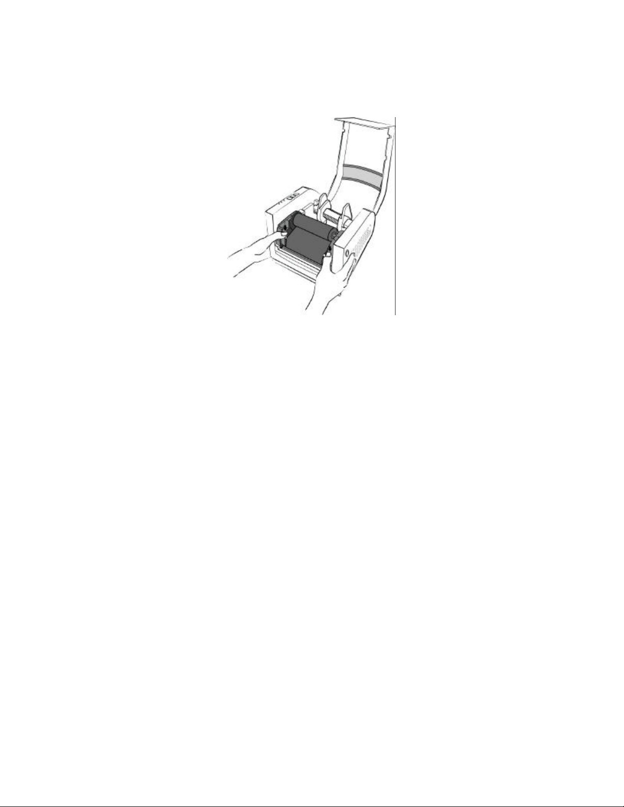
3. Rotate the Print Head Module to the vertical position.
4. Verify that the Ribbon Supply Core and the Ribbon Take-up Core have two slots on
the left side of the core 180-degree’s apart. If the width of the ribbon is less than the
minimum core width or if no slots are present, insert one of the supplied Ribbon Core
Adapters into each ribbon core.
5. The Slots in the Ribbon Core should mate to the Notches in the Left Ribbon Supply
Holder and the Left Take-Up Holder. If using the Ribbon Core Adapter, the adapter’s
notches will mate with the slots in the Ribbon Holders.
Note: The notches are the drive mechanism and the ribbon out reporting for the ribbon. If the
slots for the Ribbon Core are not correct, contact your ribbon supplier to obtain the correct
ribbon. If you need the Ribbon Core Adapter, contact your printer supplier.
Ribbon Supply Holder
Ribbon Supply Core and
Take-up Core
Ribbon Notch Location
Core Slots
Figure 9 – Ribbon Holder Notches and Ribbon Core Slots
14 User Manual
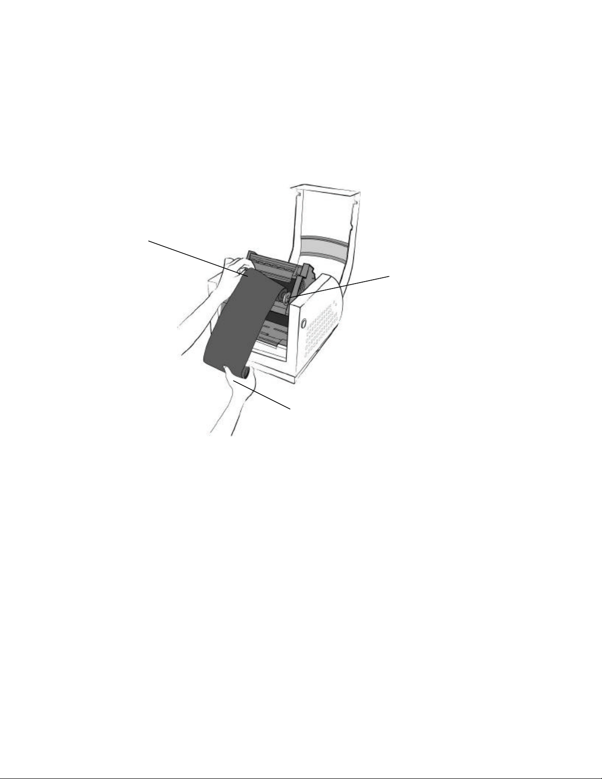
6. Unwrap the Ribbon Supply Roll and prepare to place it into the Supply Holder area of
the print head module. Make sure that the Ribbon is coming off the Top of the Ribbon
Roll and to the front of the printer (Ribbon should be a wound-in type). See Supply
Ribbon Installation figure below.
7. Insert the Ribbon Supply Core into the Ribbon Supply Area by first compressing the
right side spring and snapping the left side of supply core into the left side of the notched
wheel. Make sure that the slots in left side of the core mate with the notches on the left
side ribbon drive wheel.
Ribbon Supply Roll
Right Side Spring Holder
Ribbon Take-Up Roll
Figure 10 – Supply Ribbon Installation
User Manual 15
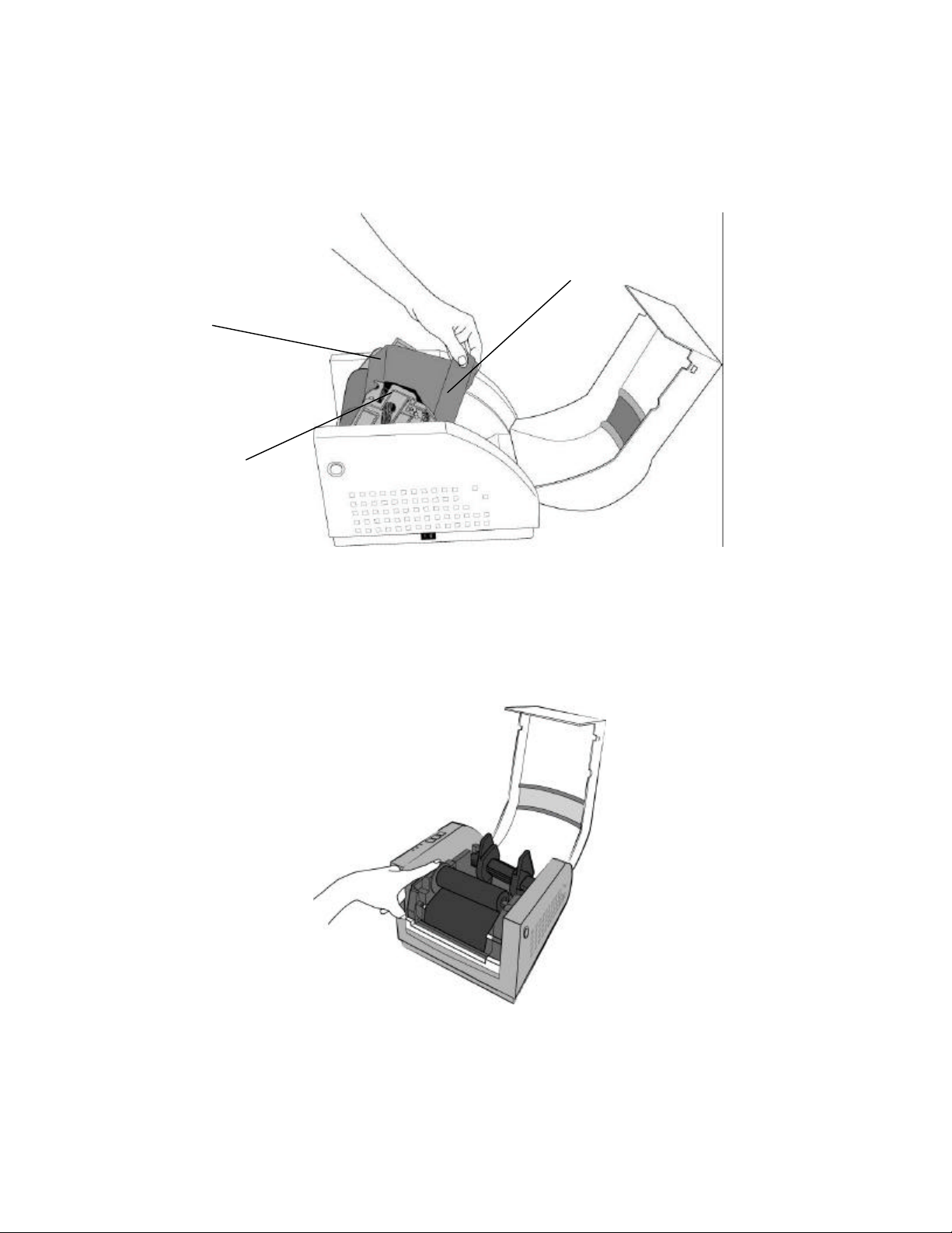
8. Loop the ribbon over the Print Head Module. Insert the Take-up Core into the Take-Up
Area by first compressing the right side spring and snapping the left side of take-up core
into the left side of the notched wheel. Make sure that the slots in left side of the core
mate with the notches on the left side ribbon drive wheel.
Ink Side of the Ribbon
Print Head Module
Take-Up Core
Figure 11 – Ribbon Take-Up Installation
9. To remove any slack in the ribbon, manually rotate the Take-up Core Wheel until the
ribbon from the Supply Holder is snug around the Print head Module and onto the Take-
up Core.
Figure 12 – Ribbon Installation
16 User Manual
10. Close and latch the print head module. Be sure to press firmly on both sides so that
both latches clink into place. If either latch is not clicked into place it will cause the
media to not feed properly or print light.
Figure 13 – Print head Module Closed
Note: The printer must be set to the Thermal Transfer mode to ensure the end of ribbon is
detected. Refer to the section Emulation Commands for instructions on how to change the
Media Type feature.
User Manual 17
Loading Media
Cover Lock
1. Open the Top Media Access Cover by pressing in on both Cover locks (one on each side of
the printer) and lifting the top cover until it rests in the vertical position.
Figure 14 – Top Media Cover Latches
2. Remove the Media Hanger from the printer.
3. Remove one side of the Guides from the Media Hanger and slide the Media Roll onto the
Media Hanger, then reinstall the removed Guide.
4. Place the Media Hanger with roll of media into the appropriate slots on the printer and
centered the media in the printer.
Figure 15 – Media Roll Installation
18 User Manual
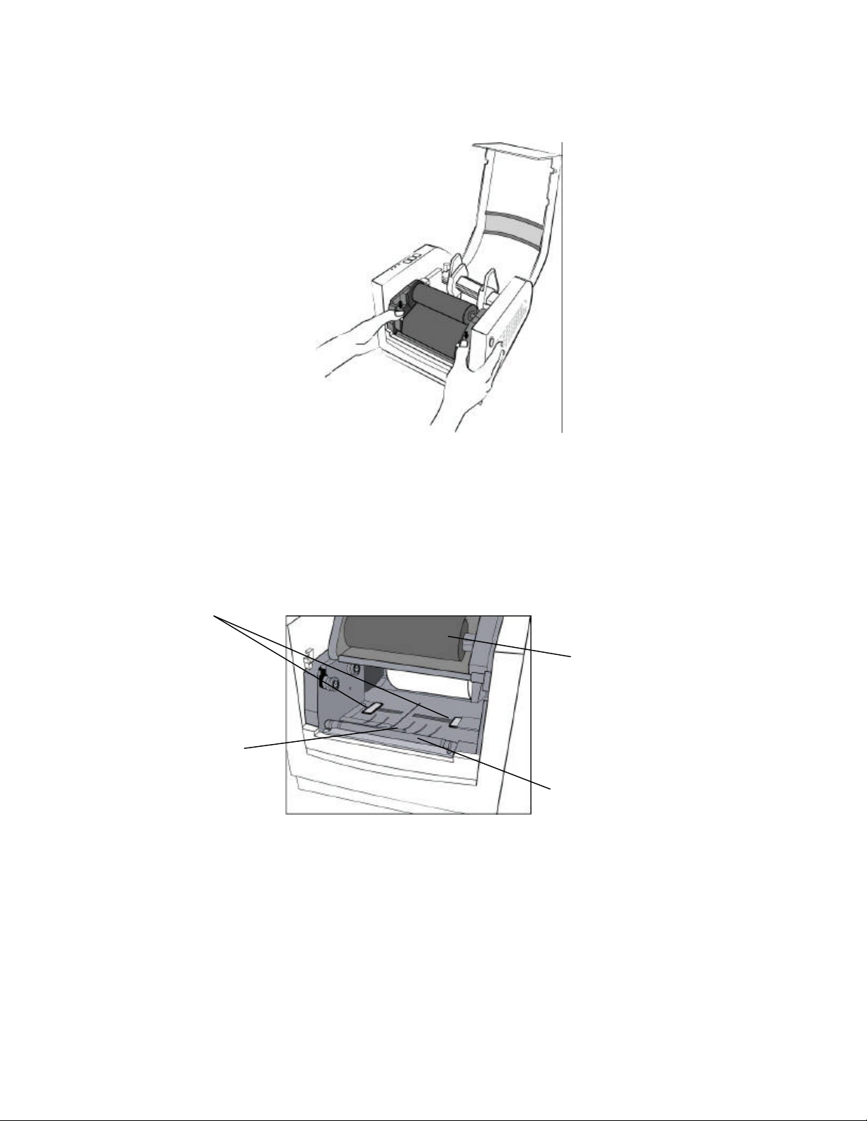
5. Press down on the two Print Head Latches to unlock the print head module.
Figure 16 – Print Head Latches
6. Rotate the Print Head Module to the vertical position.
7. Spread the Media Guides to their full open position.
Media Guides
Media Sensor
Figure 17 – Media Sensor and Guides
Print Head Module
Platen Roller
User Manual 19
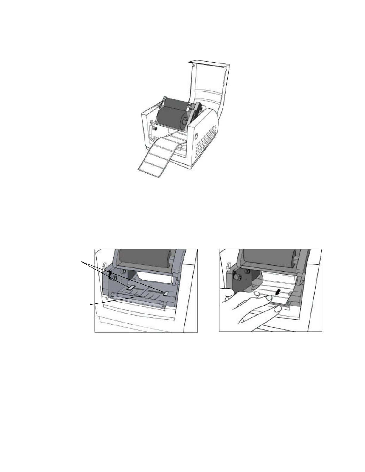
8. With the printing side up, feed the Media off the Media Roll under the Print Head
Module and over the platen.
Figure 18 – Loading Media over Platen Roller
9. Position the Media Sensor to the desired location.
To position the Media Sensor examine the back of the Media Stock. As the media is
pulled through the printer position the sensor to avoid holes or preprinted information on
the back of the stock. These may cause incorrect top of form alignment. Typical media
stock backing is blank, therefore position the sensor in the middle of the stock.
Media Guides
Media Sensor
Figure 19 – Positioning Media Guides and Sensor
10. Close the Right and Left Media Guides until the Media Stock is under the “U” shaped
guides. This will keep the stock from going side to side.
Note: The Right and Left Media Guides are ‘U’ shaped parts that are located at the bottom of the
paper path. Both Guides move together to hold the stock in the Center of the printer.
If the printer has the Peeler, Pinch or Cutter options go to either the appropriate Loading Media
sections.
20 User Manual
 Loading...