

AMT Datasouth 5106 User Manual

CodeWriter 5106
Technical Reference
PART NO. 108741 Rev. A

AMT Datasouth Corp.
Corporate Headquarters
4765 Calle Quetzal
Camarillo, CA 93012
(805) 388-5799 PH
(805) 484-5282 FX
Charlotte Operation
4216 Stuart Andrew Blvd.
Charlotte, NC 28217
(704) 523-8500 PH
(704) 525 6104 FX
www.amtdatasouth.com
AMT Datasouth International
Unit B, Pinnacle 15
Gowerton Rd, Brackmills
Northampton, NN4 7BW
England
+44 1604 763394 PH
+44 1604 760661 FX

AMT Datasouth CodeWriter 5106 Disclaimer of
Warranties
IMPORTANT!
READ THIS FIRST; IT LIMITS OUR LIABILITY
SOFTWARE
All software is licensed “as is” without warranty of any kind, either expressed or implied,
including but not limited to the implied warranties of merchantability and fitness for a
particular purpose. AMT Datasouth Corp. and it’s authorized sales agent have no
liability, loss, or damage caused, or alleged to have been caused directly or indirectly by
the software system (hardware, software, User’s Guide, User’s Manual, and labels), nor
for indirect, special, or consequential damages. In no event will AMT Datasouth Corp.
be liable to you for any damages, including any lost profits, savings, or other incidental or
consequential damages arising out of the use or inability to use any program produced by
AMT Datasouth Corp. or any authorized dealer advised of the possibility of such
damages occurring. No person has the authority to modify such limitations, unless
obtained in writing and signed by a corporate officer at AMT Datasouth Corp.
Acceptance of software is conditional on the acceptance of this disclaimer. Use of the
hardware/software constitutes acceptance of this disclaimer.
EXTENDED SOFTWARE SUPPORT
AMT Datasouth Corp. provides telephone support and maintenance following delivery
of your software/hardware system. Check with AMT Datasouth Corp. for details and
current pricing on extended maintenance support.
HARDWARE
Hardware provided with your system is warranted to be free from defects in
workmanship and performance by the respective manufacturers. Refer to the AMT
Datasouth Service Policy and Pricing Handbook for warranty information. Call customer
support at (800) 476-2450 for return authorization. CodeWriter is a trademark of AMT
Datasouth Corp. All other brand and product names are trademarks or registered
trademarks of their respective companies.
LABELS, TAGS AND RIBBONS
Only previously authorized label and ribbon material may be used in this printer. Due to
variations in label and ribbon quality, use of unauthorized material may void the
warranty. Check with your AMT Datasouth Dealer for a list of authorized suppliers. In
the event you require a special material for your labels, tags or ribbons you may send
samples to the manufacturer for authorization.

COPYRIGHT NOTICE
This guide is copyrighted. All rights reserved. This guide may not, in whole or part, be
reproduced, translated, stored in a retrieval system or transmitted in any forms or by any
means, electronic, mechanical, photographic, or otherwise, without the prior written
consent of AMT Datasouth Corp.

The following expressions are used to explain keyboard
operations:
• Depress [SHIFT] means: depress the [SHIFT] key.
• Depress [1] [4] [1] or [1, 4, 1] means: depress the [1], [4], then the [1] keys.
• Depress [SHIFT] + [1, 4, 1] or [R + 1, 4, 1] means: while depressing the [SHIFT]
key, depress the [1], [4], then the [1] keys.
The following abbreviations are used throughout this
documentation:
• mm = millimeter • cm = centimeter
• um = micrometer • KB = kilobyte
• MB = megabyte • ns = nanoseconds
• A = ampere • MHz = megahertz
• mV = millivolt • Vac = voltage alternating
current
• Vdc = voltage direct current • h/s screw = hexagon socket
screw


Table of Contents
1.0 GENERAL INFORMATION ...........................................................................................................................1
1.1 Features ............................................................................................................................................................ 1
1.2 5106 Overall Dimensions .............................................................................................................................2
1.3 Ribbon Specifications...................................................................................................................................2
2.0 INITIAL SETUP.................................................................................................................................................3
2.1 Assembly and Setup Procedure ...................................................................................................................3
2.2 Selection of Media Output Mode................................................................................................................3
2.3 Parameter Setting Mode................................................................................................................................4
2.4 Parameter Tree Version 1.90........................................................................................................................5
3.0 LOADING INK RIBBON AND LABEL ROLL..........................................................................................6
4.0 ADJUSTMENTS................................................................................................................................................8
4.1 Thermal Head Repla cement .........................................................................................................................8
4.2 Changing the Direction of the Take-up Roller ..........................................................................................9
4.3 Thermal Head Positioning..........................................................................................................................10
5.0 MECHANICAL ADJUSTMENTS TO THE THERMAL HEAD..........................................................11
6.0 RIBBON.............................................................................................................................................................17
6.1 Ribbon Adjustment......................................................................................................................................17
6.2 Running Condition.......................................................................................................................................19
7.0 SENSORS..........................................................................................................................................................21
8.0 SENSITIVITY ADJUSTMENT....................................................................................................................22
9.0 ELECTRICAL CIRCUITRY..........................................................................................................................24
10.0 EXTERNAL CONNECTOR AND PIN ASSIGNMENTS.......................................................................25
11.0 VOLTAGE CHECK AND ADJUSTMENT...............................................................................................26
12.0 MAIN PCB BOARD........................................................................................................................................27
13.0 TAKE-UP MOTOR CONNECTORS...........................................................................................................28
Table of Figures
Figure 1. Overall Dimensions........................................................................................................................................2
Figure 2. Ribbon Dimensions........................................................................................................................................2
Figure 3: Loading Ribbon and Label Roll...................................................................................................................6
Figure 4. Thermal Head Replacement..........................................................................................................................8
Figure 5. Thermal Head Block.....................................................................................................................................10
Figure 6. Mechanical Adjustment...............................................................................................................................11
Figure 7. Hinge of Thermal Head Lever....................................................................................................................12
Figure 8. Thermal Head Alignment ............................................................................................................................ 13
Figure 9. Thermal Head Positioning...........................................................................................................................14
Figure 10. Head Positioning.........................................................................................................................................15
Figure 11. Incline Checking of the Thermal Head...................................................................................................16
Figure 12. Ribbon Running Condition ....................................................................................................................... 18
Figure 13. Wrinkle On Ribbon .................................................................................................................................... 19
Figure 14. Ribbon Application Adjustment .............................................................................................................. 20
Figure 15. Location of Sensors and Switch...............................................................................................................21


1.0 GENERAL INFORMATION
The 5106 is a general thermal printer which offers universal printing, including various
types of barcodes. High speed and high dot density print is available which allows you to
create any label format desired through computer software generated code.
1.1 Features
• Both On-line/Off-line operation modes available
• Thermal direct and thermal transfer printing systems are adopted.
• Extremely high dot density – 203 dots/inch or 8 dots/mm.
• High speed printing – 6.00 inches/sec or 150 mm/sec.
• Most industry standard symbologies supported.
• Built-in internal and external rewind mechanism.
• Wide print width – 5.04 inches or 128 mm
1
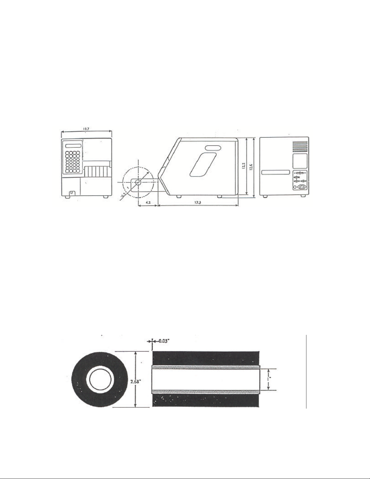
1.2 5106 Overall Dimensions
• Length: 17.3 inches/440 millimeters
• Extended Rewind: (On center from front) 4.2 inches/107 millimeters
• Height: 12.6 inches/320 millimeters
• Width: 10.7 inches/273 millimeters
Figure 1. Overall Dimensions
1.3 Ribbon Specifications
• Length: 984 feet/300 meters
• Ribbon Leader (Clear): 12 inches/300 millimeters
• Ribbon Trailer (Mirror coating): 6 inches/150 millimeters
• Ink Side: Outside
Figure 2. Ribbon Dimensions
2

2.0 INITIAL SETUP
2.1 Assembly and Setup Procedure
The 5106 printer provides various output modes which will correspond to the various
customer requirements. Assemble and setup the printer according to the customer
application.
2.2 Selection of Media Output Mode
Output Mode under printer parameters provides the selection. Refer to the next section
when choosing parameter settings.
Output Mode
Non-spooled
Spooled
Presentation
Optional Cutter
Function
The label is issued with the liner.
(The printer does not rewind the
label and liner). Attaching the
Tear Bar instead of the
Presentation Sensor, the label
and liner can then be torn off
together (manually)
The label is issued with liner, and
the printer rewinds both the
issued label and liner on the
Take-Up Roller (as an external
rewinder).
The labels are issued with liner
and peeled off at the dispenser
and present Label Holder. The
printer rewinds only the liner,
inside the printer.
The labels are issued with liner
and separated in the specified
timing by the Optional Cutter.
Remark
Remove label Presentation
Sensor and then attach the
Tear Bar.
Position the Take-Up
Roller on the outside of the
printer (as an external
rewinder).
Set the Take-Up Roller on
the inside of the printer.
Optional cutter mechanism
is required.
3
 Loading...