

AMT Datasouth 400 User Manual

PAL
Fastmark 400 Series with
TM
Print and Program Language
Barcode Label Printer
User’s Guide
Part No. 110039 A

AMT Datasouth Corp.
Corporate Headquarters
4765 Calle Quetzal
Camarillo, CA 93012
(805) 388-5799 PH
(805) 484-5282 FX
Charlotte Operation
4216 Stuart Andrew Blvd.
Charlotte, NC 28217
(704) 523-8500 PH
(704) 525 6104 FX
www.amtdatasouth.com
AMT Datasouth International
Unit B, Pinnacle 15
Gowerton Rd, Brackmills
Northampton, NN4 7BW
England
+44 1604 763394 PH
+44 1604 760661 FX

IMPORTANT SAFETY INSTRUCTIONS
AND OTHER NOTICES
! This label printer complies with the requirements in Part 15 of FCC rules for a Class A
computing device. Operation of this equipment in a residential area may cause unacceptable
interface to radio and TV reception, requiring the operator to take whatever steps are
necessary to correct the interference.
! Place the printer on a flat, firm and solid surface.
! Do not place the printer near a heat source or near water.
! Refer to the specification label on the bottom of this printer and ensure that your power
source exactly meets these requirements.
! Do not open the printer during operation to avoid electrical shock.
! Do not attempt to disassemble this printer if it malfunctions.
! All rights are reserved. No part of this document may be reproduced or issued to third
parties in any form without the permission of AMT Datasouth.
! The material in this document is provided for general information and is sub ject to ch ang e
without notice.
User's Guide 3

TRADEMARK CREDITS
Windows ® , MS-Word and MS-DOS are registered trademarks of Microsoft Corporation
PC ® is a registered trademark of International Business Machines
Centronics ® is a registered trademark of Centronics Corporation
PAL is a registered trademark of AMT Datasouth Corporation
COPYRIGHT NOTICES
© 2004 AMT Datasouth Corp. All rights reserved.
© 2003 Adobe Systems Incorporated
© 1996-2003 The FreeType Project. All rights reserved.
© 1993 Symbol Technologies, Inc.
© 1990 United Parcel Service of America, Inc.
COMPUTER SOFTWARE LICENSE AGREEMENT
This computer software, including display screens and all related materials, are confidential and
the exclusive property of AMT Datasouth Corp. They are available for limited use, but only
pursuant to a written license agreement distributed with this computer software. This computer
software, including display screens and all related materials, shall not be copied, reproduced,
published or distributed, in whole or in part, in any medium, by any means, for any purpose
without the express written consent of AMT Datasouth Corp.
© COPYRIGHT AMT Datasouth Corp. 2004 ALL RIGHTS RESERVED.
User's Guide 4

CONVENTIONS
Some of the procedures in this guide contain special notices that highlight important information:
Note Indicate information that you should know to help your
printer run properly and efficiently.
Caution Indicate guidelines that, if not followed, can cause damage to
equipment.
Warning Indicate a situation where there may be a danger to you.
Important Indicate that the associated material needs to be done to
ensure proper printer operation.
The use of the term's right and left assume that you are looking at the
front of the printer.
TECHNICAL SUPPORT
Please contact your local dealer first for technical support. Your dealer is knowledgeable about
driver installation, application software and general printer operation. If you still need factory
technical support after contacting your dealer, you may mail any problems through the E-mail
account, “www.amtdatasouth.com”. You can also get the most updated driver or application
from the web site “http://www.amtdatasouth.com”.
© Copyright 2004 by AMT Datasouth Corporation
First Edition: January 2004
User's Guide 5

Table of Contents
TABLE OF FIGURES.......................................................................................................8
INTRODUCTION..............................................................................................................9
MODEL OVERVIEW.....................................................................................................10
Models..........................................................................................................................10
Model Features............................................................................................................. 11
PALTM PRINT AND PROGRAM OVERVIEW..........................................................12
Traditional Printing...................................................................................................... 12
Legacy Data Stream Interpretation .............................................................................. 13
UNPACKING AND INSPECTION...............................................................................14
INSTALLATION AND CONFIGURATION...............................................................15
Finding a Location for the Printer................................................................................ 15
Connecting the Power Cord......................................................................................... 16
Connecting the Printer to Your Host............................................................................ 17
Loading the Ribbon...................................................................................................... 18
Loading Media............................................................................................................. 21
Loading Media when Peel and Present Option is Installed.......................................... 23
Calibrating Media Sensors........................................................................................... 24
Printing the Configuration Label ................................................................................. 25
KEYPAD OPERATION .................................................................................................26
LED Description .......................................................................................................... 26
FEED Key Operation................................................................................................... 27
Power up key functions................................................................................................ 27
Feature Management Mode.......................................................................................... 28
Setup Feature and Value List....................................................................................... 29
PALTM PRINT LANGUAGE INTRODUCTION.........................................................33
Smooth Scalable Fonts................................................................................................. 34
Supported Bar Codes.................................................................................................... 34
PALTM Print and Program Label Tutorial.................................................................... 36
PALTM Print and Program Coordinate System ............................................................ 38
INTRODUCTION TO PALTM ADVANCED TOPICS................................................43
Advanced Overview..................................................................................................... 43
PALTM Print and Program Language Features............................................................. 44
Sample Demo Files...................................................................................................... 45
Example of a Procedure defined in PALTM.................................................................. 46
Example of calling a Procedure from a host application ............................................. 46
Demo Label showing use of Print Utility Procedures.................................................. 47
Example of How to Define Label Formats .................................................................. 48
Example of calling Label Format from Host Application ........................................... 49
WINDOWS PRINTER DRIVER...................................................................................50
Windows 2000 Driver Installation............................................................................... 50
Windows XP Driver Installation.................................................................................. 54
Windows NT/9x Driver Installation............................................................................. 58
Using the Windows Driver To Produce PALTM Print Command Examples............... 62
User's Guide 6

TROUBLESHOOTING AND MAINTENANCE.........................................................63
Printer Detected Errors................................................................................................. 63
User Detected Errors.................................................................................................... 65
Preventive Maintenance............................................................................................... 66
Appendix A: GENERAL SPECIFICATIONS..............................................................69
Appendix B: INTERFACE SPECIFICATIONS..........................................................70
Serial Interface............................................................................................................. 70
Parallel (Centronics) Interface ..................................................................................... 71
Auto Interface Select.................................................................................................... 71
Appendix C: ASCII TABLE...........................................................................................72
Appendix D: SELF TEST PRINT SAMPLE................................................................73
Appendix E: HIDDEN SETUP FEATURES.................................................................74
Hidden Setup Feature and Value List .......................................................................... 74
Appendix F: UPDATING PRINTER FIRMWARE.....................................................76
Boot Mode Feature and Value List.............................................................................. 78
User's Guide 7

TABLE OF FIGURES
Figure 1 – Model and Serial Number Location............................................................................. 10
Figure 2 – Traditional Printing...................................................................................................... 12
Figure 3 – Legacy Data stream Interpretation............................................................................... 13
Figure 4 – Shipped with Printer .................................................................................................... 14
Figure 5 – Switches, Indicators and Connections ......................................................................... 15
Figure 6 – Power Connection........................................................................................................ 16
Figure 7 – Communication Cable..................................................................................................17
Figure 8 – Print Head Latches....................................................................................................... 18
Figure 9 – Ribbon Holder Notch Location.................................................................................... 19
Figure 10 – Ribbon Loading.......................................................................................................... 20
Figure 11 – Open Media Access Cover......................................................................................... 21
Figure 12 – Media Spindle and Retainer Disk .............................................................................. 21
Figure 13 – Loading Media........................................................................................................... 22
Figure 14 – Loading Media - Peal and Present ............................................................................. 23
Figure 15 – Configuration Print Sample ....................................................................................... 25
Figure 16 – Fastmark 400 Series Front Panel ............................................................................... 26
Figure 17 – FeatureMan Program..................................................................................................28
Figure 18 – Changing Features ..................................................................................................... 29
Figure 19 – Changing Feature Values........................................................................................... 29
Figure 20 – Print Head Location................................................................................................... 66
Figure 21 – Platen Roller............................................................................................................... 67
Figure 22 – Paper Compartment and Paper Sensor....................................................................... 68
User's Guide 8

INTRODUCTION
The FM412 / FM403 are high-performance, low-cost Direct Thermal/Thermal Trans fer label ing
printers featuring the PAL
TM
PAL
Print and Program language is an interpretive page description language that allows
printers to move beyond the role of normal printers. In addition to supporting traditional text, bar
code, and graphics print sequences common to other printers, PAL
also serves as a general purpose programming language. This combination of sequence based
printing commands and programming ability allows printers to provide unique solutions such as:
" Intelligently read and interpret legacy data streams without host system programming
changes. Add or replace printers without changing the data streams. For example, this
tremendous flexibility permits changing from dot matrix text or card embosser’s to high
quality thermal printing with bar codes without changing the original data from the
host.
" Store label formats and databases in the printer.
" Store PAL
TM
don't require a host or PC connection.
" Create and store PAL
system goes down.
" Read data from an optional keyboard, scanner, scale, etc. and combine this data with
fixed formats to create powerful labeling solutions.
" Perform math calculations and perform logical decisions within the printer.
TM
Print and Program language.
TM
Print and Program language
programs in the printer to create powerful stand-alone applications that
TM
programs in the printer, which allow it to operate even if the host
TM
PAL
Print and Program presents many exciting possibilities for rethinking the printer’s role
within any industry setting.
The User’s Manual will help you understand basic operations of the printer such as set-up,
installation, configuration and maintenance. For detailed information on the PAL
TM
Program language, please refer to the PAL
Print and Program Reference Manual. Before
TM
Print and
reading the manual you should first identify your printer model. The printer model name is
located on the bottom of the printer on its product label.
User's Guide 9
MODEL OVERVIEW
Models
The PALTM Print and Program versions of the Fastmark FM400 series are currently comprised of
2 models:
FM412 (200DPI)
FM403 (300 DPI)
These models are similar in many ways. The FM412 has a print head resolution of 200 DPI
versus 300 DPI on the FM403. Throughout this manual instructions and illustrations applying to
a particular model will be labeled accordingly otherwise the instructions apply to all models.
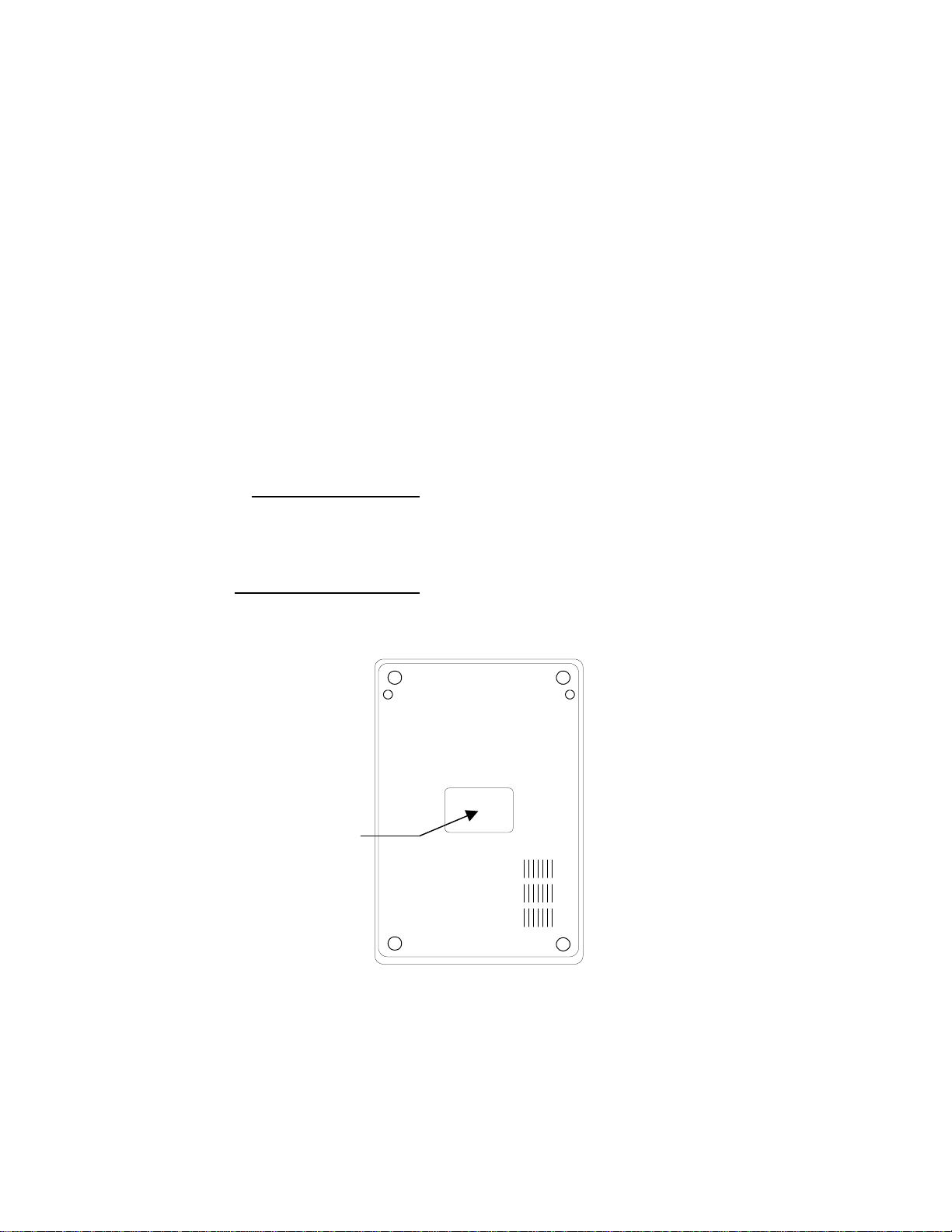
Note: The model number is printed on the compliance label attached to the bottom of the
printer. After un-packing please record the model number below for reference.
MODEL No:
SERIAL No:
Model No:
And
Figure 1 – Model and Serial Number Location
User's Guide 10

Model Features
For detailed feature specifications, please refer to Appendix A. Below is a brief summary of
printer features:
Standard Features
TM
PAL
#
Print and Program Language. The PAL
a powerful printer language combining both exceptional printing abilities with flexible
programming abilities. Because it is designed as both a printing and programming
language, it is extremely powerfu l, fle xib le, and eff ic ien t com pared to any other thermal
printer language on the market today.
TM
• PAL
Print ability: Free Type font engine with smooth scaling and rotation,
graphics with internal scaling, lines, boxes, all popular linear and 2D bar code types.
Full rotation and scaling of coordinate system. Ability to define and use print
procedures.
• PAL
TM
Programming ability: General I/O, file handling, loops, procedures, floating
point math, logical operators, database access, procedure definitions, string
manipulations, time/date functions.
#
Ability to store and run printer resident PALTM programs enabling powerful solutions for
a wide variety of print applications.
#
Powerful Windows Drivers are included that enable any Windows application to easily
access printer resident bar codes and fonts.
TM
Print and Programming Language is
FeatureMan(ager) program for quick and easy printer configuration
#
#
All popular linear and 2D bar codes
#
Serial and Parallel ports standard
#
Clamshell design for simplified media and ribbon loading
#
Reflective media detection sensor
#
Ribbon out sensor
#
Removable media spindle for 1 inch core sizes
#
Spring loaded release system for quick print head replacement
#
Rugged all metal print mechanism with high impact ABS housing
User's Guide 11
PALTM PRINT AND PROGRAM OVERVIEW
Printers featuring PALTM Print and Program ability can be used in several ways in any given
environment. This section describes 3 common ways this advanced capability is used. Details of
how to take advantage of this advanced ability can be found in the PAL
Reference Manual. For help and assistance determining the best way to use this ability in your
situation, please consult your sales representative.
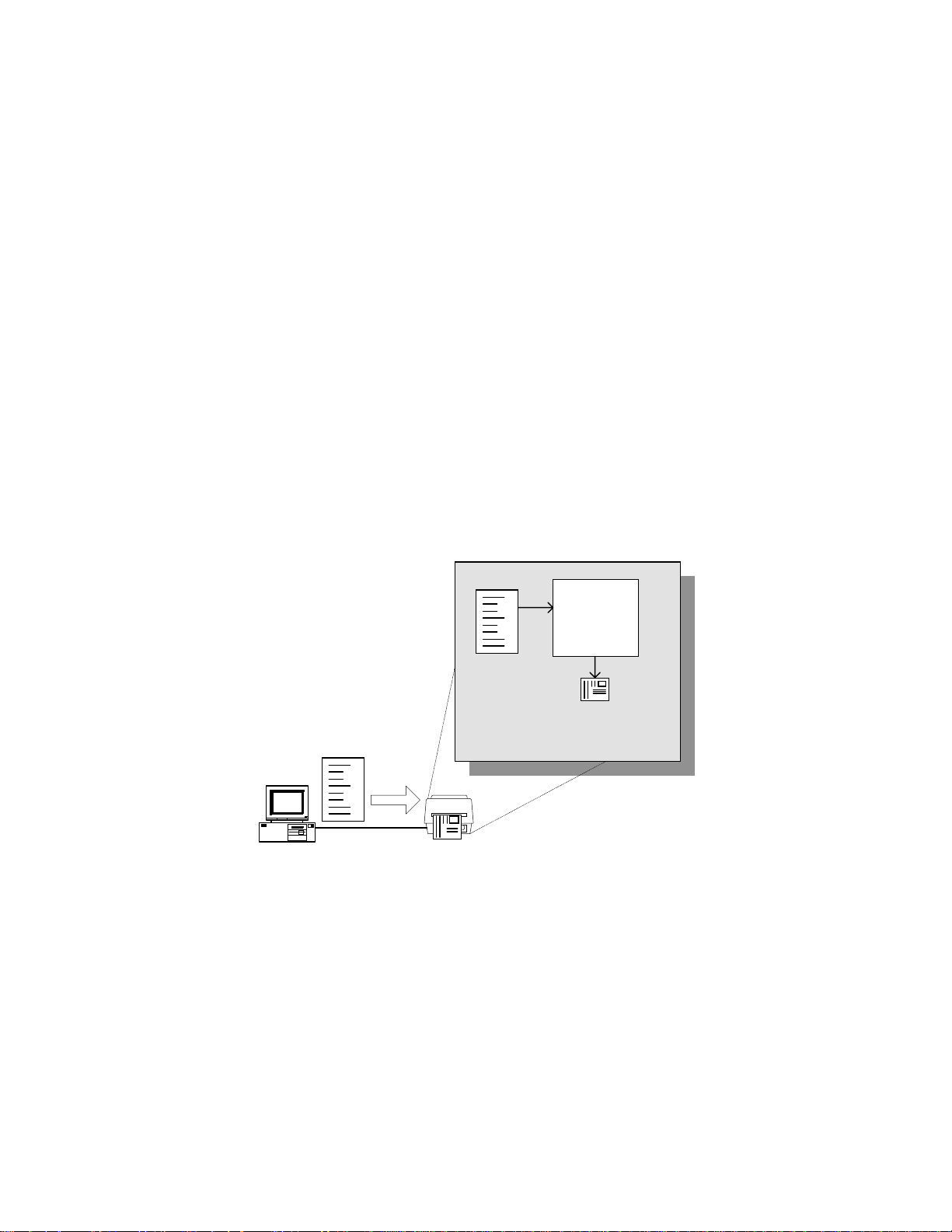
Traditional Printing
This environment represents the most common use of printers. Generally a single print job
TM
(PAL
interpreter accepts the print job, performs the required operator processing and prints the label,
tag, or ticket. Using a Windows driver in conjunction with a Windows application program is a
typical way to print in this environment. Alternatively, PAL
generated by any host application written to take advantage of this powerful language.
When a PAL
the printer. Print sequences generated by a Windows driver or host programs are simply sent to
the printer resulting in print output just like traditional printers.
print sequences) generates a single label. In this role the PALTM Print and Program
TM
print sequences may also be
TM
capable printer is used this way, no special “PALTM program” must be loaded on
PAL Sequence
TM
Print and Program
Host System
PAL Sequence
Interpreter
Document
PAL Printer
Figure 2 – Traditional Printing
PAL
Printed
User's Guide 12
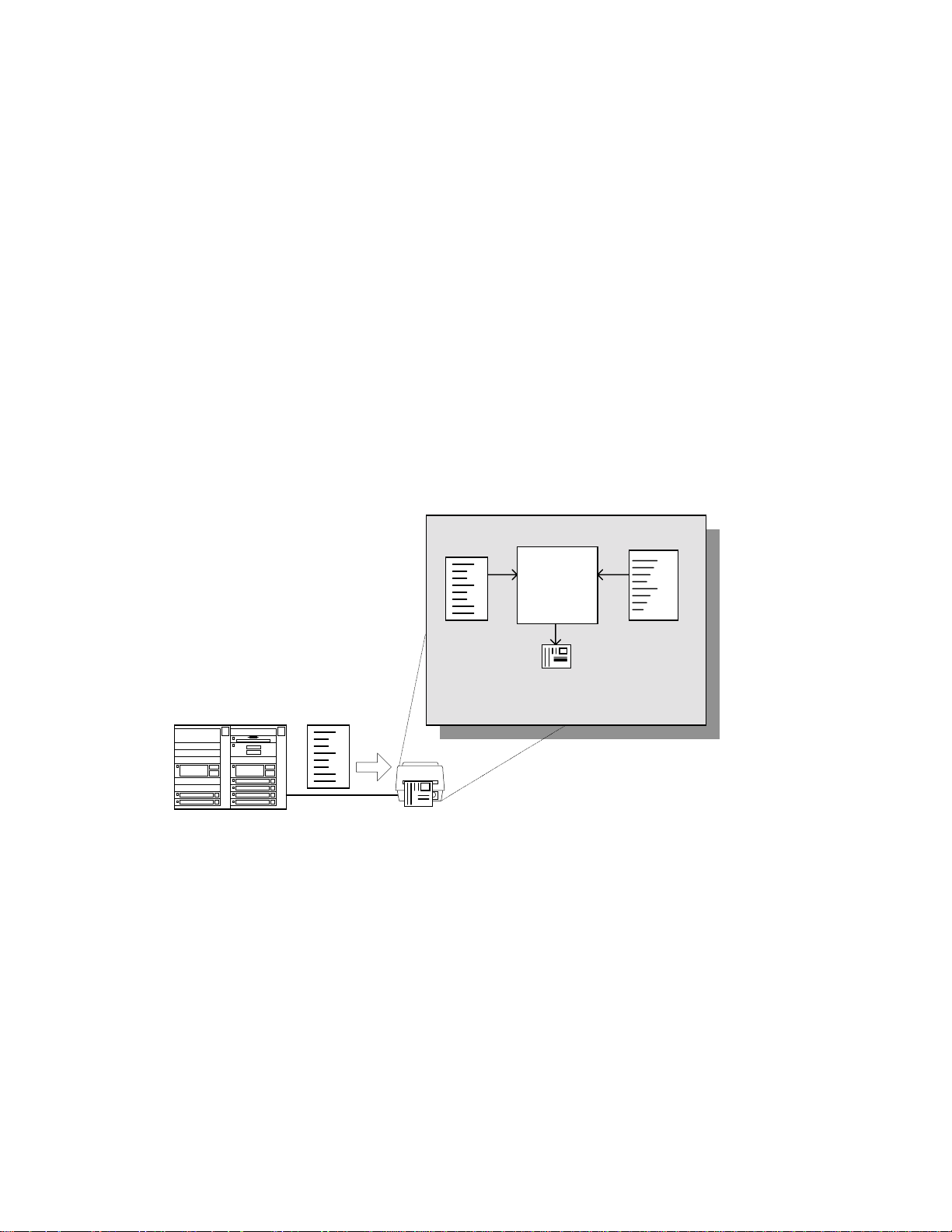
Legacy Data Stream Interpretation
PALTM Print and Program capable printers uniquely address applications where upgrading to
modern cost effective technology is desired. Often cost-prohibitive software reprogramming to
change a data stream prevents an organization from moving to new printing technologies.
TM
Using a PAL
Print and Program capable printer solves this problem. In this case a PAL
program is written which interprets a data stream normally sent to the legacy device being
replaced. This program is stored on the printer and is automatically executed each time the
printer is powered on. This program is able to produce a new label format based on this legacy
data. Even though the host computer is sending the exact same legacy data to the printer, the
label format can be completely different. For example the new format may include bar codes,
scaled and/or rotated fonts, lines, logo's etc. Even though the legacy device being replaced does
not support these print abilities, the new label format can.
For example, text only outputs such as produced by a dot-matrix printer or card embosser may
now be presented in a more functional format. Information in the data stream can be reformatted
into any size font in any rotation, or even printed as bar code. This example demonstrates how
TM
PAL
Print and Program capable printer can replace a legacy print device with no host software
changes required.
TM
Host System
PAL Data Stream
Legacy Data
Stream
PAL Printer
Legacy Data
Stream
PAL
Interpreter
Printed
Document
Figure 3 – Legacy Data stream Interpretation
Application
Printer
Flash Memory
User's Guide 13
UNPACKING AND INSPECTION
This section is provided to assist you in removing the printer from the shipping container and
setting it up in the application environment. Inspect the shipping carton and contact the carrier
directly to report any suspected damage.
1. With the shipping container in the upright position, remove the top foam packing piece.
2. Carefully, lift the printer straight up out of the box.
3. Remove the printer from the plastic bag and place the printer on a flat stable surface.
4. Remove the power supply from the separate enclosed box.
5. Remove the accessory kit and supplies.
6. Inspect the shipping container and the printer for any damage that may have occurred
during shipping.
Note:Save the box and all packing materials for future use, in the event the
printer needs to be shipped. Units returned for service in nonapproved packaging may void the warranty or increase repair costs
due to shipping damage.
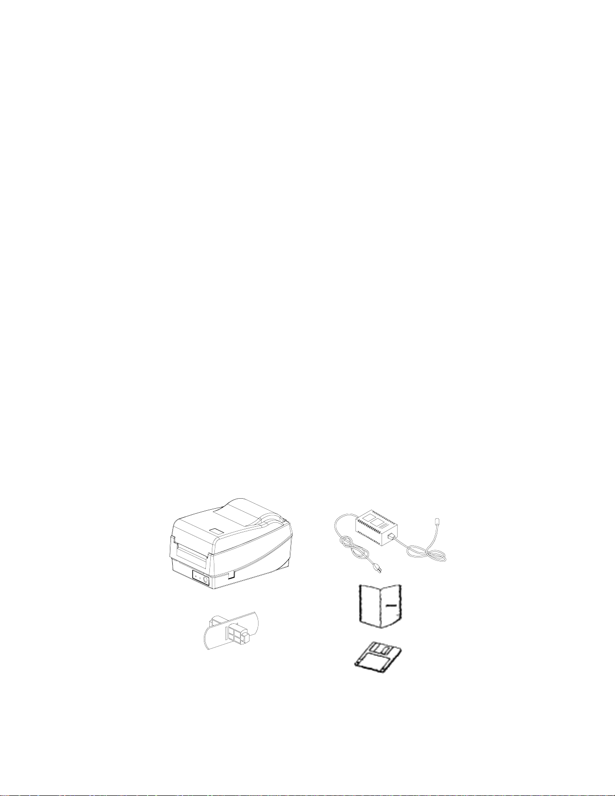
Verify that the printer box contains the following materials when unpacking:
a. Printer
b. Quick Start Up Guide
c. Media spindle (with retainer disk)
d. Power adapter (AC to AC)
e. CD or disks with User's manual and Windows drivers
f. A sample media roll (not pictured )
g. A sample ribbon roll and a take-up ribbon core (not pictured, Thermal Transfer printers
only)
Printer
Media Spindle
Power Adapter
Quick Start Up Guide
CD or Diskette
Figure 4 – Shipped with Printer
User's Guide 14
INSTALLATION AND CONFIGURATION
Finding a Location for the Printer
Determine a suitable location for the printer and power supply brick with the following
requirements:
• Find a flat stable surface with sufficient clearance to allow for interface cables and media
loading.
• The location should be near the host or terminal. Consider the distance between the host
and printer for the communication cable (serial or parallel cable).
• The location should be free from excessive direct sunlight, temperature, humidity, dust,
dirt, and debris.
• The location should be near a grounded AC power receptacle wired in compliance with
local ordinances.
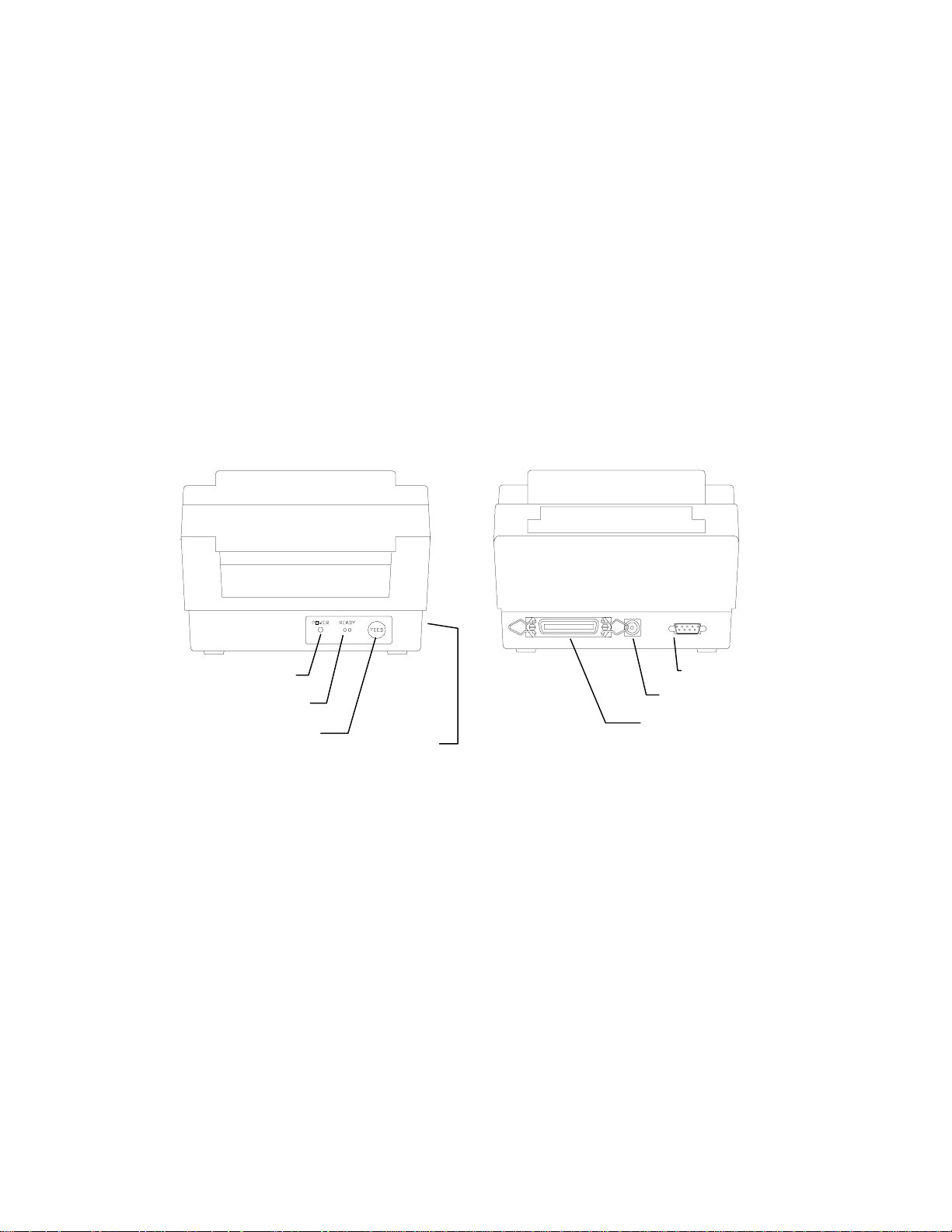
Power LED
Ready LED
Feed button
Serial Port
Power Jack
Parallel Port
On Switch
Figure 5 – Switches, Indicators and Connections
User's Guide 15
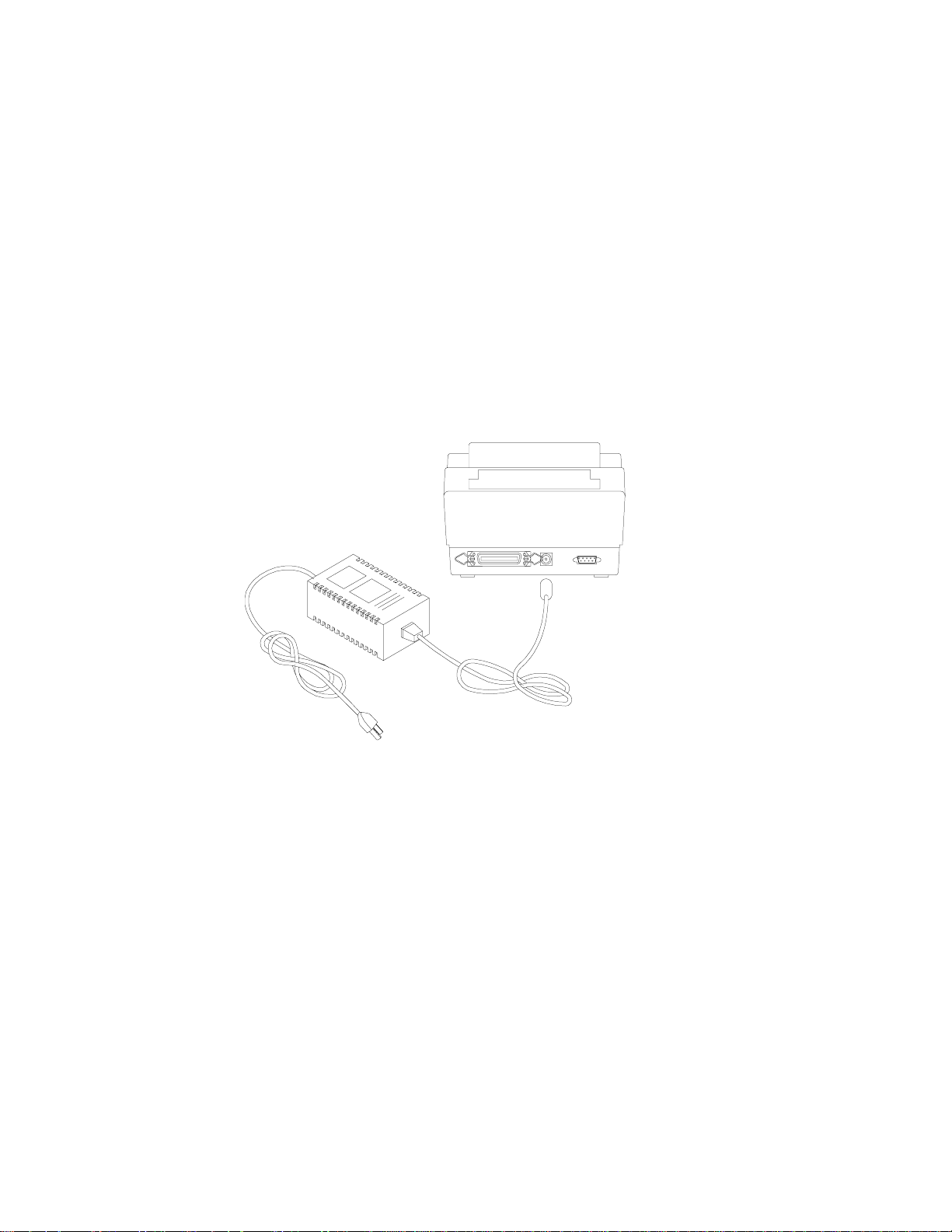
Connecting the Power Cord
1. Make sure that the source voltage matches the input voltage of the power adapter.
Caution: Incorrect source voltage could cause damage to the printer and/or the
power adapter.
2. Ensure the printer power switch is Off, “O”.
3. Connect the power plug to the Power Jack on the back of the printer. Avoid touching
the parallel connector.
4. Connect AC power plug to a suitable AC source.
5. Connect either a Centronics Parallel or RS-232 Cable.
Figure 6 – Power Connection
User's Guide 16
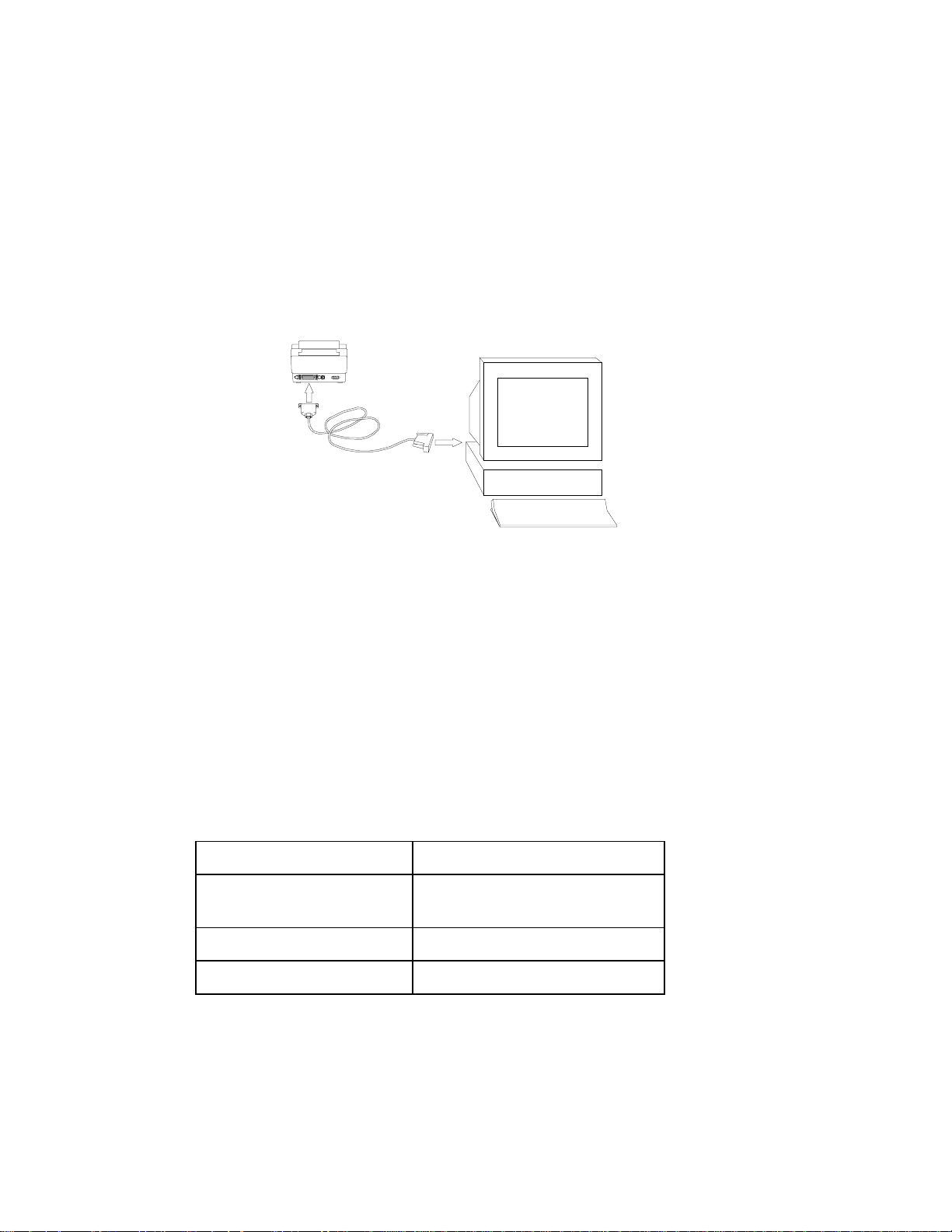
Connecting the Printer to Your Host
1. You can connect the printer with any standard Centronics cable to the parallel port of the
host computer or network print server.
2. Alternatively, you can connect the printer with a serial cable to the RS-232C port of your
computer or terminal. (For PC compatibles, the RS-232C port is COM1, COM2 or
COM3.)
Note:Using the Centronics interface allows for higher communication speed
than the serial interface.
Figure 7 – Communication Cable
3. If you use the serial port with your own cable, refer to the Appendix B and check the pin
connection.
Caution: Pin 9 on the serial port is directly connected to +5volts DC. Do not
connect this pin in your cable.
4. Be sure that the speed (baud rate) and protocol are the same between printer and host.
Note: Refer to the section Feature Management Mode for instructions on how to
change communication features.
Default serial port settings:
Speed (baud rate) 9600
Data format 1 start bit, 8 data bits and 1 stop
bit.
Parity None
Handshaking (Flow control) XON/XOFF and RTS/CTS
User's Guide 17
Loading the Ribbon
Thermal Transfer Media only
If Direct Thermal Media is used, skip to the section Loading Media.
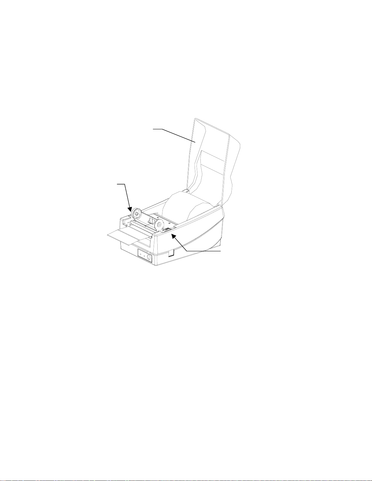
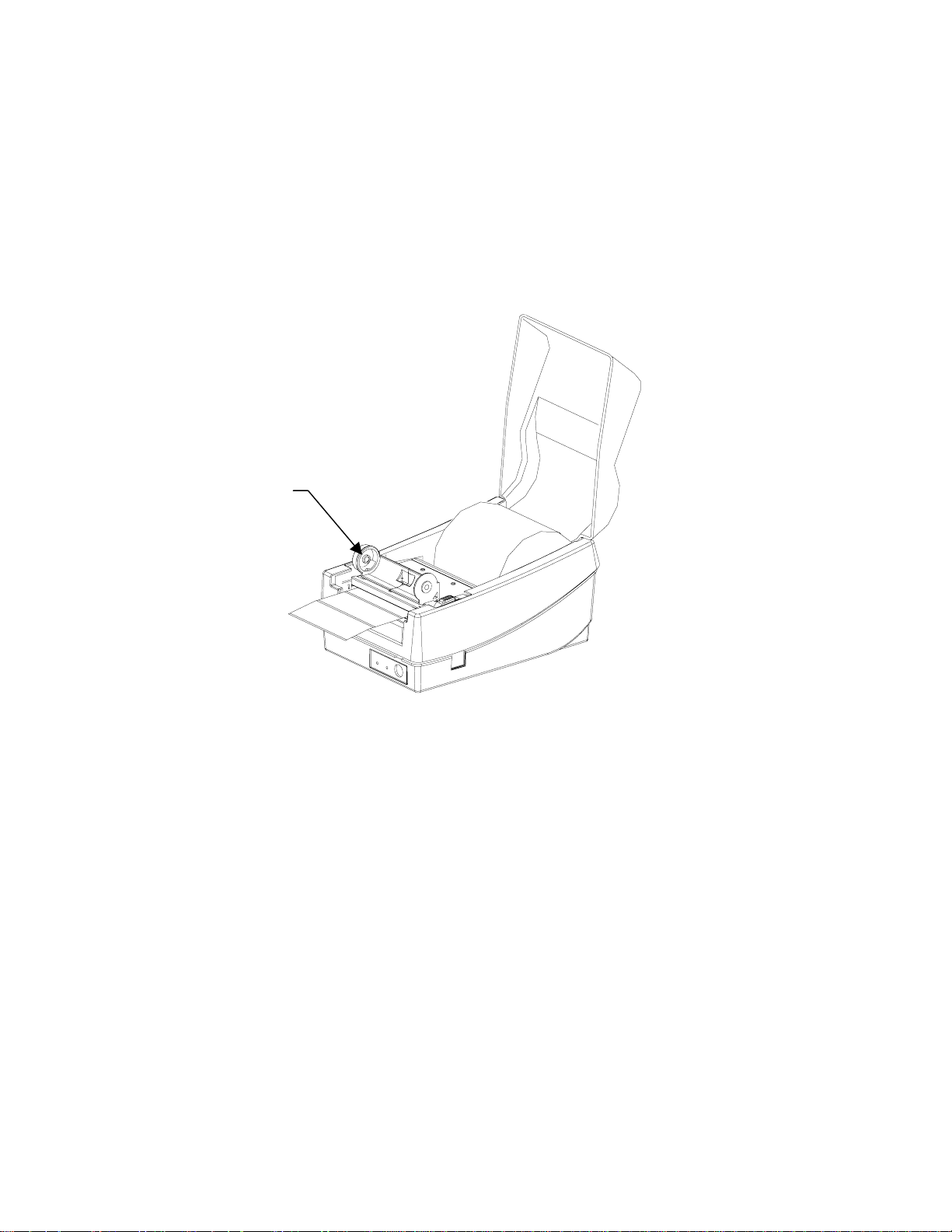
1. Open the Media Access Cover by lifting it up until it rests in the vertical position.
2. Slide the two Print Head Latches toward the back of the printer to unlock the print head
module.
Media Access Cover
Print Head Latch
Figure 8 – Print Head Latches
Print Head Latch
User's Guide 18
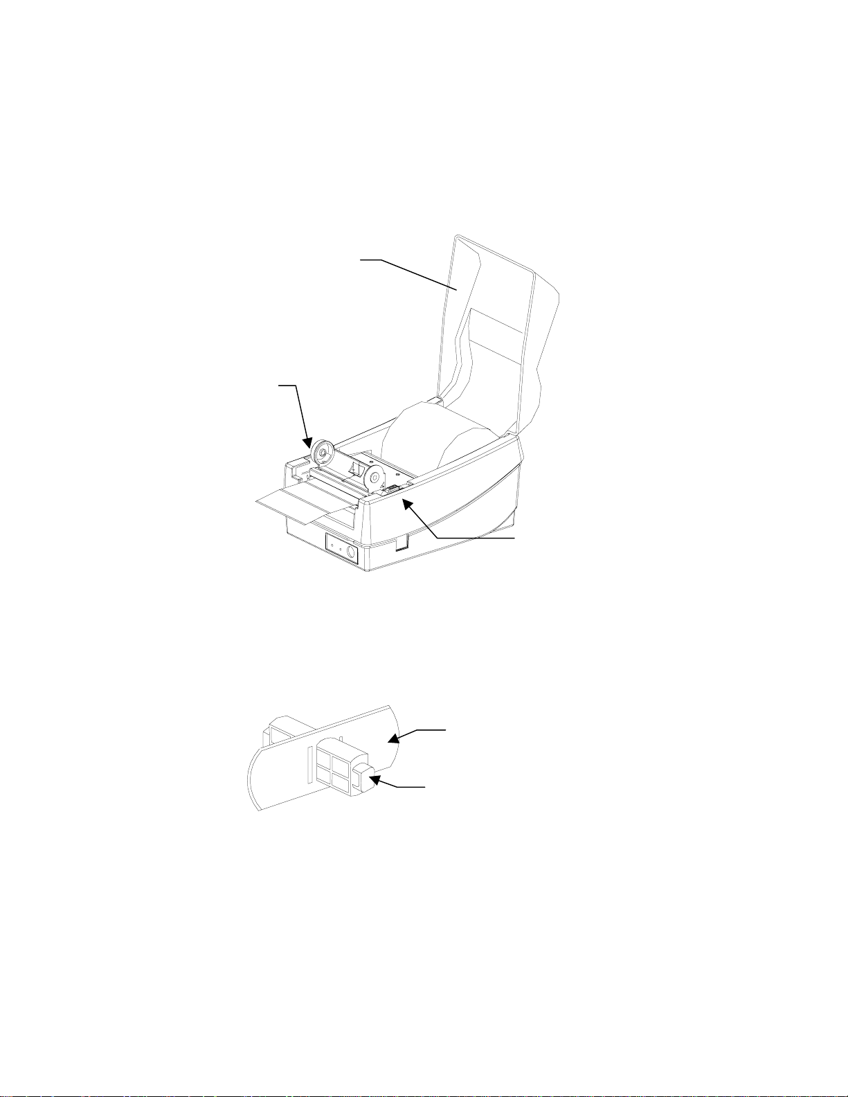
3. Raise the print head module to the vertical position.
4. Verify that the Ribbon Supply Core and the Take-up Core have two slots on the left
side of the core when the ribbon is positioned to go into the printer. These slots will be
mated to the notches on the Left Ribbon Holders.
Note:The notches are the drive mechanism for the ribbon. If the slots in the core are not
present or if they are in the wrong position, contact your ribbon supplier to obtain
a correct ribbon.
Notch
Figure 9 – Ribbon Holder Notch Location
User's Guide 19

5. Unwrap the Ribbon Supply Roll and place it into the Supply Holder of the print head
module. Insert the left end of the Ribbon Supply Roll (end with slots) into the Supply
Holder first then snap in the right end. Make sure that the ribbon core slots are mated
with the notches on the ribbon drive mechanism.
6. Place the Take-up Core into the Take-up Holder of the print head module. Insert the
left end of the Take-up Core into the Take-up Holder firs t then snap in the rig ht end.
Make sure that the Tak e-up core slots are mated with the notches on the ribbon drive
mechanism.
Take-up Holder
Ribbon
Supply Roll
Supply Holder
Figure 10 – Ribbon Loading
7. Manually rotate the Take-up Core until the transfer (typically black) portion of the
ribbon, from the Supply Holder start onto the Take-up Core.
8. Close and latch the print head module.
Note:The printer must be set to the Thermal Transfer mode to ensure the end of ribbon is
detected. Refer to the section Feature Management Mode for instructions on how
to change the Media Type feature.
User's Guide 20
Loading Media
1. Open the Media Access Cover by lifting it up until it rests in the vertical position.
2. Slide the two Print Head Latches toward the back and unlock the print head module.
3. Raise the print head module.
Media Access Cover
Print Head Latch
Print Head Latch
Figure 11 – Open Media Access Cover
4. Insert the Media Spindle into the core of the label media. The Retainer Disk should be
on the right of the media with the smooth side toward the media.
Retainer Disk
Media Spindle
Figure 12 – Media Spindle and Retainer Disk
5. Insert the Media Spindle and media assembly into the spindle holder slots inside the
printer. The labels should be face out feeding off the top of the roll.
6. Slide the media to the far left and then slide the Retainer Disk up against the media until
it is snug.
7. In the base of the printer locate the Right and Left Media Guides.
User's Guide 21
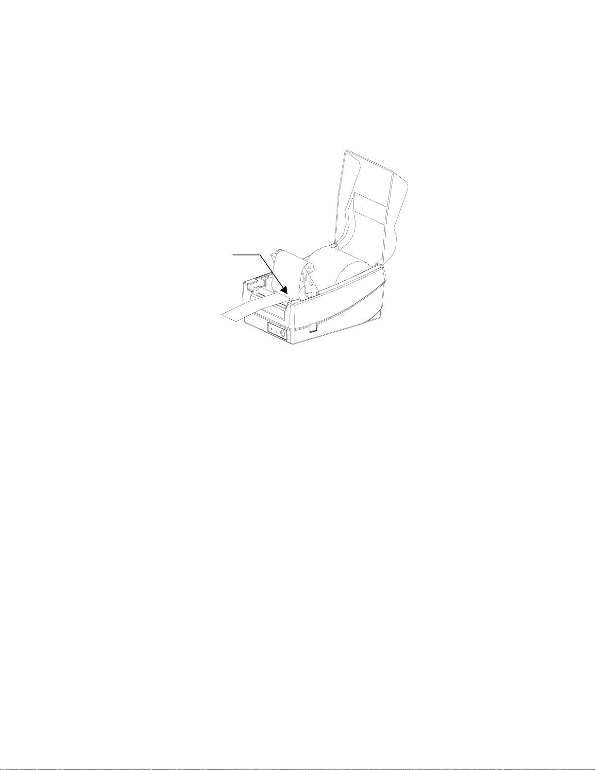
Note:The Right and Left Media Guides are ‘U’ shaped parts that are located at the
bottom of the paper path. Only the Right Media Guide can be moved. The media
should be snugly positioned in the ‘U’ portion of the guides.
8. Slide the adjustable Right Media Guide to the far right of the print er.
Media guides
Figure 13 – Loading Media
9. Pull out 6 inches of media and thread the end of the media under the Left Media Guide
and over the platen roller.
10. Slide the adjustable Right Media Guide to the left until it is gently touching the m edia.
Note:If the Media Guides are too loose the media may pull out from them and result in
false media out errors. If the Media Guides are too tight the media may buckle and
result in media jams.
11. Close and lock the print head module by pressing firmly until the right and left Print
Head Latches snap shut.
12. Close the Media Access Cover.
Note:The first time media is installed, the Media Sensor must be calibrated. After the
first calibration no further calibration is required unless the media type (length,
color, backing material, etc.) is changed or irregular feeding occurs. Refer to the
section Calibrating Media Sensors for instructions on how to calibrate the media
sensor.
User's Guide 22
Loading Media when Peel and Present Option is Installed
Follow the same procedures in "Loading Media" up until step 11, close and lock the
1.
print head module.
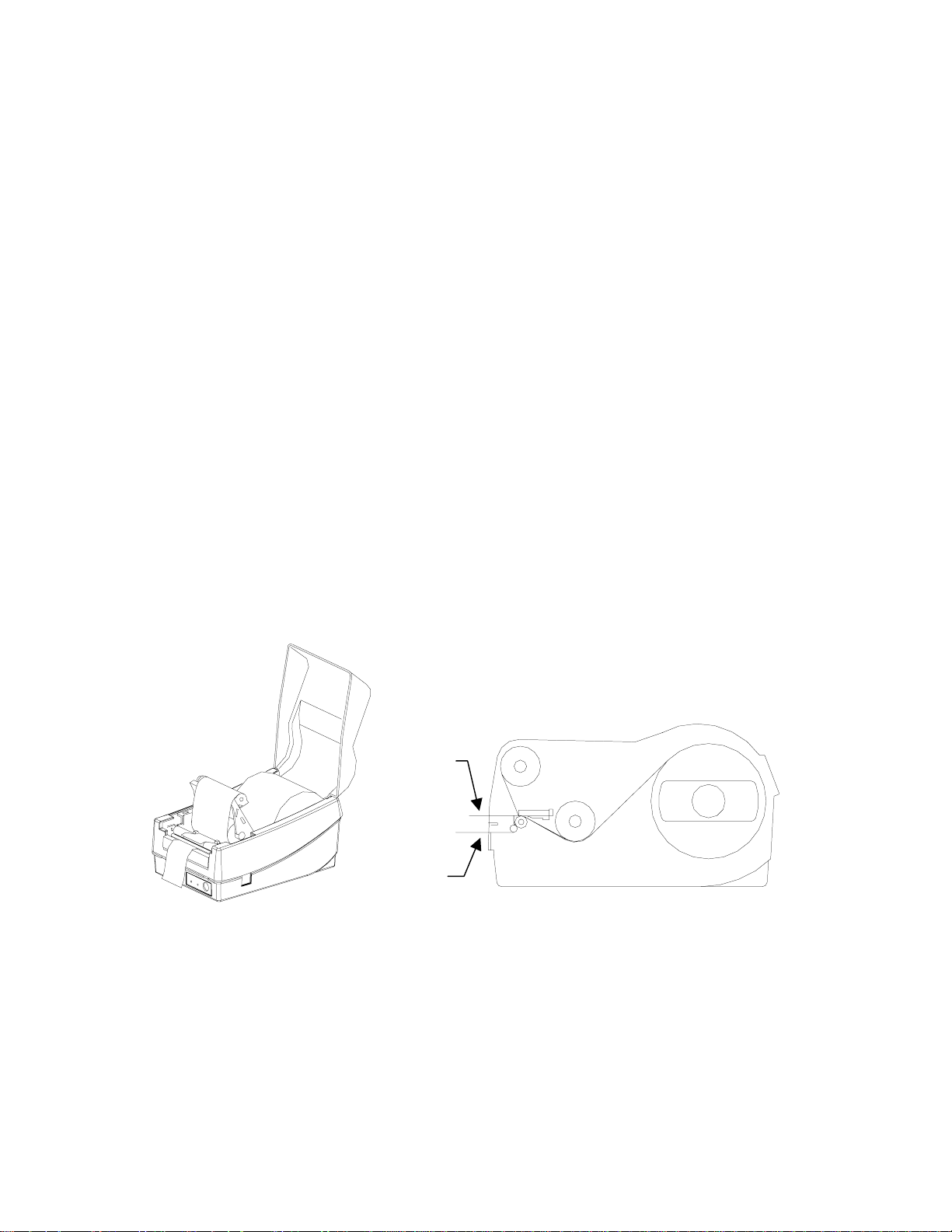
Peel off 6 inches of labels from its backing.
2.
Thread the label backing over the platen roller, over the Peel and Present Bar then back
3.
under the Peel and Present Bar towards the platen.
Turn on the power to “1” position.
4.
With the print head module still open, press the FEED key. The printer will advance the
5.
backing. Once the label backing comes out of the front of the printer, turn off the power
to “O” position.
Close and lock the print head module by pressing firmly until the right and left Print
6.
Head Latches snap shut.
Close the Media Access Cover.
7.
Turn on the power to “1” position.
8.
Press the FEED key to feed out the first label in the prin te r.
9.
Note:For the Peel and Present mode to function properly the Present Sensor must be
enabled. Refer to the section Feature Management Mode for instructions on how
to change the Present Sensor feature.
Label
Backing
Figure 14 – Loading Media - Peal and Present
User's Guide 23

Calibrating Media Sensors
Important: The first time media is installed, the Media Sensor must be calibrated. After
the first calibration no further calibration is required unless the media type
(length, color, backing material, etc.) is changed or irregular feeding occurs.
1. Ensure the printer is powered off.
2. Verify that the media is properly loaded and routed as detailed in Loading Media
section.
3. While pressing and holding the FEED key, power on the printer.
4. The READY LED (right most LED) will blink twice.
5. Continue to hold the FEED key until the printer begins to feed the media.
6. Release the FEED key.
7. When feeding stops the printer has completed the Media Sensor Calibration procedure.
The print head module can be opened and the media may be manually reversed back to
the first label to save label stoc k .
8. After closing the print head module, press the FEED key again to re-align the media to
the top of the label.
Note:For the Calibration procedure to function properly the proper Media Sensing Type
(Gap or Black Bar) must be selected. This setting may be made using the
FeatureMan program supplied.
User's Guide 24
 Loading...