

AMS Trex™ Device Communicator
User Guide
User Guide
Rev 8
September 2021

Copyright and trademark information
©
2021 Emerson. All rights reserved.
FOUNDATION™, HART® and WirelessHART® are marks of the FieldComm Group of Austin, Texas, USA.
The Emerson logo is a trademark and service mark of Emerson Electric Co.
All other marks are the property of their respective owners.
Notice
Important
Read this manual before working with the Trex unit. For personal and system safety, and for optimum product performance,
thoroughly understand the contents before using or servicing this product.
For equipment service needs, contact the nearest product representative.
Important
This device complies with Part 15 of the FCC Rules. Operation is subject to the following two conditions: (1) this device may not
cause harmful interference, and (2) this device must accept any interference received, including interference that may cause
undesired operation.
WARNING
If the Trex unit is used in a manner not specified by Emerson, the protection provided by the equipment may be impaired.
WARNING
Do not directly connect the ports or terminals on the Trex unit to any main line voltage.
WARNING
WARNING - POTENTIAL ELECTROSTATIC CHARGING HAZARD - SEE INSTRUCTIONS.
AVERTISSEMENT - DANGER POTENTIEL DE CHARGES ÉLECTROSTATIQUES - VOIR INSTRUCTIONS
2

User Guide Contents
September 2021
Contents
Chapter 1 AMS Trex Device Communicator User Guide...................................................................5
Chapter 2 AMS Trex Device Communicator overview..................................................................... 7
Chapter 3 Field Communicator application...................................................................................53
Chapter 4 Loop Diagnostics application......................................................................................125
Chapter 5 Fieldbus Diagnostics application................................................................................ 151
Appendix A Troubleshooting........................................................................................................ 179
Appendix B Technical specifications..............................................................................................183
Appendix C Product certifications................................................................................................. 189
Appendix D Wireless/Spectrum approvals.................................................................................... 191
Glossary .................................................................................................................................. 193
Index .................................................................................................................................. 197
User Guide iii

Contents User Guide
September 2021
iv User Guide

User Guide AMS Trex Device Communicator User Guide
September 2021
1 AMS Trex Device Communicator User
Guide
1.1 User Guide overview
The AMS Trex Device Communicator User Guide is written for instrument technicians who
work with field devices, including HART® and FOUNDATION™ fieldbus devices. The user
guide describes the hardware, connections to devices, the supported applications, and the
diagnostics you can run on devices, 4-20 mA current loops, or FOUNDATION fieldbus
segments.
Note
The Trex unit has two communication module options. This user guide describes both
modules. Any differences in the procedures based on these modules are noted.
1.2 Documentation conventions
The following conventions are used throughout:
Note
A note paragraph contains special comments or instructions.
CAUTION
A caution paragraph alerts you to actions that can have a major impact on the equipment
or stored data.
WARNING
A warning paragraph alerts you to actions that can have extremely serious consequences
for equipment and/or personnel.
1.3 Technical support
Contact your local representative or go to the AMS Trex Device Communicator website for
technical support contact information.
1.3.1
Information to provide to technical support
Before you call technical support personnel, have a detailed description of the issue,
including the information below (if applicable). Ensure you have the user manual for the
devices or digital control system available.
User Guide 5

AMS Trex Device Communicator User Guide User Guide
September 2021
Information about the Trex unit
• Operating system version on the Trex unit. (Tap Settings → About.)
• The serial number of the Trex unit. You can view the serial number from the Settings.
(Tap Settings → About → CPU Board Serial Number.) The serial number is located on
the label on the bottom of the Trex unit, near the power module LEDs.
• Version number for the application. (Tap Settings → Installed Applications.)
Troubleshooting device communication issues
• Does the control system support HART® or FOUNDATION™ fieldbus communications?
• What is the manufacturer and model of the control system?
• What is the device manufacturer name (or ID) and model revision of the device (exact
spelling if possible)?
• What task is being performed when the communication problem occurs?
• Can AMS Device Manager or another Trex unit communicate with the device?
• Are you having communication problems with multiple devices?
• Are there any error messages displayed when attempting to communicate with a
device?
• Does communication work when certain devices or processes are not running?
• What is the total cable length run from the termination panel to the device?
When you are working with HART devices, answer the following questions:
• What is the loop impedance (resistance value) in the HART loop?
• If a HART multiplexer is being used, what is the manufacturer and model?
• Is the device in burst mode?
• Is the device address set to "0"?
• Is more than one device on the loop?
• Is another master (primary or secondary) on the loop? (For example, a control system
or multiplexer.)
• Is the device powered by the Trex unit or an external power supply?
6 User Guide

User Guide AMS Trex Device Communicator overview
September 2021
2 AMS Trex Device Communicator
overview
The Trex unit supports HART® and FOUNDATION™ fieldbus devices, so you can configure
or troubleshoot in the field or on the work bench. Electronic Device Description Language
(EDDL) technology enables the Trex unit to communicate with a variety of devices
independent of device manufacturer.
Depending on the attached communication module, the Trex unit lets you:
• Configure HART and FOUNDATION fieldbus devices.
• Power one HART or FOUNDATION fieldbus device.
• Measure current and voltage.
• Perform diagnostics on a 4-20 mA current loop or FOUNDATION fieldbus segment.
The Trex unit includes a color LCD touchscreen, a Lithium-Ion power module (battery
pack), a processor, memory components, and optional communication modules.
CAUTION
When the Trex unit communicates with devices, follow all standards and procedures
applicable to the location. Failure to comply may result in equipment damage and/or
personal injury. Understand and comply with the sections in this manual.
2.1 Precautions for the Trex unit
Before operating the Trex unit, ensure:
• The Trex unit is not damaged.
• The power module is securely attached.
• All screws are sufficiently tightened.
• The communication terminal recess is free of dirt and debris.
• The communication module is securely attached.
CAUTION
Do not use a screen protector on an IS-approved Trex unit. Static discharge is possible.
2.1.1
Hazardous areas
A Trex unit that meets the Intrinsic Safety requirements (IS-approved) can be used in Zone
1, or Zone 2, for Group IIC, and Class I, Division 1 and Division 2, Groups A, B, C, and D
locations.
User Guide 7

AMS Trex Device Communicator overview User Guide
September 2021
An IS-approved Trex unit may be connected to loops or segments that are attached to
equipment located in Zone 0, Zone 1, Zone 2, for Group IIC; Zone 20, Zone 21, Zone 22,
and Class I, Division 1 and Division 2, Groups A, B, C, and D locations.
An IS-approved Trex unit can be ordered by selecting the KL option. The Trex unit has a
label that lists the approvals.
CAUTION
Do not use a screen protector on an IS-approved Trex unit. Static discharge is possible.
WARNING
Do not install, remove, or charge the Lithium Ion (Li-Ion) power module in a hazardous
area environment.
WARNING
Explosions can result in serious injury or death.
Use in an explosive environment must be in accordance with the appropriate local,
national, and international standards, codes, and practices. Please review the Technical
specifications and Product certifications sections of the AMS Trex Device Communicator
User Guide for any restrictions associated with safe use.
Electrical shock can result in serious injury or death.
8 User Guide

User Guide AMS Trex Device Communicator overview
September 2021
2.2 Front view of the Trex unit
Figure 2-1: Front view
2.2.1
A. Micro USB port (top)
B. Power button (side)
C. Strap connectors (side)
D. Touchscreen
E. Keypad
F. Charger port for the AC adapter (side)
Related information
LEDs on the power module
Touchscreen
Keypad
The Trex unit has a keypad that lets you navigate and select menus options. Use the four
arrow buttons to move across all selectable options on the screen, and use the checkmark
button to select an option.
The keypad also lets you enter text or numbers, based on the selected option or menu. An
onscreen keyboard is displayed. The four arrows let you navigate to a letter, number, or
symbol on the keyboard. Press the checkmark button or X button to select the option.
User Guide 9

AMS Trex Device Communicator overview User Guide
September 2021
Figure 2-2: Keypad
A. Cancel any unsaved changes or close a menu. Similar to a Back button.
B. Move through the menus and icons in the applications. Press the up, down, right, and
left arrow keys to highlight a menu option on a screen. The right and left arrow keys also
select items in a grid or on a graph, but they do not let you navigate to the next level in a
menu.
C. Open a menu item or accept any updates. Similar to an Enter button.
2.3 Touchscreen
The Trex unit has a resistive touchscreen that lets you select menu items and enter text.
Firmly press the screen to select an item. You need to apply more pressure than you would
for smart phones and tablets. If the touchscreen seems inaccurate, you can re-calibrate it.
All instructions in this manual are written for the touchscreen.
The touchscreen supports basic gestures, such as scroll up and scroll down. Multi-touch
gestures, such as pinch, are not supported.
10 User Guide
User Guide AMS Trex Device Communicator overview
September 2021
CAUTION
The touchscreen display on the Trex unit could be damaged if directly impacted. To avoid
damaging the touchscreen:
• Use the Trex carrying case with the faceplate closed to protect the touchscreen and
prevent any damage when transporting or carrying the Trex unit.
• Do not let the touchscreen come in contact with other objects.
• Contact the touchscreen with blunt items only. Sharp instruments, such as
screwdrivers, can damage the touchscreen.
Repairing the touchscreen requires replacement of the entire display assembly, which is
possible only at an authorized service center.
CAUTION
Do not use a screen protector on an IS-approved Trex unit. Static discharge is possible.
2.3.1
Supported gestures
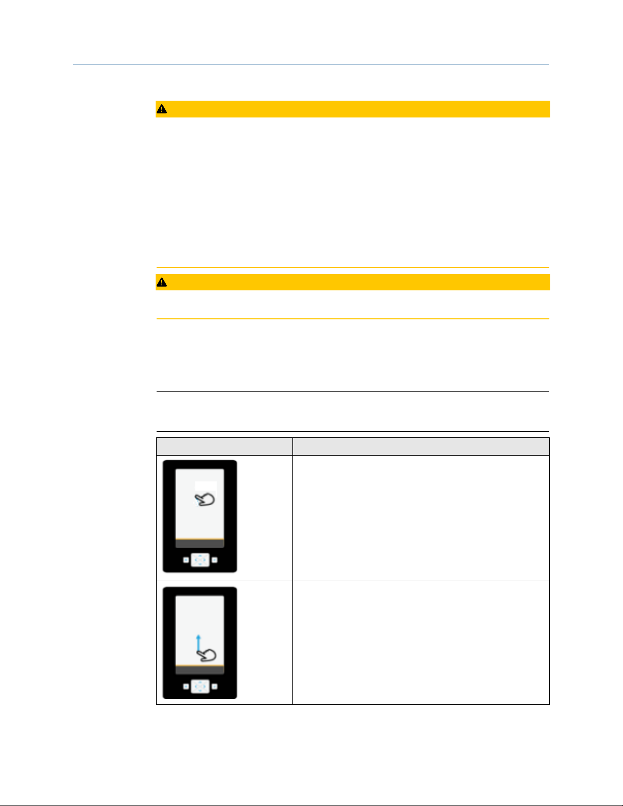
The Trex unit uses a single-tap to select an item on the screen. You do not need to doubletap an option on the screen.
Note
Multi-touch gestures, such as pinch, are not supported. Only single-touch gestures are
supported.
Gesture
Description
Tap.
Tapping a menu item opens another menu. For example, you
can tap a device description in the Field Communicator
application and a menu is displayed.
Press and hold.
Some menu items have a context menu associated with them.
Pressing and holding a menu item will activate the context
menu. For example, pressing and holding on a menu in the Field
Communicator application brings up a context menu that
allows access to help, or adding the item as a favorite.
Scroll down.
User Guide 11

AMS Trex Device Communicator overview User Guide
September 2021
Gesture Description
Scroll up.
Scroll right.
Used to move right on graph or grid, or to view additional
columns/data on a screen.
Scroll left.
Used to move left on graph or grid.
2.3.2 Enter text, numbers, or special characters
If an option requires you to enter text, the application displays a keyboard with the
permitted characters. You can enter letters, numbers, punctuation, and special
characters. Tap the screen or use the four arrows keys on the keypad to enter the desired
characters. Tapping the Shift Key twice on the keyboard enables Shift Lock.
For screens that require passwords, text is hidden by default but can be revealed before
confirming by tapping the reveal icon.
2.3.3
Clean the touchscreen
Clean the touchscreen with a soft cloth with pH-neutral detergent or alcohol. When the
touchscreen is contaminated by chemicals, immediately wipe them off with caution to
avoid injury to the human body.
12 User Guide

User Guide AMS Trex Device Communicator overview
September 2021
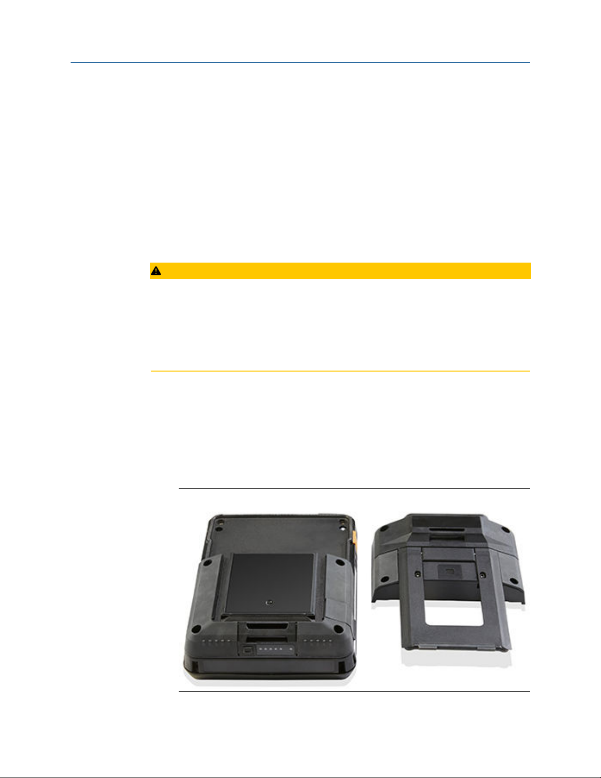
2.4 Back view of the Trex unit
You can access the communication module, the stand, and the power module.
Figure 2-3: Back view
A. Communication module
B. Stand
C. Power module
Related information
Communication modules
Replace the stand
Power module
2.4.1
User Guide 13
Serial numbers
The Trex unit has a serial number for each part, including the main unit, power module,
and communication module. The label on each part lists the serial number. You may need
to provide a serial number if you work with technical support.
You can view the serial number from the Settings. (Tap Settings → About → CPU Board
Serial Number.) The serial number is located on the label on the bottom of the Trex unit,
near the power module LEDs.

AMS Trex Device Communicator overview User Guide
September 2021
2.5 Communication modules
The Trex unit has two communication modules.
Device Communicator communication module
The Device Communicator communication module can connect to and communicate
with HART and FOUNDATION fieldbus devices on an externally-powered HART loop or
fieldbus segment. The Device Communicator communication module has unique
terminals for both HART and FOUNDATION fieldbus devices.
Figure 2-4: Device Communicator communication module
A. Connect to externally-powered FOUNDATION fieldbus devices.
B. Connect to externally-powered HART devices.
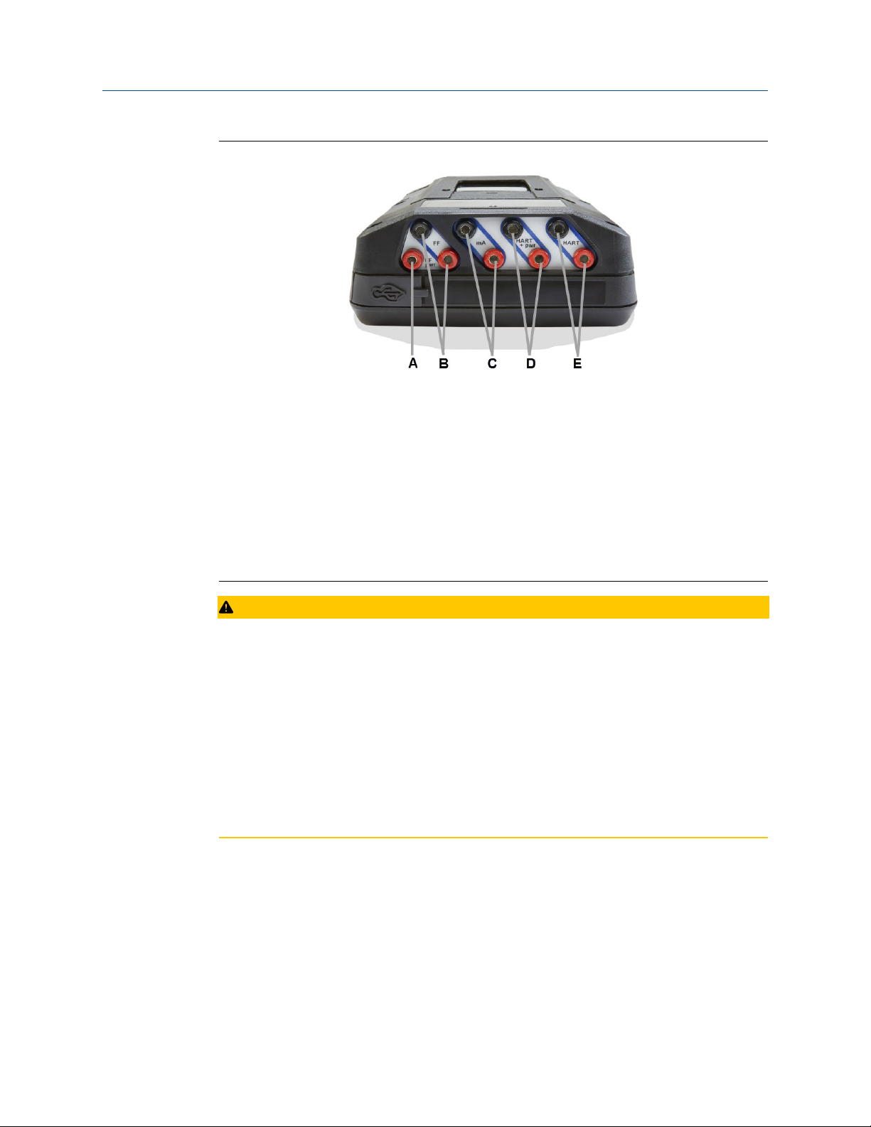
Device Communicator Plus communication module
The Device Communicator Plus communication module can connect to HART and
FOUNDATION fieldbus devices, measure current and voltage, and power a device.
14 User Guide
User Guide AMS Trex Device Communicator overview
September 2021
Figure 2-5: Device Communicator Plus communication module
A. Power a FOUNDATION fieldbus device. You need to connect the FOUNDATION fieldbus
Power Plug to the FF pwr and the positive FF terminals.
B. Connect to a FOUNDATION fieldbus device that is externally-powered or powered by the
Trex unit.
C. Measure current on a 4-20 mA current loop.
D. Power and connect to a HART device. The HART+pwr terminals can measure the current
output of a connected transmitter or control the current input to a connected positioner.
The terminals also have a loop resistor for device communication.
E. Connect to an externally-powered HART device. The HART terminals also have an
optional loop resistor for enabling HART communications on 4-20 current loop and
optional current control for moving a positioner.
CAUTION
• Before you insert or remove a communication module, ensure the Trex unit is powered
off.
• Ensure sufficient grounding. Ensure the personnel, working surfaces, and packaging
are sufficiently grounded when handling electrostatically sensitive parts.
• Avoid touching the pins on the connectors or components. Discharged energy can
affect the modules.
• When you insert/attach the communication module to the Trex unit, do not over
tighten the screws. Use 0.5Nm maximum torque load.
• Remove the USB cable from the Trex unit before connecting to a device.
User Guide 15

AMS Trex Device Communicator overview User Guide
September 2021
WARNING
• The Trex unit cannot power a 4-wire device. Do not connect Trex unit to the power
terminals of a 4-wire device. This can blow a fuse inside the Trex unit. The repair/
replacement will need to be completed at an authorized service center.
• Do not connect lead sets to the HART and HART + pwr terminals at the same time. If
the lead sets are connected to devices, this increases the chance of wiring mistakes and
could create a short in the HART loop.
• Do not add any external power to the device when the Trex unit is powering the device.
This can blow a fuse inside the Trex unit. The repair/replacement will need to be
completed at an authorized service center. Ensure the device is disconnected from the
loop/segment and no other wires are connected to the device before providing power
from the Trex unit.
• Do not use the Trex unit to power a WirelessHART device. Providing power to a
WirelessHART device may damage the device.
• Do not connect the mA terminals (ammeter) in parallel with a powered 4-20 mA
current loop. Ammeters have low resistance. This can disrupt the loop and cause
devices to report incorrect values or positioners to move unexpectedly.
2.5.1
• Do not connect the mA terminals on the Trex unit to a power supply that is not current
limited to 250 mA. This can blow a fuse inside the Trex unit. The repair/replacement
will need to be completed at an authorized service center.
Ammeter on the Device Communicator Plus communication module
The Device Communicator Plus communication module has several ammeters for reading
current:
1. Ammeter in the mA terminals. This ammeter is intended for quick measurements
and is for reference only.
2. Ammeter in the HART + pwr terminals. This ammeter is used when the Trex unit is
powering a transmitter. This ammeter is intended for tasks including digital-toanalog trims where a higher accuracy ammeter is required.
3. Ammeter in the HART + pwr and HART terminals. This ammeter is used when the
Trex unit is controlling current or is powering a positioner. The ammeter is intended
to give feedback on the output current from the Trex unit and is for reference only.
16 User Guide
User Guide AMS Trex Device Communicator overview
September 2021
WARNING
• Do not use the HART + pwr and mA terminals in series when the Trex unit powers a
device.
• Do not connect the mA terminals (ammeter) in parallel with a powered 4-20 mA
current loop. Ammeters have low resistance. This can disrupt the loop and cause
devices to report incorrect values or positioners to move unexpectedly.
• Do not connect the mA terminals on the Trex unit to a power supply that is not current
limited to 250 mA. This can blow a fuse inside the Trex unit. The repair/replacement
will need to be completed at an authorized service center.
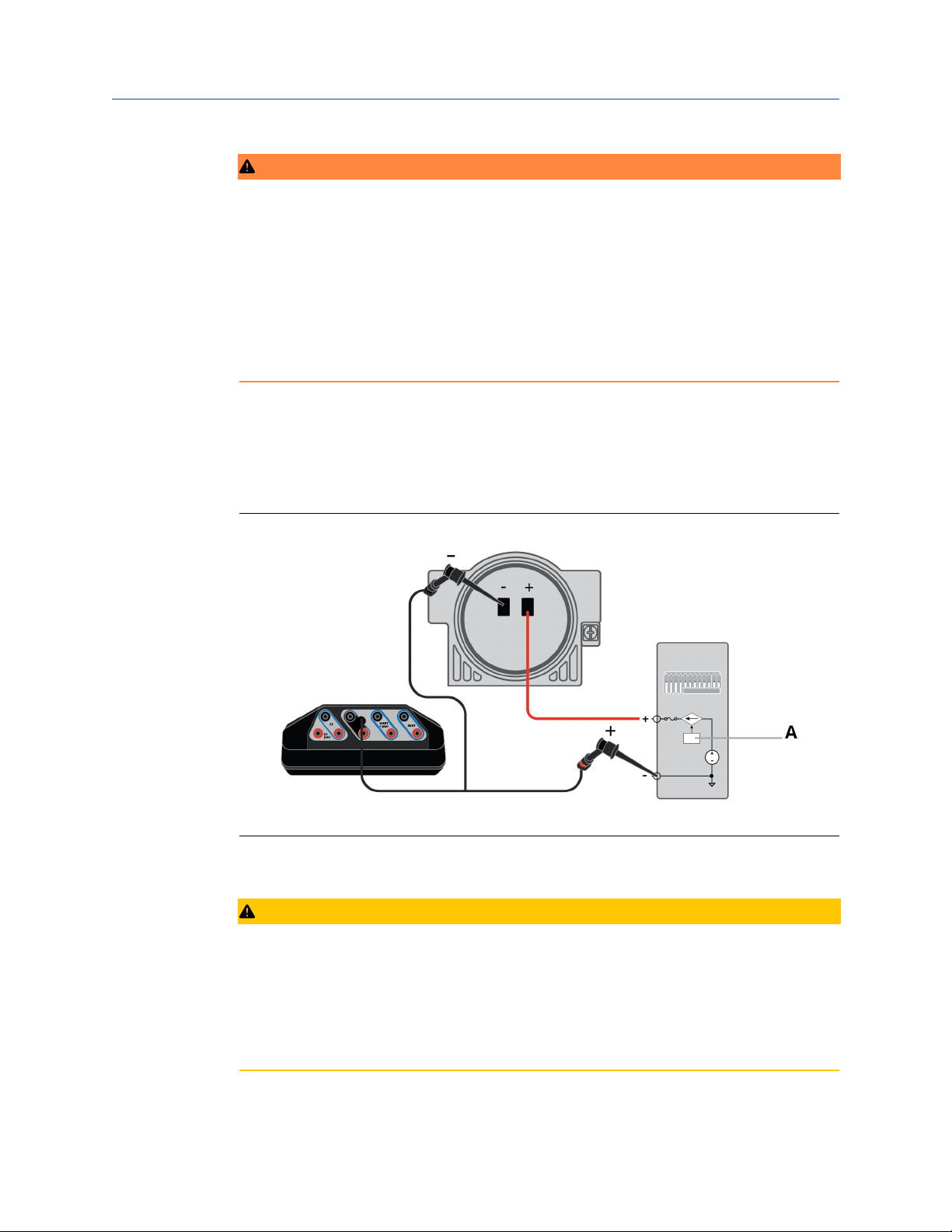
For best results when using the mA terminals, do the following:
• Avoid using the ammeter in cold or very hot temperatures. Extreme temperatures can
affect the accuracy of the measurements.
• Connect the mA terminals on the Trex unit to the "low-side" of the device. See the
example below.
2.5.2
Figure 2-6: "Low-side" ammeter connection
A. Analog output
Install a communication module
CAUTION
• Ensure sufficient grounding. Ensure the personnel, working surfaces, and packaging
are sufficiently grounded when handling electrostatically sensitive parts.
• Avoid touching the pins on the connectors or components. Discharged energy can
affect the modules.
• Handle the module with care. It is possible to bend the pins on the module's connector.
User Guide 17
AMS Trex Device Communicator overview User Guide
September 2021
Procedure
1. Turn off the Trex unit.
2. Place the Trex unit face down on a level, secure surface.
3. Place the communication module into the top of the Trex unit, and carefully align
the communication module with the connector on the Trex unit.
4. Gently press the communication module until it is seated properly with the Trex
unit.
5. Tighten the four screws using a screwdriver. Do not over tighten the screws. Use
0.5Nm maximum torque load.
2.5.3 Remove a communication module
CAUTION
• Ensure sufficient grounding. Ensure the personnel, working surfaces, and packaging
are sufficiently grounded when handling electrostatically sensitive parts.
• Avoid touching the pins on the connectors or components. Discharged energy can
affect the modules.
• Handle the module with care. It is possible to bend the pins on the module's connector.
Procedure
1. Turn off the Trex unit.
2. Place the Trex unit face down on a level, secure surface.
3. Remove any connected lead sets.
4. Loosen the four screws on the module using a screwdriver.
5. Gently lift the communication module straight away from the Trex unit. Do not
slide the communication module.
Figure 2-7: Trex unit with the communication module removed
18 User Guide

User Guide AMS Trex Device Communicator overview
September 2021
2.6 Power module
A rechargeable Lithium-Ion power module powers the Trex unit. A typical charge should
last for more than 8 hours of continuous use. The Trex unit displays a low-battery warning
when the remaining charge reaches a set level. Ensure you save any unsent data for a
device before the power module reaches a low level.
You do not need to discharge or calibrate the power module. Contact technical support if
you experience any problems with the power module.
WARNING
Do not install, remove, or charge the Lithium Ion (Li-Ion) power module in a hazardous
area environment.
2.6.1
Precautions for the power module and AC adapter
Understand and follow the precautions below before using the power module or AC
adapter.
• When transporting a Lithium-Ion power module, follow all applicable regulations.
• Ensure sufficient grounding. Ensure the personnel, working surfaces, and packaging
are sufficiently grounded when handling electrostatically sensitive parts.
• Avoid touching the pins on the connectors or components. Discharged energy can
affect the power modules.
• Protect the power module and AC adapter from moisture, and respect operating and
storage temperature limits listed in the AMS Trex Device Communicator User Guide. The
AC adapter is for indoor use only.
• Do not cover the power module or AC adapter while charging. Do not subject them to
prolonged periods of direct sunlight, or place them on or next to heat-sensitive
materials.
• Charge the power module with only the provided AC adapter. The AC adapter should
not be used with other products. Failure to comply may permanently damage the Trex
unit and void the IS approval and warranty.
• Do not open or modify the power module or AC adapter. There are no user-serviceable
components or safety elements inside. Opening or modifying them will void the
warranty and could cause personal harm.
• Clean the AC adapter by clearing the terminal of dirt and debris, if required.
• If the AC adapter is used in a manner not specified by Emerson, the protection provided
by the equipment may be impaired.
• The AC adapter comes complete with interchangeable plug heads for UK, USA, EU and
AU.
• The maximum operating altitude for the AC adapter is 2000 meters.
User Guide 19

AMS Trex Device Communicator overview User Guide
September 2021
2.6.2 AC adapter
The Trex unit includes an AC adapter for recharging the power module. The Trex unit is
fully operational while the AC adapter charges the power module.
WARNING
Do not install, remove, or charge the Lithium Ion (Li-Ion) power module in a hazardous
area environment.
Figure 2-8: AC adapter
Related information
Precautions for the power module and AC adapter
2.6.3
20 User Guide
LEDs on the power module
The power module has six LEDs to indicate the charging status. Press the button next to
the LEDs to illuminate the LEDs and view the current charge level.

User Guide AMS Trex Device Communicator overview
September 2021
Figure 2-9: LEDs showing approximately 100 percent charge
2.6.4
A. AC adapter LED. Lights up when the AC adapter is attached to the power module. A
green light indicates the power module is fully charged. An orange light indicates the
power module is charging. No LED indicates the power module is not being charged.
B. Power module LEDs. Each solid green LED indicates approximately 20 percent charge. A
blinking LED indicates the power module is charging within that 20 percent range.
C. Power module button. Press to illuminate the power module LEDs.
View the remaining power module charge
You can check the remaining power module charge from several places.
Procedure
1. Check the charge from the power module.
a) Press the power module button to illuminate the 5 LEDs.
b) View the LEDs. Each solid green LED indicates approximately 20 percent
charge.
2. Check the charge from the Trex Home screen.
a) Tap Settings or the status bar at the top of the screen.
b) Tap More → Power Management.
The charge level is displayed.
User Guide 21

AMS Trex Device Communicator overview User Guide
September 2021
Related information
LEDs on the power module
Status bar
2.6.5 Charge the power module
Fully charge the power module before using it in the field. The Trex unit is fully operable
when the power module is charging. An overcharge condition will not occur if the AC
adapter is connected after charging completes. You can charge the power module when it
is attached to or detached from the Trex unit.
To maintain performance, charge the power module frequently, preferably after each use.
Limit full discharges, if possible.
If you experience communication issues when working with a device, remove the AC
adapter from the Trex unit.
WARNING
Do not install, remove, or charge the Lithium Ion (Li-Ion) power module in a hazardous
area environment.
2.6.6
Procedure
1. Plug the AC adapter into a power outlet.
2. Attach the AC adapter cable to the charger port on the lower left side of the Trex
unit.
A full charge takes approximately three to four hours.
Install the power module into the Trex unit
CAUTION
• Ensure sufficient grounding. Ensure the personnel, working surfaces, and packaging
are sufficiently grounded when handling electrostatically sensitive parts.
• Avoid touching the pins on the connectors or components. Discharged energy can
affect the modules.
WARNING
Do not install, remove, or charge the Lithium Ion (Li-Ion) power module in a hazardous
area environment.
Procedure
1. Place the Trex unit face down on a level, secure surface.
2. Align the power module with both sides of the Trex unit, and carefully place the
power module onto the Trex unit.
22 User Guide

User Guide AMS Trex Device Communicator overview
September 2021
3. Insert and tighten the four screws with a Torx® screwdriver to secure the power
module. Do not over tighten the screws. Use 0.5Nm maximum torque load.
2.6.7 Remove the power module from the Trex unit
CAUTION
• Ensure sufficient grounding. Ensure the personnel, working surfaces, and packaging
are sufficiently grounded when handling electrostatically sensitive parts.
• Avoid touching the pins on the connectors or components. Discharged energy can
affect the modules.
WARNING
Do not install, remove, or charge the Lithium Ion (Li-Ion) power module in a hazardous
area environment.
Procedure
2.6.8
1. Turn off the Trex unit.
2. Place the Trex unit face down on a level, secure surface.
3. Use a Torx® screwdriver to loosen the four screws on the power module. The screws
do not need to be fully removed.
4. Gently lift the power module straight away from the Trex unit. Do not slide the
power module.
Figure 2-10: Trex unit with the power module removed
Maintain the power module
To help maintain the performance and life of the power module, understand and follow
the guidelines below:
• Recharge the power module frequently, preferably after each use or at night. Limit the
number of full discharges, if possible.
User Guide 23

AMS Trex Device Communicator overview User Guide
September 2021
• Avoid frequent use at high temperatures because this can reduce performance.
• Use a dry location at or near room temperature when storing the power module for an
extended time. Prolonged storage at higher temperatures can reduce performance.
• Ensure the remaining charge level is at or near mid-capacity when storing for an
extended time. The remaining charge will slowly drain during storage. Periodically
charge the power module to ensure the remaining charge does not drain to low levels.
2.7 Accessories
The Trex unit includes the following accessories:
• Lead set.
• A FOUNDATION fieldbus Power Plug to enable the Trex unit to power a FOUNDATION
fieldbus device.
• A USB cable to connect the Trex unit to PC applications.
• AC adapter.
2.7.1
• A handstrap that can be connected to either side of the Trex unit.
Cables and lead sets
The Trex unit comes with a lead set so it can connect to a device. The lead set attaches to
one set of terminals on the top of the Trex unit. The positive lead is marked with a red
band near the banana jacks.
Note
When you remove the lead set from the Trex unit, do not pull on the cable. Grab the plug/
connectors and remove the lead set from the terminals.
The Trex unit may also include the FOUNDATION fieldbus Power Plug, which is used to
power one FOUNDATION fieldbus device. Use the FOUNDATION fieldbus Power Plug with
the Device Communicator Plus communication module. The plug attaches to the FF pwr
terminal and the positive FF terminal on top of the lead set.
Figure 2-11: FOUNDATION fieldbus Power Plug
24 User Guide

User Guide AMS Trex Device Communicator overview
September 2021
Figure 2-12: FOUNDATION fieldbus Power Plug attached to the Trex unit
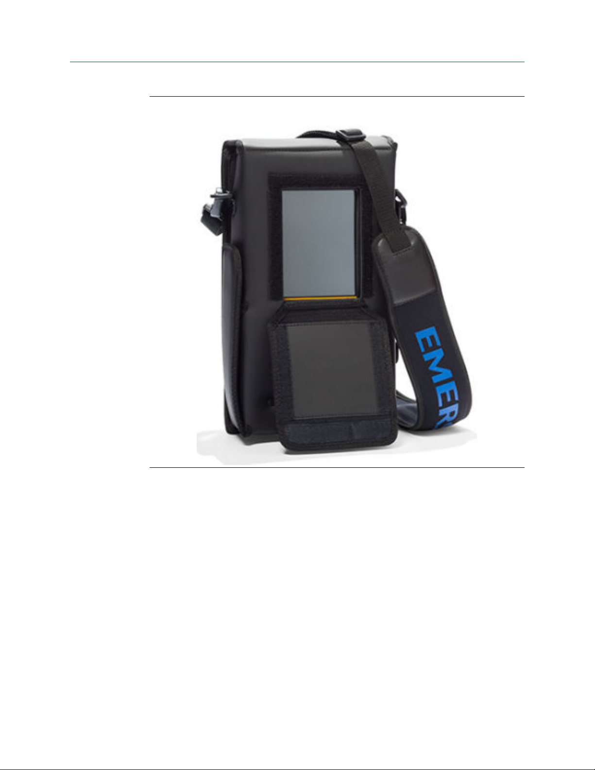
2.7.2 Carrying case for the Trex unit
A carrying case is available for the Trex unit to hold it and store lead sets, the AC adapter,
and other accessories. The case has several compartments and a shoulder strap.
When transporting or carrying the Trex unit in the case, ensure the face plate on the case is
closed. This protects the touchscreen from unexpected contact with other objects.
Note
Ensure the carrying case is clean. Otherwise, this can affect the strength of the connection
on the strap or faceplate. When carrying the Trex unit in high places, use the hand strap.
The bottom compartment on the carrying case opens so you can store the AC adapter
with the Trex unit.
User Guide 25
AMS Trex Device Communicator overview User Guide
September 2021
Figure 2-13: The carrying case
2.8 Power on or off
Procedure
1. To power on, press and hold the power button on the upper left side of the Trex unit
for one second.
2. To power off, do one of the following:
• Quickly press the power button, and then tap Turn Off.
• Tap Settings or the status bar at the top of the screen, and tap More → Power
Management → Turn off.
2.8.1
26 User Guide
Reboot
Procedure
1. Tap Settings or the status bar at the top of the screen.
User Guide AMS Trex Device Communicator overview
September 2021
2. Tap More → Power Management → Reboot.
2.8.2 Hard shut down
If the Trex unit is unresponsive, do a hard shut down and then restart the Trex unit. Do not
use this as your normal shut down method. Contact technical support if you need to
repeatedly use the hard shut down.
Procedure
Press and hold the power button for 12 seconds.
The Trex unit shuts down.
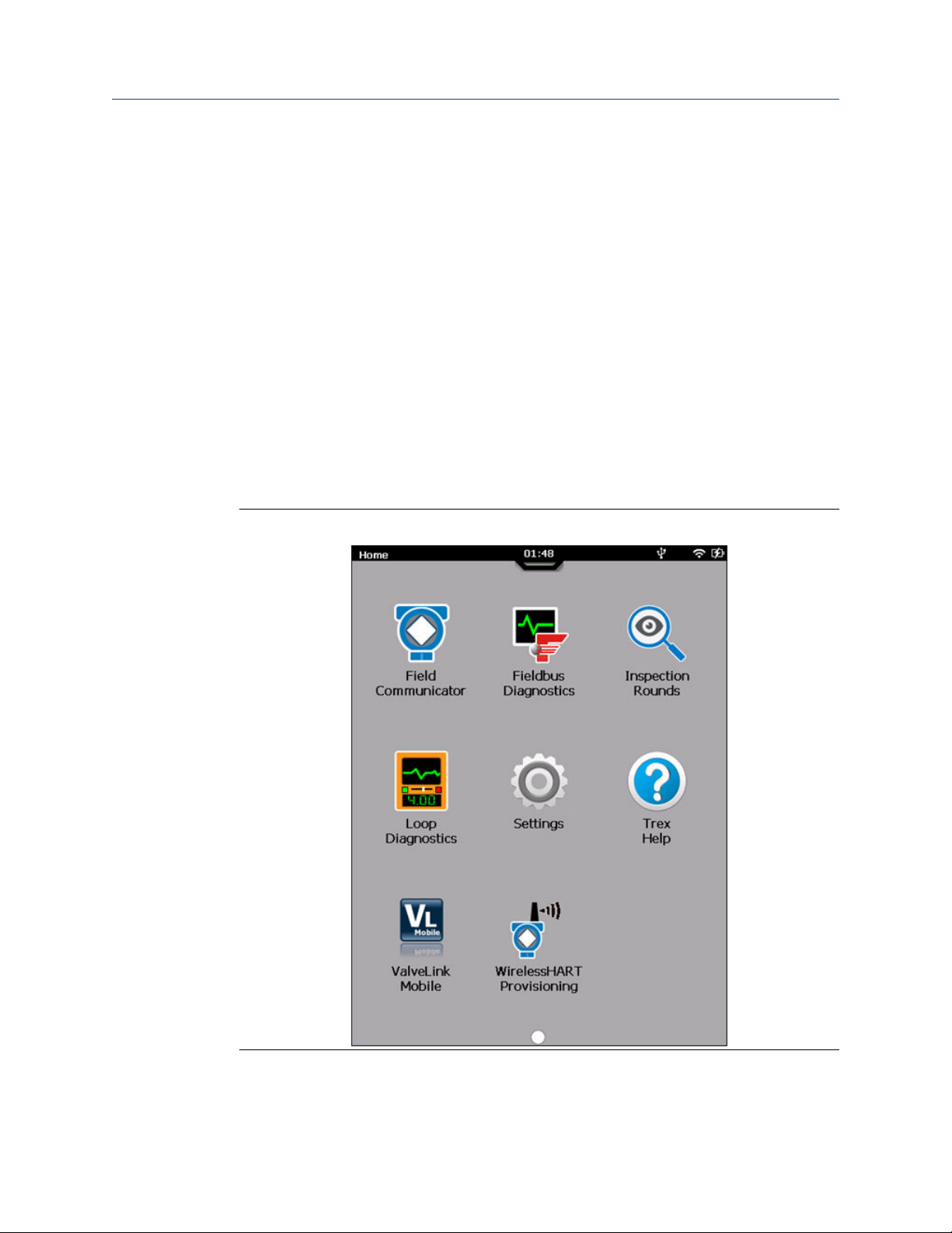
2.9 Home screen
The Home screen appears after you power on the Trex unit. The Home screen displays the
installed applications and the status bar at the top of the screen. The Home screen may
display one or more of the applications listed below.
Figure 2-14: Home screen
User Guide 27

AMS Trex Device Communicator overview User Guide
September 2021
Application Description
Field Communicator Connect to and configure HART or FOUNDATION fieldbus devices. The
Trex unit can also power one HART or FOUNDATION fieldbus device.
Fieldbus Diagnostics Measure the DC voltage, the noise, and the signal on a FOUNDATION
fieldbus segment. The Trex unit can also power one FOUNDATION
fieldbus device.
Loop Diagnostics Measure loop current and voltage, control current, and power a HART
device when using a Trex unit with a Device Communicator Plus
communication module.
Settings View and adjust settings for the Trex unit.
Trex Help View help topics that describe the hardware and applications on the
Trex unit.
ValveLink Mobile Run valve diagnostics for HART and FOUNDATION fieldbus Fisher
FIELDVUE digital valve controllers. You can not power a valve using
ValveLink Mobile, but you can transfer the ValveLink Mobile diagnostic
files to a PC using the Trex File Transfer Utility included with the Upgrade
Studio install.
2.9.1
WirelessHART
Provisioning
RadarMaster View enhanced dashboards for select Emerson level devices, and
AMS Inspection Rounds Increase productivity of visual inspections, and standardize and
Calculator Calculate on the fly with standard and enhanced operations in loop and
PDF viewer Download and display PDF files using File Transfer Utility.
Quickly provision connected WirelessHART devices to a Smart Wireless
Gateway.
interact with echo curve displays.
synchronize data collection in the field.
unit conversion, and Ohm's law calculations.
Related information
Status bar
Return to the Home screen
If an application is open, you can return to the Home screen without exiting the
application.
Procedure
1. Tap the status bar at the top of the screen.
2. Tap Home.
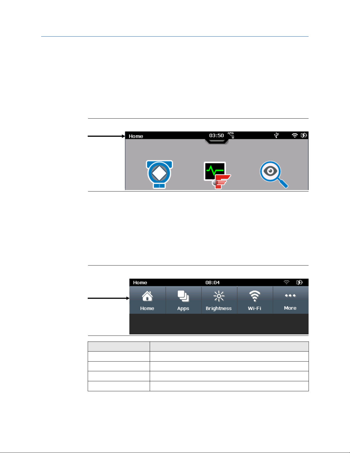
2.9.2
Status bar
The status bar lets you access settings and view information about the Trex unit. The
status bar is displayed on the Home screen and in applications.
The status bar displays the following:
• Title of the screen (Home)
28 User Guide
User Guide AMS Trex Device Communicator overview
September 2021
• Time
• Paired icon
• USB icon
• Wireless icon
• Power module icon
• Pull-down tab
Figure 2-15: Status bar
2.9.3
Related information
Shortcut bar
Shortcut bar
The shortcut bar lets you access additional settings for the Trex unit and the Field
Communicator application.
To view the shortcut bar, tap Settings on the Home screen or tap the status bar.
Figure 2-16: Shortcut bar
Option
Home
Apps
Brightness
Wi-Fi
Description
Close the shortcut bar and return to the Home screen.
View the open applications or close an application.
Adjust the screen brightness.
Configure wireless settings.
User Guide 29

AMS Trex Device Communicator overview User Guide
September 2021
Option Description
More
Access additional menu options and settings, including power
management, date and time, and touchscreen calibration. You can
also modify settings for the Field Communicator application.
2.10 Settings
The Settings option lets you view information about the Trex unit hardware and modify
settings for the Trex unit and applications. To view and modify settings, tap Settings on
the Home screen or the status bar at the top of the screen to view the shortcuts menu.
You can set the following:
• Screen brightness
• Wi-Fi connection
• A name for the Trex unit
• Date and time
2.10.1
2.10.2
• Screen calibration
• Language
• Power management options
• Security management options
• AMS Device Manager Sync
• Field Communicator application settings
• Platform Communications
View all open applications
You can have multiple applications open at one time. However, some applications may
not be able to run simultaneously because they use the same Trex hardware. (An error
message is displayed when this occurs.)
Procedure
1. Tap Settings or the status bar at the top of the screen.
2. Tap Apps.
All open applications are displayed.
Close an application
You can close an application by tapping Exit in the application, or you can use the Settings
to close it.
Procedure
1. Tap Settings or the status bar at the top of the screen.
2. Tap Apps.
30 User Guide
User Guide AMS Trex Device Communicator overview
September 2021
All open applications are displayed.
3. Select the X next to the application name.
2.10.3 Change the screen brightness
Procedure
1. Tap Settings or the status bar at the top of the screen.
2. Tap Brightness.
3. Use the slider to change the brightness.
2.10.4 Wireless communication
The Trex unit can connect to wireless networks to synchronize data on AMS Trex with AMS
Device Manager. You can enable or disable wireless communication at any time.
When the wireless radio is turned on, the wireless icon displays in the status bar. The Wi-Fi
option in Settings displays a list of wireless networks in range, as well as the ability to
specify an IP address, if your network does not contain a DHCP server to automatically
assign an IP address to the Trex unit. You can specify an IP address and a subnet mask, if
required. Contact your network administrator for details.
Note
The Trex unit cannot connect to a wireless network that requires you to enter log in
information on a website.
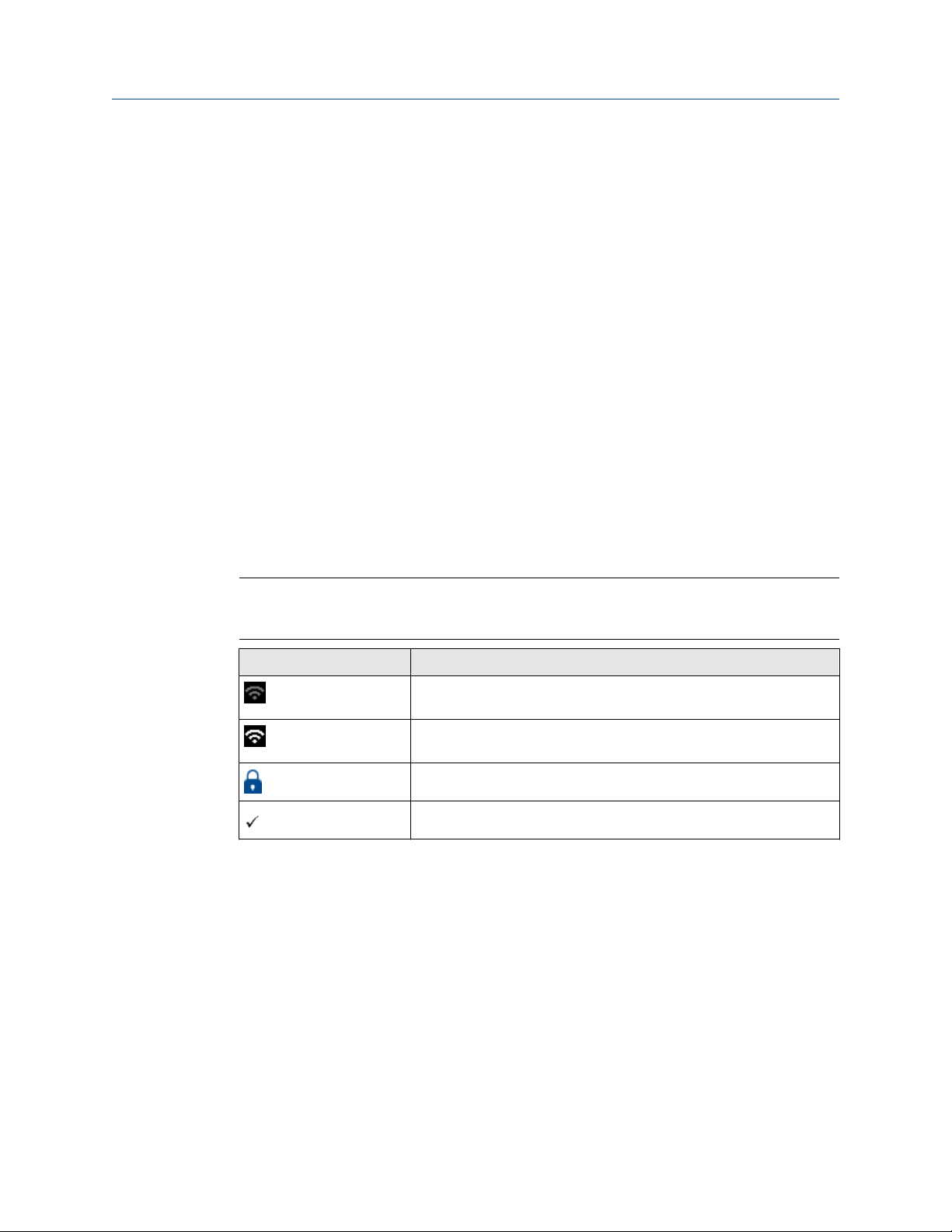
Icon
Individual wireless networks in-range, or previously connected, will appear on the Wireless
Networks screen. You can view the network SSID, security, profile (whether network
configuration has been saved for future use), signal strength, and current connection
status.
You can disconnect from a wireless network by sliding Wireless Networks to off,
connecting to another network, or choosing Forget on a connected Wireless network.
Meaning
(status bar only) Wireless is turned on, but the Trex unit is not
connected to a network.
Wireless is enabled and the Trex unit is connected to a network with a
strong signal. The icon changes based on the signal strength.
Wireless network requires authentication to connect.
The currently connected network
Enable or disable wireless communication
Procedure
1. Tap Settings or the status bar at the top of the screen.
2. Tap Wi-Fi.
User Guide 31
AMS Trex Device Communicator overview User Guide
September 2021
3. Tap the Wireless Networks option to enable or disable wireless.
Connect the Trex unit to a broadcasting wireless network
Note
The Trex unit cannot connect to a wireless network that requires you to enter log in
information on a website.
Procedure
1. Tap Settings or the status bar at the top of the screen.
2. Tap Wi-Fi.
3. Ensure the Wireless Networks option is set to ON.
The wireless communication is enabled.
4. Tap the network you want to connect to. You can tap to the right or left of the
network name.
5. Tap Connect, and enter credentials if prompted.
Once connected, a checkmark is displayed next to the name of the network to show
it is connected to the network. The wireless icon in the status bar changes to .
Connect the Trex unit to a non-broadcasting wireless network
You can connect to a wireless network that is non-broadcasting by manually entering
required options when in range.
Procedure
1. Tap Settings or the status bar at the top of the screen.
2. Tap Wi-Fi.
3. Ensure the Wireless Networks option is set to ON.
This enables the wireless radio in the Trex unit.
4. Tap Add Wi-Fi Network....
5. Edit the following options as needed. You may need assistance from your network
administrator.
Option
Network SSID The name of the wireless network.
Security The type of security used for the wireless network.
6. Tap Connect.
Depending on the network security, you may need to enter credential information
when the network is in range.
Description
32 User Guide

User Guide AMS Trex Device Communicator overview
September 2021
Enter a network address for an AMS Trex unit
You can specify how an AMS Trex unit connects to your network. Enter DHCP to allow a
network address to be assigned, or Static to specify an IP address and/or Subnet Mask.
Note
Contact your network administrator before changing settings. Ensure the port you are
sending to is configured to receive AMS Trex data.
Procedure
1. Tap Settings.
2. Tap Wi-Fi, and turn on Wireless Networks.
3. Tap IP Address, and tap the IP Address Assignment line to change from DHCP to
Static.
4. Enter an IP Address, and/or Subnet Mask.
5. Tap OK.
Forget a wireless network
Forgetting a wireless network prevents the Trex unit from automatically reconnecting to
it. You can forget a network to which you are currently connected, or one where you have
entered credentials.
Procedure
1. Tap Settings or the status bar at the top of the screen.
2. Tap Wi-Fi, then tap the network.
3. Tap Forget.
The network disconnects. If there is data that has not been synchronized with AMS
Device Manager, you are prompted to confirm before disconnecting.
Change the default connection port
AMS Trex communicates with wireless networks at port 8009. If your network uses this
port or restricts access to it, AMS Trex may not be able to communicate with the network.
Contact your network administrator for details.
Procedure
1. Tap Settings → Platform Communications.
2. Tap to change the default, and enter a port number.
Postrequisites
If you change the default port for one AMS Trex unit, Emerson recommends setting all
AMS Trex units to exchange data on that port. All AMS Device Manager stations that
synchronize with AMS Trex units must also have the same port number. See AMS Device
Manager Release Notes for details on changing port settings on the PC.
User Guide 33

AMS Trex Device Communicator overview User Guide
September 2021
2.10.5 View information about the Trex hardware and operating system
You can view the information about the Trex unit, including the name, serial number,
support contract, operating system, open-source licenses, and the MAC address.
Procedure
1. Tap Settings or the status bar at the top of the screen.
2. Tap More → About.
3. Tap OK.
2.10.6 Enter a name for the Trex unit
You can enter a name to uniquely identify the Trex unit. This is helpful if you have multiple
Trex units at your site. By default, the Trex unit is named "TrexXXXXXXXXXXXX" where the
Xs are the serial number. This name is displayed in Upgrade Studio or AMS Device
Manager.
2.10.7
2.10.8
Procedure
1. Tap Settings or the status bar at the top of the screen.
2. Tap More → About.
3. Tap Name.
4. Enter a new name up to 20 characters.
5. Tap OK.
View the application version number
You can view the version numbers for all the installed applications.
Procedure
1. Tap Settings or the status bar at the top of the screen.
2. Tap More → Installed Applications.
The version numbers for all installed applications are displayed.
3. Tap OK to close the screen.
Set the time and date
Note
When you connect the Trex unit to a PC or a wireless network, the Trex unit updates to use
the same time as the PC or wireless network.
Procedure
1. Tap Settings or the status bar at the top of the screen.
2. Tap More → Date & Time.
34 User Guide

User Guide AMS Trex Device Communicator overview
September 2021
3. Edit the following options as needed.
Option Description
2.10.9
Auto adjust daylight
savings
Date Enter the date.
Date Format Select the format for the date. You can select DD/MM/YYYY
Time Enter the time.
Time Format Select the 12 hour or 24 hour format.
Time Zone Select the time zone.
4. Tap OK.
Enable or disable the Trex unit from automatically adjusting
the time for daylight saving time.
or YYYY/MM/DD.
Calibrate the touchscreen
If the touchscreen seems inaccurate, you can recalibrate it.
Procedure
1. Note
If your Trex unit is unresponsive to the touch screen, you can navigate to this menu
with the arrow keys, then initiate the calibration.
Tap Settings or the status bar at the top of the screen.
2. Tap More → Display → Calibrate touch screen.
3. Tap the screen as indicated.
4. Tap OK.
2.10.10
User Guide 35
Set the language on Trex
Changing the display language requires the AMS Trex unit to be rebooted. Make sure you
have no outstanding changes before changing the display language.
Procedure
1. Tap the toolbar at the top of the screen.
2. Tap More → Language.
3. Select a language, and tap OK.
The AMS Trex unit reboots and the new language is displayed. Not all applications
support all available languages. The Trex unit does not support entering characters
in non-Latin languages.

AMS Trex Device Communicator overview User Guide
September 2021
2.10.11 View the amount of available memory
Procedure
1. Tap Settings or the status bar at the top of the screen.
2. Tap More → Memory Management.
2.10.12 Power management
You can configure options to conserve power usage.
Power management option Description
Dim Display (Backlight) timer Dim the backlight after a period of inactivity.
Suspend timer Turn off the backlight after a period of inactivity. Device
communication and power are not interrupted.
Note
If the Suspend timer is enabled, the Shut Down timer is ignored.
Disable the suspend timer by setting the timer to Never to
maximize the battery charge of your Trex unit.
Shut Down timer Shut down the Trex unit after a period of inactivity.
When the AC adapter is connected to the power module, all the timers are disabled. It is
recommended to connect your Trex unit to the AC Adapter when not in use to ensure full
charge of the power module and maximize the life of the battery.
Note
The timers are cumulative. For example, if you set the Dim Display (Backlight) timer to 5
minutes, the Suspend timer to Never, and the Shut Down timer to 10 minutes, the Trex
unit shuts down after 15 minutes of inactivity.
Enter or exit suspend mode
Suspend mode is similar to standby mode on a phone. The screen is turned off, but all
connectivity is maintained. If the Trex unit is powering a device before entering suspend, it
continues to power and communicate with the device. If a Trex unit is connected to a
network, it remains connected in suspend mode. You can put the Trex unit in suspend
mode, or wait for the suspend timer to expire.
When in suspend mode, the Trex unit shuts down if there is no activity (key presses) after a
specified amount of time. Use the Turn off after option on the Power Management
screen to specify this time.
Procedure
1. To enter suspend, do one of the following:
• Quickly press the power button, and then tap Suspend.
• Tap Settings or the status bar at the top of the screen, and tap More → Power
Management → Suspend.
36 User Guide

User Guide AMS Trex Device Communicator overview
September 2021
• Wait until the suspend timer expires.
2. To leave suspend, quickly press the power button or tap the touchscreen.
Related information
Set the suspend timer
Set the backlight timer
To conserve power, set the backlight timer to automatically dim the backlight after a
specified period of inactivity.
The timer is enabled only when the AC adapter is not connected to the Trex unit.
Procedure
1. Tap Settings or the status bar at the top of the screen.
2. Tap More → Power Management → Dim display after.
3. Select the number of minutes.
The default is 5 minutes.
4. Tap OK.
Set the suspend timer
To conserve power, set the suspend timer to automatically enter suspend mode after a
period of inactivity, such as no key presses. Suspend is similar to the standby mode on a
phone. The Trex unit shuts down if there is no activity (key presses) after a specified
amount of time. Use the shut down timer to specify this time.
The timer is enabled only when the AC adapter is not connected to the Trex unit.
Procedure
1. Tap Settings or the status bar at the top of the screen.
2. Tap More → Power Management → Suspend after.
3. Select the number of minutes.
The default is set to Never.
4. Tap OK.
Set the shut down timer
To conserve power, set the shut down timer to automatically shut down the Trex unit after
a period of inactivity, such as no key presses or taps on the screen.
The timer is enabled only when the AC adapter is not connected to the Trex unit.
Procedure
1. Tap Settings or the status bar at the top of the screen.
2. Tap More → Power Management → Turn off after.
3. Select the number of minutes.
The default value is set to 30 minutes.
User Guide 37

AMS Trex Device Communicator overview User Guide
September 2021
4. Tap OK.
2.10.13 Enable or disable automatically connecting to HART devices
If this option is enabled, the Field Communicator application searches for and
automatically connects to an externally-powered HART device at address zero and displays
its device menu. This makes the connection process faster. If this option is disabled, the
Field Communicator application polls addresses zero and 63 and displays the Device List,
so you can select a device from the list or change polling options from the My Device Not
Found button.
You may want to disable this option in the following situations:
• The Trex unit is connected to a multi-drop HART loop, and you want to configure a
device at another address.
• The Trex unit is connected to a transmitter at address zero with a THUM adapter.
Otherwise, the Trex unit may automatically connect to the transmitter at address zero,
and would not allow you to connect to the THUM adapter.
• You want to configure multiple THUM adapters and do not want to adjust the polling
option.
Procedure
1. Tap Settings or the status bar at the top of the screen.
2. Tap More → Field Communicator App Settings.
3. Tap Auto-Connect to enable or disable the option.
4. Tap OK.
2.10.14
Enable Diagnostic Logging
Procedure
Note
You should only enable Diagnostic Logging when directed by Emerson service personnel.
From Settings → Field Communicator App Settings tap Diagnostic Logging to ON.
2.11 Applications on the Trex unit
The Home screen displays all the applications installed on the Trex unit. Open applications
by tapping the icon on the Home screen.
Field Communicator, Settings, and Trex Help applications do not require activation to
work. Other applications on the Trex unit may be disabled until you activate the Trex unit.
You can use Upgrade Studio to activate the Trex unit. Other applications may be disabled
because you did not purchase a license for the functionality, or the Trex unit does not have
the required communication module.
38 User Guide

User Guide AMS Trex Device Communicator overview
September 2021
You can run some applications simultaneously on the Trex unit, while other applications
may require the same hardware and cannot run at the same time. An error message is
displayed on the screen when that occurs. Applications, such as the Field Communicator
application and Settings, can run simultaneously. To switch between applications that can
run simultaneously, tap the status bar at the top of the screen and tap Apps. You can then
select the open application you want to view and use.
You can purchase new applications or get updates to applications from Upgrade Studio.
See the Upgrade Studio Help for more information.
Related information
Home screen
View the application version number
2.11.1
2.11.2
Activation
After you receive the Trex unit, it is recommended that you activate it using Upgrade
Studio. Activation allows you to receive and install updated content on the Trex unit, as
well as give you access to additional applications. Some applications may require you to
purchase a license.
A reminder message is displayed each time you power on the Trex unit until activation is
completed.
Close an application
You can close an application by tapping Exit in the application, or you can use the Settings
to close it.
Procedure
1. Tap Settings or the status bar at the top of the screen.
2. Tap Apps.
All open applications are displayed.
3. Select the X next to the application name.
2.12 USB communication
The Trex unit supports USB communication with PCs. The Trex unit has a micro USB port
on the top left corner of the unit. The required USB driver is automatically installed with
Upgrade Studio and AMS Device Manager. You can:
• transfer files to the Trex unit, using Upgrade Studio
• pair the Trex unit with an AMS Device Manager system to synchronize data
To help ensure proper communication between the Trex unit and the PC, do not use a USB
2.0 cable that is longer than 2 meters. Do not connect more than one Trex unit to an AMS
Device Manager station at one time.
User Guide 39

AMS Trex Device Communicator overview User Guide
September 2021
CAUTION
• Remove the USB cable from the Trex unit before connecting to a device.
• Do not use USB communication in a hazardous area.
2.13 Synchronizing AMS Trex data with AMS Device Manager
AMS Trex provides the ability to connect to AMS Device Manager and update the AMS
Device Manager database with device data. The initial operation that enables this is a
pairing of an AMS Trex unit with a single AMS Device Manager station.
By default, synchronization happens automatically when AMS Trex is connected to a
paired AMS Device Manager station using USB, or when it is connected to a Wi-Fi network
that can communicate with an AMS Device Manager Server Plus. Synchronization occurs
when the devices match in both systems (by manufacturer, device type, device revision,
and protocol version).
Note
AMS Trex cannot communicate wirelessly with an AMS Device Manager system whose
ServerPlus name is not a valid hostname (for example, named with an IP address).
In the AMS Device Manager Sync screen in Settings, AMS Trex shows:
• The name of the AMS Device Manager station to which the unit is paired, along with an
option to unpair. A Trex unit can only be paired with one AMS Device Manager system
at a time.
• An indication of whether data is pending to be synchronized to AMS Device Manager
• The time of the last synchronization
After a Trex unit has been paired to an AMS Device Manager system, synchronization
happens automatically when:
• A Trex unit is connected to the AMS Device Manager station by USB OR
• A Trex unit wireless radio is on, and is connected to a wireless access point
Note
AMS Device Manager will synchronize with as many paired AMS Trex units as are
connected to wireless, and in-range. An Audit Trail entry indicates each pairing, unpairing,
and synchronization with a specific Trex unit.
40 User Guide

User Guide AMS Trex Device Communicator overview
September 2021
2.13.1 Synchronize AMS Trex data to AMS Device Manager using USB
Prerequisites
CAUTION
Remove the USB cable from the Trex unit before connecting to a device.Do not use USB
communication in a hazardous area.
AMS Device Manager is licensed to communicate with AMS Trex.
AMS Device Manager is paired with the AMS Trex Device Communicator being
synchronized.
Procedure
1. Connect the micro-USB end of the cable to the AMS Trex unit.
2. Connect the USB to the AMS Device Manager station.
AMS Trex begins downloading Audit Trail events to the AMS Device Manager Audit
Trail.
2.13.2
Note
If the AMS Trex unit Wireless is turned on and connected to a network containing
the paired AMS Device Manager station, you do not need to sync using USB. Any
data that is new since the last synchronization will automatically connect and
download to the AMS Device Manager database.
Pair an AMS Trex unit with an AMS Device Manager station
CAUTION
Remove the USB cable from the Trex unit before connecting to a device.
CAUTION
Do not use USB communication in a hazardous area.
Prerequisites
The user pairing the AMS Trex unit to AMS Device Manager must have the Manage
Connections permission in User Manager.
AMS Device Manager is running, and the Device Explorer or Device Connection View is
displayed. Pairing can only be done from the AMS Device Manager station, not from the
Trex unit. Only one concurrent USB Trex connection to an AMS Device Manager station is
supported.
User Guide 41

AMS Trex Device Communicator overview User Guide
September 2021
Procedure
1. Connect the microUSB cable to the AMS Trex unit, and then connect the USB to an
AMS Device Manager station.
2. In AMS Device Manager, expand the AMS Trex Units node to display a list of AMS
Trex units.
3. Right-click the unpaired icon, and select Pair Trex Unit.
The icon changes to indicate the unit is paired, and an Audit Trail event is created to
indicate the pairing.
Related information
Unpair an AMS Trex unit
2.13.3 Unpair an AMS Trex unit
You can unpair a Trex unit from the AMS Device Manager software or from the Trex unit.
To assure device data is not lost, you should unpair from the AMS Device Manager UI.
Unpair from an AMS Device Manager station
From AMS Device Manager, connect the microUSB to the Trex unit, and then connect the
USB to an AMS Device Manager system where it is currently paired. Right-click the unit and
choose Unpair Trex Unit.
Pairing an AMS Trex unit to another AMS Device Manager station will also unpair it from
the current station.
Unpair from an AMS Trex unit
If you are unable to unpair from the AMS Device Manager station, you can also unpair from
the Trex unit itself:
Procedure
1. Connect the microUSB to the Trex unit, and then connect the USB to an AMS Device
Manager system where it is currently paired.
2. On the AMS Trex unit, tap Settings or the status bar at the top of the screen.
3. Tap More → AMS Device Manager Sync.
4. Tap X.
You will be prompted to confirm unpairing. If any data is in the process of
synchronizing, it will be lost. If the AMS Trex unit is not connected to AMS Device
Manager when unpairing, any data on the unit will be lost when re-connected.
Note
Pairing a Trex unit is only done from an AMS Device Manager station.
Related information
Pair an AMS Trex unit with an AMS Device Manager station
42 User Guide

User Guide AMS Trex Device Communicator overview
September 2021
2.14 Upgrade Studio
Upgrade Studio is a PC application that lets you update the Trex units at your site with
new/updated device descriptions, applications, firmware, and operating systems. You can
download the updates to Upgrade Studio, or you can import the updates into Upgrade
Studio from a DVD or other physical media, network, or local drive. (You can use Upgrade
Studio with or without an internet connection.)
After the updates are downloaded or imported into Upgrade Studio, you can transfer and
install the updates onto the connected Trex unit.
Upgrade Studio also provides a link to a website where you can purchase new applications,
accessories, or Trex units or identify the sales channel for your area.
Upgrade Studio lets you:
• Create and use your Trex online user account to activate the Trex unit, download
updates, view support contract information, or access the online store, if it is available
in your area.
• Activate the Trex unit. (Activation is required to install updates and access additional
features.)
• Download new or updated device descriptions, applications, firmware, and operating
systems for the Trex unit.
• Import new or updated device descriptions, applications, PDF files, firmware, and
operating systems for the Trex unit into Upgrade Studio. Use the Import option if the
PC does not have an internet connection and cannot download updates. (You can also
import Trex synchronization files or updates to Upgrade Studio.)
• Transfer and install the updates onto the Trex unit.
• Download and install a newer version of Upgrade Studio.
• View the files that are installed on the Trex unit and additional information about the
Trex unit.
• Enable security on your Trex unit.
If you do not have access to a DVD drive to install Upgrade Studio, visit the support page
to download the software.
User Guide 43

AMS Trex Device Communicator overview User Guide
September 2021
2.14.1 Connect the Trex unit to Upgrade Studio using USB
Prerequisites
CAUTION
• Remove the USB cable from the Trex unit before connecting to a device.
• Do not use USB communication in a hazardous area.
• Upgrade Studio cannot connect to multiple Trex units at one time. Only one
connection via USB is supported.
• To help ensure proper communication between the Trex unit and the PC, do not use a
USB 2.0 cable that is longer than 2 meters.
Procedure
1. Ensure the Trex unit is powered on.
2. Connect the microUSB cable to the top of the Trex unit, and then to the PC where
Upgrade Studio is installed.
2.14.2
Note
The USB driver is installed when you install Upgrade Studio.
3. In Upgrade Studio, click Activate Units or Install Updates.
4. If you do not see the Trex unit, select Show All Trex units from the drop-down bar.
Upgrade Studio connects to the Trex unit and the icon appears on the
screen.
Create a Trex online user account
Upgrade Studio provides a link to a website to create a user account. You need a user
account to:
• Activate the Trex unit. (A user account is needed for activation when Upgrade Studio
has an internet connection.)
• Download updates for the Trex unit or Upgrade Studio.
• View the support contract information for the Trex unit.
• Access the Trex online store, if it is available in your area.
Procedure
1. In Upgrade Studio, click Login → Create an Account.
A web browser opens.
2. Enter your information.
3. Click Submit.
4. Wait for notification via email that the user account is available.
44 User Guide

User Guide AMS Trex Device Communicator overview
September 2021
5. Follow any additional steps described in the notification email.
2.14.3 Activate the Trex unit
Prerequisites
Create a user account in Upgrade Studio.
The Trex unit displays an activation reminder message each time you power on the Trex
unit until it is activated. Activation enables the full functionality on the Trex unit and
associates the Trex unit with your user account/company.
Upgrade Studio can activate the Trex unit with or without an internet connection. The
procedure below is for PCs with an internet connection.
Procedure
1. Connect the Trex unit to the PC where Upgrade Studio is installed.
2. In Upgrade Studio, click Activate Units.
3. Click Login.
4. Enter your username and password, if prompted, and click Login.
Logging in enables Upgrade Studio to retrieve the correct activation code for the
Trex unit. If you do not log in, you need to click the "Don't have an activation code?"
link to request an activation code. When you receive the activation code, enter or
copy/paste the code onto the Activate Units screen.
5. Click the Trex unit displayed on the left side of the screen.
6. Click Activate.
A message confirming the activation was successful is displayed.
2.14.4
Activate the Trex unit without using an internet connection
Prerequisites
To activate the Trex unit without using an internet connection, request an activation code
by emailing Emerson at WWCS.CustServ@emerson.com or calling 888-367-3774 option 2
(U.S. and Canada) or +63.2.702.1111 (worldwide) and providing the serial number. The
serial number is located on the bottom of the Trex unit, but you can also access the serial
number by connecting the Trex unit to Upgrade Studio and then hovering the cursor over
the Trex unit icon.
Procedure
1. Connect the Trex unit to the PC where Upgrade Studio is installed.
2. In Upgrade Studio, click Activate Units.
3. Click the connected Trex unit that is displayed on the left side of the screen.
4. Enter or copy/paste the activation code you received.
5. Click Activate.
A message confirms the activation was successful.
User Guide 45

AMS Trex Device Communicator overview User Guide
September 2021
6. Click More → Export.
7. Under Trex Synchronization Files, click Show Details.
8. Select one or more Trex synchronization files to export.
9. Click Export.
10. Select a location to save the Trex synchronization file, and click OK.
11. If you are not using the air-gap deployment, email the exported Trex
synchronization file to Emerson at WWCS.CustServ@emerson.com.
12. If you are using the air-gap deployment, do the following:
a) Open Upgrade Studio on the PC that has an internet connection.
b) Transfer the Trex synchronization file to that PC.
c) Click More → Import Package.
d) Browse to the location that has the Trex synchronization file, and click OK.
e) Click Import.
f) Click OK.
g) Log in with your username and password. Upgrade Studio uploads the Trex
synchronization file.
2.15 AMS Trex Security
Upgrade Studio lets you manage secure access to Trex units. You can configure a Trex unit
to have Local, Enterprise, or no security scheme.
Initial setup
An Upgrade Studio user can initially set the security of a Trex unit to either Local or
Enterprise security. Subsequently, only this user can change the security scheme of the
Trex unit. Other users may change the security scheme once the first user changes the
security to None.
Local security
Local security only allows user accounts created on the Trex unit to access it.
When local security is selected, an Administrator user must be created on the Trex unit.
This Administrator user can create or delete other users on the Trex unit. The
Administrator user is only deleted when the security of the Trex unit is set to None using
Upgrade Studio.
Enterprise security
Enterprise security requires Windows Active Domain credentials to access a Trex unit.
When enterprise security is selected, a Windows domain name, wireless network service
set identifier (SSID), username, and password is required the first time the Trex unit is
used. A wireless network with WPA2-Enterprise security is required.
46 User Guide

User Guide AMS Trex Device Communicator overview
September 2021
Near-field communication (NFC) card access
You can use an NFC card, a technology used in badge entry systems or payment cards, to
control access to a Trex unit using the Security Management settings. You must first
enable a security scheme on the Trex unit before pairing it with an NFC card. Pairing the
Trex unit with an NFC card requires you to enter a PIN. Only one NFC card and PIN
assignment is supported for a Trex unit user.
The Trex unit supports NXP NTAG21x series NFC cards. The NTAG21x series are 2nd
generation NFC chips by NXP. The NTAG21x series NFC cards have a unique 7-byte UID
(Serial Number) that Trex units use when pairing a card to a user.
Note
The Trex unit does NOT have security enabled out of the box.
2.15.1
2.15.2
Enable local security for a Trex unit
Procedure
1. Connect the Trex unit to the PC where Upgrade Studio is installed.
2. In Upgrade Studio, select More → AMS Trex Security.
3. Click the Trex unit that is displayed on the left side of the screen.
4. Select Local.
5. Click Change Security Type.
6. Click Yes.
The Trex unit will restart.
7. Click OK.
8. On the Trex unit, create a local administrator by entering a user name and password
and confirming the password.
9. Tap OK.
Note
The local administrator can add or delete other users on the Trex unit.
Enable enterprise security for a Trex unit
Procedure
1. Connect the Trex unit to the PC where Upgrade Studio is installed.
2. In Upgrade Studio, select More → AMS Trex Security.
3. Click the Trex unit that is displayed on the left side of the screen.
4. Select Enterprise.
5. Click Change Security Type.
6. Click Yes.
The Trex unit will restart.
7. Click OK.
8. On the Trex unit, enter the following information:
User Guide 47

AMS Trex Device Communicator overview User Guide
September 2021
• Domain - the Windows domain.
• Network SSID - the wireless network SSID. The wireless network must have
WPA2-Enterprise security enabled.
• User name - the domain user name.
• Password - the password for the domain user name.
9. Tap OK.
2.15.3 Disable security for a Trex unit
Note
Only the Windows user who enabled security using Upgrade Studio can disable security.
Procedure
1. Connect the Trex unit to the PC where Upgrade Studio is installed.
2. In Upgrade Studio, select More → AMS Trex Security.
3. Click the Trex unit that is displayed on the left side of the screen.
4. Select None.
5. Click Change Security Type.
6. Click Yes.
The Trex unit will restart.
7. Click OK.
2.15.4
Note
The Trex unit deletes all user information and NFC card assignments.
Create a local user account
Prerequisites
Local security must be enabled on the Trex unit.
Procedure
1. Log in to the Trex unit using the local administrator account.
2. Tap Settings.
3. Tap Security Management.
4. Tap Add user.
5. Enter a user name and tap OK.
Notes
• The new user can only log in after the Trex unit is restarted.
• The new user will be prompted to enter a password during login.
48 User Guide

User Guide AMS Trex Device Communicator overview
September 2021
Related information
Enable local security for a Trex unit
2.15.5 Delete a local user
Procedure
1. Log in to the Trex unit using the local administrator account.
2. Tap Settings.
3. Tap Security Management.
4. Tap Remove user.
5. Select a user.
6. Tap Yes.
2.15.6
2.15.7
Reset the password of a local user
Procedure
1. Log in to the Trex unit using the local administrator account.
2. Tap Settings.
3. Tap Security Management.
4. Tap Reset Password.
5. Select a user.
6. Tap Yes.
Note
The user will be prompted to enter a new password on the next login.
Pair an NFC card to a user
Prerequisites
Local or enterprise security must be enabled on the Trex unit.
Procedure
1. Log in to the Trex unit.
2. Tap Settings.
3. Tap Security Management.
4. Tap Pair NFC card.
5. Tap the NFC card on the navigation buttons of the Trex unit to scan it.
6. Enter a 4-digit PIN code.
7. Tap OK.
Related information
Enable local security for a Trex unit
User Guide 49

AMS Trex Device Communicator overview User Guide
September 2021
Enable enterprise security for a Trex unit
2.15.8 Remove a paired NFC card
Procedure
1. Log in to the Trex unit.
2. Tap Settings.
3. Tap Security Management.
4. Tap Remove NFC pairing.
5. Tap Yes.
2.16 Transferring files to a PC
When you install Upgrade Studio, the Trex File Transfer Utility is also installed. This
application lets you transfer logging or other files to a PC. Use the USB cable to connect
the Trex unit to the PC where the application is installed. See the Help included with
Upgrade Studio for more information.
2.17 Maintenance and repair
Any maintenance, repair, or replacement of components not listed below must be
performed by specially trained personnel at an authorized service center. You can perform
common maintenance procedures listed below:
• Clean the exterior. Use only a dry, lint-free towel or dampen the towel with an alcohol
or mild soap and water solution.
• Clean the touchscreen.
• Install, remove, or charge the power module.
• Remove and replace the stand.
• Ensure that all exterior screws are sufficiently tightened.
• Ensure the communication terminal recess is free of dirt and debris.
• Install and remove the communication module.
2.17.1
Replace the stand
Procedure
1. Place the Trex unit face down on a level, secure surface.
2. Lift up the stand.
3. Use a Torx® screwdriver to loosen and remove the two screws under the stand.
4. Remove the stand.
5. Place the new stand on the Trex unit.
50 User Guide

User Guide AMS Trex Device Communicator overview
September 2021
6. Insert and tighten the two screws. Do not over tighten the screws. Use 0.5Nm
maximum torque load.
2.17.2 Calibration
Calibration is not supported on the AMS Trex Device Communicator. Voltage, current,
signal, and noise measurements made by the Trex unit are intended for troubleshooting
purposes. NIST standards are not applicable to the AMS Trex Device Communicator.
User Guide 51

AMS Trex Device Communicator overview User Guide
September 2021
52 User Guide

User Guide Field Communicator application
September 2021
3 Field Communicator application
The Field Communicator application lets you configure HART and FOUNDATION fieldbus
devices. (The fieldbus functionality requires a license.) You can do the following:
• Power and connect to a HART transmitter, if the Trex unit has the Device
Communicator Plus communication module. The Trex unit has an internal resistor, so
you do not need to add a loop resistor.
• Power and connect to a HART positioner, if the Trex unit has the Device Communicator
Plus communication module.
• Power and connect to the Smart Wireless THUM™ Adapter, if the Trex unit has the
Device Communicator Plus communication module.
• Power and connect to a FOUNDATION fieldbus device, if the Trex unit has the Device
Communicator Plus communication module. The Trex unit provides power, power
conditioning, and two terminators.
• Connect to an externally-powered HART or FOUNDATION fieldbus device.
• Use the internal resistors in the Trex unit when connecting to an externally-powered
HART transmitter. The internal resistors in the Trex unit temporarily convert an
externally-powered 4-20 mA current loop into a HART loop.
• Save menu items from HART devices to a list of favorites for quick access.
• Simulate a HART or FOUNDATION fieldbus device.
Note
The Field Communicator application can be used with the Device Communicator
communication module or Device Communicator Plus communication module. However,
the Trex unit cannot power a HART or FOUNDATION fieldbus device with the Device
Communicator communication module.
3.1 Open or close the Field Communicator application
Procedure
1. To open the application, tap the Field Communicator icon on the Trex Home
screen.
The Auto-Detect screen is displayed while the Field Communicator application tries
to detect a connected device. If you tap Cancel on the Auto-Detect screen, the Field
Communicator application stops checking for devices and displays the Connect -
Select screen.
2. To close the application, tap Exit if the Connect - Select screen is displayed.
Otherwise, tap Back until that screen is displayed.
User Guide 53

Field Communicator application User Guide
September 2021
3.2 Device interoperability
The Trex unit communicates with many HART and FOUNDATION fieldbus devices
independent of device manufacturer by using Electronic Device Description Language
(EDDL) technology.
Basic testing is performed on all device descriptions. New device descriptions are available
from the Upgrade Studio application or the resource DVD.
3.3 Forward Compatibility rules for saving and sending configurations to AMS Trex
Note
Do not edit configurations on the AMS Trex unit while connected to Configuration
Management.
You can edit offline configurations on the Trex unit according to forward compatibility
rules:
• To edit a configuration with Trex, you must have the proper device description installed
on Trex. The installed device description must match the device type and device
revision of the configuration. If the configuration does not exactly match the device
description on the Trex unit, you cannot save the configuration.
• To send a configuration to a device, you must have the proper device description
installed on Trex. The installed device description must be for the same device type,
and equal to or greater than the device rev of the configuration.
• You cannot save or send configurations when using the generic device description.
3.4 Automatically detect a device
The Field Communicator application can automatically detect a device, without requiring
any input from you. When you open the Field Communicator application or when the
Connect - Select screen is displayed, the Trex unit checks for the most common
connection scenarios and, if possible, detects the connected device and displays the
Device List. You can then select a device and display its device menu. The auto-detect
feature lets you skip the device connection wizard in the Field Communicator application,
which allows for faster connections to devices.
The Field Communicator application can automatically detect:
• A HART device that is on an externally-powered compliant HART loop, and the device is
communicating at address zero.
• A 4-wire HART device that is communicating at address zero. (This may require a
resistor across the HART terminals. Check the device documentation for the proper
connection.)
• A WirelessHART device that is powered by its battery, and the device is communicating
at address zero.
54 User Guide

User Guide Field Communicator application
September 2021
• A powered FOUNDATION fieldbus segment that is actively communicating. The
fieldbus segment must have a host system or a FOUNDATION fieldbus device that is
the Link Active Scheduler (LAS).
While the Trex unit is connecting to the device, the Auto-Detect screen is displayed to
show the status. If you tap Cancel, the Connect - Select screen is displayed and the Trex
unit stops the connection process.
Note
For HART devices, the Field Communicator application can automatically detect and
connect to the device if the Auto-Connect option in the Trex Settings is enabled. If this
option is enabled, the device menu is displayed rather than the Device List.
3.4.1 Automatically connect to a HART device
The Field Communicator application can automatically detect and connect to a HART
device, without requiring any input from you. When you open the Field Communicator
application or when the Connect - Select screen is displayed, the Trex unit checks for the
most common connection scenarios and, if possible, connects to the device and displays
the device menu.
To use the auto-connect feature, ensure the Auto-Connect option is enabled (Settings →
Field Communicator App Settings → Auto-Connect), and the Trex unit is connected to
one of the following:
• A HART device that is on an externally-powered compliant HART loop, and the device is
communicating at address zero.
• A 4-wire HART device that is communicating at address zero. (This may require a
resistor across the HART terminals. Check the device documentation for the proper
connection.)
• A WirelessHART device that is powered by its battery, and the device is communicating
at address zero.
If the Trex unit cannot automatically connect to the device, tap HART on the Connect -
Select screen and follow the prompts from the device connection wizard to connect to the
device.
Note
You can disable the Field Communicator application from automatically connecting to a
device at address zero. If you disable this option, the Trex unit still detects the device at
address zero, but you need to select the device on the Device List to connect and view the
device screens. You may also want to disable this option if the Trex unit is connected to a
transmitter at address zero with a THUM adapter.
3.5 Connect - Select screen
If the Trex unit cannot automatically detect or connect to the device when you open the
Field Communicator application, the Connect - Select screen is displayed. The Connect -
Select screen is the home screen for the Field Communicator application.
You can do the following on the Connect - Select screen:
User Guide 55

Field Communicator application User Guide
September 2021
• Connect the lead set to the Trex unit and to the device to try to automatically detect/
connect to the device. If the device meets the criteria for automatically connecting, the
Trex unit tries to connect to the device.
• Tap HART or Fieldbus to start the device connection wizard and connect to the device.
• Tap HART Offline or Fieldbus Offline to simulate a device.
Figure 3-1: Connect - Select screen
Note
To switch between HART communication and FOUNDATION fieldbus communication, you
must exit and restart the Field Communicator application. After the HART or Fieldbus
Device Lists are displayed, the HART or Fieldbus buttons disappear until you restart the
application.
Option
Power Status
56 User Guide
Description
Detect voltage on the lead set.

User Guide Field Communicator application
September 2021
Option Description
Communication Status
HART
HART Offline
Fieldbus
Fieldbus Offline
Detect if a connected device is communicating with the Trex
unit.
Connect to a live HART device. Tap this option if the Trex unit
could not automatically detect or connect to the device. The
device connection wizard is displayed.
Simulate a connected HART device to become familiar with
the menus before configuring the device in a critical
environment. This option does not require communication
with a device.
Connect to a live FOUNDATION fieldbus device. Tapping
Fieldbus starts the Trex unit's communications if external
power is detected, and the Trex unit assumes the role of
network master (LAS), if no other master exists. The device
connection wizard is displayed. (The Fieldbus option is
displayed only if Trex unit is licensed for FOUNDATION
fieldbus.)
Simulate a connected FOUNDATION fieldbus device to
become familiar with the menus before configuring the
device in a critical environment. This option does not require
communication with a device. (The Fieldbus Offline option is
displayed only if Trex unit is licensed for FOUNDATION
fieldbus.)
To return to the Connect - Select screen from a device screen, press Menu → Disconnect.
Related information
Status when detecting a device
3.6 Device connection wizard
If the Trex unit cannot automatically detect or connect to the device, tap HART or Fieldbus
on the Connect - Select screen to start the device connection wizard. The wizard displays a
set of questions to help you connect to the device. You may see one or more of the
questions below depending on the setup of your device. The questions may appear in a
different order than listed below.
• Do you intend to provide power from the Trex unit? (This is available only if the Device
Communicator Plus communication module is attached to the Trex unit.)
• Is the Trex unit connected to a transmitter or a positioner?
• Do you want to change the polling options?
• Do you want to increase loop resistance? (This enables the internal resistors.)
• Do you want to increase loop current? (This is available for only positioners.)
In the Field Communicator application, the device connection wizard is the only way to
enable the Trex unit to power a device, change the polling options for HART and fieldbus,
enable the internal resistors within the Trex unit, or increase current to positioners.
User Guide 57

Field Communicator application User Guide
September 2021
If the device connection wizard completes its process and cannot connect to the device, a
message is displayed. Tap Cancel to return to the Connect - Select screen to retry the
connection process.
Note
The selections are not saved in the device connection wizard. You need to select the
desired options each time you connect to a device.
Note
If you tap Back during the device connection wizard, the change you made on that screen
is canceled and the previous screen is displayed. For example, if you enabled the Trex unit
to provide power and changed the polling address from 0 to 63 and then tapped the Back
button, the polling address is set to the default value of 0, but the Trex unit still powers the
device. You can also tap Back to return to a previous question and provide a different
answer/selection.
Problems the device connection wizard can detect
The device connection wizard can also identify common wiring problems, including if the
wrong terminals on the Trex unit are used or if a lead set is not connected to the device or
the Trex unit. If a problem is detected, a message describes the problem or a graphic
shows the correct wiring.
The Trex unit continuously monitors the voltage and current at the terminals where the
lead set is connected. the Field Communicator application displays a message if an error is
detected, including if the lead set is removed from the device or Trex unit. For example, if
you try to enable the Trex unit to power a device that already has power, the Field
Communicator application displays a message that voltage was detected and the Trex
power supply is turned off to protect the device and Trex unit.
In some cases, you may be able to override the warning from the device connection
wizard. For example, some devices may hold voltage for several minutes after being
disconnected from the power supply. If you enable the Trex unit to power a device that is
still holding a low voltage (less than 8 volts), a message is displayed that the Field
Communicator application detects low voltage and asks if the Trex unit is connected to a
digital control system's control loop. You can override this warning and apply power if you
are sure the device is not connected to an external power supply.
If the device connection wizard detects a problem, you can fix the issue while the
connection wizard is displayed. The change is updated in the Power Status and
Communication Status sections.
3.7 Status when detecting a device
When the Trex unit tries to detect and connect to a device, the Power Status option and
the Communication Status option on the Connect - Select screen show one of the
following status messages.
Power Status Message
Voltage Detected on HART Typical status for connecting across HART device's
58 User Guide
Description
communication terminals when the device is on an externallypowered loop.
The detected voltage is greater than or equal to 8 volts.
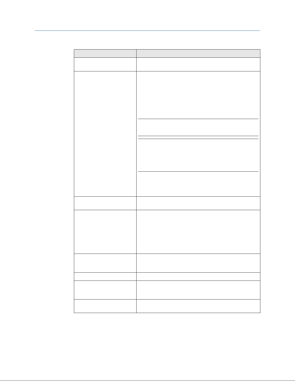
User Guide Field Communicator application
September 2021
Power Status Message Description
Voltage Detected on HART+
pwr
Low Voltage Detected on HART Typical status for connecting:
Low Voltage Detected on HART
+ pwr
The detected voltage is greater than or equal to 8 volts.
• To a 4-wire HART device
• To a WirelessHART device
• Across a resistor
• Across HART control system modules
The detected voltage is between 0.5 and 8 volts.
Note
You may see this status when the AC adapter is attached to the
Trex unit. If low voltage is detected, disconnect the AC adapter.
Note
This message can also appear if the Trex unit connects to a
device that was recently powered. Some devices may hold
voltage for several minutes after being disconnected from its
power supply. The Trex unit provides a warning message that it
detects voltage.
If you try to power a device when this occurs, the Trex unit asks if
you want to ignore the voltage warning and proceed with
sourcing power. If you select Yes, the Trex unit powers the
device.
The detected voltage is between 0.5 and 8 volts.
No Voltage Detected Typical status for connecting:
• An unpowered device.
• To some types of 4-wire HART devices.
• To some types of WirelessHART devices.
This status is also displayed when the lead set is not connected to
a device, or when the Trex unit is connecting to a device.
Voltage Detected on FF Typical status for connecting to an externally-powered fieldbus
segment.
The detected voltage is greater than or equal to 8 volts.
Low Voltage Detected on FF The measured voltage is less than 8 volts.
Voltage Provided from FF pwr The typical status when the Trex unit is powering the
FOUNDATION fieldbus device. The detected voltage is greater
than or equal to 8 volts.
Voltage Provided from HART+
pwr
The typical status when the Trex unit is powering the HART
device. The detected voltage is greater than or equal to 8 volts.
User Guide 59

Field Communicator application User Guide
September 2021
Power Status Message Description
Voltage on Multiple The Trex unit has detected voltage on more than one terminal.
This may be due to the following:
• The AC adapter is attached to the Trex unit and is charging
the power module. Disconnect the AC adapter from the Trex
unit.
• Noise is detected on the network.
• Two lead sets are connected to two different fieldbus
segments or loops. This is not recommended.
Communication Status Description
No Communication The Trex unit has not detected any HART or fieldbus
communication.
Fieldbus Detected The Trex unit has detected FOUNDATION fieldbus
communication.
HART Detected Typical status when the Trex unit detects:
• A HART device in burst mode.
• Active HART communication from the digital control system.
• A response to a polling message sent to the device.
This status may be sporadic and may alternate between HART
Detected and No Communication.
If unexpected communications are detected, remove the AC
adapter to isolate the Trex unit from noise.
3.8 Online menu or Device Dashboard
Depending on the device description (DD) for a device, the first online screen is an Online
menu or a device dashboard menu. All devices show a Menu tab at the bottom of the
screen.
Online menu
An Online menu may display the following options, depending on the device type:
• Device setup
• Primary variable (PV)
• Analog output (AO)
• PV lower range value (LRV)
• PV upper range value (URV)
60 User Guide

User Guide Field Communicator application
September 2021
Figure 3-2: Online menu example
Dashboard menu
A device dashboard menu displays the same parameters as the Online menu, but they are
organized by tab, including:
• Overview - View a graphical representation of the process variable. Tap the More
arrow on the bottom right side of the screen to access additional menu items.
Depending on the device description, the images under "Device" and
"Communications" may be selectable links.
• Service Tools - View and modify options for alerts, variables, and maintenance. For
FOUNDATION fieldbus devices, the Service Tools option lets you edit the device tag
and address, and set the IO block schedule and the link master device. You can also
access the blocks directly from the Block List option on the Service Tools screen.
• Configure - Configure the device parameters.
The options below vary based on the device description for the device.
User Guide 61
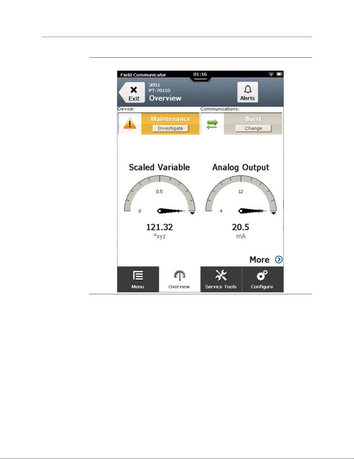
Field Communicator application User Guide
September 2021
Figure 3-3: Dashboard menu example
3.8.1 Device screen layout
In the Field Communicator application, the device screens have four main parts:
62 User Guide

User Guide Field Communicator application
September 2021
Figure 3-4: Sections of a device screen
A. Status bar
B. Application title bar
C. Device menu
D. Application bar
Status bar
Lets you access the settings for the Trex unit and switch to other applications.
Application title bar
Displays the type of device the Trex unit is connected to, the device tag (short tag or long
tag), and the menu title (Online). If you tap the application title bar, a menu is displayed.
Depending on the type of device, the menu lets you view the HART short/long tag or more
information about the device description, including the manufacturer, device type, device
revision, and device description revision. A Back or Exit button is also displayed.
User Guide 63
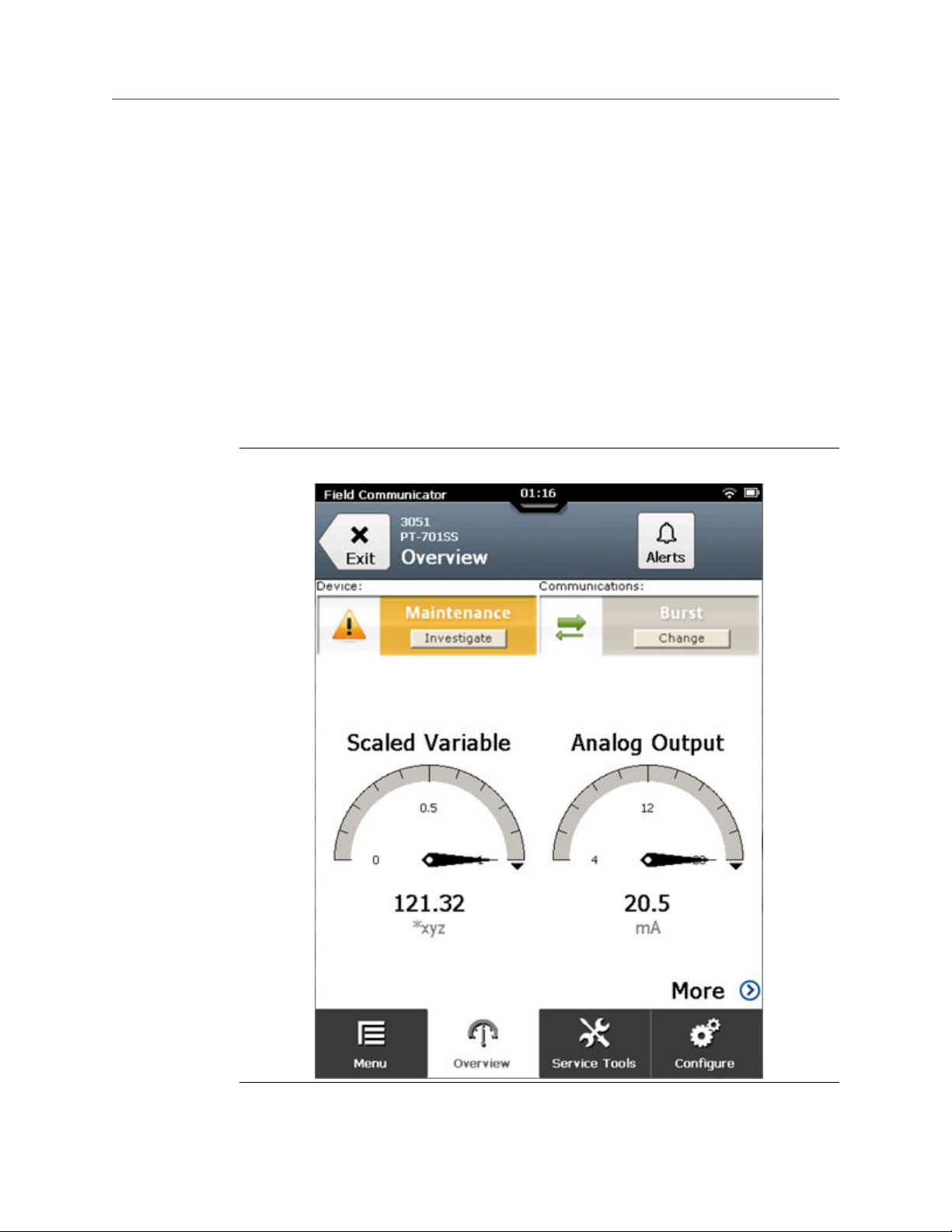
Field Communicator application User Guide
September 2021
Device menu
The menu options for a specific device type and revision. The options displayed will vary
based on the device description. You can press and hold a menu item to display an
additional menu that lets you view Help or add the item to the list of favorites (HART only).
Application bar
Displays the main groups of options for a device. Most devices have an Online option.
Devices that display a device dashboard display Overview, Configure, and Service Tools.
3.8.2 Application bar
The application bar lists the main options for the connected device. Depending on the
device description, you may see a different application bar than the one described below.
See the device documentation for more detailed descriptions of these options.
Figure 3-5: Example of an application bar at the bottom of the screen
64 User Guide

User Guide Field Communicator application
September 2021
Option Description
Menu
Online
Overview
Service Tools
Configure
View the list of favorites for HART devices, simulate a device, or
connect/disconnect a device.
View the process variable and configure device parameters.
(Device dashboard screen only) View a graphical
representation of the process variable. The More option lets
you access the device parameters.
View and modify options for alerts, variables, and
maintenance. For FOUNDATION fieldbus devices, commonly
used parameters are also accessible, including the device tag,
device address, IO block schedule, link master configuration,
and device information.
(Device dashboard screen only) Configure the device
parameters.
3.8.3 Menu screen
The Menu screen lets you connect/disconnect a device, edit and save a configuration,
send a configuration (only for a connected device), set a favorite, or simulate a device.
To access the Menu screen without connecting to a device, tap HART Offline or Fieldbus
Offline on the Connect - Select screen. The Menu screen is also displayed when the Trex
unit is connected to a HART or FOUNDATION fieldbus device. Both the Online screen and
the device dashboard screen display the Menu screen.
User Guide 65
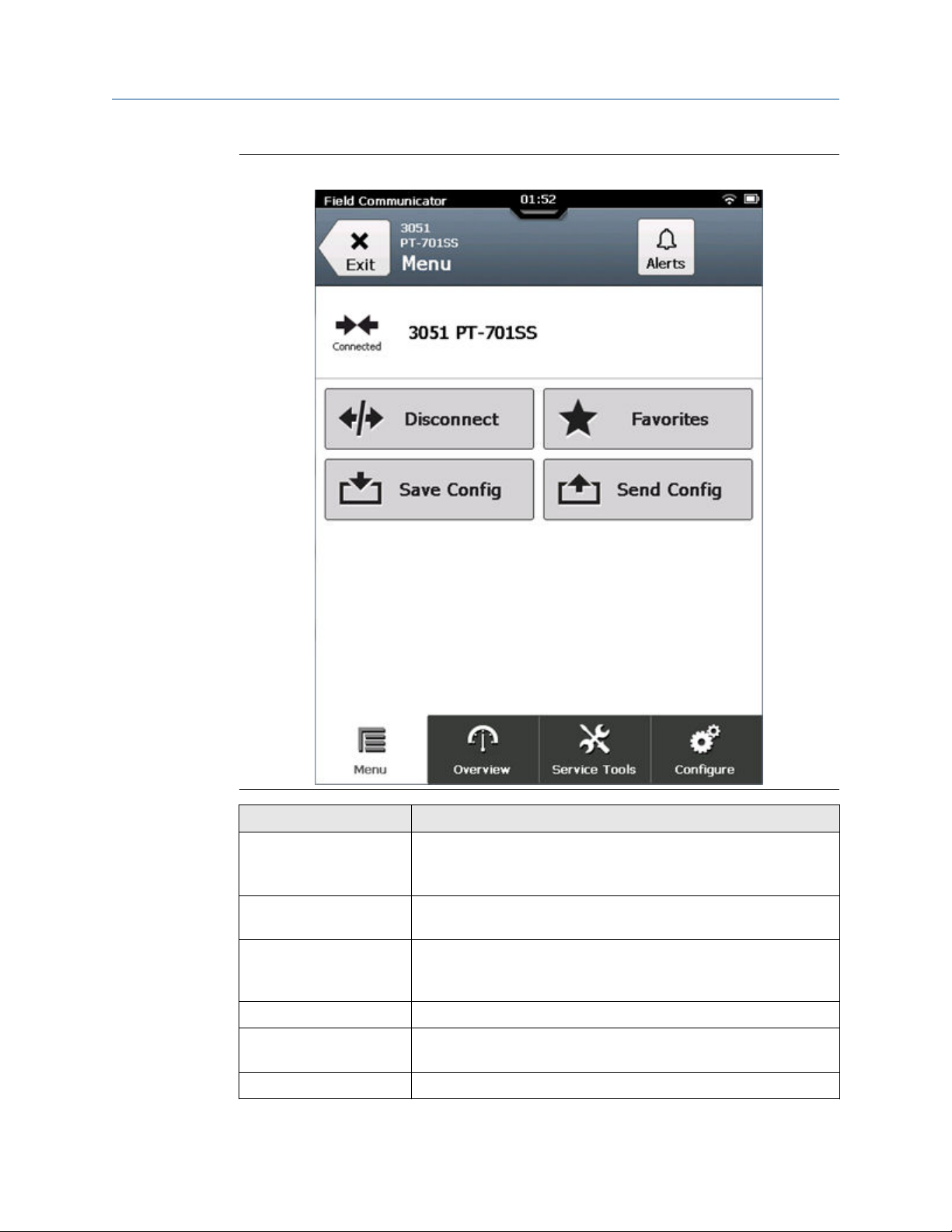
Field Communicator application User Guide
September 2021
Figure 3-6: Menu screen for a connected HART device
Option Description
Connect or Disconnect Tap Connect to return to the Connect - Select screen and connect to
a device. Tap Disconnect to stop communicating with a device. The
Trex unit also stops powering the device when you tap Disconnect.
Favorites
Simulate
Save Config
Send Config
Offline Config
66 User Guide
Save frequently used menu items to a list for quick access. The
Favorites option is available for only HART devices.
Simulate a connection to a live HART or FOUNDATION fieldbus device,
depending on if you selected HART Offline or Fieldbus Offline. This
option is displayed only if a device is not connected to the Trex unit.
Save a configuration for this device to the AMS Trex unit.
Send a configuration to a connected HART device. This option is
displayed only if a device is connected to the Trex unit.
Create or edit a configuration on the AMS Trex unit.

User Guide Field Communicator application
September 2021
You can also connect a device, simulate a device, or edit a configuration from the Menu
screen.
Figure 3-7: Menu screen for no connected HART device
3.9 Icons on the device menus
When the Trex unit is connected to a device, the device menus may have one or more
icons.
User Guide 67

Field Communicator application User Guide
September 2021
Figure 3-8: Device menu with icons
Icon Description
The option is a parameter you can edit, such as the device tag.
The option is a device method, such as a loop test.
The option has a submenu with additional options.
The option is a graph or chart. Charts display a graphic view of variables as they
occur over time.
The option is a gauge chart. A gauge chart formats device data into a view
similar to an analog car speedometer and plots device data varying with time.
The option is a grid.
68 User Guide

User Guide Field Communicator application
September 2021
Icon Description
The option is an image.
No icon The option is a process variable. The process variable value may or may not be
displayed, depending on the device description for the device.
3.10 Connections to HART devices
The Trex unit can communicate with a device from the control room, on the bench, or any
wiring termination point in the loop. Review the HART wiring diagrams to ensure the Trex
unit is correctly connected to the device.
Note
The Trex unit acts as a secondary HART master on a HART loop.
Related information
Internal resistors
3.10.1
HART communication terminals
The Trex unit has communication terminals that enable it to communicate with a HART
device. Insert the lead set into the red and black terminals and connect to a HART device.
Note
The lead set must be used to communicate with a wired or wireless device.
Figure 3-9: HART communication terminals on the Device Communicator
communication module
A. Communicate with an externally-powered HART device
User Guide 69

Field Communicator application User Guide
September 2021
Figure 3-10: HART communication terminals on the Device Communicator Plus
communication module
3.10.2
A. Power and communicate with a HART device.
B. Communicate with an externally-powered HART device.
Related information
Wiring diagrams for HART devices and the Field Communicator application
Power and connect to a HART device
Wiring diagrams for HART devices and the Field Communicator application
The Trex unit can communicate with a device from the control room, on the bench, or any
wiring termination point in the loop. Connect the lead set to the Trex unit and to the
communication terminals on the device or across the resistor.
Below each diagram, a table lists the expected prompts from the device connection wizard
and the answers to complete the connection. The prompts appear only if the Field
Communicator application could not automatically detect or connect to the device.
Note
The Trex unit acts as a secondary HART master on a HART loop.
CAUTION
Remove the USB cable from the Trex unit before connecting to a device.
70 User Guide

User Guide Field Communicator application
September 2021
Figure 3-11: Power and connect to a 2-wire HART transmitter
Note
When the Trex unit powers the HART transmitter, an external resistor is not needed. The
Trex unit uses an internal resistor that is automatically used when you enable the Trex unit
to power the transmitter.
Note
Do not insert a resistor in parallel with either the HART+pwr or HART terminals on the Trex
unit, or in parallel with the device's communication terminals. This may prevent
communications.
Device connection wizard prompts
Do you intend to provide power from the Trex unit?
Are you providing power to a transmitter or positioner?
Change Polling Option? Tap Yes if the device is not at address
Answer
Yes
Transmitter
zero.
User Guide 71

Field Communicator application User Guide
September 2021
Figure 3-12: Connect to a powered
Wireless
HART device (with its battery attached)
CAUTION
Do not use the Trex unit to power a WirelessHART device. Providing power to a
WirelessHART device may damage the device.
Device connection wizard prompts Answer
Do you intend to provide power from the Trex unit?
Leads are attached to:
No
Transmitter
Change Polling Option? Tap Yes if the device is not at address
zero.
Figure 3-13: Connect to an externally-powered 2-wire HART transmitter
If the transmitter is at address zero, the Trex unit may automatically detect and connect to
the device without any prompts from the device connection wizard.
A — Voltage source
Device connection wizard prompts
Do you intend to provide power from the Trex
unit?
Answer
No
72 User Guide

User Guide Field Communicator application
September 2021
Device connection wizard prompts Answer
Leads are attached to:
Change Polling Option? Tap Yes if the device is not at address zero.
Transmitter
Figure 3-14: Connect to an externally-powered 2-wire HART transmitter and use the
Trex internal resistor
Note
The Trex unit must be connected in series with the transmitter to use the internal resistor.
Do not put more than 25V DC on the circuit.
A — Voltage source
Device connection wizard prompts
Do you intend to provide power from the
Trex unit?
Leads are attached to:
Change Polling Option? Tap Yes if the device is not at address zero.
Increase loop resistance? Tap Yes to enable the internal resistor.
Answer
No
Transmitter
User Guide 73
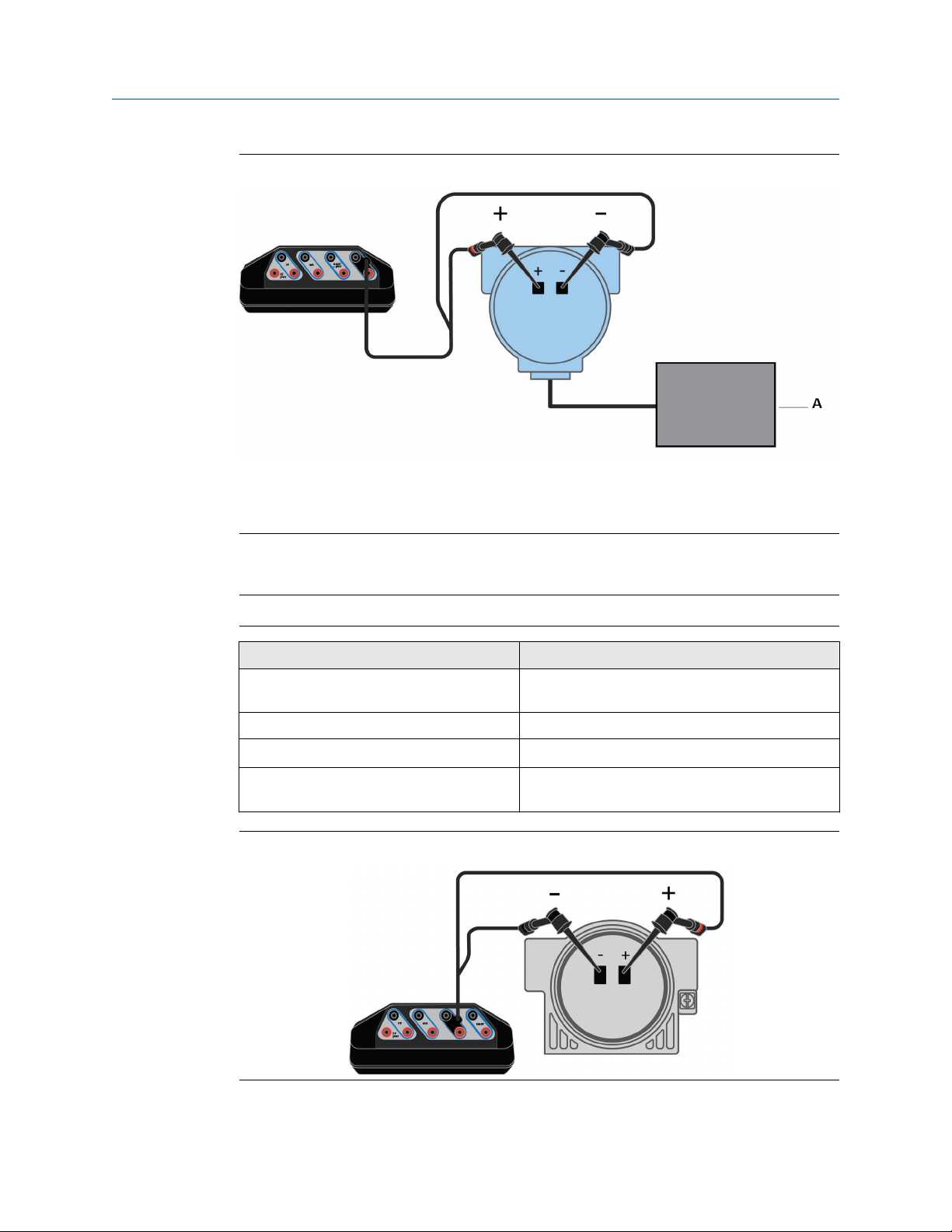
Field Communicator application User Guide
September 2021
Figure 3-15: Connect to a 4-wire HART transmitter
If you have a 250 Ohm resistor, you can insert it in between the device terminals and
connect the lead set across the resistor. Otherwise, you can enable the internal resistor in
the device connection wizard.
Note
Ensure you review the device documentation for connecting/setting up HART
communication. Devices may have different terminals or requirements.
A — Voltage source
Device connection wizard prompts
Do you intend to provide power from the
Trex unit?
Leads are attached to:
Change Polling Option? Tap Yes if the device is not at address zero.
Increase loop resistance? Tap Yes if there is no external resistor between the
Answer
No
Transmitter
device terminals.
Figure 3-16: Power and connect to a HART positioner
74 User Guide
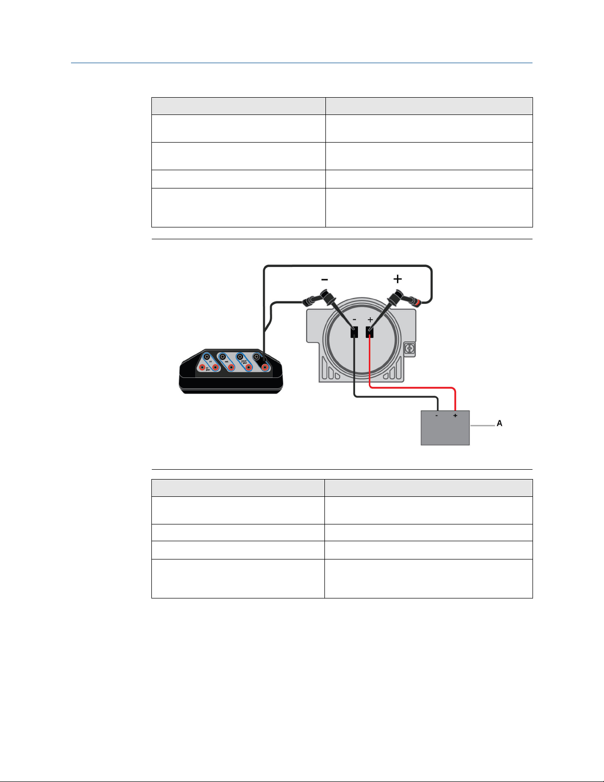
User Guide Field Communicator application
September 2021
Device connection wizard prompts Answer
Do you intend to provide power from the
Trex unit?
Are you providing power to a transmitter or
positioner?
Change Polling Option? Tap Yes if the device is not at address zero.
Increase loop current? Tap Yes to increase the current from 4 mA to
Yes
Positioner
another value, if the device did not initially
communicate.
Figure 3-17: Connect to an externally-powered HART positioner
A — Current source
Device connection wizard prompts
Do you intend to provide power from the
Trex unit?
Leads are attached to:
Change Polling Option? Tap Yes if the device is not at address zero.
Increase loop current? Tap Yes to increase the current from 4 mA to
Answer
No
Positioner
another value, if the device did not initially
communicate.
Related information
HART communication terminals
Connect to an externally-powered HART device
Power and connect to a HART device
Internal resistors
User Guide 75

Field Communicator application User Guide
September 2021
3.10.3 Wiring diagrams for the Smart Wireless THUM™ Adapter and the Field Communicator application
Below each diagram, a table lists the expected prompts from the device connection wizard
and the answers to select to complete the connection.
If you are using a WirelessHART adapter that is not the Smart Wireless THUM adapter,
review its documentation before connecting the Trex unit.
Note
• Ensure you review the documentation included with the THUM adapter for additional
information.
• The Trex unit acts as a secondary HART master on a HART loop.
CAUTION
Remove the USB cable from the Trex unit before connecting to a device.
Figure 3-18: Power the THUM adapter without a device attached and use 250 Ohm
resistor
Connect the lead set to the red and black wires.
Device connection wizard prompts
Do you intend to provide power from the Trex unit?
Are you providing power to a transmitter or positioner?
Change Polling Option? Tap Yes and select the address for the
Answer
Yes
Positioner
Select Positioner because the Trex unit
needs to control/limit current due to
the lower value of the resistor.
THUM adapter.
76 User Guide
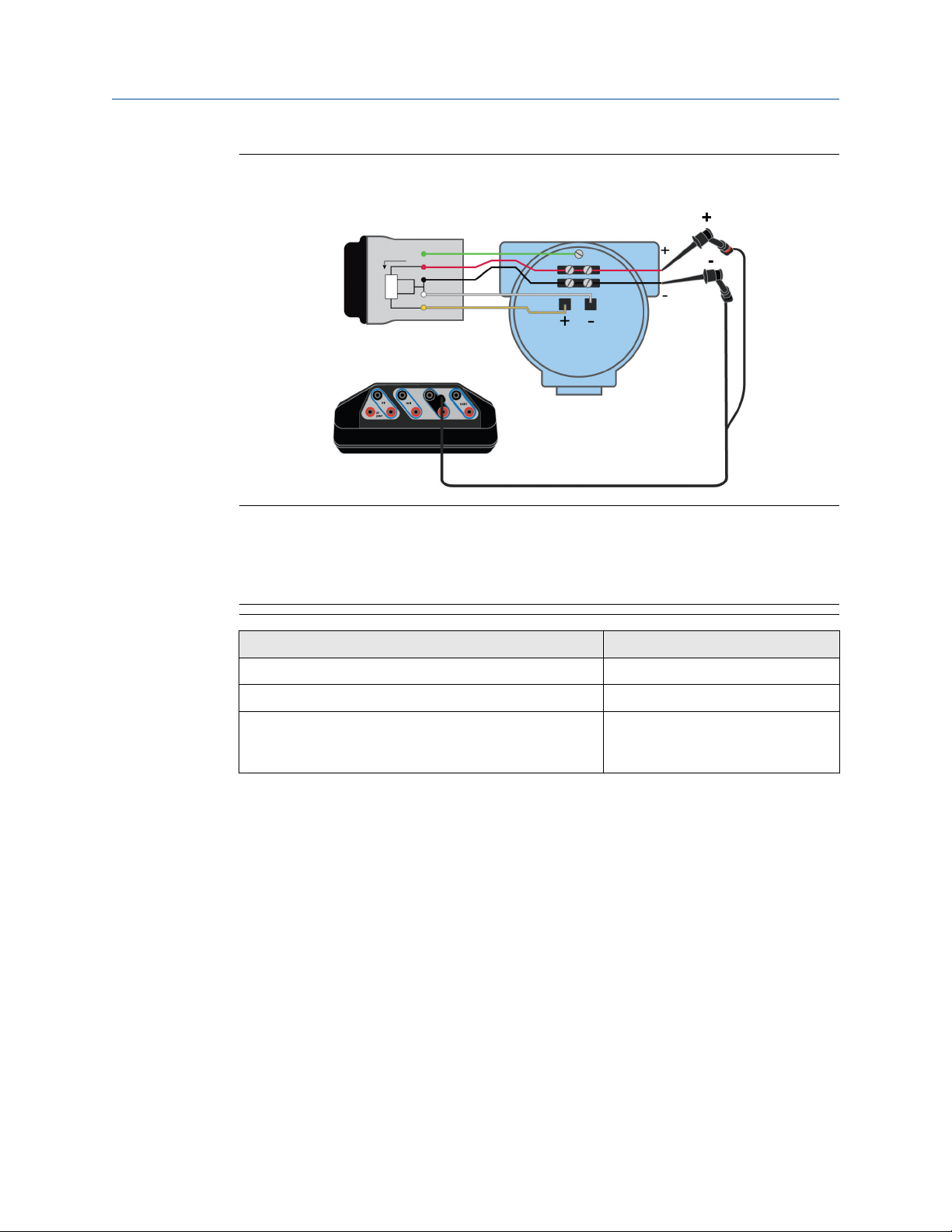
User Guide Field Communicator application
September 2021
Figure 3-19: Power and communicate with the THUM adapter attached to a HART
transmitter
Note
If you want to communicate with the THUM adapter rather than the device, ensure the
Auto-Connect option for the Field Communicator Settings is disabled. This allows the Field
Communicator application to detect both the THUM adapter and the transmitter, and let
you select which one to communicate with.
Device connection wizard prompts
Do you intend to provide power from the Trex unit?
Are you providing power to a transmitter or positioner?
Change Polling Option? Tap Yes and select the address for the
Answer
Yes
Transmitter
THUM adapter, the device, or "0,63"
for both.
User Guide 77

Field Communicator application User Guide
September 2021
Figure 3-20: Communicate with the THUM adapter attached to a powered HART
transmitter
Connect the lead set to the yellow and white wires.
Note
If you want to communicate with the THUM adapter, ensure the Auto-Connect option for
the Field Communicator Settings is disabled. This allows the Field Communicator
application to detect both the THUM adapter and the transmitter, and let you select which
one to communicate with.
A. Optional connection if the yellow and white wires are inaccessible.
B. Voltage source.
Device connection wizard prompts
Do you intend to provide power from the Trex unit?
Leads are attached to:
Change Polling Option? Tap Yes and select the address for the
Answer
No
Transmitter
THUM adapter, the device, or "0,63"
for both.
78 User Guide
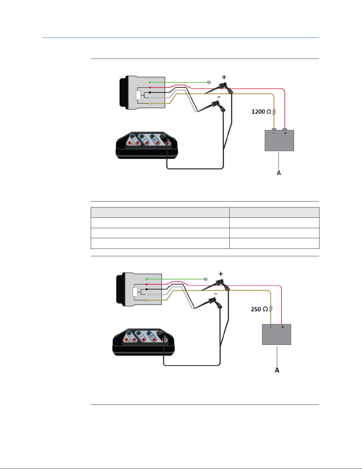
User Guide Field Communicator application
September 2021
Figure 3-21: Communicate with the THUM adapter powered by a voltage source
Connect the lead set to the yellow and white/black wires.
A. Voltage source.
Device connection wizard prompts Answer
Do you intend to provide power from the Trex unit?
Leads are attached to:
Change Polling Option? Tap Yes and select 63.
No
Transmitter
Figure 3-22: Communicate with the THUM adapter powered by a current source
Connect the lead set to the yellow and white/black wires. The 250 Ohm resistor is not
required, but it may be used to verify current.
A. Current source.
User Guide 79

Field Communicator application User Guide
September 2021
Device connection wizard prompts Answer
Do you intend to provide power from the Trex unit?
Leads are attached to:
Change Polling Option? Tap Yes and select 63.
No
Positioner
3.10.4 HART Device List
The Device List displays the devices that the Trex unit has detected. Each device is listed by
its tag and address. The Device List will not display when the Auto-Connect option for the
Field Communicator application is enabled and a device was found at address zero.
Tap a device displayed on the Device List to connect to it.
If a device is not listed, tap My Device Not Found to change the HART polling options.
Figure 3-23: HART Device List
80 User Guide
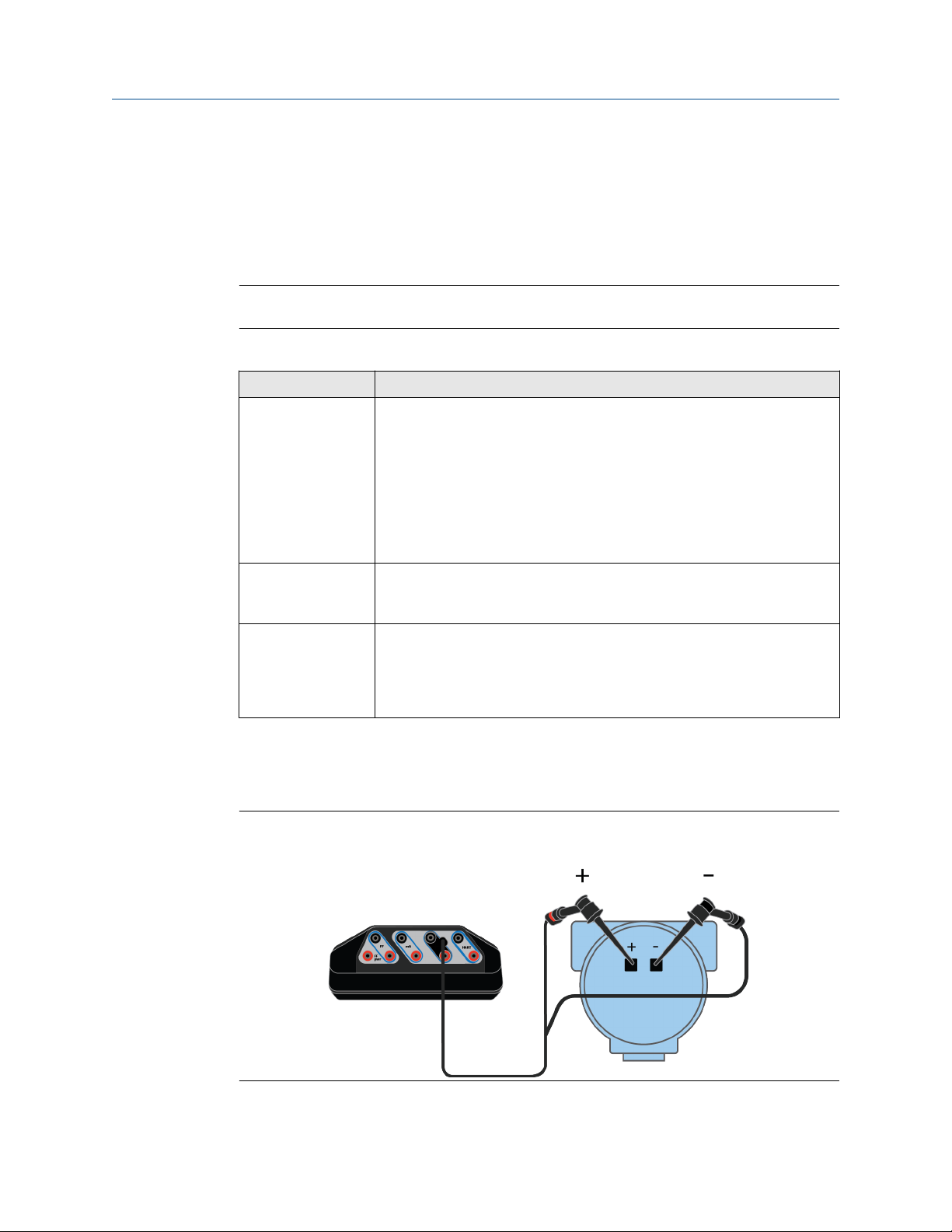
User Guide Field Communicator application
September 2021
3.11 Internal resistors
The Trex unit has internal resistors that can be used when the Trex unit powers a HART
transmitter, or when the HART transmitter is on a 4-20 mA current loop without a resistor.
The resistors are enabled through the device connection wizard in the Field
Communicator application.
Note
For positioners, the internal resistors in the Trex unit are disabled.
Available resistors
Resistor Use
167 Ohm Used when the Trex unit powers a HART transmitter. This is the only resistor
that is available when the Trex unit powers a transmitter.
The 167 Ohm resistor is available due to Intrinsic Safety limitations when
the Trex unit powers a device. If the current is high (for example 22.5 mA),
the voltage drops to a level that may not be enough to power the device.
The use of the lower valued resistor can reduce the amount of the voltage
drop. The HART signal is lower, but the shout/deaf mode helps increase the
HART signal amplitude for devices that do not meet the HART
specifications.
250 Ohm Used when you select to increase loop resistance in the device connection
wizard when connecting to a device on an externally-powered 4-20 mA
current loop.
500 Ohm Used when the Trex unit detects the current is too high for the 250 Ohm
resistor on an externally-powered 4-20 mA current loop. If the current
continues to be too high after adding this resistor, the Trex unit displays an
error message indicating the detected current exceeds the capacity of the
resistor. The 500 Ohm resistor is used for externally-powered current loops.
Connection to a transmitter powered by the Trex unit
To enable the 167 Ohm resistor, the Trex unit must be connected to the device using the
HART + pwr terminals.
Figure 3-24: Connection for using the Trex internal resistor when the Trex unit
powers the transmitter
User Guide 81
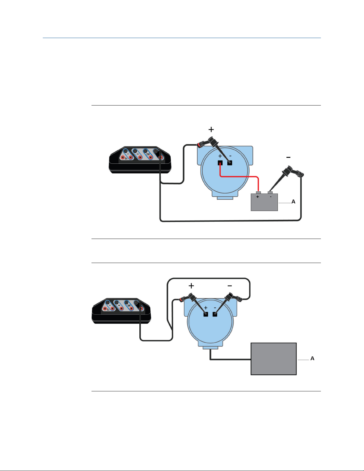
Field Communicator application User Guide
September 2021
Connections to externally-powered transmitters
To enable the internal resistors, the Trex unit must be connected to the device/loop in a
specific way.
For externally-powered 2-wire HART devices, the Trex unit must be connected in series. In
the diagram below, the Trex internal resistor is enabled in the HART terminals.
Figure 3-25: Connection for using the Trex internal resistor for an externally-powered
2-wire transmitter
A. Voltage source
For 4-wire transmitters, the Trex unit must be connected in parallel. In the diagram below,
the Trex internal resistor is enabled in the HART terminals.
Figure 3-26: Connection for using the internal resistor for a 4-wire transmitter
A. Voltage source
82 User Guide

User Guide Field Communicator application
September 2021
3.11.1 Enable or disable the internal resistors
If the Trex unit is powers the transmitter, there is no prompt/option to enable or disable
the internal 167 Ohm resistor. The Trex unit automatically applies the resistor when you
enable power to a transmitter from the device connection wizard.
If the Trex unit is connected to an externally-powered HART transmitter, the device
connection wizard prompts you if you want to increase loop resistance. The Trex unit then
selects the 250 Ohm or 500 Ohm resistor; you cannot select a specific value. The selected
resistor value is not displayed on the screen.
Procedure
1. If you want the Trex unit to power a 2-wire HART transmitter, do the following:
a) Connect the lead set to the HART + pwr terminals on the Trex unit and to the
communication terminals on the device.
Figure 3-27: Connection for providing power to a 2-wire HART
transmitter
b) In the Field Communicator application, tap HART.
c) Tap Yes when asked if you intend to provide power.
d) Tap Transmitter. The Trex unit applies the internal resistor.
e) Follow any additional prompts to connect to the device.
2. If the Trex unit is connected to an externally-powered 2-wire HART transmitter, do
the following:
a) Connect the lead set to the HART terminals on the Trex unit and to the
communication terminals on the device in-series. (If you are connecting to a
4-wire transmitter, connect the Trex unit in parallel.)
User Guide 83

Field Communicator application User Guide
September 2021
Figure 3-28: Connection for an externally-powered 2-wire transmitter
A. Voltage source
b) Tap HART.
c) Tap No when asked if you intend to provide power.
d) Tap Transmitter.
e) Tap No when asked if you want to change polling. (This assumes the device is
at address zero.)
f) Tap Yes when asked if you want to increase loop resistance.
g) Tap Next.
A message is displayed to indicate the internal resistor is being enabled.
3. To disable the internal resistor, disconnect the device from the Trex unit, or close
the Field Communicator application.
3.12 Power and connect to a HART device
The Trex unit can provide up to 16 volts (at 22.5 mA) to power a HART device. The Trex
unit must have the Device Communicator Plus communication module to power a HART
device (transmitter or positioner).
You do not need to add an external resistor. The Trex unit has a 167 Ohm internal resistor
in the HART + pwr terminals that is used when the Trex unit powers the transmitter.
If you try to apply power from the Trex unit when the device is externally-powered, the
Field Communicator application prevents the Trex unit from supplying power. This
protects the Trex unit from damage.
84 User Guide

User Guide Field Communicator application
September 2021
CAUTION
• The Trex unit cannot power a 4-wire device. Do not connect Trex unit to the power
terminals of a 4-wire device. This can blow a fuse inside the Trex unit. The repair/
replacement will need to be completed at an authorized service center.
• Remove the USB cable from the Trex unit before connecting to a device.
• Do not use the Trex unit to power a WirelessHART device. Providing power to a
WirelessHART device may damage the device.
WARNING
Do not add any external power to the device when the Trex unit is powering the device.
This can blow a fuse inside the Trex unit. The repair/replacement will need to be
completed at an authorized service center. Ensure the device is disconnected from the
loop/segment and no other wires are connected to the device before providing power
from the Trex unit.
Procedure
1. Connect the lead set to the HART + pwr terminals on the Trex unit and to the
communication terminals on the device.
Figure 3-29: Power a HART transmitter
User Guide 85

Field Communicator application User Guide
September 2021
Figure 3-30: Power a HART positioner
2. In the Field Communicator application, tap HART.
3. Tap Yes when prompted if you want the Trex unit to power the device.
4. Tap Transmitter or Positioner.
If you selected Positioner, the Trex unit provides power and 4 mA.
5. Follow any additional prompts.
You may see additional prompts if the Trex unit cannot connect to the device. For
example, you may be prompted to review the polling address. For a positioner, you
may be asked to increase current (mA) to increase the value from the original 4 mA.
The Online menu or the device dashboard displays, depending on the device type.
3.12.1
Related information
Wiring diagrams for HART devices and the Field Communicator application
Wiring diagrams for the Smart Wireless THUM™ Adapter and the Field Communicator
application
Disconnect a device
HART communication terminals
Internal resistors
Power and connect to a Smart Wireless THUM adapter
The Trex unit must have the Device Communicator Plus communication module to power
a THUM adapter.
When performing a bench configuration, the THUM adapter should be attached to a
device. However, the Trex unit can power a THUM adapter when it is not connected to a
HART device.
To connect to a device that has a THUM adapter attached, see Connect to an externally-
powered HART device or Power and connect to a HART device.
CAUTION
Remove the USB cable from the Trex unit before connecting to a device.
86 User Guide

User Guide Field Communicator application
September 2021
Procedure
1. Connect the lead set to the HART + pwr terminals on the Trex unit and the red/black
wires on the THUM adapter.
Figure 3-31: THUM adapter wiring with 250 Ohm resistor
2. In the Field Communicator application, tap HART.
3. Tap Yes when prompted if you want the Trex unit to power the device.
4. Tap Positioner.
5. When prompted, change the polling address to 63.
6. Follow any additional prompts to connect to the THUM adapter.
The device menu is displayed.
Related information
HART communication terminals
Wiring diagrams for the Smart Wireless THUM™ Adapter and the Field Communicator
application
Disconnect a device
3.13 Connect to an externally-powered HART device
By default, the Trex unit tries to automatically connect to the device at address zero. See
Automatically connect to a HART device for more information.
CAUTION
Remove the USB cable from the Trex unit before connecting to a device.
Note
The Trex unit acts as a secondary HART master on a HART loop.
Procedure
1. Connect the lead set to the HART terminals on the Trex unit and to the
communication terminals on the device. See the HART wiring diagrams topic for
the connection details.
If you want to use the Trex internal resistor, connect the Trex unit is series with the
device.
User Guide 87

Field Communicator application User Guide
September 2021
2. Open the Field Communicator application.
The Trex unit may automatically detect or connect to the device.
3. If the Trex unit does not automatically connect to the device, tap HART and do the
following:
a) Tap No when asked if you want to provide power from the Trex unit.
b) Select Transmitter or Positioner.
c) Follow any additional prompts.
You may see additional prompts if the Trex unit cannot connect to the
device. For example, you may be prompted to review the polling address if
the device is not at address zero, or to increase loop resistance. The Online
menu or the device dashboard displays, depending on the device type.
d) Tap the device displayed on the Device List.
4. To disconnect a device, tap Menu → Disconnect, or remove the lead set.
Related information
Wiring diagrams for HART devices and the Field Communicator application
Wiring diagrams for the Smart Wireless THUM™ Adapter and the Field Communicator
application
Disconnect a device
HART communication terminals
Internal resistors
3.14 Online HART devices
3.14.1 HART icons
When the Trex unit communicates with a HART device, one of the following icons appears
in the status bar at the top of the screen. The icon shows the status of the communication.
Icon
Related information
Status bar
Description
The Trex unit is communicating with a live, online HART device.
The Trex unit is communicating with a HART loop with a device in burst
mode. Burst mode is a communication mode in a HART transmitter to send
data at regular intervals.
The Trex unit is running in shout/deaf mode, which helps it communicate
with a device when it is on a noisy HART loop.
The Trex unit is running in shout/deaf mode and communicating to a HART
loop with a device in burst mode.
88 User Guide

User Guide Field Communicator application
September 2021
3.14.2 Device Setup options
The Device Setup menu accesses every configurable parameter for the connected device.
Some devices may not display a Device Setup menu or it may display different options.
The list below is a general overview of the options. See the device documentation for more
information.
Tap Device Setup to view the process variables, diagnostics and service, basic setup,
detailed setup, and review menus.
Process Variables
The Process Variables menu lists all process variables and their values. Process variables
are continuously updated.
Diagnostics and Service
Option Description
Diagnostics and Service Run device and loop tests as well as calibration options. The
diagnostics and service operations that are available vary widely from
device to device and are defined in the device description.
Test device View the status as well as self and master test of the device. Test
device initiates a diagnostic routine at the device and can report an
electronics failure, as well as other failures that can affect
performance.
Loop test Set the output of the device at a specified analog value, and test the
integrity of the loop and the operation of indicators, recorders, or
similar devices in the loop.
Calibration Perform such operations a sensor trim, D/A trim, and scaled D/A trim.
Basic Setup
The options in the Basic setup menu are the most fundamental tasks that can be
performed with a device. These tasks are a subset of the options available under the
Detailed setup menu.
Option
Tag Modify the tag for the device.
Unit Select the engineering units that are displayed.
Damping Change the response time of the transmitter. It is often used to
Range values Modify the analog output scaling.
Description
smooth the output when there are rapid input variations.
Detailed Setup
The Detailed setup menu provides access to every editable device parameter and all
device functions. The Detailed setup menu varies from one HART device to another.
Functions in this menu can include tasks such as characterization, configuration, and
sensor and output trims.
User Guide 89
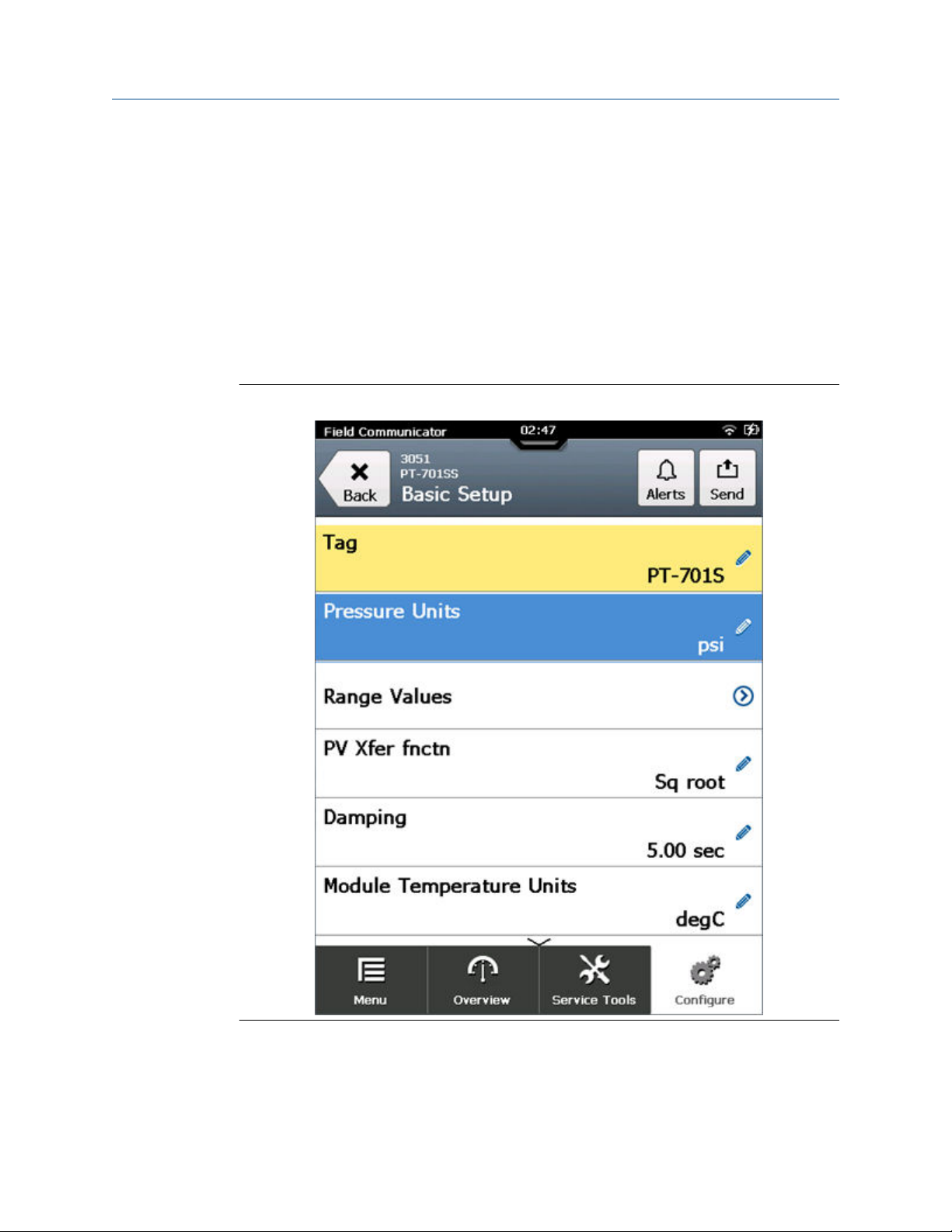
Field Communicator application User Guide
September 2021
Review
The Review menu lists all the static parameters read from the connected device, including
information about the device and sensor setup and limitations. It may also include
information about the connected device such as tag, materials of construction, and device
software revision.
3.14.3 Changing device parameters
When you change a parameter for a device, the Field Communicator application highlights
the changed parameter yellow until you send the change to the device. You can send one
or more changes to a device.
Figure 3-32: Changed parameter is highlighted yellow
3.14.4
90 User Guide
Change a HART device parameter
You can modify one or more parameters and then send the changes to the device.

User Guide Field Communicator application
September 2021
Procedure
1. Connect to the HART device.
2. Go to the parameter you want to change.
See the device documentation for more information. Each device has different
menus.
3. Make the desired change.
The changed parameter is highlighted yellow.
4. Tap OK.
5. Tap the Send icon in the upper right corner.
A list of all the changes you made is displayed.
6. Review the change.
Tap Discard to undo the change and close the screen. Tap Cancel to keep the
change and send it to the device at a later time.
7. Tap Send.
The change is sent to the device. The yellow highlight is removed from the changed
parameters.
3.14.5
Edit a HART configuration
Prerequisites
Note
Do not edit a configuration on the Trex unit while you are connected to the Configuration
Management PC application.
Procedure
1. In the Field Communicator application, tap HART Offline.
2. Tap Offline Config → Edit Existing.
3. Tap the column heading to sort configurations by File Name or Tag. Select the
configuration you want to edit, and tap OK.
4. Select and edit the parameters.
5. Tap the checkbox to mark the parameter for writing.
Note
Unmarked parameters are saved but not sent when you transfer the configuration
to a connected device.
6. Tap Save when you finish editing the parameters.
7. If necessary, enter a new configuration name.
8. Tap OK.
3.14.6
User Guide 91
Display the HART short tag or long tag
You can select the HART short or long tag to display for HART revision 6 or higher devices.
By default, HART revision 7 devices display the long tag. The option will not display for
earlier devices.

Field Communicator application User Guide
September 2021
Note
The selected tag is not retained the next time you connect to the device. You need to
select the desired tag each time you connect the device.
If you want to change the value of the HART tag, see the device documentation for more
information. The location of these tag parameters varies because it is determined by the
device manufacturer.
Procedure
1. Connect to the HART device.
2. Tap the tag that is displayed on the top of the screen.
Figure 3-33: Tap the device tag
3. Select Tag or Long Tag.
The displayed tag changes.
92 User Guide

User Guide Field Communicator application
September 2021
3.14.7 View device alerts
Procedure
1. Connect to a HART device.
2. If the device has alerts, tap Alerts at the top of the screen.
The list of alerts is displayed.
Figure 3-34: Alerts button
3.14.8
3.14.9
3. Tap OK.
Send a configuration to a connected HART device
Prerequisites
You must have at least one configuration saved in the Trex unit for the connected device
type.
Procedure
1. Connect to the HART device.
2. Tap the Menu tab in the application bar.
3. Tap Send Config.
4. Select a saved configuration, and tap OK.
5. Review the parameters, and tap Send.
Save a configuration from a HART device
You can save a copy of the configuration from the connected device. The configuration
has only non-dynamic parameters.
Procedure
1. Connect to the HART device.
2. Tap the Menu tab.
3. Tap Save Config.
4. Enter a filename for the configuration, and tap OK.
The configuration is saved in the Trex unit.
User Guide 93

Field Communicator application User Guide
September 2021
3.15 Offline HART configurations
The Trex unit lets you work with HART configurations. You can create, edit, copy, delete,
and rename configurations.
If you are not connected to a HART device, an Offline Config button displays on the main
Field Communicator menu. You can edit and store a configuration on the Trex unit.
If you are connected to a HART device, you can either Save Config to the Trex unit, or Send
Config to the connected device.
You can also back up the configurations to a PC by using the Configuration Management
application. For more information, see the Help included with the Configuration
Management application.
Note
Do not edit a configuration on the Trex unit while you are connected to the Configuration
Management PC application.
3.15.1
Create a HART configuration
Create a new configuration for a specific device type and revision. You can then apply this
configuration to multiple devices.
Procedure
1. In the Field Communicator application, tap HART Offline.
2. Tap Offline Config → New.
3. Tap a manufacturer.
4. Tap a device type.
5. Tap a device revision.
6. Tap OK.
7. Select and edit the necessary parameters.
8. Tap OK to mark the parameter for writing.
Note
Unmarked parameters are saved but not sent when you transfer the configuration
to a connected device.
9. Tap Save when you finish editing the parameters.
10. Enter a name for the configuration, and tap OK.
The configuration file is saved.
3.15.2
94 User Guide
Edit a HART configuration
Prerequisites
Note
Do not edit a configuration on the Trex unit while you are connected to the Configuration
Management PC application.

User Guide Field Communicator application
September 2021
Procedure
1. In the Field Communicator application, tap HART Offline.
2. Tap Offline Config → Edit Existing.
3. Tap the column heading to sort configurations by File Name or Tag. Select the
configuration you want to edit, and tap OK.
4. Select and edit the parameters.
5. Tap the checkbox to mark the parameter for writing.
Note
Unmarked parameters are saved but not sent when you transfer the configuration
to a connected device.
6. Tap Save when you finish editing the parameters.
7. If necessary, enter a new configuration name.
8. Tap OK.
3.15.3
3.15.4
Copy a HART configuration
You can create a copy of a saved configuration.
Procedure
1. In the Field Communicator application, tap HART Offline.
2. Tap Offline Config → Copy.
3. Select the configuration you want to copy, and tap OK.
4. Enter a name for the new copy of the configuration, and tap OK.
5. Tap OK when asked if you want to copy the file.
The configuration is copied and saved to the Trex unit.
Rename a HART configuration
Procedure
1. In the Field Communicator application, tap HART Offline.
2. Tap Offline Config → Rename.
3. Select the file to rename, and tap OK.
4. Enter a new name for the configuration, and tap OK.
5. Tap OK when asked if you want to rename the configuration.
The configuration is renamed.
3.15.5
User Guide 95
Delete a HART configuration
Procedure
1. In the Field Communicator application, tap HART Offline.
2. Tap Offline Config → Delete.

Field Communicator application User Guide
September 2021
3. Select the file to delete, and tap OK.
4. Tap OK when asked if you want to delete the file.
The file is deleted.
3.16 Favorites
You can add the most commonly used HART menu items to a list of favorites for quick
access. (This feature is similar to the favorites/bookmark feature in a web browser.) You
can add menus (with submenus), methods, or variables to the favorites. The list of
favorites is specific to a device revision. It does not include items added from multiple
types of devices.
If the device description for the device has predefined favorites, they are available from
the Favorites screen. Also, some devices may include additional menu items in the
favorites list.
3.16.1
3.16.2
Open a menu item from the favorites list
The Favorites option is supported for only HART devices.
Procedure
1. Connect to a HART device.
2. Tap Menu → Favorites.
The Trex unit displays the list of favorites for the device.
3. Tap a saved favorite to open that menu item.
Add a menu item to the favorites list
Add a menu item for a HART device to the favorites for quick access.
Procedure
1. Connect to a HART device.
2. Go to the menu item you want to add to the favorites.
3. Press the menu item for 2 seconds.
A menu appears.
96 User Guide

User Guide Field Communicator application
September 2021
Figure 3-35: Favorites menu
4. Tap Add To Favorites.
The menu item is added to the favorites.
5. To verify the option was added, go to Menu → Favorites.
3.16.3
User Guide 97
Remove a menu item from the favorites list
Note
Some devices have default options, such as tag or range values, already in the favorites
list. You cannot remove these default options. You can only remove options you added to
the favorites list.
Procedure
1. Connect to a HART device.
2. Tap Menu → Favorites.

Field Communicator application User Guide
September 2021
3. Press and hold a menu item displayed in the Favorites list.
4. Tap Remove From Favorites.
3.17 Polling options for HART devices
The Field Communicator application uses the HART polling options to search for
connected devices. By default, the Trex unit searches for a device at address zero and
automatically connects to the device, if it is detected. Most HART device installations
contain one device per HART loop and the device address is zero. Multidrop mode is
enabled by changing the address from zero to any address between 1 and 63. See the
device documentation for more information about changing a device address.
If the Trex unit cannot find the device at address zero, the device connection wizard
displays a message asking if you want to change the polling option.
The Trex unit can poll by:
• Address - Select an address (0-63).
• Tag - Enter the tag of the device.
3.17.1
• Long Tag - Enter the long tag of the device.
Note
If the Trex unit polls addresses greater than 15 on a loop with HART Universal Revision 5
devices, those devices may appear at multiple addresses.
Note
If you have two devices on a HART loop and one device is at address zero, disable the AutoConnect option in the Trex Settings. Otherwise, the Trex unit automatically connects to
the device at address zero and does not detect the second device.
Set the polling options for HART devices
When you connect to a device, the Trex unit by default automatically polls address zero
and connects to the device at that address. If the Trex unit does not find a device at
address zero, you are prompted to change the polling address in the device connection
wizard.
If you change the polling option, the selected option is not saved. You need to select the
desired option each time you connect to a device.
Note
If you have two devices on a HART loop and one device is at address zero, disable the AutoConnect option in the Trex Settings. Otherwise, the Trex unit automatically connects to
the device at address zero and does not detect the second device.
Procedure
1. Connect the lead set to the Trex unit and to the device.
2. Open the Field Communicator application.
3. If the Trex unit does not automatically connect to the device, tap HART.
4. Follow the prompts to connect to the device.
98 User Guide

User Guide Field Communicator application
September 2021
5. Tap Yes when prompted if you want to change the polling option.
6. Select a polling option at the top of the screen.
Option Description
Address Poll for devices at the specified addresses.
• Address 0 : Poll non multi-dropped loops. This is the default option.
• Address Range 0 to 15 : Poll HART Universal Revision 5 or earlier
devices on multi-dropped loops.
• Address Range 0 to 63 : Poll HART Universal Revision 6 or newer
devices on multi-dropped loops.
• Address 63 (wireless adapter) : Poll the default address for
WirelessHART adapters.
• Address 0 and 63 (wireless adapter) : Poll address 0 and the
default address for WirelessHART adapters.
• Custom : Poll a unique or non-consecutive group of addresses
(example: “0, 5-7, 12”). Use a hyphen to specify consecutive
addresses and/or a comma to separate numbers or groups of
numbers.
Tag Poll by the tag of the device.
Long Tag Poll by the long tag of the device. (Only supported in HART Universal
Revision 6 or higher devices.)
3.18 Connections to FOUNDATION fieldbus devices
Connect the Trex unit to the device by using the lead set and the appropriate terminals. An
error message appears if the lead set is connected incorrectly. Digital communication is
susceptible to electrical noise; follow proper wiring instructions.
Note
Dynamic variables shown while online represent the digital data being sent from the
device.
3.18.1
Precautions for using the Trex unit with FOUNDATION fieldbus devices
WARNING
If a fieldbus segment is connected to a host system, the changes made with the Trex unit
may not be recorded in the host system’s permanent database. Verify the changes in the
database. Otherwise, this could cause unpredictable results and, depending upon your
application, process disruption leading to property damage, serious injury, or death.
Ensure all safety precautions and work procedures have been followed.
User Guide 99
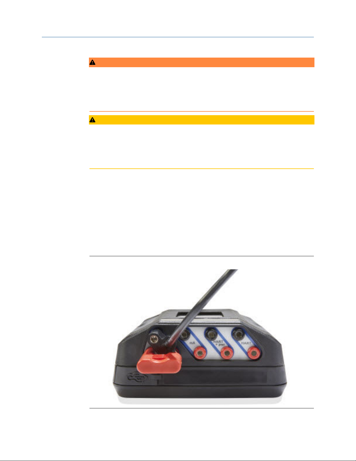
Field Communicator application User Guide
September 2021
WARNING
Changing device parameters could adversely affect the control of your process. Put the
control loop in Manual/Out of Service before applying changes. Verify the output before
returning the control loop to Auto. Failure to do so could result in property damage,
serious injury, or death. Ensure all safety precautions and work procedures have been
followed.
CAUTION
The Trex unit draws approximately 12 mA from the fieldbus segment when it is online.
(The Trex unit draws 0 mA when it is offline.) Ensure the power supply or barrier on the
fieldbus segment has the capacity to provide this additional current when the Trex unit is
online. If a heavily loaded fieldbus segment is drawing near the capacity of the segment’s
power supply, connecting the Trex unit may result in loss of communication.
3.18.2
FOUNDATION fieldbus communication terminals
The Trex unit has terminals that enable communication with FOUNDATION fieldbus
devices. Insert the lead set into the FF terminals and connect to a FOUNDATION fieldbus
device or to a connection point on the fieldbus segment.
On the Device Communicator Plus communication module, the red FF pwr terminal
enables the Trex unit to power one FOUNDATION fieldbus device. To use this terminal, you
need the FOUNDATION fieldbus Power Plug that connects to the FF pwr terminal and the
positive (red) FF terminal. This lets the Trex unit communicate with and power one
FOUNDATION fieldbus device.
Figure 3-36: FOUNDATION fieldbus Power Plug attached to the Trex unit
100 User Guide
 Loading...