

Page 1

8051 5.1 Compressor User Guide
AMS
NEVE
8051
5.1 Compressor
User Guide
527-357
Issue 2
© 2005 AMS Neve Ltd own the copyright of all
information and drawings contained in this manual which
are not to be copied or reproduced by any means or
disclosed in part or whole to any third party without
written permission.
As part of our policy of continual product improvement,
we reserve the right to alter specifications without notice
but with due regard to all current legislation.
Disclaimer: The information in this manual has been
carefully checked and is believed to be accurate at the
time of publication. However, no responsibility is taken by
us for inaccuracies, errors or omissions nor any liability
assumed for any loss or damage resulting either directly or
indirectly from use of the information contained within it.
Issue 2
AMS NEVE LTD • BILLINGTON ROAD • BURNLEY
TELEPHONE: +44 (0) 1282 457011 • FAX: +44 (0)1282 417282
TELEPHONE: +44 (0) 20 7916 2828 • FAX: +44 (0)20 79162827
HEAD OFFICE
LANCS BB11 5UB • ENGLAND
LONDON OFFICE
NORTH AMERICAN OFFICES
AMS NEVE INC., NEW YORK
TEL: +1 (212) 965 1400 • FAX: +1 (212)965 9306
AMS NEVE INC., HOLLYWOOD
TEL: +1 (818) 753 8789 • FAX: +1 (818)623 4839
e-mail: info@ams-neve.com
http://www.ams-neve.com
Page 2

8051 5.1 Compressor User Guide
Contents
Introduction 1
Dimensions 2
Rack Mounting and Cooling 2
Power Requirements 2
Mains Supply 2
Rear Panel Connectors 3
Compressor Controls 4
LFE Filter (Filter to Channel) 4
Bypass 5
Sidechain Link 6
Sidechain Filter 6
Control Link 7
SC Trims and Threshold 8
EXT Control 9
Threshold 10
Gain Makeup 10
Ratio 10
Attack 11
Recovery 11
Gain Reduction Meters 11
Key Input 12
Key Filter 12
Bias Control 12
Output Level 12
Power 12
Mastering Compressor Controls (AM5292) 13
8051 Compressor - 88R(S) Console mounted 14
I/O Wiring (AM5052 & AM5265) 15
Specifications 16
8051 Block Diagram 17
Issue 2 Page ii
Page 3
8051 5.1 Compressor User Guide
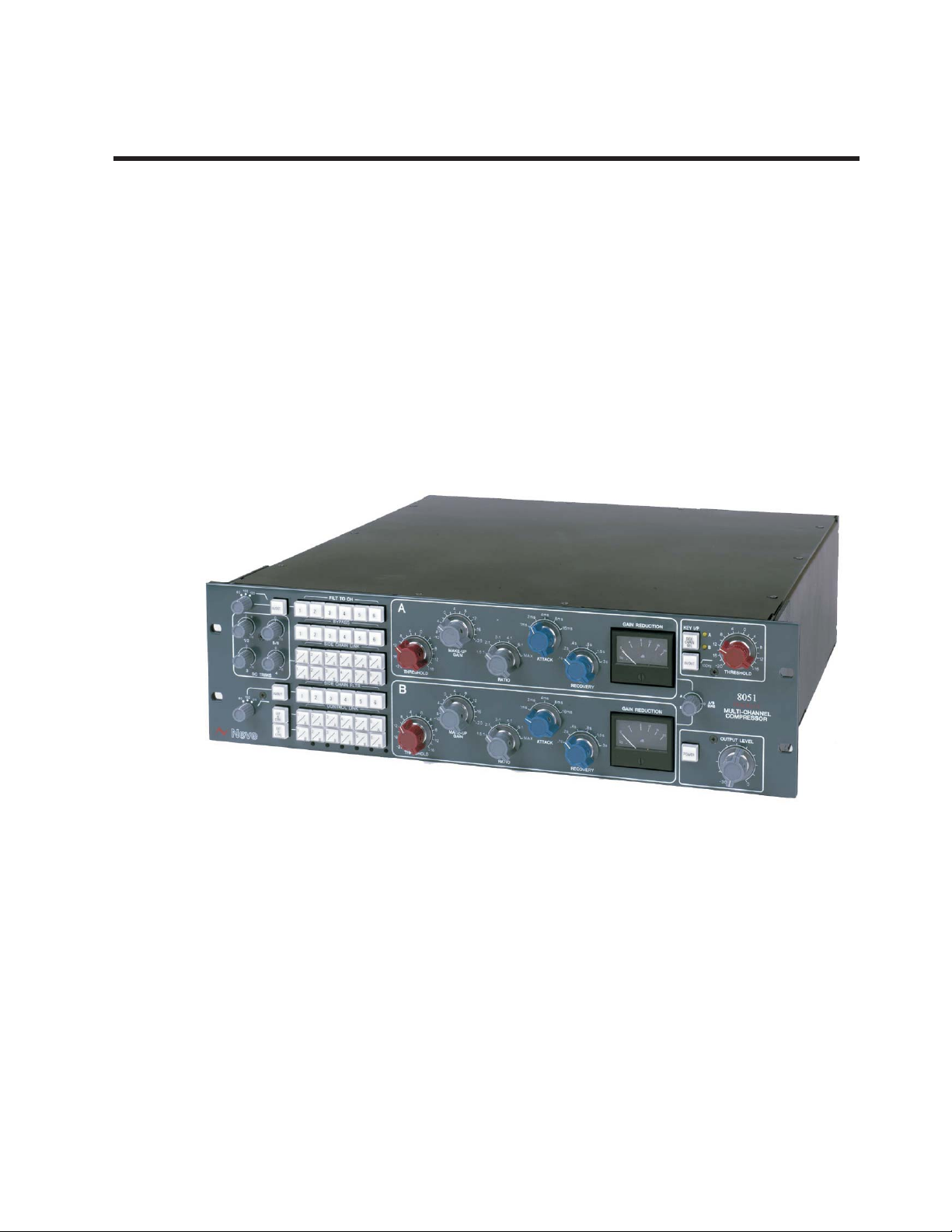
Introduction
The 8051 is an analogue compressor that provides six transformer balanced audio paths
complemented by two sidechains and a key input. Input and output to the sidechains is assignable
to and from the six channels. Assignable LFE filters on the input and sidechains along with the key
input provide integrated bass management.
Flexible sidechain routing, trimming and filtering make this a powerful and responsive tool for
surround mixing.
The 8051 uses the same feedback topology as the 33609 compressor and includes the same
transformers, diode-bridge gain control and discrete power amplifiers in the audio path.
8051 5.1 Compressor
Issue 2 Page 1
Page 4
8051 5.1 Compressor User Guide
Dimensions
Units U Depth
8051 Compressor
(AM4851 and AM5292)
not including mains plug
3 500 (20) 135 (5.25) 10.5 (23)
Rack Mounting and Cooling
The rack units should be installed in a 19" cabinet with access to the front and rear.
No specific air conditioning is required for the racks, provided that there is a free flow of air through
the rack from front to back, and that the ambient air is maintained below 30 degrees centigrade.
Therefore the racks may be stacked.
Power Requirements
8051 Units
Rated Voltage 100-250V AC
Rated Frequency 47-63 Hz
Rated Current .25A at 250V
mm (inches)
Height
mm (inches)
Approx. Weight
kg (lbs)
Mains Supply
The power supply unit is a universal input type therefore no mains operating voltage setting is
required.
The CH (chassis) and 0V are linked externally.
See the rear panel layout for AM4851 & AM5292.
Primary Protection Fuse:
Operating Voltage 250/110V
Fuse Rating and Type T1.6A/T1.6A A/S Ceramic
Location Rear Panel IEC Mains Connector
Issue 2 Page 2
Page 5
8051 5.1 Compressor User Guide
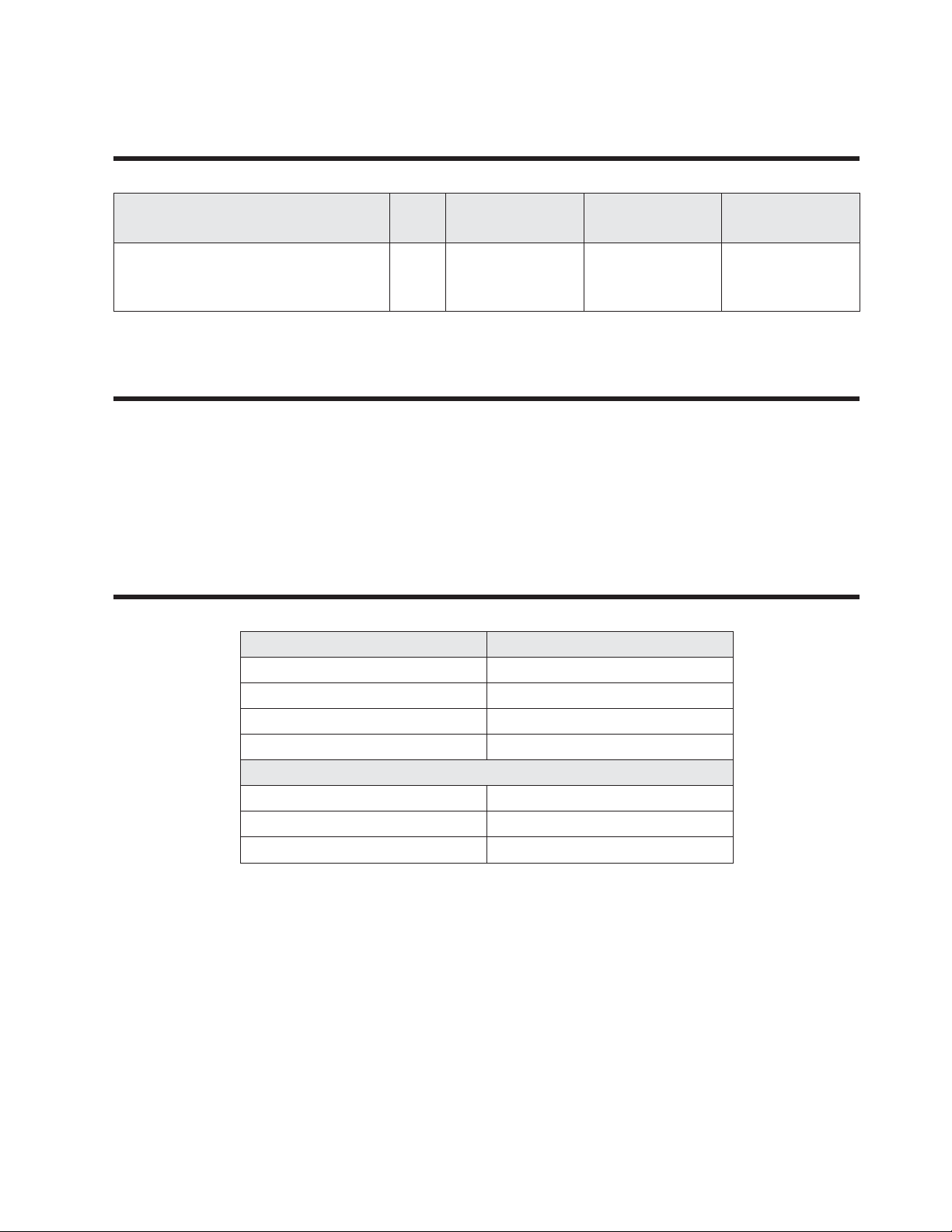
Rear Panel Connectors
Mating connectors are not supplied with these units.
-
CONTROL
VOLTAGE I/O
WARNING
DISCONNECT MAINSLEAD
TO ISOLATEUNIT.
NO USERSERVICEABLE
PARTSINSIDE
HAZARDOUS VOLTAGES INSIDE
REFER TOMANUALS
CHASSIS INTERNAL
0V
PLEASE SEE
MANUAL
FUSE 1.6AA/S CERAMIC
INPUT VOLTAGE 100-250V AC
INPUT FREQUENCY47-63Hz
INPUT 2INPUT 3INPUT 4INPUT 5INPUT 6KEY INPUT
INPUT 1
OUTPUT 1OUTPUT 2OUTPUT 3OUTPUT 4OUTPUT 5OUTPUT 6
PUSHPUSHPUSHPUSHPUSHPUSHPUSH
CONTROL VOLTAGE I/O - 15 Pin D-Type
KEY INPUT - XLR Socket
INPUT 1-6 - XLR Socket
OUTPUT 1-6 - XLR Plug
-
These connectors apply to both the Standard and Mastering Compressor (AM4851 &
AM5292).
-
For I/O wiring on 88R(S) console mounted compressors (AM5052 &AM5265) see page 15 .
Issue 2 Page 3
Page 6
8051 5.1 Compressor User Guide
0-5.5
0
8
dB
4
0
12
16
20
8
dB
4
0
12
16
20
A
B
-10
-10
+20
+20
2ms
2ms
4ms
4ms
6ms
6ms
8ms
8ms
16ms
16ms
-20
-20
-20
+16
+16
+16
1.5:1
1.5:1
2:1
2:1
8
8
8
8
8
8
8
8
8
8
12
12
12
12
12
12
12
12
16
16
16
16
16
4
4
4
4
4
4
4
4
4
4
0
0
0
0
0
3:1
3:1
4:1
4:1
6:1
6:1
max
max
.1s
.1s
.2s
.2s
.4s
.4s
.8s
.8s
1.5s
1.5s
3s
3s
DISCRETE
Neve
+16
8
8
12
4
4
0
DISCRETE
8
dB
4
0
12
16
20
4ms
6ms
8ms
16ms
-20
+16
8
8
12
12
16
4
4
0
..2s
.4s
.8s
1.5s
0
8
dB
4
0
12
16
20
8
dB
4
0
12
16
20
4ms
4ms
6ms
6ms
8ms
8ms
16ms
16ms
-20
+16
8
8
12
12
16
4
4
0
max
.1s
.2s
..2s
.4s
.4s
.8s
.8s
1.5s
1.5s
3s
DISCRETE
8
dB
4
0
12
16
20
16ms
-20
+16
8
8
12
12
16
4
4
0
.4s
.8s
1..5s
3s
0
8
dB
4
0
12
16
20
8
dB
4
0
12
16
20
16ms
16ms
-20
+16
8
8
12
12
16
4
4
0
.4s
.4s
.8s
.8s
1.5s
1..5s
3s
3s
DISCRETE
8
dB
4
0
12
16
20
2ms
4ms
6ms
8ms
16ms
-20
+16
8
8
12
12
16
4
4
0
3:1
4:1
6::1
max
.1s
.2s
.4s
.8s
1.5s
3s
0
8
dB
4
0
12
16
20
8
dB
4
0
12
16
20
2ms
2ms
4ms
4ms
6ms
6ms
8ms
8ms
16ms
16ms
-20
+16
8
8
12
12
16
4
4
0
3:1
3:1
4:1
4:1
6:1
6::1
max
max
.1s
.1s
.2s
.2s
.4s
.4s
.8s
.8s
1.5s
1.5s
3s
3s
DISCRETE
8
dB
4
0
12
16
20
+20
2ms
4ms
6ms
8ms
16ms
-20
+16
2:1
8
8
8
112
12
12
16
16
4
4
4
0
0
3:1
4:1
6:1
.2s
.4s
.8s
1.5s
0
8
dB
4
0
12
16
20
8
dB
4
0
12
16
20
+20
+20
2ms
2ms
4ms
4ms
6ms
6ms
8ms
8ms
16ms
16ms
-20
+16
1.5:1
2:1
2:1
8
8
8
8
8
12
112
12
12
12
16
16
16
4
4
4
4
0
0
0
3:1
3:1
4:1
4:1
6:1
6:1
max
.1s
.2s
.2s
.4s
.4s
.8s
.8s
1.5s
1.5s
3s
DISCRETE
8
dB
4
0
12
16
20
-10
+20
2ms
4ms
6ms
8ms
16ms
-20
+116
+16
1.5:1
2:1
8
8
8
8
8
8
12
12
12
12
16
16
4
4
4
4
4
4
0
0
0
3:1
4:1
6:1
max
.1s
.2s
.4s
.8s
1.5s
3s
0
8
dB
4
0
12
16
20
8
dB
4
0
12
16
20
-10
-10
+20
+20
2ms
2ms
4ms
4ms
6ms
6ms
8ms
8ms
16ms
16ms
-20
+16
+116
+16
1.5:1
1.5:1
2:1
2:1
8
8
8
8
8
8
8
8
8
8
12
12
12
12
12
12
16
16
16
4
4
4
4
4
4
4
4
4
4
0
0
0
0
0
3:1
3:1
4:1
4:1
6:1
6:1
max
max
.1s
.1s
.2s
.2s
.4s
.4s
.8s
.8s
1.5s
1.5s
3s
3s
DISCRETE
+116
8
8
12
4
4
0
Neve
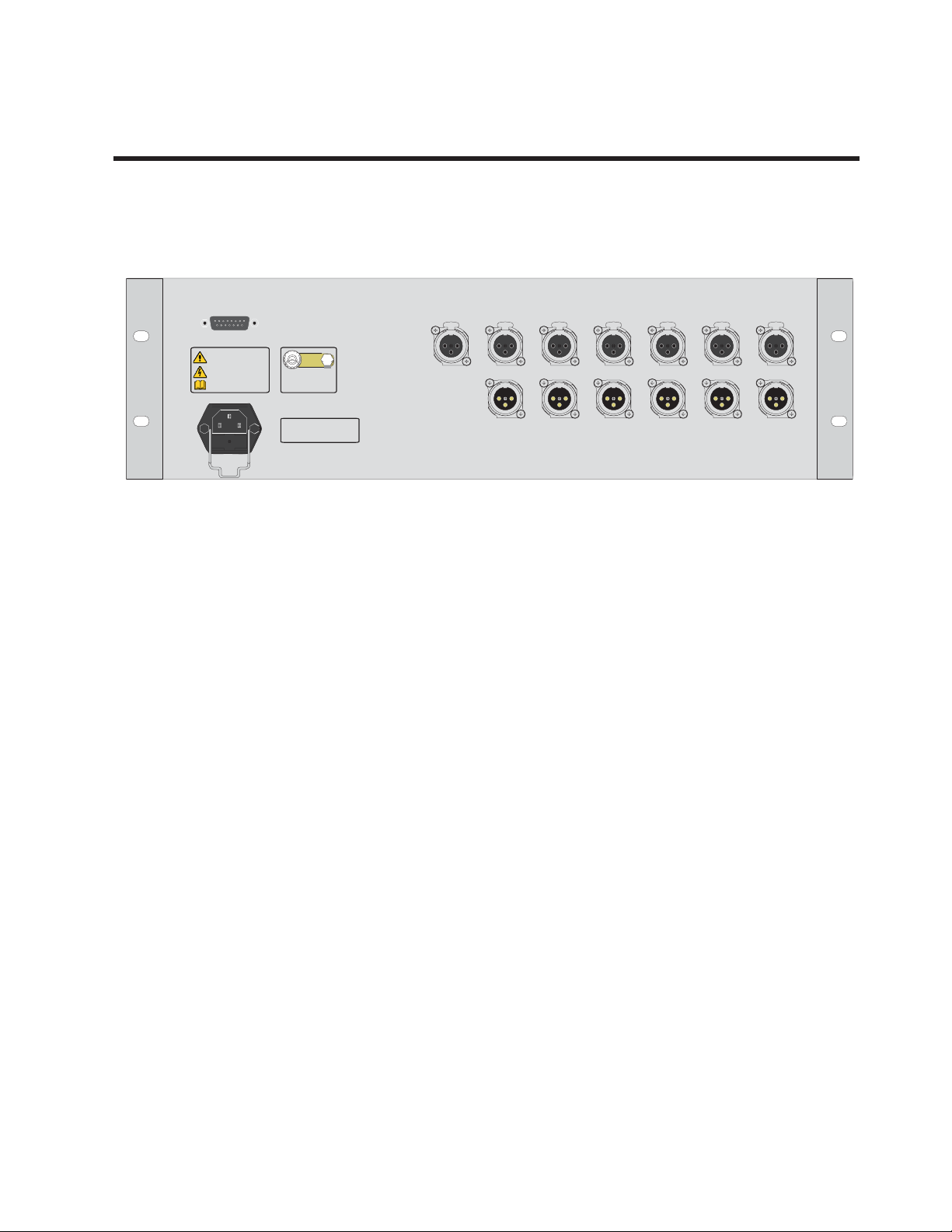
Compressor Controls
100
120
Hz
Hz
15
15
0
1/2
0
3
SC TRIMS dB
100
IN/OUT
0
15
15
15
5/6
0
15
15
15
4
IN/OUT
1208080
EXT
A
CTRL
EXT
B
CTRL
FILTER TO CHANNEL
5
3
1
2
4
BYPASS
1
2
MST
M
SIDECHAIN LINK
123456
A
A
123456
B
B
SIDECHAIN FILTER
1
2
123456
A
A
123456
B
B
3
A
B
3
CONTROL LINK
A
B
5
4
A
B
5
4
A
B
6
6
A
A
B
B
6
A
A
B
B
LFE Filter (Filter to Channel)
A 12dB/octave low-pass filter can be assigned to
any one channel. This filter is applied directly to the
input before the relay-bypass point, and its -3dB
frequency is selectable from 80, 100 or 120Hz.
A
4
8
12
16
-20
THRESHOLD dBu
B
4
8
12
16
-20
THRESHOLD dBu
RATIO
RATIO
6ms
4ms
8ms
2ms
4:1
6:1
2ms
4:1
6:1
16ms
.4s
.2s
ATTAC K
.1s
max
RECOVERY
6ms
4ms
8ms
16ms
.4s
.2s
ATTAC K
.1s
max
GAIN REDUCTION
.8s
1.5s
dB
3s
8
12
4
0
GAIN REDUCTION
8
12
4
0
.8s
1.5s
dB
3s
KEY I/P
SIDE
CHAIN
16
SEL
20
IN/OUT
A
B
16
20
POWER
RECOVERY
100
120
80
Hz
15
15
80
Hz
0
1/2
0
3
SC TRIMS dB
100
IN/OUT
1
0
1
MST
15
15
15
15
120
M
15
5/6
0
123456
123456
15
4
IN/OUT
1
EXT
123456
A
CTRL
EXT
123456
B
CTRL
A
B
100Hz
A/B
0
BIAS
2
2
A
B
2
A
B
4
0
8
12
16
-20
THRESHOLD dBu
8051
DISCRETE
MULTI-CHANNEL
COMPRESSOR
OUTPUT LEVEL dB
FILTER TO CHANNEL
3
4
BYPASS
3
4
SIDECHAIN LINK
A
A
B
B
SIDECHAIN FILTER
3
4
CONTROL LINK
A
A
B
B
4
8
12
+16
0-5.5
5
6
5
6
A
A
A
B
B
B
5
6
A
A
A
B
B
B
4
8
0
12
4
8
0
-10
4
+16
4
8
0
-10
4
+16
8
12
8
12
0
MAKE-UP
GAIN dB
4
MAKE-UP
GAIN dB
16
3:1
+20
2:1
1.5:1
8
12
16
3:1
+20
2:1
1.5:1
Issue 2 Page 4
Page 7

8051 5.1 Compressor User Guide
Neve
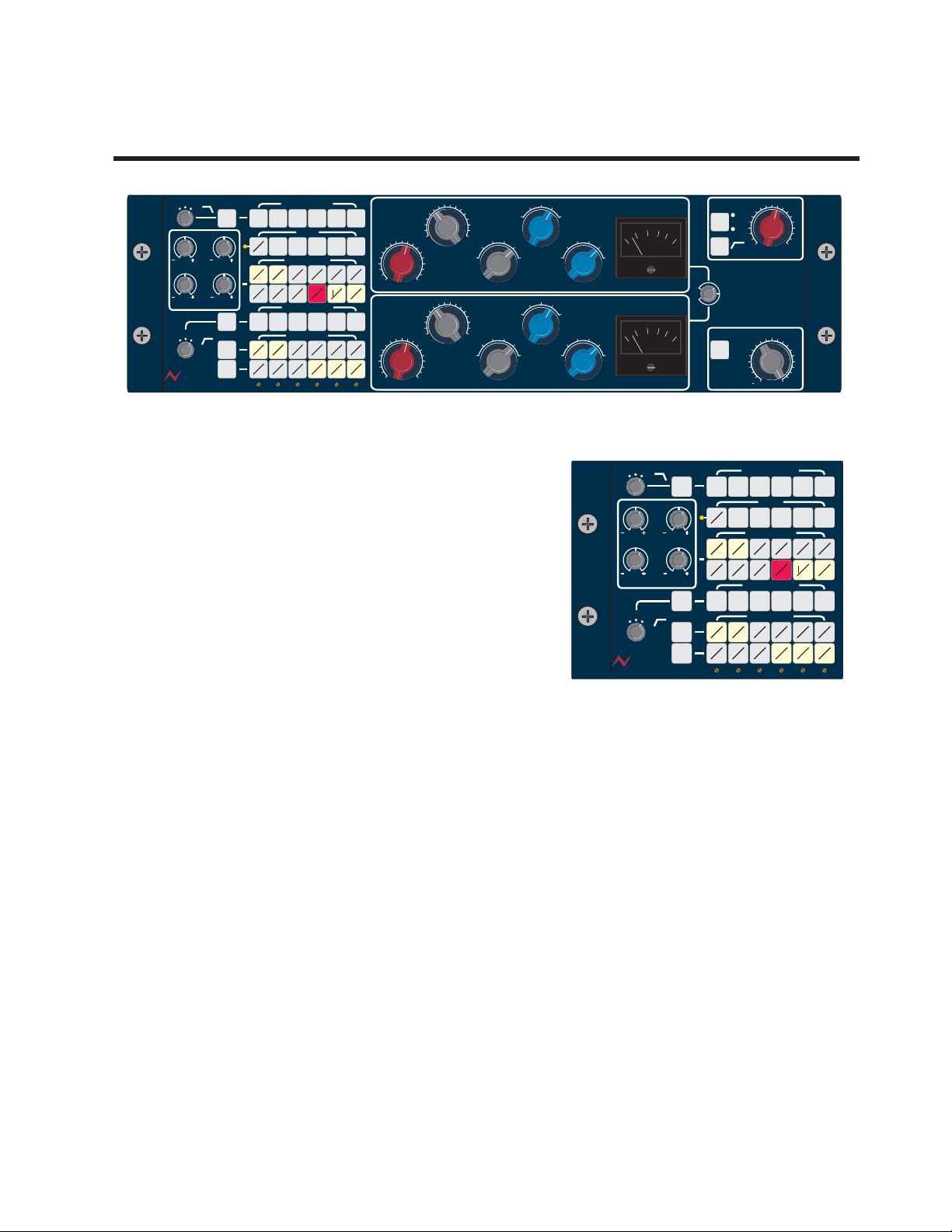
Bypass
All channels have relay bypass. Bypass is from the
output of the LFE filter to the input of the Output
Level Control *.
Hz
Hz
80
15
15
80
100
0
1/2
0
3
SC TRIMS dB
100
120
IN/OUT
0
15
15
15
5/6
0
15
15
15
4
IN/OUT
120
EXT
A
CTRL
EXT
B
CTRL
FILTER TO CHANNEL
5
3
1
2
4
M
A
B
A
B
BYPASS
3
2
SIDECHAIN LINK
A
A
B
B
SIDECHAIN FILTER
3
2
CONTROL LINK
A
A
B
B
5
4
A
A
B
B
5
4
A
A
B
B
1
MST
123456
123456
1
123456
123456
6
6
A
B
6
A
B
If a channel routed to a sidechain is bypassed, its connection to the sidechain is maintained. This
means that other channels controlled by that sidechain are unaffected and allows a channel to
control others without being compressed itself (as though it were another key input).
Two bypass modes are available, single or master. In single mode each switch bypasses its
respective channel. In master mode all channels are controlled together from the channel 1 bypass
button.
Master mode is toggled by pressing and holding the channel 1 bypass switch and is indicated by the
MST LED to the left of channel 1 being lit. If individual channels are placed in Bypass mode, the
Master Bypass function then becomes a Group Bypass control for the remaining channels.
-
* In Master Mode individual channels can be deselected from the master group and will remain
in local bypass indicated by permanently lit bypass buttons.
-
* The elements outside the bypass loop are designed to be audibly transparent. Typical
distortion in bypass is <0.0008% at 1kHz, typical 20Hz-20kHz band noise is <-90dBu.
Issue 2 Page 5
Page 8

8051 5.1 Compressor User Guide
Sidechain Link
The sidechainlink buttons route audio fromeach channel's sidechain audio path into one or both of
the sidechain timing circuits. If a single channel's SC LINK A or B button is pressed, that channel will
behave as a mono compressor.
If another channel is then linked to the same sidechain, the timing circuit responds to whichever
channel is larger at any moment (taking into account the setting of the SC trim controls). The
resulting control voltage is then applied equally to both channels,i.e. they behave as a stereo linked
compressor.
Sidechain Filter
Inserts a high-pass filter in the channel's sidechain path, preventing unwanted compression due to
LFE content. The response is 12dB/octave, shelves at -20dB (this is required to maintain the
sidechain's phase margin) and has a selectable -3dB frequency of 80, 100, or 120Hz.
Issue 2 Page 6
Page 9

8051 5.1 Compressor User Guide
Neve
Control Link
While the SC link buttons control the audio inputs to
each sidechain, the CV link buttons choose where
the D.C. control voltage generated by each
sidechain is routed. The CV link buttons also
determine which gain makeup control affects each
channel, in the same way that the SC link buttons
assign the threshold controls.
For the output of a sidechain tobe correct, it must be
fed back to the channels it is derived from. Pressing
an SC link button will therefore illuminate the
Hz
Hz
80
15
15
80
100
0
1/2
0
3
SC TRIMS dB
100
120
IN/OUT
0
15
15
15
5/6
0
15
15
15
4
IN/OUT
120
EXT
A
CTRL
EXT
B
CTRL
FILTER TO CHANNEL
5
3
1
2
4
M
A
B
A
B
3
2
SIDECHAIN LINK
A
B
SIDECHAIN FILTER
3
2
CONTROL LINK
A
B
BYPASS
A
B
A
B
5
4
A
A
B
B
5
4
A
A
B
B
1
MST
123456
123456
1
123456
123456
6
6
A
B
6
A
B
corresponding CV link button and lock it on.
Most compressors apply gain reduction based entirely on the signal level at their inputs. A level
detector examines the input and drives an output VCA that is assumed to have a complimentary
response (a 'feed-forward' system). The 8051 uses a feedback topology, monitoring the output of
each gain cell and continually adjusting the control voltage returned to give the required gain
reduction.
This means that the control voltage linkinghas to follow sidechain linkingto maintain a closed loop.
Once this feedback is in place the sidechain output can be linked to other channels using the
remaining unlit CV link buttons. These channels then follow the same dynamic envelope as the SC
Linked channels, but without their audio content affecting the compression.
A channel may also have control voltage linked from both sidechains. In this case the sidechain
providing the most gain reduction at any moment controls the channel, and the greater of the two
gain makeup settings will be applied.
-
The CV Link buttons are disabled unless either a channel or the key has been routed to the
associated sidechain, or when in external mode.
Issue 2 Page 7
Page 10

8051 5.1 Compressor User Guide
Neve
SC Trims and Threshold
Thresholds for each channel are determined by
sidechain pathgain which is applied intwo stages.
The two main threshold controls are first assigned to
each channel with the SC Link buttons, providing a
base threshold level for each of the sidechains. The
SC Trim controls then allow threshold adjustment
on individual channels of ±15dB, irrespective of
how they are linked. The trims are grouped as two
stereo pairs (channels ½ and 5/6) and two monos
(channels 3 and 4).
Once above the sidechain's threshold level, the link
button for the largest signal on that sidechain (after
the threshold gain has been applied) illuminates
red. Any signal that is above threshold and within
2dB of the dominant signal will also illuminate.
Hz
Hz
15
1/2
15
100
120
0
15
0
15
3
SC TRIMS dB
100
1208080
IN/OUT
1
2
1
2
MST
M
123456
A
A
123456
B
B
1
2
123456
A
A
123456
B
B
15
15
0
5/6
0
4
IN/OUT
EXT
CTRL
EXT
CTRL
15
15
A
B
FILTER TO CHANNEL
3
4
BYPASS
3
4
SIDECHAIN LINK
A
A
B
B
SIDECHAIN FILTER
3
4
CONTROL LINK
A
A
B
B
5
6
5
6
A
A
B
B
5
6
A
A
B
B
Issue 2 Page 8
Page 11

8051 5.1 Compressor User Guide
EXT Control
The EXT buttons provide an insert point in the control voltage signal,after the bias control butbefore
routing back to the channels.
During normal operation the control voltages generated by the sidechain are internally connected
to the CV Link switched for routing back to the channels. In EXT mode the control voltage is taken
from the rear connector instead of the sidechain outputs, allowing the unit to be slaved from a
second 8051 or 33609.
There is no EXT Control with 88R(S) console mounted compressors (AM5052 & AM5265).
-
Pin Function
1 0V Reference
9 CV send, sidechain A
12 Remote power-on
5 CV send, sidechain B
13 CV return, sidechain B
14 CV return, sidechain A
15 24V Reference
Short to pin 12 to pin 1 to take the unit out of standby mode remotely.
CONTROL
VOLTAGE I/O
WARNING
DISCONNECTMAINS LEAD
TOISOLATE UNIT.
NOUSER SERVICEABLE
PARTSINSIDE
HAZARDOUSVOLTAGES INSIDE
REFERTO MANUALS
CHASSIS INTERNAL
0V
PLEASE SEE
MANUAL
FUSE 1.6AA/S CERAMIC
INPUT VOLTAGE 100-250VAC
INPUT FREQUENCY47-63Hz
INPUT 2INPUT 3INPUT 4INPUT 5INPUT 6KEY INPUT
INPUT 1
OUTPUT 1OUTPUT 2OUTPUT 3OUTPUT 4OUTPUT 5OUTPUT 6
PUSHPUSHPUSHPUSHPUSHPUSHPUSH
Issue 2 Page 9
Page 12

8051 5.1 Compressor User Guide
8
dB
4
0
12
16
20
4ms
6ms
8ms
16ms
..2s
.4s
.8s
1.5s
8
dB
4
0
12
16
20
8
dB
4
0
12
16
20
4ms
4ms
6ms
6ms
8ms
8ms
16ms
16ms
max
.1s
.2s
..2s
.4s
.4s
.8s
.8s
1.5s
1.5s
3s
8
dB
4
0
12
16
20
.4s
.8s
1..5s
3s
8
dB
4
0
12
16
20
8
dB
4
0
12
16
20
.4s
.4s
.8s
.8s
1.5s
1..5s
3s
3s
8
dB
4
0
12
16
20
2ms
4ms
6ms
8ms
16ms
3:1
4:1
6::1
max
.1s
.2s
.4s
.8s
1.5s
3s
8
dB
4
0
12
16
20
8
dB
4
0
12
16
20
2ms
2ms
4ms
4ms
6ms
6ms
8ms
8ms
16ms
16ms
3:1
3:1
4:1
4:1
6:1
6::1
max
max
.1s
.1s
.2s
.2s
.4s
.4s
.8s
.8s
1.5s
1.5s
3s
3s
8
dB
4
0
12
16
20
+20
2ms
4ms
6ms
8ms
16ms
2:1
8
112
16
4
0
3:1
4:1
6:1
.2s
.4s
.8s
1.5s
8
dB
4
0
12
16
20
8
dB
4
0
12
16
20
+20
+20
2ms
2ms
4ms
4ms
6ms
6ms
8ms
8ms
16ms
16ms
1.5:1
2:1
2:1
8
8
8
12
112
16
16
4
4
0
0
3:1
3:1
4:1
4:1
6:1
6:1
max
.1s
.2s
.2s
.4s
.4s
.8s
.8s
1.5s
1.5s
3s
8
dB
4
0
12
16
20
-10
+20
2ms
4ms
6ms
8ms
16ms
+116
1.5:1
2:1
8
8
8
8
12
12
16
4
4
4
4
0
0
3:1
4:1
6:1
max
.1s
.2s
.4s
.8s
1.5s
3s
8
dB
4
0
12
16
20
8
dB
4
0
12
16
20
-10
-10
+20
+20
2ms
2ms
4ms
4ms
6ms
6ms
8ms
8ms
16ms
16ms
+16
+116
1.5:1
1.5:1
2:1
2:1
8
8
8
8
8
8
8
8
12
12
12
12
16
16
4
4
4
4
4
4
4
4
0
0
0
0
3:1
3:1
4:1
4:1
6:1
6:1
max
max
.1s
.1s
.2s
.2s
.4s
.4s
.8s
.8s
1.5s
1.5s
3s
3s
Threshold
A
4
8
12
16
-20
THRESHOLD dBu
B
4
8
12
16
-20
THRESHOLD dBu
4
8
0
8
12
0
8
12
MAKE-UP
GAIN dB
4
MAKE-UP
GAIN dB
12
16
3:1
+20
2:1
1.5:1
RATIO
8
12
16
3:1
+20
2:1
1.5:1
RATIO
4
8
0
-10
4
+16
4
8
0
-10
4
+16
6ms
4ms
8ms
2ms
4:1
6:1
4ms
2ms
4:1
6:1
max
max
ATTAC K
6ms
ATTAC K
.1s
8ms
.1s
16ms
.2s
RECOVERY
16ms
.2s
.4s
.4s
GAIN REDUCTION
8
12
4
0
.8s
1.5s
3s
16
20
dB
GAIN REDUCTION
8
12
4
0
.8s
1.5s
3s
16
20
dB
RECOVERY
Threshold is the level above which compression begins. Each
channel linked to a sidechain (using the SC Link buttons) takes
that sidechain's threshold. If a channel is linked to sidechains A
and B the lower value of the two controls is used. The threshold
controls have a range of -20dBu to +16dBu, adjustable in 2dB
steps. Each channel's threshold may be modified by up to
±15dB irrespectiveof its linking by usingthe SC Trim controls.
A red LED indicator is provided in each sidechain link
-
button. This indicates that a channel is above threshold,
and either is the dominant signal or within 2dB of the
dominant signal on that sidechain.
Gain Makeup
Gain Makeup is used to restore the average level or loudness of
a compressed signal. Linking control voltage to a channel (with
the CV Link buttons) assigns either the A or B Gain Makeup
control to that channel. If control voltage from both sidechains is
linked the larger of the two values is used; this is because the
sidechain with the greater gain reduction will be controlling the
channel. The gain applied is adjustable from -10 to +20dB in
2dB steps.
Ratio
Ratio controls the amount of gain reduction applied as the input
level increases.
Issue 2 Page 10
At 2:1 for example, a change of 10dB at the input produces a
change of 5dB at the output. Values available are 1.5:1, 2:1,
3:1, 4:1, 6:1, and 'max' (approximately 8:1).
The 8051 has a soft-knee characteristic, and its ratio gradually
increases as the compression becomes heavier at all settings.
The numbers given should therefore be considered average
values.
Page 13

8051 5.1 Compressor User Guide
8
dB
4
0
12
16
20
4ms
6ms
8ms
16ms
..2s
.4s
.8s
1.5s
8
dB
4
0
12
16
20
8
dB
4
0
12
16
20
4ms
4ms
6ms
6ms
8ms
8ms
16ms
16ms
max
.1s
.2s
..2s
.4s
.4s
.8s
.8s
1.5s
1.5s
3s
8
dB
4
0
12
16
20
.4s
.8s
1..5s
3s
8
dB
4
0
12
16
20
8
dB
4
0
12
16
20
.4s
.4s
.8s
.8s
1.5s
1..5s
3s
3s
8
dB
4
0
12
16
20
2ms
4ms
6ms
8ms
16ms
3:1
4:1
6::1
max
.1s
.2s
.4s
.8s
1.5s
3s
8
dB
4
0
12
16
20
8
dB
4
0
12
16
20
2ms
2ms
4ms
4ms
6ms
6ms
8ms
8ms
16ms
16ms
3:1
3:1
4:1
4:1
6:1
6::1
max
max
.1s
.1s
.2s
.2s
.4s
.4s
.8s
.8s
1.5s
1.5s
3s
3s
8
dB
4
0
12
16
20
+20
2ms
4ms
6ms
8ms
16ms
2:1
8
112
16
4
0
3:1
4:1
6:1
.2s
.4s
.8s
1.5s
8
dB
4
0
12
16
20
8
dB
4
0
12
16
20
+20
+20
2ms
2ms
4ms
4ms
6ms
6ms
8ms
8ms
16ms
16ms
1.5:1
2:1
2:1
8
8
8
12
112
16
16
4
4
0
0
3:1
3:1
4:1
4:1
6:1
6:1
max
.1s
.2s
.2s
.4s
.4s
.8s
.8s
1.5s
1.5s
3s
8
dB
4
0
12
16
20
-10
+20
2ms
4ms
6ms
8ms
16ms
+116
1.5:1
2:1
8
8
8
8
12
12
16
4
4
4
4
0
0
3:1
4:1
6:1
max
.1s
.2s
.4s
.8s
1.5s
3s
8
dB
4
0
12
16
20
8
dB
4
0
12
16
20
-10
-10
+20
+20
2ms
2ms
4ms
4ms
6ms
6ms
8ms
8ms
16ms
16ms
+16
+116
1.5:1
1.5:1
2:1
2:1
8
8
8
8
8
8
8
8
12
12
12
12
16
16
4
4
4
4
4
4
4
4
0
0
0
0
3:1
3:1
4:1
4:1
6:1
6:1
max
max
.1s
.1s
.2s
.2s
.4s
.4s
.8s
.8s
1.5s
1.5s
3s
3s
Attack
A
4
8
12
16
-20
THRESHOLD dBu
B
4
8
12
16
-20
THRESHOLD dBu
4
8
0
8
12
0
8
12
MAKE-UP
GAIN dB
4
MAKE-UP
GAIN dB
12
16
3:1
+20
2:1
1.5:1
RATIO
8
12
16
3:1
+20
2:1
1.5:1
RATIO
4
8
0
-10
4
+16
4
8
0
-10
4
+16
6ms
4ms
2ms
4:1
2ms
4:1
8ms
16ms
6:1
ATTAC K
max
4ms
6:1
ATTAC K
max
.4s
.2s
.1s
RECOVERY
6ms
8ms
16ms
.4s
.2s
.1s
GAIN REDUCTION
8
12
4
0
.8s
1.5s
3s
16
20
dB
GAIN REDUCTION
8
12
4
0
.8s
1.5s
3s
16
20
dB
RECOVERY
This is the time between a signal 6dB above the threshold level
being applied, and the output signal falling to within 2dB of its
final level. With slower attack settings compression is more
dependant on the average signal level, while with faster settings
it is more dependant on the peaks. Setting of 2ms, 4ms, 6ms,
8ms and 16ms are available.
Recovery
If a signal 6dB above the threshold has been applied for long
enough that the output has reached its steady-state level,
recovery is the time taken for it to get to within 2dB of its final level
if the input is dropped by 6dB. Recovery compliments the attack
control by filtering the control voltage; longer recovery times
prevent pumping effects where gain reduction follows the
program material too closely. Settings of 100ms, 200ms,
400ms, 800ms, 1.5s and 3s are available.
Gain Reduction Meters
Gain reduction meters are provided post the A/BBias control and pre the CV Link routing buttons to
show the level of attenuation being applied. The meters have 20dB f.s.d.
Issue 2 Page 11
Page 14

8051 5.1 Compressor User Guide
8
8
12
4
4
0
DISCRETE
8
8
12
4
4
0
Key Input
4
A Key Input is provided to allow adjustable control from an external
source. Like the sidechains the key input has a threshold level
control ranging from -20 to +16 to set the intended level at which
compression control is required.
KEY I/P
SIDE
CHAIN
SEL
IN/OUT
100Hz
8
A
12
B
16
-20 +16
THRESHOLD dBu
0
4
8
12
It can be used in several ways:
A/B
0
BIAS
8051
DISCRETE
MULTI-CHANNEL
COMPRESSOR
OUTPUT LEVEL dB
0-5.5
Injecting tone to provide a remotely variable base-level of
q
compression on one or both sidechains.
'Ducking' from an audio source such as dialogue.
q
When connected in parallel with one of the inputs, it allows
q
A
B
POWER
that input to be routed onto both sidechains with different
compression thresholds.
Key Filter
The key input is provided with a selectable 12dB/octave high-pass LFE filter, fixed at 100Hz.
Bias Control
The bias control is used to balance the control voltages from the two sidechains by applying up to
6dB of cut and boost, effectively modifying their ratios.
If only a single sidechain is in use, for example when used as a stereo compressor, the bias control
allows ratio values between the standard settingsto be selected with continuouslyvariable control.
Output Level
This control provides a variable active pad across all six outputs, from 0dB to -5.5dB in 0.25dB
steps. The pad is outside of the relay bypass loop and so always controls all six channels together in
order to maximise the unit's output level without clipping.
Power
The power switch is illuminated dim red when the mains is present to indicate that the unit is in
standby mode. While in standby all switches are disabled, switch settings are retained and the unit
consumes minimal power.
Pressing the power switch brings the unit out of standby (power switch illuminates green). Pressing
and holding returns it to standby mode.
-
The unit can be brought out of standby remotely by connecting pins 1 and 12 on the rear panel
D-Type connector.
Issue 2 Page 12
Page 15

8051 5.1 Compressor User Guide
0-5.5
0
8
dB
4
0
12
16
20
8
dB
4
0
12
16
20
A
B
-10
-10
+20
+20
2ms
2ms
4ms
4ms
6ms
6ms
8ms
8ms
16ms
16ms
-20
-20
-20
+16
+16
+16
1.5:1
1.5:1
2:1
2:1
8
8
8
8
8
8
8
8
8
8
12
12
12
12
12
12
12
12
16
16
16
16
16
4
4
4
4
4
4
4
4
4
4
0
0
0
0
0
3:1
3:1
4:1
4:1
6:1
6:1
max
max
.1s
.1s
.2s
.2s
.4s
.4s
.8s
.8s
1.5s
1.5s
3s
3s
DISCRETE
Neve
+16
8
8
12
4
4
0
DISCRETE
8
dB
4
0
12
16
20
4ms
6ms
8ms
16ms
-20
+16
8
8
12
12
16
4
4
0
..2s
.4s
.8s
1.5s
0
8
dB
4
0
12
16
20
8
dB
4
0
12
16
20
4ms
4ms
6ms
6ms
8ms
8ms
16ms
16ms
-20
+16
8
8
12
12
16
4
4
0
max
.1s
.2s
..2s
.4s
.4s
.8s
.8s
1.5s
1.5s
3s
DISCRETE
8
dB
4
0
12
16
20
-20
+16
8
8
12
12
16
4
4
0
.4s
.8s
1..5s
3s
0
8
dB
4
0
12
16
20
8
dB
4
0
12
16
20
-20
+16
8
8
12
12
16
4
4
0
.4s
.4s
.8s
.8s
1.5s
1..5s
3s
3s
DISCRETE
8
dB
4
0
12
16
20
2ms
4ms
6ms
8ms
16ms
-20
+16
8
8
12
12
16
4
4
0
3:1
4:1
6::1
max
.1s
.2s
.4s
.8s
1.5s
3s
0
8
dB
4
0
12
16
20
8
dB
4
0
12
16
20
2ms
2ms
4ms
4ms
6ms
6ms
8ms
8ms
16ms
16ms
-20
+16
8
8
12
12
16
4
4
0
3:1
3:1
4:1
4:1
6:1
6::1
max
max
.1s
.1s
.2s
.2s
.4s
.4s
.8s
.8s
1.5s
1.5s
3s
3s
DISCRETE
8
dB
4
0
12
16
20
+20
2ms
4ms
6ms
8ms
16ms
-20
+16
2:1
8
8
8
112
12
12
16
16
4
4
4
0
0
3:1
4:1
6:1
.2s
.4s
.8s
1.5s
0
8
dB
4
0
12
16
20
8
dB
4
0
12
16
20
+20
+20
2ms
2ms
4ms
4ms
6ms
6ms
8ms
8ms
16ms
16ms
-20
+16
1.5:1
2:1
2:1
8
8
8
8
8
12
112
12
12
16
16
16
4
4
4
4
0
0
0
3:1
3:1
4:1
4:1
6:1
6:1
max
.1s
.2s
.2s
.4s
.4s
.8s
.8s
1.5s
1.5s
3s
DISCRETE
8
dB
4
0
12
16
20
-10
+20
2ms
4ms
6ms
8ms
16ms
-20
+116
+16
1.5:1
2:1
8
8
8
8
8
8
12
12
12
12
16
16
4
4
4
4
4
4
0
0
0
3:1
4:1
6:1
max
.1s
.2s
.4s
.8s
1.5s
3s
0
8
dB
4
0
12
16
20
8
dB
4
0
12
16
20
-10
-10
+20
+20
2ms
2ms
4ms
4ms
6ms
6ms
8ms
8ms
16ms
16ms
-20
+16
+116
+16
1.5:1
1.5:1
2:1
2:1
8
8
8
8
8
8
8
8
8
8
12
12
12
12
12
12
16
16
16
4
4
4
4
4
4
4
4
4
4
0
0
0
0
0
3:1
3:1
4:1
4:1
6:1
6:1
max
max
.1s
.1s
.2s
.2s
.4s
.4s
.8s
.8s
1.5s
1.5s
3s
3s
DISCRETE
+116
8
8
12
4
4
0
Mastering Compressor Controls (AM5292)
The 8051 Mastering Compressor is slightly different to the standard 8051 in 2 ways:
It has 21 position detented pots for the Trim and Bias controls to aid total mechanical
q
recall of the unit.
It has -1dB switches fitted to the Threshold and Gain Make-Up controls to allow for more
q
accurate settings, for example, in a mastering application the entire range of the switches
can be turned from 2dB steps into 1dB steps by the selection of the -1dB switches.
21 Position
Detented Pots
-1dB Switches
100
120
Hz
10
10
0
1/2
0
3
SC TRIMS dB
IN/OUT
0
10
10
10
5/6
0
10
10
10
4
IN/OUT
100
1208080
Hz
CTRL
CTRL
EXT
A
EXT
B
FILTER TO CHANNEL
5
3
2
3
2
SIDECHAIN LINK
A
B
SIDECHAIN FILTER
3
2
CONTROL LINK
A
B
BYPASS
A
B
A
B
4
5
4
A
B
5
4
A
B
1
1
MST
M
123456
A
123456
B
1
123456
A
123456
B
A
6
4
8
6
12
16
A
A
-20
THRESHOLD dBu
B
B
B
6
4
8
12
A
A
16
B
B
-20
THRESHOLD dBu
4
8
0
12
4
-1dB
8
0
-10
4
12
+16
4
-1dB
8
0
-10
4
12
+16
8
0
8
MAKE-UP
GAIN dB
-1dB
4
MAKE-UP
GAIN dB
-1dB
16
3:1
+20
2:1
1.5:1
RATIO
8
12
16
3:1
+20
2:1
1.5:1
RATIO
6ms
4ms
8ms
2ms
4:1
6:1
2ms
4:1
6:1
16ms
.4s
.2s
ATTAC K
.1s
max
RECOVERY
6ms
4ms
8ms
16ms
.4s
.2s
ATTAC K
.1s
max
GAIN REDUCTION
.8s
1.5s
dB
3s
8
12
4
0
GAIN REDUCTION
8
12
4
0
.8s
1.5s
dB
3s
KEY I/P
SIDE
CHAIN
16
SEL
20
IN/OUT
A
B
16
20
POWER
RECOVERY
100Hz
A/B
0
BIAS
8
A
12
B
16
-20
THRESHOLD dBu
MULTI-CHANNEL
COMPRESSOR
OUTPUT LEVEL dB
4
0
8051M
DISCRETE
4
8
12
+16
0-5.5
Issue 2 Page 13
Page 16

8051 5.1 Compressor User Guide
100
100
120
120
0
0
0
0
15
15
151515
15
0
BA
8
dB
4
0
12
16
20
88
88
12 12
44
44
00
-10 -10+20 +20
88
88
12 12
16 16
44
44
00
3:1 3:1
4:1 4:1
6:1 6:1
Max Max
2ms 2ms
4ms 4ms
6ms 6ms
8ms 8ms
16ms 16ms
.4s .4s
.8s .8s
1.5s 1.5s
3s 3s
8
dB
4
0
12
16
20
-20 +16
8
8
12
12
16
4
4
0
100
100
120
120
0
0
0
0
15
15
151515
15
BA
888
88
12 12
44
444
00
44
BA
0
0
151515
BA
88
12 12
44
88
112 12
16 16
44
000
BA
100
100
120
120
0
0
0
0
15
15
151515
15
BA
88
12 12
44
44
00
-10 -10+20 +20
88
88
12 12
16 16
44
44
00
3:1 3:1
4:1 4:1
6::1 6:1
Max Max
4mms 4ms
6ms 6ms
BA
0
0
151515
15
BA
88
12 12
44
88
12 12
16 16
44
00
6:1 6:1
Max Max
4ms 4ms
6ms 6ms
8ms 8ms
116ms 16ms
BA
100
100
120
120
0
0
0
0
15
15
151515
15
BA
88
12 12
44
44
00
-10 -10+20 +20
88
88
12 12
16 16
44
44
00
3:1 3:1
4:1 4:1
6:1 6:1
Max Max
2ms 2ms
4ms 4ms
6ms 6ms
8ms 8ms
16ms 16ms
.4s .4s
.8s .8s
1..5s 1.5s
3s 3s
BA
BA
12
16
20
8
8
12
4
4
0
BA
12
16
20
8
12
4
4
0
BA
16
20
8
12
4
0
8051 Compressor - 88R(S) Console mounted AM5052
100
120
Hz
15
15
0
15
1/2
0
15
3
SC TRIMS dB
IN/OUT
0
15
15
5/6
0
15
15
4
IN/OUT
100
1208080
Hz
4 4
0 0
4 4
8 8
12 12
16 16
-20 -20+16 +16
THRESHOLD dBu THRESHOLD dBu
2:1 2:1
1.5:1 1.5:1
.2s .2s
.1s .1s
8 8
12 12
4 4
0 0
4 4
8 8
-10 -10+20 +20
MAKE-UP
4:1 4:1
3:1 3:1
RATIO RATIO
.4s .4s
GAIN dB
6:1 6:1
Max Max
6ms 6ms
4ms 4ms
2ms 2ms
.8s .8s
1.5s 1.5s
ATTAC K ATTAC K
3s 3s
FILTER TO CHANNEL
5
3
1
2
4
1
MST
123456
123456
123456
123456
8 8
12 12
8ms 8ms
16ms 16ms
BYPASS
5
3
2
M
4
SIDECHAIN LINK
BBBBBB
AAAAAA
SIDECHAIN FILTER
5
3
1
2
4
CONTROL LINK
BBBBBB
AAAAAA
16 16
MAKE-UP
GAIN dB
6
6
6
BA
Issue 2 Page 14
-
As this unit is designed for fixed 5.1 compressor applications in an 88R(S) console the EXT A
CTRL and EXT B CTRL controls are not selectable (blank buttons).
RECOVERY RECOVERY
GAIN REDUCTION
8
12
4
16
0
20
dB
AB
0
OUTPUT LEVEL dB
5.5
0
A/B
BIAS
2 TRACK MIXER
-
-
0
40 40 40 40
ON ON ON ON
1-2
(L-R)
-
0
0
4
3
(S)
(C)
GAIN REDUCTION
8
4
0
dB
IN/OUT
100Hz
8
12
16
-20 +16
THRESHOLD dBu
-
0
5-6
(LS-RS)
POST
12
16
20
SIDE
KEY
CHAIN
I/P
SEL
BA
4
0
4
8
12
-
+10
2T TO
INS
MON
2T
OUTPUT
Page 17

8051 5.1 Compressor User Guide
I/O Wiring (AM5052 & AM5265)
56 Way Free Plug Varicon
Signal Signal Name Pin Number
Hi Lo Scn
1 1 Left Input C J D
2 3 Centre Input P V K
3 2 Right Input U Z d
4 4 S Input Y c f
5 5 LS Input s m j
6 6 RS Input x t n
7 1 Left Output CC y JJ
8 3 Centre Output MM HH NN
9 2 Right Output B F A
10 4 S Output L R E
11 5 LS Output S W a
12 6 RS Output X b e
13 Key Input r l h
14 v p k
15 z u DD
16 LL EE KK
Issue 2 Page 15
Page 18

8051 5.1 Compressor User Guide
Specifications
I/O
The key input and LFE filterinputs are electronically balanced withan input impedance of 10kohms.
All other inputs are transformer balanced with 3.6kohms input impedances.
All outputs are electronically balanced post the output transformers, with maximum output of
+26dBu into 600ohms. The unit is calibrated for bridging loads greater than 10kohms.
Control Voltage I/O is provided for linking multiple units, or linking to 33609 compressors.
Connection is by 15 pin D-Type (see the section on EXT control for details).
Audio Performance
Control
Equivalent input noise (20kHz band): < -78dBu
THD+N (for 20dBu input @1kHz): < 0.03%
Maximum Output Level: > 26dBu into 600 ohms
Interchannel Crosstalk: < -80dB at 15kHz
LFE Filter: 12dB/octave low-pass, -3dB frequency selectable
to 80Hz, 100Hz or 120Hz.
Sidechain & Key Filters: 12dB/octave high-pass, -3dB frequency selectable to
80Hz, 100Hz or 120Hz.
Threshold: -20dBu to +16dBu master control, with ±15dB
trims on all channels.
Make-up gain: -10dB to +20dB.
Ratio: 1.5:1, 2:1, 3:1, 4:1, 6:1, MAX (~8:1).
Attack: 2ms, 4ms, 6ms, 8ms and 16ms.
Release: 100ms, 200ms, 400ms, 800ms, 1.5s and 3s.
Output Level Trim: 0dB to -5.5dB pad, in 0.25dB steps.
Issue 2 Page 16
Page 19

8051 5.1 Compressor User Guide
Issue 2 Page 17
 Loading...