

Page 1
ELLIPSE
Service Manual
Via E. Barsanti 17/A
00012 Guidonia – ROME (ITALY)
www.ams-analyzers.com
Page 2

CONFIGURATION SHEET
CHAPTER DESCRIPTION REVISION
INDEX TABLE OF CONTENTS 03
01 INTRODUCTION
02 SYSTEM DESCRIPTION
03 INSTALLATION
04 ELECTRICAL SCHEMES AND DRAWINGS
05 DIAGNOSTIC PROGRAM
06 SETTINGS AND ADJUSTMENTS
07 MAINTENANCE
08 HOST COMMUNICATION
09 ERROR SIGNALING AND TROUBLESHOOTING
03
03
03
03
03
03
03
04
03
Ellipse Service Manual Rev.04 01 October 2009 Page 1
Page 3

TABLE OF CONTENTS
Chapter 01 INTRODUCTION
Chapter 02 SYSTEM DESCRIPTION
Chapter 03 INSTALLATION
Chapter 04 ELECTRICAL SCHEMES AND DRAWINGS
INDEX
Chapter 05 DIAGNOSTIC PROGRAM
Chapter 06 SETTINGS AND ADJUSTMENTS
Chapter 07 MAINTENANCE
Chapter 08 HOST COMMUNICATION
Chapter 09 ERROR SIGNALING AND TROUBLESHOOTING
Ellipse Service Manual Rev.03 01 June 2009 Page 1
Page 4

Chapter 01 – INTRODUCTION
CHAPTER 01
- INTRODUCTION -
INDEX
1 INTRODUCTION ................................................................................................................. 1
1.1 THE AIM OF THE TECHNICAL MANUAL
1.1.2 MANUAL OUTLINE……………………………..……………………..……………..………………....2
1.2 SYSTEM INTRODUCTION ................................................................................................ 3
1.3 PRECAUTIONARY MEASURES ....................................................................................... 3
1.3.1 CHEMICAL RISKS .............................................................................................................. 5
1.3.2 ELECTRICAL RISKS........................................................................................................... 5
1.3.3 MECHANICAL RISKS......................................................................................................... 4
1.4 GUARANTEE ...................................................................................................................... 5
1.5 TECHNICAL OPERATING FEATURES………………………………………….…. ..... 6
1.5.1 COMPUTER & SOFTWARE FEATURES ........................................................................ .9
1.5.2 OPTIONS............................................................................................................................... 8
………………………………………...………..…..2
1.5.3 DIMENSIOS, WEIGHT & ENVIRONMENT.................................................................... 10
1.5.4 INSTALLATION REQUIREMENTS................................................................................ 10
Ellipse Service Manual Rev. 03 01June 2009 Page 1
Page 5

Chapter 01 – INTRODUCTION
1 INTRODUCTION
1.1 THE AIM OF THE TECHNICAL MANUAL
This manual has been written in order to supply the technical staff, the persons who are responsible
for the maintenance and for resolving instrument failures, a complete and detailed guide of the
Ellipse analyzer, in accordance with the standard UNI EN591 (which requires a manual to be
supplied with vitro diagnostic instruments for professional use).
1.1.2 MANUAL OUTLINE
The technical manual is composed of 10 chapters that not only describe the operative technical
characteristics of the system, but also the reparation and maintenance procedures to use for the
modules that they are composed of.
. Chapter 1 INTRODUCTION
The manual structure is described, and recommendations are given regarding the general
use of the analyzer. The technical characteristics of the operative system are given in this
chapter.
. Chapter 2 DESCRIPTION OF THE SYSTEM
Describes the system, in particular, the analytical cycle of the single modules and
electronic boards.
. Chapter 3 INSTALLATION
Describes the unpacking procedures and the required characteristics for the place of
installation.
. Chapter 4 ELECTRONICS SCHEMES AND DRAWINGS
Gives the electronics schemes and assembly drawings of the electronics board and the
assembly drawings of the modules that the system is composed of.
Ellipse Service Manual Rev. 03 01June 2009 Page 2
Page 6

Chapter 01 – INTRODUCTION
. Chapter 5 DIAGNOSTIC PROGRAM
Describes the folders in the Diagnostic Program that are responsible for the checks and the
calibration of the modules in the system.
. Chapter 6 SETTINGS AND ADJUSTMENTS
Gives the procedures for replacement, adjustment and check of the system modules.
. Chapter 7 MANTENANCE
Describes the routine maintenance that needs to be done on a regular basis in order to
guarantee the correct functioning of the analyzer.
. Chapter 8 COMUNICATION WITH HOST
Describes the communication protocol between the analyzer and the Host computer.
• Chapter 9 ERROR CODES AND GUIDE TO RESOLVE ANOMALIES
Lists the system’s error codes, describes the errors in the results and gives a guide for how to
implement corrective actions.
The technical staff responsible for resolving the structural anomalies is highly suggested to
thoroughly examine the contents of this manual before operating the system.
Ellipse Service Manual Rev. 03 01June 2009 Page 3
Page 7
Chapter 01 – INTRODUCTION
1.2 SYSTEM INTRODUCTION
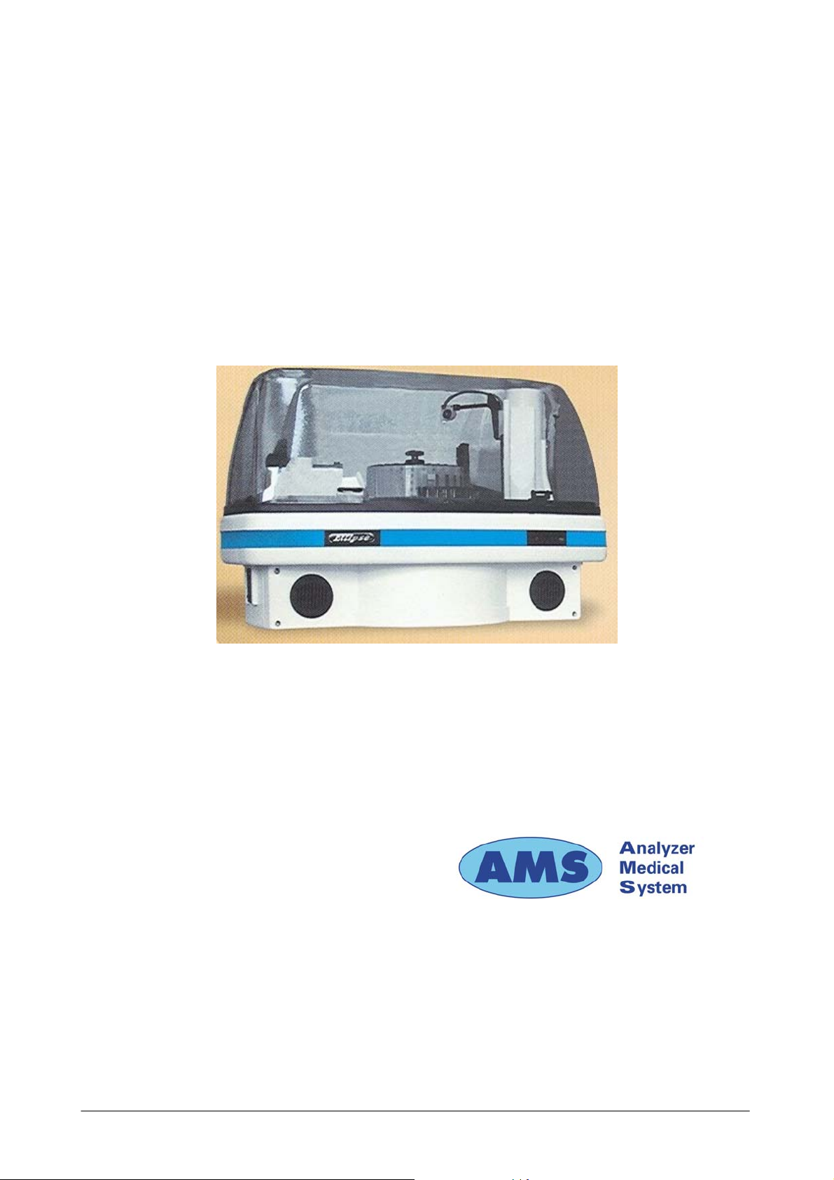
The “Ellipse” system is a continuous-loading, random access, bench top instrument for performing
chemical and Immunoturbidimetric clinical analysis. It is totally automatic and computer
controlled.
Via E. Barsanti 17/A
00012 Guidonia – ROME (ITALY)
Ellipse Service Manual Rev. 03 01June 2009 Page 4
Page 8

Chapter 01 – INTRODUCTION
1.3 PRECAUTIONARY MEASURES
1.3.1 CHEMICAL RISKS
The individual operator is responsible for assuring that all possible precautionary measures are
taken against eventual risks associated with the use of the “Ellipse” instrument in clinical laboratory
settings. The manufacturer will provide the reagents kit and specific written information on the use
of each of the reagents.
It is important that the samples be well coagulated and then carefully centrifuged.
Samples which contain fibrinogen clots can obstruct the probe and lead to inexact sampling.
If blood samples containing gel are used, it is suggested that the manufacturer’s recommendations
be followed.
Immediately clean and remove any accidental leakage of reagent or other liquid.
1.3.2 ELECTRICAL RISKS
As with any electrical device, the risk of electric shock exists.
Is therefore necessary to take every precautionary measure possible when working with this, or any
other, electrical instrument to avoid contact with power supply wires, electrical components or
electronic boards.
1.3.3 MECHANICAL RISKS
Several precautionary measures should be taken when operating the analyzer:
avoid wearing very loose clothing or jewelry that could become tangled in the instrument’s moving
parts (e.g. the sample probe); whenever possible, operate the instrument with the main cover panel
lowered.
WARNING: Never attempt to service or substitute any part(s) of the analyzer when the
instrument is turned on.
Any and all technical repairs or servicing must be performed by specialized personnel only.
Ellipse Service Manual Rev. 03 01June 2009 Page 5
Page 9

Chapter 01 – INTRODUCTION
1.4 WARRANTY
AMS guarantees the replacement of all defective components and/or materials for a period of time
not above of 14 months starting from the date of invoicing. Saying guarantee, as well as Technical
Assistance, generally is intended furnished as net ex factory Rome.
This guarantee does not include consumable and instrument parts in contact with liquids. All
components not included in the guarantee are reported in the following table.
Besides guarantee does not cover damage caused by :
- improper use of the ELLIPSE instrument (or however not according to the Producer or
Seller instructions)
- bad transport
- insufficient (or missing) preventive maintenance by the User
In particular any damages due to the transport must be immediately reported to the carrier when he
delivers.
Ellipse Service Manual Rev. 03 01June 2009 Page 6
Page 10

Chapter 01 – INTRODUCTION
CONSUMABLES AND ACCESSORIES PARTS LIST OUT OF GUARANTEE
Description
Type Quantity Code
Reagents containers 35 ml 12 pieces C101-00190-00
Reagents containers 6 ml 12 " C101-00191-00
Samples cups 0.8 ml
1000 "
AS-65-0002
Short samples cups 1 ml 1000 " AS-65-0100
Adapter for short samples cups 1 " 9-01-0609-00
Reaction sectors 6 " C101-00217-00
Washing solution bottle 2 lt 1 " 9-35-0041-00
Bottle level sensor 1 " 9-05-0078-00
Tubing Kit for peristaltic pump 2 " 65-01835-00
Tubing Kit – complete 1 " 65-01836-00
Cleaning solution 250 ml 2 " ASRN0020
Rinse solution 50 ml 1 " ASRN0021
Sampling probe (internal needle) 1 " 05-00707-00
Complete Sampling probe 1 " 10-00703-00
Drying Pad 1 " 10-01920-00
Halogen Lamp (6 V - 10 W) 1 " 9-35-0016-00
Interferential filters Kit 1 " 9-65-0029-00
Fuse 6,3 A-T 5x20 10 " C130-01238-08
Inlet/outlet fitting for Rinse & Clean conts 1 " 01-01224-00
Cuvettes protection cover 1 " 05-01249-00
Reagent protection cover 1 " 10-00584-00
Reagent plate 1 " 10-00585-00
Samples rack 1 " 05-01829-00
Washing station, first or second cannulas (A) 1 05-01633-00
Washing station, third cannula (B) 1 05-01633-01
Washing station, fourth cannula (C)
1
05-01638-00
Washing station, fifth cannula without pad (D) 1 05-01919-00
Diluter Micro-Pump
1 " 05-01710-40
Air Micro-Pump (µP 6) 1 " 05-01711-20
Micro-Pump (µP 2 ÷5) 1 " 05-01826-16
Predilution rack 1 " 05-01735-00
Solenoid Valve –2 way 1 " 9-35-0035-00
Solenoid Valve –3 way 1 " 9-35-0036-00
Ellipse Service Manual Rev. 03 01June 2009 Page 7
Page 11

Chapter 01 – INTRODUCTION
1.5 TECHNICAL OPERATING FEATURES
DESCRIPTION
ASSAY TYPE
TEST ENTRY MODE
THROUGHPUT
♦ Fully automatic, random access, continuous loading,
benchtop analyzer for clinical chemistry and
immunoturbidimetric assays;
♦ End Point, Initial Rate, Kinetic, Bichromatic, Differential;
♦ Selective, Batch, Profiles, STAT
♦ 138 tests per hour
WORKING TEMPERATURE ♦ 37° C
♦ 24 removable containers by 40 ml and 6 ml;
ON LINE REAGENTS
♦ 12 positions for Controls and Standards;
♦ Positive identification by a Bar Code Reader
♦ Primary tubes (diameter from 8 to 16 mm; height up to
100 mm) cups from 1 to 4 ml;
SAMPLE CONTAINERS
♦ 4 racks, each having 8 positions for continuous sample
loading
SAMPLE LOADING
♦ Positive identification by a Bar Code Reader
MINIMUM REACTION VOLUME
MAXIMUM REACTION VOLUME
SAMPLING ARM
DILUTER
PRECISION
♦ 220 µl
♦ 550 µl
♦ A single mechanical arm provides all the sampling
operations and is equipped with:
• Capacitive liquid level sensing
• Reagent pre-warming at 37° C
• Automatic probe washing
♦ Integrated syringe-free module having the following
specifications:
• Sample volume: 2 µl ÷ 99 µl (1 µl incr.)
• Reagent 1 volume: 3 µl ÷ 500 µl (1 µl incr.)
• Reagent 2 volume: 3 µl ÷ 330 µl (1 µl incr.)
• Reagent 3 volume: 3 µl ÷ 330 µl (1 µl incr.)
♦ CV < 1 % at 2 µl
READING SYSTEM
♦ Direct reading
Ellipse Service Manual Rev. 03 01June 2009 Page 8
Page 12

Chapter 01 – INTRODUCTION
♦ Photometer: double beam, interferential filters
♦ Wavelength: 8 narrow band interferential filters
OPTIC SYSTEM
from 340 nm to 620 nm , plus one available
optional filter position
♦ Light source: 6V/10 W halogen bulb
♦ Linearity range: up to 3,500 Abs
♦ Resolution: 0.0005 Abs
OPTICAL PATH
WASHING STATION
REACTION PLATE
1.5.1. COMPUTER & SOFTWARE FEATURE
TYPE
CPU
MEMORY
♦ 6 mm.
♦ Composed of five probes that empty, wash and
dry the reaction cuvettes.
♦ 6 singular replaceable racks with 20 cuvettes
each
♦ Cuvettes Q.C. continuously computer controlled
♦ Incubation temperature: 37°C
MINIMUM REQUIREMENTS
♦ IBM Compatible
♦ Pentium IV 500 MHz, 512 Kb Cache
♦ RAM 256 Mb
♦ Hard Disk 20 Gb
♦ Floppy Disk 3 1/2” 1.44 Mb
♦ Colour SVGA 15’’ low radiation
MONITOR
Resolution 800 x 600 pixels;
max number of colors 65536 (16 bit)
PRINTER
INTERFACE
SOFTWARE
AVAILABLE LANGUAGES
♦ 80 Columns impact graphic (EPSON LX 300)
♦ One Bi-directional RS 232C serial ports and one
parallel (one second serial port for the Host link)
♦ Multitasking WINDOWS XP Home edition
♦ Italian, English, Chinese, Czech. Software to be
released soon in these languages: Russian, Portuguese,
French, Polish. Upon request it is possible to release
the software in other languages.
♦ Disable all the energy saving options
SETTINGS
♦ Disable the screen saver
♦ Select English “USA” as language, dot as decimal
symbol and date and time in Regional setting
Ellipse Service Manual Rev. 03 01June 2009 Page 9
Page 13

Chapter 01 – INTRODUCTION
NOTE: Even though the computers demonstrate the same technical and operative characteristics,
some of these could have different hardware installed.
This could cause problems for the Ellipse software when running tests (A message appears
indicating “Random” error or blocks the program).
Therefore, if the PC is bought separately/locally, it is highly recommended to test the system at
your offices before preceding with the installation at the final client’s.
Consequently, AMS denies any responsibility for software problems that are due to buying the
computer separately from the instrument.
1.5.2 OPTIONAL MODULES
♦ POSITIVE BARCODE READER
1.5.3 DIMENSIONS, WEIGHT & OPERATING ENVIRONMENT
DIMENSIONS
WEIGHT
OPERATING ENVIRONMENT
1.5.4 INSTALLATION REQUIREMENTS
POWER REQUIREMENTS
♦ Height: 53 cm
♦ Depth: 57 cm
♦ Length: 75 cm
♦ 35 Kilos
♦ Temperature: 18°C ÷ 30°C.
♦ Relative humidity: 20% ÷ 85%
♦ Input Voltage 90 ÷ 250 Vac
♦ Input Frequency: 47 ÷ 63 Hz
♦ Power consumption:
♦ 300 W for the analytical unit
♦ 400 W for the work station
♦ EN 61010-1:1993 +A2:1995
(IN COMPLIANCE WITH THE MAIN
SAFETY REGULATIONS
EUROPEAN DIRECTIVES 73/23/CEE AND
93/68/EEC REGARDING SAFETY)
Ellipse Service Manual Rev. 03 01June 2009 Page 10
Page 14

Chapter 01 – INTRODUCTION
♦ EMC 89/336/EEC – 92/31/EEC Directives
♦ EN 55011, Class B, Group 1
♦ EN 50081-1:1992 EMC
ELECTROMAGNETIC
COMPATIBILITY
♦ EN 55022
♦ ENV 50140 – ENV 50141
♦ EN 60601-1-2
♦ EN 61000-4
Warning: A steady power supply (+ 10%) must be provided for the instrument.
If it is not, the manufacturer highly recommends the use of:
♦ UPS Uninterruptible Power Supply ( No-break module)
♦ ELECTRONIC STABILIZER
Ellipse Service Manual Rev. 03 01June 2009 Page 11
Page 15

Chapter 02 – SYSTEM DESCRIPTION
CHAPTER 02
– SYSTEM DESCRIPTION -
INDEX
2 DESCRIPTION OF THE SYSTEM ................................................................................................ 2
2.1 ANALYSES CYCLE......................................................................................................................... 3
2.1.1 REACTION PLATE ......................................................................................................................... 3
2.1.2 REACTION PLATE CYCLE .......................................................................................................... 3
2.2 SAMPLING ARM - OPERATIONAL SEQUENCE .................................................................... 3
2.3 WASH STATION............................................................................................................................... 6
2.3.1 WASH STATION CYCLE ............................................................................................................... 6
2 DESCRIPTION OF THE SYSTEM......................................................................................... 2
2.1 ANALYSES CYCLE................................................................................................................ 3
2.1.1 REACTION PLATE .................................................................................................................3
2.1.2 REACTION PLATE CYCLE.................................................................................................. 3
2.2 SAMPLING ARM - OPERATIONAL SEQUENCE............................................................... 3
2.3 WASH STATION..................................................................................................................... 6
2.3.1 WASH STATION CYCLE.......................................................................................................6
2.4 ELECTRONIC DESCRIPTION...............................................................................................7
2.4.1 INTRODUCTION ....................................................................................................................7
2.4.2 ANALYTICAL CONTROL BOARD (C.P.U.) [P/N: 30-01283-01]...................................... 7
2.4.3 STEPPER MOTORS DRIVER BOARD [P/N: 30-01284-01]............................................... 8
2.4.4 PLATE INTERFACE BOARD (Sx) [P/N: 30-01281-01].......................................................9
2.4.5 ARM INTERFACE BOARD (Dx) [P/N: 30-01282-01] .........................................................9
2.4.6 ELECTROVALVES CONTROL BOARD [P/N: 30-01626-00] ...........................................10
2.4.7 PRE-AMPL/ADC [P/N: 30-00107-00; P/N: 30-00107-03]..................................................10
2.4.8 PHOTOMETER LAMP BOARD [P/N: 30-01576-00] .........................................................11
2.4.9 CONTROL PANEL BOARD [P/N: 30-01850-00] ............................................................... 11
2.4.10 LEVEL SENSOR ASSY [P/N: 10-01478-00]....................................................................... 11
Ellipse Service Manual Rev. 03 01 June 2009 Page 1
Page 16

Chapter 02 – SYSTEM DESCRIPTION
2 DESCRIPTION OF THE SYSTEM
"Ellipse" is a random access, computer controlled, counter-top, clinical analysis instrument. The
system can perform 138 tests per hour and has a machine cycle of 26 seconds. Its execution time
ranges from a minimum of 18 seconds to a maximum of 1032, depending on the analysis method
chosen.
The first time the system is used for laboratory analyses, the operator must configure the system
based on the specific needs of that laboratory; i.e.: the chemistry parameters and the reagents racks,
along with the normal ranges, calibrated and control values, must all be defined.
The daily routine analyses will be carried out according to patient sample arrival in a sequential and
continuous, non-stop manner.
The work list is organized using a loading rack holding up to 8 patient samples. Rack loading is
non-stop.
The racks can accommodate both test tubes and micro cups. The bar code for primary tubes and
reagent containers is an optional feature.
When the system, the analytical unit and the computer, is turned on the color-meter lamp is supplied
with low voltage power (1.2 volts), the sampling arm pre-heater remains turned off, while instead
the reaction plate heater, the reagents refrigerating unit (optional module) and the electronic
components are turned on.
In this phase, the "Stand-by" light, placed on the front panel, will flash until the reaction plate
reaches a temperature of 36° C. When this temperature is reached, the "Stand-by" light will stop
flashing and will remain constantly lit.
In the case of system failure or malfunction, the "Ready" light, situated on the front panel of the
instrument, will light up red.
In order to access the main program, double click on the "Ellipse" icon on the computer desktop.
The main menu - "System Monitor" - will appear.
Whenever any system function is launched, the color-meter lamp and the sampling arm pre-heater
will receive regular power.
Ellipse Service Manual Rev. 03 01 June 2009 Page 2
Page 17

Chapter 02 – SYSTEM DESCRIPTION
2.1 ANALYSES CYCLE
2.1.1 REACTION PLATE
The reaction plate of the "Ellipse" system contains 6 disposable racks with 20 reaction cuvettes
each.
The racks can be removed individually.
The basic operating cycle of the reaction plate takes 26 seconds. This cycle includes: optic reading
of the cuvettes in incubation, aspiration and dispensing of the reagents and the samples by the arm,
along with the relative positioning of the plate .
The reactions take place at 37° C. This temperature is maintained constant by a controlled heating
unit placed under the reaction plate .
2.1.2 REACTION PLATE CYCLE
After reagents and samples have been placed in cuvette #1, the reaction plate will rotate 40
positions counter-clockwise, so as to bring the first cuvette to be analyzed in front of the color-
meter for reading with either one or two wavelengths, as required.
The plate will then, moving counter-clockwise, carry out all the readings of any other prepared
cuvettes. After having effectuated all the readings, the plate will move counter-clockwise to its
initial position minus one cuvette, ready for a new dispensing.
In this manner, the reaction cuvettes move clockwise 1 - 2 - 3 – 4 for dispensing, washing and for
their relative readings.
2.2 SAMPLING ARM - OPERATIONAL SEQUENCE
1. The sampling arm lifts up from the wash well and carries out a wash cycle;
2. The arm moves toward the specific reagent container, while the diluter aspirates an air
bubble to separate the rinse column from the reagent;
3. The arm lowers itself into the reagent, below the level indicated by the sensor, and aspirates
the required quantity of reagent. If the method requires a Rinse (used in order to reduce the
possibility of negative contamination between the water column and the reagent) an extra
amount of reagent (not used in the analysis) will be aspirated before the quantity of reagent
necessary for the analysis, along with another air bubble for their separation;
Ellipse Service Manual Rev. 03 01 June 2009 Page 3
Page 18

Chapter 02 – SYSTEM DESCRIPTION
4. While the diluter aspirates a second air bubble, the arm rises and then lowers into the wash
well so that it can be washed externally, to minimize cross contamination;
5. The arm moves to the specified sample and aspirates a third air bubble;
6. Once the level sensor has indicated the presence of the liquid, the arm stops and aspirates
the sample;
7. The arm once again is raised, while the diluter aspirates a fourth air bubble to prevent
sample loss;
8. At this point, the arm returns to the wash well in order to clean the outside of the probe and
aspirates a fifth air bubble;
9. The arm moves to the reaction PLATE , dispenses, and mixes the reagent and sample in the
reaction cuvette for incubation and reading;
10. The arm returns to the wash well and carries out a probe wash cycle.
Ellipse Service Manual Rev. 03 01 June 2009 Page 4
Page 19
Chapter 02 – SYSTEM DESCRIPTION
SAMPLING SYSTEM
Aspiration of Air
Aspiration of Reagent
Aspiration of Air
(To separate reagent from serum)
To wash well to clean the probe
Aspiration of air
Aspiration of serum
Aspiration of air
To wash well to clean the probe
Aspiration of air
Dispensing and mixing in cuvette
H2O
AIR
RGT
AIR
AIR
SERUM
AIR
To wash well for final wash
Ellipse Service Manual Rev. 03 01 June 2009 Page 5
Page 20

Chapter 02 – SYSTEM DESCRIPTION
2.3 WASH STATION
The reaction plate wash station is made up of a series of five small needles situated on one side of
the reaction PLATE . Said needles are opportunely connected to the valve and pump system for
emptying, washing and drying operations (please see the hydraulic diagram).
2.3.1 WASH STATION CYCLE
The wash station carries out its operations alternating upward and downward movement. In its
downward movement phase the needles are guided in such a manner as to carry out the following
operations:
• The first needle, using the central cannula, removes the reaction mix while the external
cannula dispenses, shower-like fashion, the wash solution; after that the external
cannula dispenses wash solution and then the liquid is aspirated from the central
cannula;
• The second needle operates exactly like the first but uses distilled water instead;
• The third needle operates exactly like the first but dispenses rinse solution into the
cuvette so that an optics check can be performed (if the results are negative, the cuvette
is discarded);
• The fourth needle aspirates the control water;
• The fifth needles dries the sides.
All these operations are part of the routine operation of the instrument. Every reaction cuvette is
washed at the end of each round of analysis.
The reusability (optical integrity) of each reaction cuvette is always tested before the next round of
analysis.
Ellipse Service Manual Rev. 03 01 June 2009 Page 6
Page 21

Chapter 02 – SYSTEM DESCRIPTION
2.4 ELECTRONIC DESCRIPTION
2.4.1 INTRODUCTION
The Ellipse general interconnection diagram is reported on the document having the code
SC-16-00571-XX. This document shows all the electronic boards and the links among them.
The power supply is connected through a dedicated socket to the power line. It supplies, by two
separate modules, the two requested voltages +24 VDC and +12 VDC.
All the Ellipse electronics boards are following described.
2.4.2 ANALYTICAL CONTROL BOARD (C.P.U.) [P/N: 30-01283-01]
The Analytical Control Board, integrated in the Ellipse system, is the heart of the low level, real
time and processing management. This board, on which is present the micro-controller HITACHI
H8S/2633F (U1), permits to manage all the input and output analogical and digital signals
need to the instrument functionality. The mentioned micro-controller, having 128 pin packaging and
12 ports, contains 16 KB of RAM memory and 256 KB flash memory where the firmware is
installed. The firmware writing on the flash memory is permitted by an external personal computer
by a serial transmission RS232.
The Analytical Control Board is connected to the “Stepper Motors Driver Board” by a 64 pin
frontal clutch connector from which receives all the signals for driving the motors.
The following further boards are directly connected to the Analytical Control Board, through
specific cables:
The “Plate Interface Board (Sx)” and “Arm Interface Board (Dx)” for the users
interfacing;
The “Pre-Ampl./ADC” for reading the signals from main and reference channels of the
photometer;
The “Electrovalves Control Board” for commanding all the hydraulic devices.
Besides, through two distinct and direct serial links, it manages (if present) the bar code reader and
the ISE modules.
On the board are present also the followings two leds:
o The red led (LD1) not used yet;
o The green led (LD2) is flashing when the board is powered and the firmware activated.
Ellipse Service Manual Rev. 03 01 June 2009 Page 7
Page 22

Chapter 02 – SYSTEM DESCRIPTION
The power supply, by a specific line of the power cable, supplies the board with +24 VDC and +12
VDC. Further two voltages, +5 VDC and +3,3 VDC are generated on the same board by voltage
regulators.
Components and integrated circuit dedicated to the programming communication with the micro-
controller and those for I/O ports protection, are present on the same board.
Finally, the alarmed fan needed for the electronic area cooling, composed by the Analytical Control
Board and the Stepper Motors Driver Board, is powered directly from the same board.
2.4.3 STEPPER MOTORS DRIVER BOARD [P/N: 30-01284-01]
The "Stepper Motors Driver Board" is the interface between the “Analytical Control Board” and the
stepper motors.
Besides the Analytical Control Board, there are two more boards directly linked to the Stepper
Motors Driver Board. They are the Plate Interface Board (Sx) and the Arm Interface Board (Dx)
which transmit (by specific cables) all the command signals to the nine stepper motors present in
the instrument. On the boards are present nine driver components (NMB SDI-C403 or TOSHIBA
TA8435H). Each driver, on which is installed a metal heatsink by a couple of screws, is dedicated
to drive one stepper motor as specified here below:
driver U1 Sample plate motor;
driver U7 Reagent plate motor;
driver U4 Reaction plate motor;
driver U6 Vertical sampling arm motor;
driver U3 Horizontal sampling arm motor;
driver U9 Diluter motor;
driver U2 Photometer filter wheel motor;
driver U5 Washing station motor;
driver U8 Peristaltic pump motor.
By the nine dip switches setting on the board, each motor is driven to ¼ of step unless the filter
wheel motor that is driven to
1/8
of step.
The power supply, by a specific power line cable, supplies two voltages +24 VDC and +12 VDC to
the board. The +5 VDC needed to the driver components is generated on the same board by a
voltage regulator. All the components managing the nine drivers and the relevant signals are
mounted on the same board.
Ellipse Service Manual Rev. 03 01 June 2009 Page 8
Page 23

Chapter 02 – SYSTEM DESCRIPTION
2.4.4 PLATE INTERFACE BOARD (SX) [P/N: 30-01281-01]
This board is the hardware interface between the reaction and reading sections of the instrument and
the following boards:
the Analytical Control Board which receives from the Plate Interface Board the I/O
signals for managing the relevant devices (the three independents plates home sensors,
the washing station home sensor, the photometer filter wheel home sensor, the reaction
plate N.T.C., the reaction plate heater, the lamp and the fan of the photometer);
the Stepper Motors Driver Board from which the Plate Interface Board receives the
command signals for the stepper motors of the following devices: sample plate, reagent
plate, reaction plate, washing station and photometer filter wheel;
the Photometer Lamp Board for the photometer halogen lamp checking.
There are also the following two leds:
o the yellow led (LD1) active when the reaction plate resistor is powered;
o the red led (LD2) active when there is a signal from the reaction plate leaking.
The power supply, by a specific power line cable, supplies two voltages +24 VDC and +12 VDC to
the board. The +5 VDC needed is generated on the Plate Interface Board by a voltage regulator. All
the components managing respective devices are mounted on this board.
2.4.5 ARM INTERFACE BOARD (DX) [P/N: 30-01282-01]
This board is the hardware interface between the Sampling sections of the instrument and the
following boards:
the Analytical Control Board which receives from the Arm Interface Board the I/O
signals for managing the relevant devices (the vertical sampling arm home sensor, the
horizontal sampling arm home sensor, the diluter home sensor, the diluter electrovalve
and pump, the preheater, the level sensor assembly, the temperature service probe, the
main alarmed fan, the three buttons – indicators of the Control Panel);
the Stepper Motors Driver Board from which the Arm Interface Board receives the
command signals for the stepper motors of the following relevant devices: vertical and
horizontal sampling arm, Diluter, peristaltic pump;
the Control Panel Board for the three buttons-indicators checking.
Ellipse Service Manual Rev. 03 01 June 2009 Page 9
Page 24

Chapter 02 – SYSTEM DESCRIPTION
There are also the following three led:
o the yellow led (LD1), active when the preheater is powered;
o the red led (LD2), active when there is a signal from the sampling arm leaking sensor;
o the yellow led (LD3), light on when the level sensor is activated.
The power supply, by a specific power line cable, supplies +24 VDC and +12 VDC to the board. +5
VDC needed to the Arm Interface Board is generated on the same board by a voltage regulator. All
the components managing respective devices are mounted on this board.
2.4.6 ELECTROVALVES CONTROL BOARD [P/N: 30-01626-00]
This board communicates with the Analytical Control Board all the I/O signals for managing all the
relevant devices (electrovalves and micropumps related to the washing station, the washing well
and the peristaltic pump; the bottles liquid sensors; the waste sensors; the main cover switch).
The red led (LD1) is active when there is a signal from the washing station leaking sensor;
From the Analytical Control Board the Electrovalves control board receives the +24 VDC . +5
VDC is generated from + 24VDC by a voltage regulator. All the components managing respective
devices are mounted on this board.
2.4.7 PRE-AMPL/ADC [P/N: 30-00107-00; P/N: 30-00107-03]
The Pre-Ampl/ADC board P/N: 30-00107-00 is used for reading the signals from the photometer
main channel, while the Pre-Ampl/ADC P/N: 30-00107-03 has the same function for the
photometer reference channel. They are mounted on the photometer assembly and directly linked to
the Analytical Control Board, by two distinct flat cables, for transmitting all the I/O signals. The
only difference between them is the R1 resistor value. On the boards, the (FD1) photodiode reveals
the signal arriving from the relevant reading channel; the Amplifier (U2) amplifies the signal, which
is then inputted in the serial converter ADS 1250 (U3) for its conversion A/D.
From the Analytical Control Board they receive also two continuous voltages (+VB and –VB).
All the components dedicated to the signal amplification or digital conversion are mounted on the
same boards.
Ellipse Service Manual Rev. 03 01 June 2009 Page 10
Page 25

Chapter 02 – SYSTEM DESCRIPTION
2.4.8 PHOTOMETER LAMP BOARD [P/N: 30-01576-00]
This board is linked to the Plate Interface Board (Sx) from which receives the check signal (coming
from the Analytical Control Board) to regulate the light intensity of the photometer halogen lamp
(+6V, 10W). From the interface board receives the continuous voltage (VL) which is then converted
to +6 VDC on the same board, by a voltage regulator, for powering the lamp.
2.4.9 CONTROL PANEL BOARD [P/N: 30-01850-00]
This board is linked to the Arm Interface Board (Sx) to which transmits the I/O signals from the 3
lighting buttons of the Control Panel.
From the interface board receives also the continuous voltage (VB) for the three buttons – indicators
functionality.
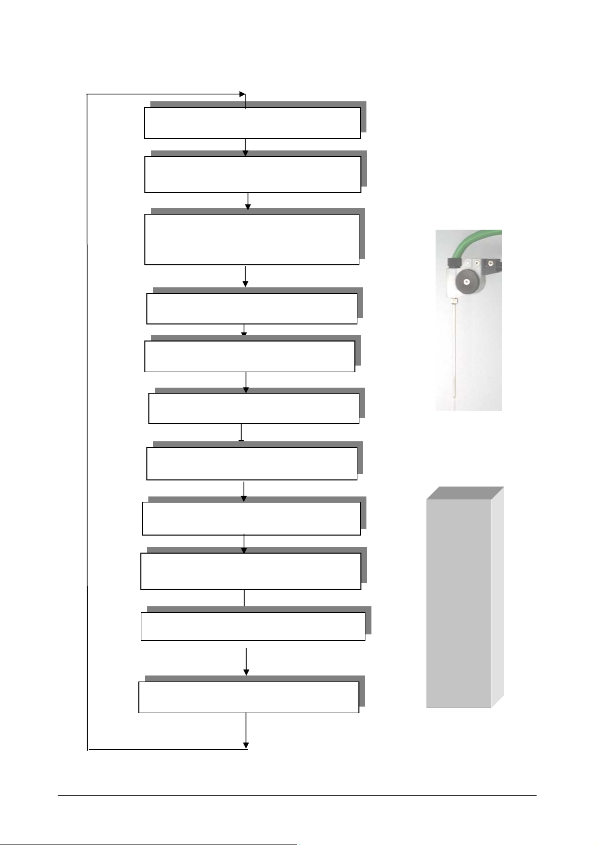
2.4.10 LEVEL SENSOR ASSY [P/N: 10-01478-00]
The level sensor assembly is composed by the level sensor board “A” (P/N:30-01392-00) and the
level sensor board “B” (P/N:30-01392-01).
The level sensor assembly, installed on the sampling probe head, is linked to the Arm interface
board. By a specific cable it transmits the relevant signal (the capacity variation produced by the
contact between the sampling probe and the liquid) to the Analytical Control Board.
Level sensor components and integrated circuits are mounted on the level sensor assembly.
Ellipse Service Manual Rev. 03 01 June 2009 Page 11
Page 26

Chapter 03 - INSTALLATION
CHAPTER 03 - INSTALLATION
INDEX
3.1 UNPACKING.........................................................................................................................2
3.2 INSTALLATION ...................................................................................................................4
3.2.1 INSTALLATION SITE SPECIFICATIONS ...................................................................... 4
3.2.2 ELECTRIC CURRENT REQUIREMENTS....................................................................... 4
3.2.3 CONNECTIONS TO ACCESSORIES ...............................................................................5
3.2.3.1 POWER SUPPLY/LINE INPUT...................................................................................... 5
3.2.3.2 CONNECTING THE INSTRUMENT TO THE COMPUTER .......................................6
3.2.4 ATTENTION....................................................................................................................... 6
3.2.5 SYMBOLS........................................................................................................................... 6
3.2.6 REGULATORY COMPLIANCE........................................................................................ 6
Ellipse Service Manual Rev. 03 01 June 2009 Page 1
Page 27
Chapter 03 - INSTALLATION
3.1 UNPACKING
The ELLIPSE is packed and delivered in two separate wooden crates: one contains the
analyzer itself and the other the computer, along with its accessories. In the event that the order
not include the PC component, packing and delivery will involve one wooden crate plus a
corrugated cardboard box. The packing has been expressly studied and designed to insure
maximum protection of the contents during shipping and handling. It is therefore extremely
important that the crate(s)/box be carefully examined upon delivery in order to ascertain their
integrity. Special attention should be dedicated to examining the color of the “Shock Watch”
glued to the crates, which must show the color ‘white’. A ‘red’ “Shock Watch” indicates that
the crate(s) have experienced some sort of ‘shock’ during handling, transport and/or delivery.
This fact must be noted by the courier on the delivery note, as must any and all visible external
damage (for example: holes, dents, rips or tears, water marks, etc.) evident at the moment of
delivery. This will simplify matters in the event of any future claims for damages.
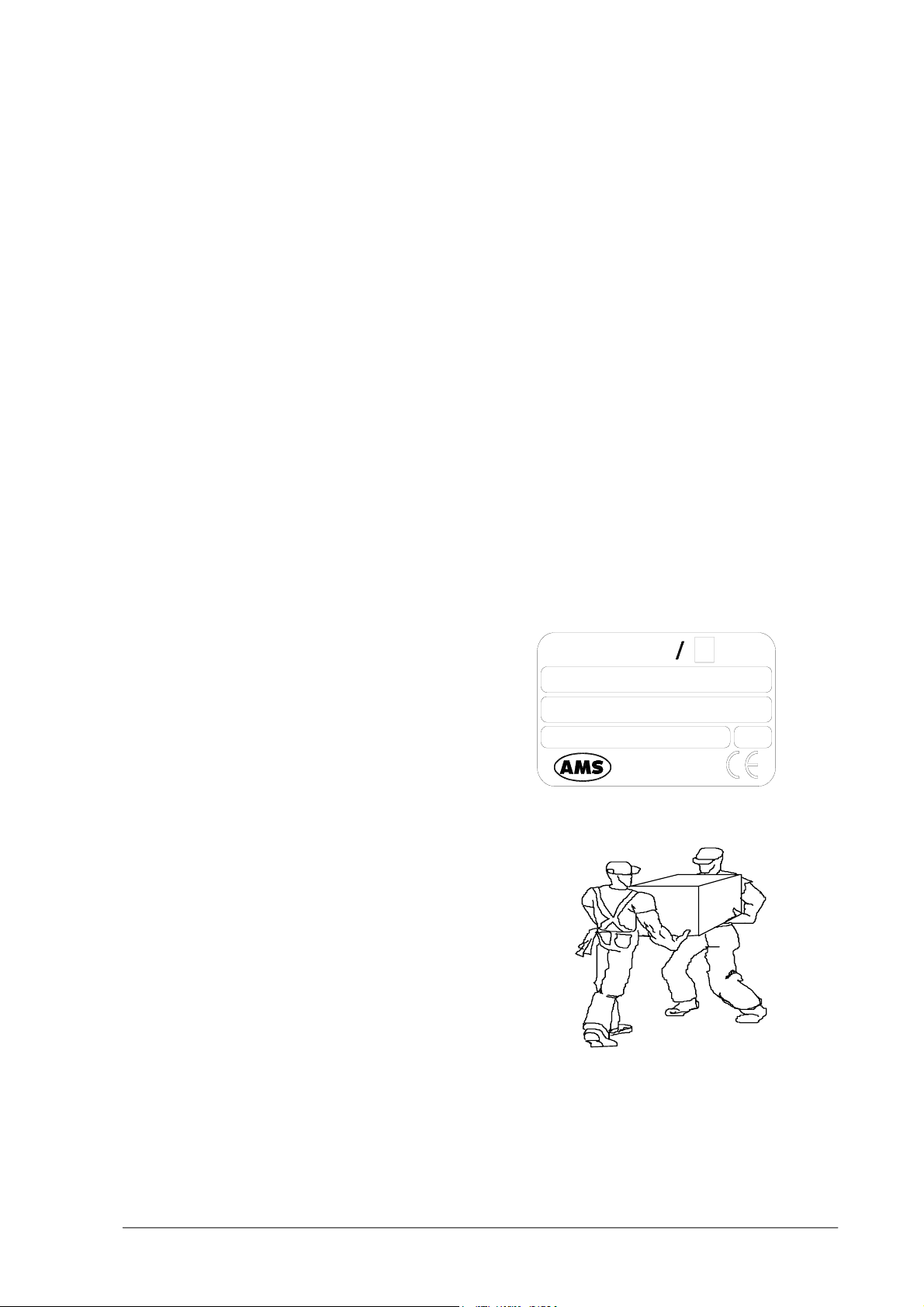
Upon arrival of the crate(s)/box, take out the
delivery note and make sure that all the items
on the packing list are included in the crates
and are undamaged. Make sure the series
number on the delivery note/packing list
corresponds to that impressed on the plate on
the right side of the instrument.
S/N
P/N
ELLIPSE
90 - 250Vac 47 - 63Hz
Analyzer
Medical
System
Rome-Italy
300W
Open the crate(s)/box from the top and very
carefully take out:
- the instrument;
- the computer and accessories.
MAKE SURE THAT THE UNPACKING IS CARRIED OUT BY TWO PEOPLE.
Ellipse Service Manual Rev. 03 01 June 2009 Page 2
Page 28

Chapter 03 - INSTALLATION
Do not discard the delivery crate(s)/box or the packing material until the correct functioning of
the instrument has been ascertained.
Remove all the items from the crate(s)/box very carefully.
Remove the adhesive tape from the cover of the samples and reagents housing, from the front
panels and from the samples and reagents racks.
Before connecting the "Ellipse", remove the protective packing material placed under the
sampling arm and under the wash station group.
Warning: in the event that it is necessary to repack any or all of the delivered item(s), the
following procedures must be carefully followed:
¾ Reposition the protective packing material under the sampling arm and under the wash
station group.
¾ Tape down (using masking tape if possible) the cover of the samples and reagents housing,
the front panels, and the samples and reagents racks.
¾ Remove the probe from the sampling arm and place it inside a cuvette. Then cap the
cuvette and tape the cap down.
¾ Be very careful to not bend the wash station cannulas when repositioning the protective
packing material.
¾ Fill the empty spaces around the accessories packed in the crate using “pluriballs” or other
suitable packing material.
Ellipse Service Manual Rev. 03 01 June 2009 Page 3
Page 29

Chapter 03 - INSTALLATION
3.2 INSTALLATION
The ELLIPSE must only be installed by a qualified technician who has been authorised and
trained to do so. During its installation the system will be checked once again to ensure correct
functioning. The persons who are required to operate the ELLIPSE system must have received
the adequate training. This should also include the "know-how" of the normal maintenance for
the instrument. A description of the maintenance will be found in Chapter 7 of this manual.
ELLIPSE is a complex system, and it is therefore extremely important that it is correctly
installed in order to fully guarantee fine performance. If the installation and use directions,
given in this manual, are not correctly followed and/or security indications are not respected,
AMS cannot guarantee correct functioning of the instrument. Apart from this, the security of
the operator could be placed at risk.
3.2.1 INSTALLATION SITE SPECIFICATIONS
Ascertain that the ELLIPSE system is not exposed to direct sunlight, draughts, dust or strong
magnetic fields. In addition, please take note of the following conditions required for the
location of the installation:
USE
DEGREE OF POLLUTION
INSULATION CLASS
INSTALLATION CATEGORY
TEMPERATURE
HUMIDITY
ALTITUDE
LOCATION
In covered and dry place
2
I
II
between18°- 30°C
20% ÷ 85%
Max 3000 m
Shelf or table with a minimum surface of 75 x 60 cm
stable and free of vibration
VENTILATION
Leave a minimum distance of 10 cm around the
instrument to permit air circulation . Make sure that
the front and rear holes are not blocked by any object
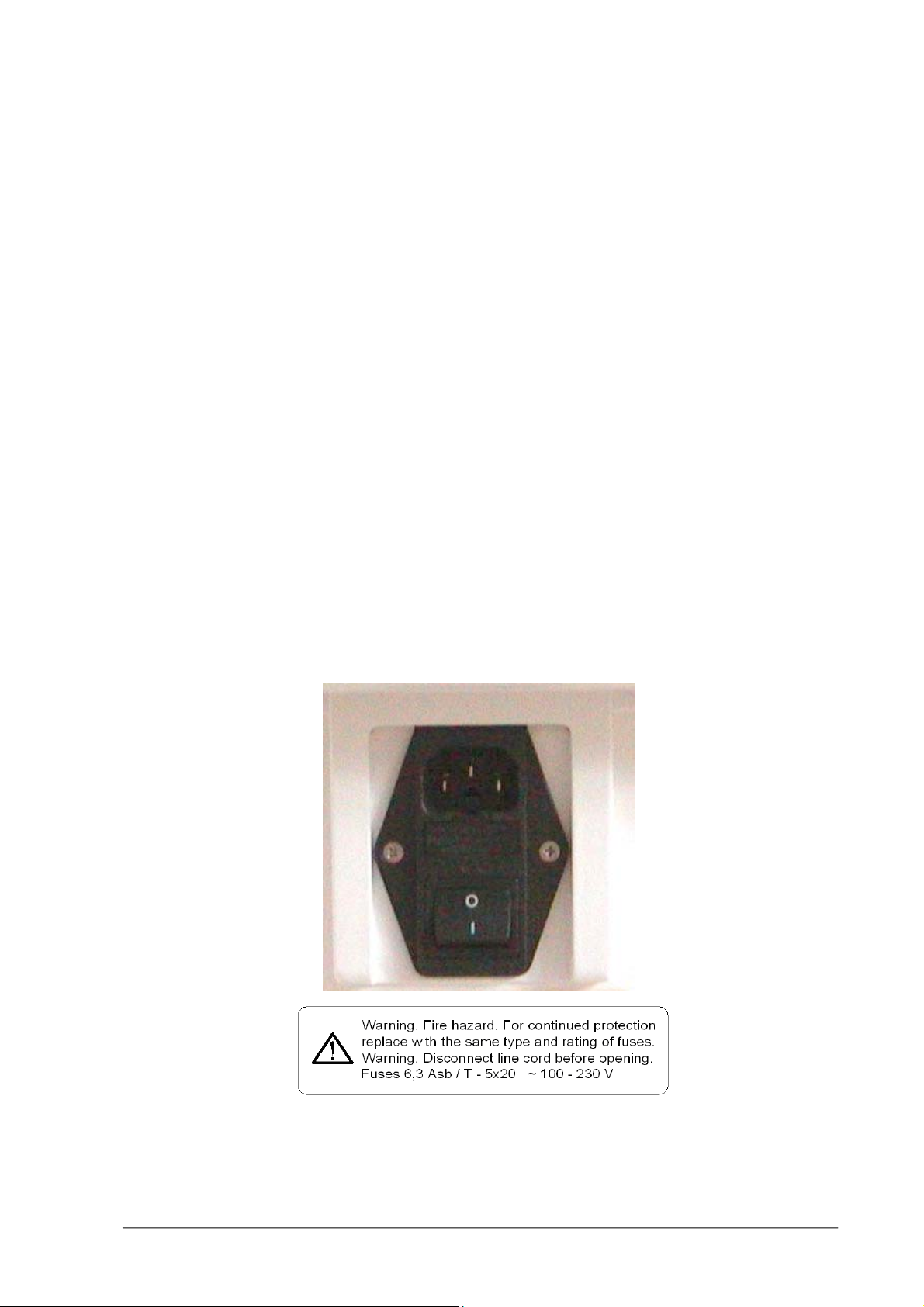
3.2.2 ELECTRIC CURRENT REQUIREMENTS
The power voltages to which the instrument is adapted are indicated on the left-hand side
(see fig. 1). It must be plugged into a plug of the correct voltage.
VOLTAGE
FUSES
100 ÷ 230 Vac 47/63 Hz ± 10%
6.3 Amp/T - 5 x 20
Ellipse Service Manual Rev. 03 01 June 2009 Page 4
Page 30
Chapter 03 - INSTALLATION
NOTE: IT IS ADVISABLE TO MAINTAIN THE MAXIMUM STABILITY OF THE ELECTRICAL CURRENT IN
THE LABORATORY
FOLLOWING SUPPLEMENTARY DEVICES IS RECOMMENDED
. WHERE THIS IS NOT POSSIBLE OR ASCERTAINABLE, USE OF THE
:
ELECTRONIC STABILIZER
Used to stabilise the electric voltage in the laboratory. Any stabiliser with a power
potential greater than 0.5 KW, currently available on the market, can be used.
NO-BREAK MODULE UPS - (Uninterrupted Power Supply)
This module provides two important functions:
- stabilises the main-line power
- supplies current to the instrument in case of a main-line power failure.
3.2.3 CONNECTION OF THE ACCESSORIES
3.2.3.1 POWER SUPPLY
Fig. 1 - – Plug (use the feeder cable supplied with the instrument).
The sticker indicates the power supply voltage and the values of the fuses.
Ellipse Service Manual Rev. 03 01 June 2009 Page 5
Page 31

Chapter 03 - INSTALLATION
3.2.3.2 COMPUTER - INSTRUMENT CONNECTION
The instrument and the Personal Computer are connected by one serial RS232 standard cable
(Cod. 9-35 0055.01), which provides the hardware support for the communication.
3.2.4 ATTENTION
The following label is found at the rear of the instrument.
NOTE: THE REAR PANELS OF THE INSTRUMENT MUST NEVER BE OPENED WITHOUT HAVING FIRST
SWITCHED THE INSTRUMENT OFF AND DISCONNECTED THE ELECTRICITY CABLE
.
THE MAINTENANCE AND CLEANING PROCEDURES FOUND IN CHAPTER 07 OF THIS
MANUAL MUST BE RESPECTED AT ALL TIMES
DECONTAMINATION PROCEDURE IN CASE OF INSTRUMENT REMOVAL
. REMEMBER TO FOLLOW THE
(SEE CHAPTER 07) .
3.2.5 SYMBOLS
ATTENTION: READ THE INSTRUCTIONS IN THE USER MANUAL
T
ERMINAL OF TOTAL MASS PROTECTION (CONDUCTOR)
REGULATORY COMPLIANCE
3.2.6
The ELLIPSE instrument complies with:
European Directive 98/79/CE for In vitro Diagnostics Devices
Ellipse Service Manual Rev. 03 01 June 2009 Page 6
Page 32

Chapter 04 – ELECTRICAL SCHEMES AND DRAWINGS
CHAPTER 04
- ELECTRICAL SCHEMES AND DRAWINGS -
INDEX
ELECTRONIC DIAGRAM ELLIPSE SC-16-00571-XX
HYDRAULIC DIAGRAM ELLIPSE SI-16-00571-XX
WIRING ME-50-01692-01
ANALYTICAL CONTROL BOARD SC02-30-01283-XX
ANALYTICAL CONTROL BOARD SE-30-01283-XX
STEPPER MOTORS DRIVER BOARD SC02-30-01284-01
STEPPER MOTORS DRIVER BOARD SE-30-01284-01
ARM INTERFACE BOARD (DX) SC02-30-01282-01
ARM INTERFACE BOARD (DX) SE-30-01282-01
PLATE INTERFACE BOARD (SX) SC02-30-01281-01
PLATE INTERFACE BOARD (SX) SE-30-01281-01
PRE-AMPL/ADC SE-30-00107-XX
PHOTOMETER LAMP BOARD SE-30-01576-00
LEVEL SENSOR ASSY SE-10-01478-00
ELECTROVALVES CONTROL BOARD SC-30-01626-00
ELECTROVALVES CONTROL BOARD SE-30-01626-00
CONTROL PANEL BOARD SE-30-01850-00
Ellipse Service Manual Rev. 03 01 June 2009 Page 1
Page 33

00012 Guidonia (Roma)
Drawn Checked
Approved
Date
Sheet
Doc.
P/N
Rev.
authorization will be prosecuted accordingly to the law.
L. Massenzi R. Cornacchia A. Gagliarducci
20/10/2005
1 of 1
SC
16
-
00571
-
XX
D
Rev. D
: emissione in riferimento
alla RMP n.268
(optional)
(Reference Channel)
18,300)
(optional)
Via E. Barsanti, 17/A
(Via Tiburtina Km
BarCode Reader
Electronic Diagram Ellipse
The present document is property of AMS, any use without
Description
30-01283-..
Analytical Control Board
(Sample Channel)
Pre-Ampl/ADC
Pre-Ampl/ADC
Page 34

Page 35

Page 36

00012 Guidonia (Roma)
Drawn Checked
Approved
Date
Sheet
Doc.
P/N
Rev.
authorization will be prosecuted accordingly to the law.
L. Massenzi R. Cornacchia A. Gagliarducci
20/10/2005
1 of 1
Analytical Control Board
30
-
01283
-
XX
A
30
-
01283
-
..
18,300)
(Sample Channel)
Pre-Ampl/ADC
(Reference Channel)
Pre-Ampl/ADC
Via E. Barsanti, 17/A
(Via Tiburtina Km
SC02
Rev. A: emissione in riferimento alla RMP n.268
The present document is property of AMS, any use without
Description
50-01692-01
ISE Module
Page 37

1
OPTOCU
OPTOCA
OPTORE
OPTOWH
WASTE1
WASTE2
LIQUID1
LIQUID2
LIQUID3
LEAKPI
RISCPI
uPSCAMB
VMVM
J20 H2X12
2
3
3V3
R2 220C6
4
X1
6,144 Mhz
10uF/25V
+
C12
3V3
5
LD1086V3.3
VM
VB
OPTOBH
OPTOBV
OPTODO
OPTOPP
PR
PG
PV
DEPR
uPACIDB
uPDOS
EVDOS
LAMPV
LAMPR
LAMPG
EV3PP
23
24
24
DIRRE
DIRCU
DIRCA
256
1Q2Q3Q
1D2D3D
347
DB0
DB1
DB2
uP1H2OPE0
uPBAND
uP2H2O
18
1Y3
1Y2
1Y1
1A3
1A2
1A1
2
PE2
PE1
0.1uF
EXTAL
C47
C46
R3 0R
XTAL
Rx1=470
se
TP1
123
IN
OUT
GND
VL
+
470uF/50V
C49
H17X2
J9
12
34
56
78
910
J8
12
34
56
78
910
uP1H2O
EV1H2O
uPBASICP
11131517192123
uP2H2O
EV2H2O
EV2PP EV1PP
uPBAND
DIRWH
DIRFO
DIRBV
DIRBH
9
1213
1617
7Q7D
5Q5D
4Q
4D
6D 6Q
8
14 15
DB3
DB4
DB5
DB6
RISCPI
CTRLAMPPE5
uPBASICP
uPSCAMB
2Y3
2Y2
2Y1
1Y4
2A3
2A2
2A1
1A4
864
11
PE3
PE6
PE4
C60 0.1uF
C5 470pF
15pF
PVCC
15pF
X1<5Mhz
1
TP-GND
C11
0.1uF
PVCC
U2
U3
6
5
4
3
2
1
1112
1314
1516
1718
1920
2122
2324
2526
2728
2930
3132
3334
1112
1314
1516
1718
1920
2122
2324
2526
SWCOP
WASTE1WASTE2
8
10121416182022
LEAKWH
DIRDO
8D 8Q
18 19
DB7
BUZZER
3579121416
20
2Y4
2A4
1
171513
PE7
R1
3V3
C7
C8
AVCC
OUT
J6 MOLEX
SLI
ARMSW
CTR1
CTR2
WDT
DACB
RISAB
TB
TA
SB
LEAKB
PWMB
EV3PP
INPUTB
H13X2
LIQUID1LIQUID2
LIQUID3
13579111315171921
13579
246810121416182022
246
LIQUID4
PVCC
1011
20
VCC
GNDCLK
ENG
U10 74HC377
1
WRL
PC1
PVCC
74HC244U15
VCC
C39 0.1uF
1OE
2OE GND
19 10
P35
P36
P37
3K3
0.1uF
3V3
0.1uF
C9
0.1uF
+
C10
10uF/25V
VB
C50
123
LM2575
IN
GND
LM7805CT
VM
D D
CTRLAMP
BUZZER
TFOPTOFO
TP
SP
LIQUID4
DACP
INPUT
WDT
OPTOWH2
CTR2
12345
EVACIDP
EVBASICP
C40 0.1uF
PVCC
PVCC
PG0
PG1
PG2
(CS2)
PG3
(CS1)
PG4
WDTOVF
RES
NMI
STBY
FWE
XTAL
EXTAL
OSC1
PF7
PF6
PF5
PF4
PF3
PF2
PF1
PF0
0.1uF
12345
470uF/50V
P96
DACB
J17
J21
uPACIDP
U1
65
66
67
68
69
70
71
72
73
74
75
76
77
78
79
80
81
82
83
84
85
86
87
88
89
90
91
92
93
94
95
96
97
98
99
100
101
102
D3
+
C15
H3
123
R52 1K
+
RISAB
P96
J16
H6
6
PVCC
VM
C45
0.1uF
AVCC
C4
0.1uF
P33
P34
63
64103
P33/TXD1/SCL1
P34/RXD1/SDA0AN0/P40
NC
NC
PLLVCC
PLLCAP
PLLVSS
RES
NMI
STBY
FWE
XTAL
VCC
EXTAL
VSS
OSC1
OSC2
PVCC1
PF7/CLK
VSS
PF5/RD
NC
NC
AVCC
VREF
AN1/P41
104
105
P40
P41
P42
U4
1N5818
L1
470uH
TX4
C55
H3
123
R49 1K R51 1K
P90 P91 P92
R50 1K
TA TB SB
P32
VSS
P32/SCK0/SDA1/IRQ4
P36/RXD4
P37/TXD4
PG2/CS2
PG3/CS1
PG4/CS0
WDTOVF
PF6/AS/LCAS
PF4/HWR
AN3/P43
AN2/P42
106
107
P43
P44
PVCC
RX4
1uF/50
+
C54
1uF/50
+
C53
1uF/50
+
C52
1uF/50
PVCC
P31
PD5
P30
PD6
PD7
5859606261
PVCC2
PD6/D14
PD7/D15
P30/TXD0/IRTXD
P31/RXD0/IRRXD
PG0/CAS/IRQ6
PG1/CS3/OE/IRQ7
PF3/LWR/ADTRG/IRQ3
PF2/LCAS/WAIT/BREQ0
PF1/BACK/BUZZ
PF0/BREQ/IRQ2
AN8/P90
DA1/AN7/P47
DA0/AN6/P46
AN5/P45
AN4/P44
108
109
110
111
112
P45
P46
P47
P90
P91
C13
+
470uF/50V
C14
0.1uF
5
VB
4
3
2
1
VM
P97
DACP
H3
123
J15
+
P97
DACP
J14
123
0.1uF
C44
AVCC
PVCC
0.1uF
PD2
PD0
PD1
PD4
PD3
PD3/D11
PD4/D12
PD5/D13
P35/SCK1/SCK4/SCL0/IRQ5
AN11/P93
AN10/P92
AN9/P91
113
114
115
P92
P93
P94
ISE - NO3
Module
J4 H5
PE7
PE6
51525354555657
49
50
VSS
PVCC1
PE7/D7
PD1/D9
PD0/D8
PD2/D10
DA2/AN14/P96
DA3/AN15/P97
AN13/P95
AVSS
AN12/P94
P95
CLKCU
PB0
CS4/DREQ0/TMCI011/TMRI01P70
116
117
118
119
120
121
P70
P71
P96
P97
EV2PP
CLKCA
EV1PP
EV1H2O
EV3PP
18
2Y1
1Y4
1Y3
1Y2
1Y1
2A1
1A4
1A3
1A2
1A1
864
2
11
PB1
PB3
PB2
PB5
PB4
C59
H3
R47 1KR45 1K R48 1K
SPTP
P93 P94 P95
R46 1K
TF
C3
PE5
PE4
PE5/D5
PE6/D6
SYNCI/CS6/TEND0/TMO0/P72
CS5/DREQ1/TMCI23/TMRI23/P71
122
123
P72
P73
CLKRE
EV2H2O
3579121416
2Y3
2Y2
2A3
2A2
171513
PB7
PB6
1uF/50
+
C58
1uF/50
+
C57
1uF/50
+
C56
1uF/50
PE0
PE1
PE2
PE3
P17
C51 0.1uF
H8S/2633F
39
404142434445464748
PE0/D0
PE1/D1
PE2/D2
PE3/D3
PE4/D4
P17/TIOCB2/TCKLD/PWM3
CS7/TEND1/TMO1/P73
MRES/TMO2/P74
SCK3/TMO3/P75
RXD3/P76
MD0
TXD3/P77
124
125
126
127
128
P74
P76
P75
P77
C32
0.1uF
PVCC
PVCC
20
2Y4
VCC
1OE
2A4
2OE GND
1
19 10
C C
CLKBH
18
74HC244U13
2
P10
(RD)(HWR)
PF5
PD4
PC4
PC3
CTR2
25
PC1
PC0
PC2
PF4
R41 10K
P73
C
RR4
C
RR3
P14 PE4
C
RR2
PB4
C
RR1
DB0
PVCC
181716151413121120
2345678
PD0
IRQ1/PWM2/TIOCA2/PO14/P16
38
TCKLC/TIOCB1/PO13/P15
37
NC
36
NC
35
IRQ0/TIOCA1/PO12/P14
34
A23/TCKLB/TIOCD0/PO11/P13
33
A22/TCKLA/TIOCC0/PO10/P12
32
A21/DACK1/TIOCB0/PO9/P11
31
A20/DACK0/TIOCA0/PO8/P10
30
VSS
29
SCK2/A19/PA3
28
RXD2/A18/PA2
27
TXD2/A17/PA1
26
A16/PA0
25
TIOCB5/A15/PB7
24
TIOCA5/A14/PB6
23
TIOCB4/A13/PB5
22
TIOCA4/A12/PB4
21
TIOCD3/A11/PB3
20
TIOCC3/A10/PB2
19
TIOCB3/A9/PB1
18
PVCC1
17
TIOCA3/A8/PB0
16
VSS
15
PWM1/A7/PC7
14
PWM0/A6/PC6
13
A5/PC5
12
VCC
11
A4/PC4
10
VSS
9
A3/PC3
8
A2/PC2
7
A1/PC1
6
A0/PC0
5
NC
4
NC
3
MD2
2
MD1
1
PVCC
EVACIDP
CLKBV
EVDOS
uPDOS
EVBASICP
2Y1
1Y4
1Y3
1Y2
1Y1
2A1
1A4
1A3
1A2
1A1
864
11
P12
P15
P13
P11
P14
RES
PD5
PD2
PD3
R42 10K
PE3
PE5
P13
P15
PB3
PB5
DB1
DB2
B1B2B3B4B5B6B7
A1A2A3A4A5A6A7A8G
PD2
PD1
P16
P15
P14
P13
P12
P11
P10
PA3
PA2
PA1
PA0
PB7
PB6
PB5
PB4
PB3
PB2
PB1
PB0
PC7
PC6
PC5
PC4
PC3
PC2
PC1
PC0
MD2
PVCC
CLKDO
uPACIDP
3579121416
2Y3
2Y2
2A3
2A2
171513
P17
P16
RX2
RTS
PD6
PD0 PD7
PD1
PF3
PE6
PE2
P12
P16
PB6
PB2
DB3
DB4
PD3
PD4
PVCC
C2
C1
J19
PVCC
PVCC
20
2Y4
VCC
1OE
2A4
1
19 10
3V3
11131517192123
8
101214161820222426
(CS2)
TX2
DTR#
PG2
P35
1
2
J22
DSYNC
CTR2
12
C+8 10K
3456789
PE1
PE7
PE0
12
C+8 10K
3456789
P11
P17
12
C+8 10K
3456789
PB7
PB1
PB0 P10
19
C+8 10K
8765432
DB6
DB5
DB7
B8
9191
PG3
PD5
PD7
PD6
STBY
NMI
R35 10K
R36 10K
0.1uF
PVCC
0.1uF
3V3
R40
10K
1
2
H2
C33
0.1uF
74HC244U14
2OE GND
135791113151719212325
246
PVCC
13579
2468101214161820222426
H2
PVCC
PVCC
10
VCC
PF5
PA3
R37 10K
PWDCA
256
347
DB0
J5 H13X2
DSYNC ADC
GND
DIR
U25 74HC245
PVCC
P70
P71
18
1Y1
1A1
2
INPUTB
INPUT
PC5
18
1Y1
1A1
2
DRDYAUX P32
DINDA
PWDRE
PWDCU
1Q2Q3Q
1D2D3D
DB1
DB2
CLK
G0AUX
DRDYAUX
97531
97531
108642
864
10
SCLK
DINAUX
-VB
LAMPG
LAMPV
256
1Q2Q3Q
1D2D3D
347
DB0
DB1
DB0
DB1
18
1Y1
1A1
2
P41
P40
18
1Y1
1A1
2
OPTOCA
OPTOCU
C34
CLKPP
PWMB
CLKFO
1Y4
1Y3
1Y2
1A4
1A3
1A2
864
11
P74
P73
P72
PC6
PC7
PG4
1Y4
1Y3
1Y2
1A4
1A3
1A2
864
11
DINRF
DINAUX
OPTOPP
PWDFO
PWDWH
PWDBH
9
1213
5Q5D
4Q
4D
8
14 15
DB3
DB4
DB5
CLK
G0R
G1AUX
J12 H5x2
2
DSYNC
VB
ENADO
LEDV
LEDR
LAMPR
9
1213
5Q5D
4Q
4D
8
14 15
DB5
DB4
DB3
DB2
C37
PVCC
DB2
DB3
DB4
DB5
2Y1
1Y4
1Y3
1Y2
2A1
1A4
1A3
1A2
864
11
PRPVPG
SLI
ARMSW
LEAKPI
P45
P44OPTOWH
P43
P42
2Y1
1Y4
1Y3
1Y2
2A1
1A4
1A3
1A2
864
11
OPTOBH
OPTORE
OPTOFO
0.1uF
ENAPIP77
CLKWH
ENABVWH
3579121416
20
2Y4
2Y3
2Y2
2Y1
2A4
2A3
2A2
2A1
1
171513
P76
P75
PVCC
PG0
PG1
WDT
3579121416
20
2Y4
2Y3
2Y2
2Y1
2A4
2A3
2A2
2A1
1
171513
DRDYDA
WDTOVF
DRDYRF
PVCC
PWDBV
PWDDO
1011
1617
7Q7D
6D 6Q
8D 8Q
18 19
WRL
DB6
DB7
B B
DRDYRF
97531
10
SCLK
PVCC
ENAPP
CTR1
1617
7Q7D
6D 6Q
18 19
DB6
DB7
0.1uF
DB6
DB7
3579121416
2Y3
2Y2
2A3
2A2
171513
SWCOP
ALLVENT
P47
P46
3579121416
2Y3
2Y2
2A3
2A2
171513
OPTODO
OPTOBV
PVCC
VCC
1OE
2OE GND
19 10
C36
PVCC
VCC
1OE
2OE GND
19 10
C35
PVCC
20
VCC
GNDCLK
ENG
1
PC0
G1R
97531
108642
864
DSYNC
DINRF
-VB
C41
0.1uF
PVCC
1011
20
VCC
GNDCLK
ENG
8D 8Q
1
PC3
WRL
R44 10K
PVCC
20
2Y4
VCC
1OE
2A4
2OE GND
1
19 10
ENA0
C38
PVCC
PVCC
20
2Y4
VCC
1OE
2A4
2OE GND
1
19 10
123
NME1212S
74HC244U23
0.1uF
R4 3K3
74HC244U17
D1
0.1uF
U9 74HC377
Refer to the Serigrafy
2
PF0
74HC244U19
74HC244U16
VB
1 2
RTS
CLK
G0D
G1D
DRDYDA
97531
97531
108642
J11 H5x2
864
10
SCLK
DINDA
VB
PVCC
DB0
DB1
18
1Y1
U12 74HC377
1A1
2
WASTE1
WASTE2
LOCK
uPACIDB
CTR2
PF2
18
1Y3
1Y2
1Y1
1A3
1A2
1A1
864
2
PF0
PF1
PF3
LIQUID4
0.1uF
G1R
G0R
G1D
G0D
256
9
1Q2Q3Q
1D2D3D
347
8
DB0
DB1
DB2
DB3
4
U5
0.1uF
C16
+
-VB
C18
+
10uF/25V
C17
10uF/25V
D5
4V7
R5
3K3
1N4148
PVCC
R43 10K
DTR#
PWDCA
PWDBH
ENAPI
ENABHFO
PWDFO
33343536373839404142434445464748495051525354555657585960616263
B1B2B3B4B5B6B7B8B9
A1A2A3A4A5A6A7A8A9
123456789
DIRFO
DIRCA
CLKFO
CLKBH
CLKCA
J10 H5x2
2
DSYNC
VB
-VB
C48
0.1uF
DB2
DB3
DB4
DB5
DB6
2Y2
2Y1
1Y4
1Y3
1Y2
2A2
2A1
1A4
1A3
1A2
864
11
LEAKB
LEAKWH
LIQUID3
LIQUID2
LIQUID1
SCLK
ENABHFO
P35B
3579121416
20
2Y4
2Y3
2Y2
2Y1
1Y4
2A4
2A3
2A2
2A1
1A4
1
171513
11
OPTOWH2 PF7
P77
PA0
P35
DIRPP
PWDPP
G1AUX
G0AUX
1213
1617
7Q7D
5Q5D
4Q
8D 8Q
4D
6D 6Q
14 15
18 19
DB4
DB5
DB6
DB7
MD2
RES
FWEBOOT
121314151617181920
F0F1F2F3F4F5F6
U24 16V8
I0I1I2I3I4I5I6I7I8
123456789
LOCK_IN
RESB
R6 3K3
D2
1 2
DTR
ENABHFO
1011121314151617181920212223242526272829303132
DIRBH
DB7RESA
PVCC
3579121416
20
74HC244U20
2Y4
2Y3
VCC
1OE
2A4
2A3
2OE GND
1
171513
19 10
ENA1ENA1
DEPR
C43
0.1uF
PVCC
PVCC
PVCC
74HC244U18
VCC
LD1
PVCC
U11 74HC377
ENA0
(/CS1)
PG3
4V7
PWDCU
B13
A13
CLKCU
J18
LOCK_IN
DTR#
F7
(/RD)
(/HWR)
PF4
123
RESA
PWDWH
B14
B15
A14
A15
CLKWH
LED RED
R33 4K7
LEDR
C42
0.1uF
LOCKED(ON)
1
LOCK
PVCC
10
VCC
GND
I9
11
PF5
DS1233-10
PVCC
ENABVWH
PWDBV
ENAPI
B16
B17
A16
A17
CLKBV
DIRWH
DIRCU
1OE
2OE GND
19 10
PVCC
1011
20
VCC
GNDCLK
ENG
1
PC2
WRL
FWE
WRL
PA3
PC0
D6
R7
3K3
1N4148
U6
B10
B11
B12
A10
A11
A12
Approved
L.M. 10/09/2004
A.G. 10/09/2004
R.CORNACCHIA
CheckedDescription
Drawn
Checked
Approved
RMP 224
0
PVCC
R38
PVCC
LD2
LED GREEN
R34 4K7
LEDV
PVCC
2
H2
C310.1uF
R39 10K
C19 0.1uF
PVCC
PVCC
C26
ENABVWH
B18
B19
B20
B21
A18
A19
A20
A21
DIRBV
A A
Rev.
10K
C30
U8 MAX202
C25
0.1uF
U7 MAX202
B22
B23
A22
A23
RES
DTR
RTS
Serial IN
RS232
RX2
TX2
ALLVENT
VB
PVCC
TX0 RX0
RX1TX1
VM
0.1uFC270.1uF
TX1
RX1
VCCC1+
GND
T1OUT
V+
C1-
2345678 9
C28
0.1uF
RX0
VCCC1+
GND
T1OUT
V+
C1-
2345678 9
C22
0.1uF
C23
PWDRE
PWDPP
B24
B25
B26
B27
A24
A25
A26
A27
CLKRE
CLKPP
Electronic
R1IN
C2+
R1IN
C2+
B28
A28
0
1 1
1
SE-30-01283-XX
Analytical Control Board
Title
Housing Fan
P34
P33
R1OUT
C2-
0.1uF
R8
0R
P31
P30
R1OUT
C2-
0.1uF
ENAPI
PWDDO
B29
A29
CLKDO
DIRRE
10/09/2004
A3
Size Document Number Rev
Date: Sheet of
5
4
3
2
1
J1 H5
3
2
1
8
7
6
5
4
3
2
1
P37
101112131415161
T1IN
V-
TX4
C29
PA1
101112131415161
T1IN
V-
TX2
C24
ENAPP
B30
A30
DIRPP
2
J13 H3
BarCode
J2 H8
4
3
2
1
J3 H4
Diagnostic
P36
3
T2IN
R2IN R2OUT
T2OUT
RX4
0.1uF
TX0
PA2
4
T2IN
R2IN R2OUT
T2OUT
RX2
0.1uF
5
ENADO
64
B31
B32
A31
A32
J7 DIN 64_AB-H
DIRDO
Page 38

00012 Guidonia (Roma)
Drawn Checked
Approved
Date
Sheet
Doc.
P/N
Rev.
authorization will be prosecuted accordingly to the law.
L. Massenzi R. Cornacchia A. Gagliarducci
20/10/2005
1 of 1
30
-
01284
-
01
A
Rev. A
18,300)
Via E. Barsanti, 17/A
(Via Tiburtina Km
: emissione in riferimento alla RMP n.268
30-01283-..
The present document is property of AMS, any use without
SC02
Stepper Motors Driver Board
Description
J7
U5
50-01692-01
Page 39

0
H8X2
J3
1
2
1
DOB
DOA
PPB
PPA
BVB
BVA
BHB
1
BHA
3
3
5
5
7
7
9
9
11
1314
1516
11
1314
1516
2
4
6
8
10
12
DOBN
4
DOAN
6
PPBN
8
PPAN
10
BVBN
12
BVAN
BHBN
BHAN
BHB
BHAN
BHBN
BHA
PWDCA
PWDBH
ENACA
ENAFO
ENABH
PWDFO
33343536373839404142434445464748495051525354555657585960616263
B1B2B3B4B5B6B7B8B9
A1A2A3A4A5A6A7A8A9
123456789
DIRCA
CLKFO
DIRFO
CLKBH
CLKCA
R6
1R-2W
B10
A10
1011121314151617181920212223242526272829303132
DIRBH
PWDWH
PWDCU
ENAWH
PWDBV
ENACU
ENABV
B11
B12
B13
B14
B15
B16
B17
B18
B19
B20
B21
B22
B23
B24
A11
A12
A13
A14
A15
A16
A17
A18
A19
A20
A21
A22
A23
A24
CLKCU
BVA
DIRBV
CLKBV
DIRWH
CLKWH
DIRCU
BVB
BVBN
BVAN
RESMOT
R12
ENARE
PWDRE
B25
B26
A25
A26
CLKRE
1R-2W
ENADO
PWDPP
ENAPP
PWDDO
64
B27
B28
B29
B30
B31
B32
A27
A28
A29
A30
A31
A32
J1 DIN 64_AB-H
DIRDO
CLKDO
DIRRE
DIRPP
CLKPP
DOB
R18
1R-2W
Approved
CheckedDescription
A.G. 10/09/2004
L.M. 10/09/2004
Approved
R.CORNACCHIA
Drawn
Checked
1 1
1
SE-30-01284-01
WHB
WHA
FOB
FOA
REA
CUB
CUA
CAB
CAA
2
12
34
56
78
910
1112
1314
1516
1718
1920
J2 H10X2
WHBN
WHAN
FOBN
FOAN
REBN REB
REAN
CUBN
CUAN
CABN
CAAN
C15
0.1uF
VM
+
C3100uF/50
D10
D9
24
231915
VMA
VMB
VCC
13
C14
0.1uF
CK1
72635108
RESMOT
PVCC
D11
20
FA1
FB1
FA2
RES
CK2ENDIRPDM1
CLKBH
DIRBH
D12
162118
FB2
4
PWDBH
1R-2W
R5
D22
D23
20
FA1
FB1
FA2
RES
CK2ENDIRPDM1
DIRBV
CLKBV
D24
162118
FB2
4
PWDBV
C21
VM
17
SA
SB
GNDPB
SDIC403
M2
GNDD GNDPA
OSC
9
SWBH0
SWBH1
C30
3n3
U3
1 22
D21
0.1uF
24
VMA
VMB
VCC
72635108
13
C20
0.1uF
231915
CK1
RESMOT
+
C6100uF/50
PVCC
1R-2W
R11
17
SA
SB
GNDD GNDPA
M2
OSC
9
1 22
SWBV1
SWBV0
C33
3n3
C27
VM
GNDPB
SDIC403
U6
D33C26
PVCCPVCC
D34
24
231915
VMA
VMB
VCC
CK1
72635108
13
RESMOT
0.1uF
0.1uF
+
C9100uF/50
D35
20
FA1
FB1
FA2
RES
CK2ENDIRPDM1
CLKDO
DIRDO
D36
162118
FB2
4
PWDDO
1R-2W
R17
17
SA
SB
GNDPB
SDIC403
GNDD GNDPA
M2
OSC
9
SWDO1
SWDO0
C36
3n3
U9
1 22
RMP 224
0
Rev.
SWBH0
SWBH1
4
3
SW3
1
2
SWBV0
SWBV1
4
3
SW6
SW DIP-2
1
2
SW DIP-2
Stepper Motors Driver Board
Title
SWDO0
4
SW9
1
10/09/2004
A3
Size Document Number Rev
Date: Sheet of
SWDO1
3
2
SW DIP-2
2
ENABH
FOBN
FOA
FOAN
D5
D6
24
VMA
VMB
VCC
72635108
13
C12
0.1uF
FOB
231915
20
FA1
FA2
CK1
RES
CK2ENDIRPDM1
CLKFO
RESMOT
D7
162118
FB1
PWDFO
DIRFO
R4
1R-2W
1R-2W
R3
D8
SA
SB
FB2
M2
OSC
9
4
SWFO0
SWFO1
C29
3n3
C19
0.1uF
VM
17
C5100uF/50
GNDPB
SDIC403
GNDD GNDPA
U2
1 22
1
TP1
VMVB
3
VL
PVCC
VB
TP-GND
6
5
4
3
2
1
J4 MOLEX
C40
0.1uF
C39
+
470uF/50
C38
0.1uF
C13
0.1uF
VM
+
C2100uF/50
PVCC
WHA
D17
24
+
VMA
VCC
PVCC
13
C18
0.1uF
ENABV
WHB
WHAN
WHBN
D18
D19
231915
20
162118
FA2
FB1
FA1
VMB
CK1
RES
CK2ENDIRPDM1
72635108
DIRWH
PWDWH
CLKWH
RESMOT
R10
1R-2W
1R-2W
R9
D20
17
SA
SB
FB2
GNDPB
GNDD GNDPA
OSC
M2
9
4
1 22
SWWH1
SWWH0
C32
3n3
C25
VM
SDIC403
U5
D29
0.1uF
24
+
C8100uF/50
13
C24
0.1uF
ENADO
PPB
PPBN DOBN
PPA DOA
PPAN DOAN
D31
D30
231915
20
FA2
FA1
VMB
VMA
VCC
CK1
RES
CK2ENDIRPDM1
72635108
CLKPP
RESMOT
162118
FB1
DIRPP
PWDPP
1
C+9 10K
2345678
R16
1R-2W
1R-2W
R15
D32
17
SA
SB
FB2
GNDPB
SDIC403
SW2
GNDD GNDPA
OSC
M2
9
4
SWPP0
SWPP1
C35
3n3
U8
1 22
SWWH1
SWPP1
SWPP0
SWBH1
SWBH0
SWBV1
SWWH0
SWFO1
SWFO0
4
3
1
2
SWWH1
4
3
SW5
SW DIP-2
SW DIP-2
1
2
RR2
9
10
SWDO1
SWBV0
SWDO0
3
SWPP0
SWPP1
4
3
SW8
SW DIP-2
1
2
C37
+
470uF/50
4
5
123
IN
OUT
GND
LM2940C
U10
C11
0.1uF
VM
C1100uF/50
R19
10K
RESMOT
PVCC
CAA
D1
24
+
VMA
VCC
PVCC
13
C10
0.1uF
ENAFO
CAB
CABN
CAAN
D2
D3
231915
20
162118
FA1
FB1
FA2
VMB
CK1
RES
CK2ENDIRPDM1
72635108
CLKCA
DIRCA
PWDCA
RESMOT
ENACA
ENAWH
CUB
CUAN
CUA
D14
24
231915
FA1
VMA
VMB
VCC
CK1
RES
72635108
13
RESMOT
0.1uF
CUBN
D15
20
162118
FB1
FA2
FB2
CK2ENDIRPDM1
CLKCU
PWDCU
DIRCU
ENACU
R8
1R-2W
1R-2W
R7
D16
17
SA
SB
GNDPB
GNDD GNDPA
M2
OSC
9
4
1 22
SWCU1
SWCU0
C31
3n3
C23
0.1uF
VM
C7100uF/50
SDIC403
U4
R2
1R-2W
1R-2W
R1
D4
SA
SB
FB2
M2
OSC
9
4
1 22
SWCA0
SWCA1
C28
3n3
C17
VM
17
GNDPB
SDIC403
GNDD GNDPA
U1
D13
0.1uF
+
C4100uF/50
PVCC
C16
REA
D25
24
+
VMA
VCC
PVCC
13
C22
0.1uF
ENAPP
REBN
REAN
REB
D27
D26
231915
20
FA1
FB1
FA2
VMB
CK1
RES
CK2ENDIRPDM1
72635108
PWDRE
RESMOT
CLKRE
DIRRE
ENARE
D28
162118
FB2
OSC
4
SWRE0
C34
1
PVCC PVCC
C+9 10K
2345678
R14
1R-2W
1R-2W
R13
17
SA
SB
GNDPB
GNDD GNDPA
M2
9
1 22
SWRE1
3n3
SWCA0
SWCA1
4
3
SDIC403
SW1
1
2
U7
SWCA1
SWCU0
SWCU1
SWCU0
4
SW4
SW DIP-2
1
9
10
SWCA0
SWCU1
3
2
SWWH0
SWFO0
SWRE1
SWRE0
SWFO1
SWRE0
SWRE1
4
3
SW7
SW DIP-2
1
2
4
RR1
SW DIP-2
5
D D
C C
B B
A A
Page 40

00012 Guidonia (Roma)
Drawn Checked
Approved
Date
Sheet
Doc.
P/N
Rev.
authorization will be prosecuted accordingly to the law.
L. Massenzi R. Cornacchia A. Gagliarducci
20/10/2005
1 of 1
Arm Interface Board (Dx)
30
-
01282
-
01
B
05
-
017
00
-
20
18,300)
Via E. Barsanti, 17/A
(Via Tiburtina Km
SC02
50-01692-01
Rev. B: emissione in riferimento alla RMP n.268
The present document is property of AMS, any use without
Description
50-01867-00
30-01283-..
Analytical Control Board
Page 41

0
VM
VB
VL
VM
D-LAMPG
15
4
LAMPG
D-uPDOSBVBN
14
O4
O5
I5I6I7
I4
567
uPDOS
D-RISOUTB
D-EVDOS
SLI
ARMSW
CTR1
12
10
13
O6
O7
COM
ULN2803
I8 O8
GND
9
8 11
EVDOS
RISOUTB
(EV3PP)
CTR2
1 2
3 4
5 6
J25
OPTOPP
OPTODO
OPTOBH
OPTOBV
TB
SB
WDT
7 8
PR
TA
DACB
RISAB
9 10
11 12
13 14
15 16
17 18
19 20
DEPR
PV
uPDOS
uPACIDB
PG
RISOUTB
INPUTB
PWMBLAMPV
LEAKB
21 22
23 24
25 26
27 28
29 30
31 32
33 34
H17X2
LAMPR
LAMPG
EVDOS
J21
VM
12345
C11
+
6
MOLEX
100uF/50V
1
TP-GND
TP1
D-LAMPV
D-LAMPR
D-uPACIDBuPACIDB
181716
O1O2O3
U1
1
I1I2I3
123
LAMPR
LAMPV
J24H9123456789
VM
D-RISOUTB
INPUTB
RISANB
RISAB
RISOUTB
WDT
TB
Spare
Approved
CheckedDescription
A.G. 10/09/2004
L.M. 10/09/2004
Approved
R.CORNACCHIA
Drawn
Checked
1 1
1
1
U4A
C8
0.1uF
84
PVCC
C4
0.1uF
BHA
BHB
131197531
1516
1516
J26
2
BHAN
J4
141210
BHBN
DOA
DOA
BVB
BVA
PPA
PPB
97531
13
11
1412108642
864
BVAN
PPAN
PPBN
DOAN
1234567
DOB
DOAN
DOBN
DOB
C3
+
100uF/50V
H8X2
2
DOBN
R8 2K2 R9 10K
8
H8
Diluter Motor
123
C
J8
Diluter Home
Sensor
D4 4.7V
R1
560R
VB
4
AKE
H4
VB
C2
0.1uF
C1
+
123
IN
OUT
GND
U2
INPUTB
100uF/50V
LM7805CT
R44
10K
PVCC
PVCC
PVCC
R20
R18
680R
C9
0.1uF
R22
+
3
PVCC
R26 10K
50K
NTC1+
LED-RED
LD2
U4B
84
+
5
10K
2
LEAKB
7
6
R34
10K
LM358/SO
-
R32
10K
R31
33K
To Front Panel -
Green Led
R48
750R
D-LAMPV
LM358/SO
-
R36
10K
VBVB
J27
RMP 224
0
D-LAMPR
To Front Panel -
R49 750R
8
10
Rev.
To Front Panel -
Red Led
R53
13579
13579
246810
246
Yellow Led
750R
D-LAMPG
H 5X2
SE-30-01282-01
Arm Interface Board (dx)
Title
10/09/2004
A3
Size Document Number Rev
Date: Sheet of
2
470K
3
Housing Fan
R7 10K
OPTOBV
R6 2K2
1234567
J2
BVAN
BVA
BVB
BVBN
4
1234567
J1
BHBN
BHB
BHA
BHAN
5
1234567
J3
PPAPPAN
PPA
PPBPPBN
PPB
8
H8
8
H8
Horizontal Arm Motor Vertical Arm Motor
RISANB
8
H8
Peristaltic Pump Motor
D D
123
C
J6
Vertical Arm Home
Sensor
OPTOBH OPTODO
R4 2K2 R5 10K
VB VBVBVB
123
C
J5
Sensor
Horizontal Arm Home
R46
R3 10K
10k
OPTOPP
R2 2K2
123
C
J7
Spare
D3 4.7V
R43
560R
VB
4
AKE
H4
D2 4.7V
R42
560R
4
AKE
H4
D1 4.7V
R41
560R
VB VB
4
AKE
H4
PVCC
Diluter
C C
123
DEPR
123
123
123
1
H3
PVCC
H3
PVCC
D-uPACIDB
H3
D-uPDOS
H3
D-EVDOS
2
H2
PVCC
R19
PVCC PVCC
R47
10K
J23
(bottom)
R11
10K
J20
Spare
VMVMVM VB
J19
Spare
J17
Diluter Pump
Valve
J16
R21
D6
Leak Arm
TA
7
U3B
84
+
5
6
R25 10K
50K
1
2
J22
Probe
Temp. Service
SB
1
U3A
84
LM358/SO
+
-
3
2
R17
RISANB
B B
1 2
1N4148
1
2
J12
LM358/SO
-
R30
10K
R29
33K
H2
R28 10KR27 10K
10K
1M
R35
1 2
D7
1N4148
H2
Level Sensor and
R33 10K
VPRE
F1
LD3
R45 2K2
PVCC
3A
2 DRAIN
Q1
U5
C6
100uF/50V
+
VPRE
PG
PR
PV
J13
1234567891011
Pre-Heater
VM
SLI
LED-YELLOW
PVCC
IRF530
3
SOURCE
PWRES
1 GATE
C7
0.01uF
VPRE
Vbst
Sens+
MIC5021
VDD
GND
Ct Sens-
INPUT Gate
3 682 751
4
PWMB
C10
A A
3
R52
10K
R51
R50
NTC1+
R37
LD1
0.1uF
PVCC
10K
10K
H11
PWRES
CTR2
ARMSW
10K
CTR1
DACB
123
J14
LED-YELLOW
R13 1K
123
J15
H3
VPRE
VM
VB
4
H3
5
(see Jumper)
Pre-Heater PWS config.
Page 42

00012 Guidonia (Roma)
Drawn Checked
Approved
Date
Sheet
Doc.
P/N
Rev.
authorization will be prosecuted accordingly to the law.
L. Massenzi R. Cornacchia A. Gagliarducci
20/10/2005
1 of 1
Plate Interface Board (Sx)
30
-
01281
-
01
A
50
-
01692
-
01
30
-
01283
-
..
18,300)
Via E. Barsanti, 17/A
(Via Tiburtina Km
SC02
Rev. A: emissione in riferimento alla RMP n.268
The present document is property of AMS, any use without
Description
Analytical Control Board
Page 43

0
6
5
4
VMVB
1
TP1
123
J20
R35 10K
2
H3
WASTE1
PVCC
PVCC
BUZZER
D-uPSCAMB
13
O6
O5
I5I6I7
uPSCAMB
Wash Station
WHBN
VM
12
10
O7
COM
ULN2803
I8 O8
GND
9
8 11
R49 10K
OPTOWH2
R48 2K2
VB
123
C
J32
Spare - Home
Sensor
OPTOWH
R9 2K2 R10 10K
Motor
8
H8
123
C
J10
Wash Station
Home Sensor
R8 10K
OPTORE
D9 4.7V
560R
R50
VB
4
AKE
H4
D5 4.7V
560R
R11
4
AKE
H4
D4 4.7V
LS1
1
D-BUZZER
D-BUZZERBUZZER
181716
15
14
O1O2O3
I1I2I3
123
4
CTR2 D-CTR2
1234567
J5
WHAN
WHA
O4
I4
567
WHB
1
U1
2
VL
TP-GND
J21H21
R36 10K
J14
Temp. Sensor
Reaction Tray
3
2
1
J28 MOLEX-6
2
123
J22
PVCC
WASTE2
2
R37 10K
NTC1+
1
H2
R24
680R
H3
LIQUID1
Sensor
Room Temperature
LD2
123
J23
PVCC
J18
LED-RED
U2B
84
5
VM
D-uPSCAMB
123
4
J12
4
H4
LIQUID2
R38
10K
NTC2+
123
H3
LEAKPI
7
LM358
+
-
6
H4
Spare
uPump
123
J24
PVCC
R39 10K
LM7805
123
H3
J33
PVCC
LIQUID3
PVCC
VB
123
IN
OUT
GND
H3
LIQUID4
R56 10K
C9
0.1uF
C8
+
100uF/50V
C7
0.1uF
C6
+
100uF/50V
TF
U4
PVCC
7
U3B
84
+
-
5
6
WHB
WHA
FOB
FOA
REA
CUB
CUA
CAB
CAA
LM358
R34 10K
Approved
CheckedDescription
RMP 224
0
Rev.
12
34
56
78
910
1112
1314
1516
1718
1920
A.G. 10/09/2004
L.M 10/09/2004
Approved
J27 H10X2
R.CORNACCHIA
Drawn
Checked
1 1
1
SE-30-01281-01
Plate Interface Board (sx)
Title
WHBN
WHAN
FOBN
FOAN
REBN REB
REAN
CUBN
CUAN
CABN
CAAN
10/09/2004
A3
Size Document Number Rev
Date: Sheet of
2
R7 2K2
R44
560R
Reagent
3
J4
J3
4
Tray Motor
1234567
REB
REBN
REAN
REA
Reaction
Tray Motor
1234567
CUBN
CUB
CUA
CUAN
123
8
H8
8
H8
J9
RGT Tray Home Sensor
OPTOCU
J8
Sensor
Reaction Tray Home
OPTOCA
C
R6 10K
R5 2K2
123
C
R4 10K
R3 2K2
4
AKE
H4
D3 4.7V
R43
560R
VBVB VB VB
4
AKE
H4
D2 4.7V
R42
560R
VM
F1
FUSE 2A
LED-YELLOW
Q1
IRF530
3 SOURCE
DRAIN
2
GATE
1
Vbst
U6
VDD
INPUT Gate
Ct Sens-
3 682 751
C10
100uF/50V
+
4
VM
RISCPI
LD1
PWRESNTC3+
C11
0.01uF
VM
Sens+
MIC5021
GND
C12
0.1uF
PVCC
R47 1K
R21
10K
470K
R22
1 2
D7
1N4148
J17
U2A
C13
0.1uF
84
3
PVCC
R52 10K
PVCC
R51
47K
NTC3+
R23
10K
1M
R20
1 2
D8
1N4148
1
2
H2
LEAKPI
SP
1
LM358
+
-
2
R54
R53
33K
R55 10K
10K
PVCC
PVCC
R32 10K
R30
47K
C3
0.1uF
PVCC
R25
47K
R33
R31
33K
NTC2+
TP
1
U3A
LM358
84
+
-
3
2
R28
R27 10K
R26
NTC1+
10K
3
Spare
1234567
J29
R29 10K
VM
D-CTR2
VB
10K
33K
WDT
H7
CTR2
DACP
4
Motor
Sample Tray
1234567
J2
CAAN
CAB
CABN
5
Filter Wheel
1234567
J1
FOA CAA
FOBN
FOB
FOAN
8
H8
Motor
8
H8
D D
VB VB VB VB
123
4
AKE
C
J7
Sample Tray Home
Sensor
OPTOFO
VB
J6
Filter Wheel Home
Sensor
R1 2K2 R2 10K
123
C
H4
+
C5
VL
D1 4.7V
Sense
R41
560R
VB
4
AKE
H4
INPUT
J11
Photometer
Fan
PVCC
R45
10K
VB
123
H3
Spare - analog
PVCC
123
J31
H3
C C
CTRLAMP
J19
100uF/50V
OPTOCU
OPTOCA
OPTORE
OPTOFO
OPTOWH
WASTE1
DACP
H3
123
PWRES
VL
123
J15
To Lamp PWS board
MOLEX-3
B B
Reaction tray
Heater
1
2
MOLEX-2
J16
WASTE2
LIQUID1
LIQUID2
LIQUID3
LEAKPI
RISCPI
uPSCAMB
J26
12
34
56
78
910
1112
1314
1516
1718
1920
2122
2324
2526
H13X2
CTRLAMP
BUZZER
TF
TP
SP
LIQUID4
DACP
INPUT
WDT
OPTOWH2
CTR2
A A
5
Page 44

0
- V
+12,5 V
1
DOUT
SCLK
10
8
6
4
2
A.G. 25-05-2002
8
6
4
2
JP1
1
3
1
TO
CASE
G1
2
R8
10K
0805
1
R6
3
0805
R7
0805
10K
10
9
7
5
3
9
7
5
G0
DRDY
125
11109
CLK
SCLK
DOUT
DRDYVREF
R11
10K
0805
R10
10K
0805
R9
10K
0805
+ VD
41
C17
0805
.1uF
C18
15pF
0805
Emission0
3
Rev. Description ApprovedChecked
L.M. 25-05-2002
Checked
Approved
R.CORNACCHIA
Drawn
PRE-AMPL/ADC
Title
Size Document Number Rev
1
of
1 1Friday, February 06, 2004
2
[MA]00107-00
A4
3
Date: Sheet
ADS1250
SOL16
DSYNCVDDGND
VS CS
U3
+ VS
C5
10uF
C4
0805
4
1
VOUT
U1
8
5
+12,5 V
.1uF
2-3-6-7
GND
SOP8
MC78L05ACD
.1uF
C3
0805
AGND G0
+VIN DGND
-VIN G1
1 16
2 15
3 14
4 13
678
C7
0805
.1uF
+ VS
C6
10uF
+ VD
1
2-3-6-7
GND
VOUT
SOP8
U4
MC78L05ACD
8
+ VS
+12,5 V
Y1
+ VD
C11
.1uF
OSC4P
OSC-HS
2
4
0805
.1uF
C14
10uF
5
0805
6
U6
1
7
OPA350
SO8
5
+
3
4
-
2
R3
5.7K
R2
5.7K
0805
TR15K3296X
6
1/4W
100pF
R1 ? M
C2
7
NOTA :
Per valore di R1 vedi la relativa soluzione
8
+ VS
C1
.1uF
0805
0805
6
OPA111
U2
5
7
-
+
2
3
FD1
C16
0805
.1uF
100K
3296X
C10
0805
.1uF
TR2
TO99
1
8
4
U5
C9
10uF
-VS
12
OUTIN
IN
IN
IN
MC79L05ACD
356
COM
7
SOP8
C13
0805
.1uF
C12
10uF
R5
10K
0805
SOT-23
Z1
5.7K
R4
+ VS
LM4040
0805 C15
6
7
8
Photodiode
D D
C C
- V
.1uF
C8
0805
B B
A A
Page 45

0
Approved
of
A.G. 03/01/2005
1
Checked
L.M. 03/01/2005
R.CORNACCHIA
1 1
1
Approved
HALOGEN
LAMP
J2
H2
1
2
Description
Drawn
Checked
SE-30-01576-00
Emission
2
C5
0.1uF
R5
1K
INIT-L
C3
100uF/50V
+
Q1
2N3904
0
Rev.
Photometer Lamp Board
03/01/2005
2
Title
A4
Size Document Number Rev
Date: Sheet
321
R4 0R
R2
R6
R3
120R
3
12
1N4002
D1
U1
LT1083/TO
3 2
ADJ
1
VIN VOUT
C1
100uF/50V
+
10uF/25V
C2
+
100R 3296Y
2
400R
1 3
3
4
C4
0.1uF
INIT-L
R1 1K
1
2
3
J1
5
MOLEX-3
4
5
D D
C C
B B
A A
Page 46

0
R11
10K
R10
10K
1
C12 100nF
U2
1
Approved
SIGNAL OUT
L.M. 26/11/2003
A.G. 26/11/2003
Q1
R15 10K
Checked
Approved
Description
R.CORNACCHIA
Drawn
Checked
of
1 1
1
SE-10-01478-00
Emission
2
R1 220K
R2 220K
R6
270K
0
Rev.
Level Sensor Assy
26/11/2003
2
Title
A4
Size Document Number Rev
Date: Sheet
R3
1K
C11
100nF
VCC
U3
3
Q
THR
VSS
3
TRG
R16
4M7
C2
10nF
PROBE
R8
10K
C9
100pF
4
100nF
C10
VCC
RES
VCC
U4
TRG
VSS
R12
10K
GND
3
VCC
3
VO
U5
VI
1
C4
10uF/35V
+
GND
2
C5
10uF/35V
+
4
5
R9
100R 1/8W
C13
100nF
5
2
VM
D D
C C
B B
A A
Page 47

00012 Guidonia (Roma)
Drawn Checked
Date
Sheet
Doc.
P/N
Rev.
authorization will be prosecuted accordingly to the law.
L. Massenzi R. Cornacchia A. Gagliarducci
20/10/2005
1 of 1
Electrovalves Control Board
SC
30
-
01626
-
00
A
30
-
01283
-
..
Rev. A
Approved
18,300)
Analytical Control Board
Via E. Barsanti, 17/A
(Via Tiburtina Km
: emissione in riferimento alla RMP n.268
The present document is property of AMS, any use without
Description
Page 48

0
of
L.M. 07/09/2004
Checked Approved
Description
A.G. 07/09/2004
Approved
Checked
R.CORNACCHIA
Drawn
1 1
1
D-EV1H2OEV1H2O
D-EV2PP
D-EV1PP
U1
181716
O1O2O3
I1I2I3
123
uP2H2O D-uP2H2O
uP1H2O D-uP1H2O
D-uPBANDuPBAND
15
14
12
13
O4
O5
O7
O6
I4
I5I6I7
I8 O8
4
567
8 11
EV3PP D-EV3PP
uPBASICP D-uPBASICP
EV1PP
EV2PP
VM
D3
UF4004
10
COM
ULN2803
GND
9
D-EV2H2O
12
321
Q1
R13 220R
VM
2N2222
R14
10K
1
EV1PP
uPBASICP
EV1H2O
EV3PP
15
17
19
21
23
15
17
19
21
23
16
18
20
22
24
J1 H2X12
16
18
20
22
24
VM VM
EV2H2O
uPBAND
WASTE1
uP1H2O
SWCOP
LIQUID3
LIQUID1
1
3
5
7
9
11
13
1
3
5
7
9
11
13
2
4
6
8
10
12
14
2
4
6
8
10
12
14
EV2PP
LEAKWH
uP2H2O
LIQUID2
LIQUID4
WASTE2
SE-30-01626-00
EV2H2O
2
Emission
0
Rev.
Electrovalves Control Board
07/09/2004
2
Title
A4
Size Document Number Rev
Date: Sheet
PVCC
PVCC
R10 10K
WASTE1WASTE2
LIQUID1
R8
10K
1
3
5
7
9
123
J4
3
R1 10K
4
H4
WASTE1
PVCC
123
J5
R2 10K
4
H4
WASTE2
9
10
J6 H2X5
8
10
PVCC
1
3
5
7
2
4
6
8
2
4
6
R9
10K
PVCC PVCC
LIQUID2
R11 10K
LIQUID4 LIQUID3
PVCC
D-EV2H2O
2
J14
D-EV2H2O
2
EV8
VM
1
H2
VM
1
CONN CS
D-EV1H2O
2
J13
D-EV3PPD-EV1PP
2
J12
VM
1
H2
VMVM
1
H2
D-EV1H2OD-uP2H2O D-uP1H2O D-EV2PP D-EV3PP
2
EV7
2
EV6
VMVM VM VM VM
1
CONN CS
3
1
CONN CS
1
1
2
J11
4
LED-RED
R5
PVCC
LD1
680R
R4
LEAKWH
6
U3
74
+
-
3
2
10K
PVCCVM
D-uPBAND
2
TLV2461CP
R7
10K
3
J7
VM
1
H3
C2
100uF/50V
+
C1
0.1
2
VOUT
GND
3
D-uP1H2OD-uP2H2O
2
J10
D-uPBASICP
2
J9
H2
VMVM
1
H2
VM
1
H2
2
EV5
2
EV4
D-uPBASICP
2
EV3
CONN CS
4
1
CONN CS
VM
1
CONN CS
5
R3
D1
470K
1 2
1N4148
1
2
J3
D D
H2
1M
R6
1 2
D2
1N4148
LEAK w
PVCC
SWCOP
R12
10K
1
2
3
J2
C C
H3
Main LID Switch
U2 LM7805/TO92
VIN
1
C3
100uF/50V
+
B B
1
2
J8
H2
1
2
EV2
A A
CONN CS
5
Page 49

0
Approved
of
A.G. 25/02/2005
1
Checked
L.M. 25/02/2005
R.CORNACCHIA
1 1
1
Approved
Description
1
2
Emission
2
SW3
0
+ -
0
PUSHBUTTON-LED Red
0
Rev.
Drawn
Checked
Title
SE-30-01850-00
Control Panel Board
25/02/2005
2
A4
Size Document Number Rev
Date: Sheet
Red LED
Yellow LED
Green LED
VBVB
1
2
3
SW2
0
+ -
D-LAMPG D-LAMPV D-LAMPR
0
PUSHBUTTON-LED Green
PG PV PR
1
2
D-LAMPV
D-LAMPR
D-LAMPG
1
3
5
7
9
1
3
5
7
9
2
4
6
8
10
J1
6
8
10
H 5X2
2
4
PGPVPR
3
4
SW1
VB VB VB
5
0
+ -
0
PUSHBUTTON-LED Yellow
4
5
D D
C C
B B
A A
Page 50

Chapter 05 – DIAGNOSTIC PROGRAM
CHAPTER 05
- DIAGNOSTIC PROGRAM -
INDEX
5 DIAGNOSTIC PROGRAM 3
5.1 STATUS BAR 6
5.2 TEST FOLDER 6
5.3 “ARM” FOLDER 7
5.3.1 VERTICAL COMMAND AREA 8
5.3.2 HORIZONTAL COMMAND AREA 8
5.3.3 STATUS COMMAND AREA 9
5.3.4 ARM SETTING COMMAND AREA 9
5.4 “DILUTER” FOLDER 10
5.4.1 OPERATIONS AREA 10
5.4.2 SENSOR STATE AREA 11
5.4.3 USER AREA 11
5.4.4 STATUS COMMAND AREA 11
5.5 “OPTIC” FOLDER 11
5.5.1 OPERATIONS AREA 12
5.5.2 SENSOR STATE AREA 12
5.5.3 FILTERS AREA 12
5.5.4 DIGITAL CONVERSION AREA 13
5.5.5 STATUS COMMAND AREA 13
5.6 “PLATE” FOLDER 13
5.6.1 OPERATIONS AREA 14
5.6.2 MOTOR ON/OFF AREA 15
5.6.3 STATUS COMMAND AREA 15
Ellipse Service Manual Rev. 03 01 June 2009 Page 1
Page 51

Chapter 05 – DIAGNOSTIC PROGRAM
5.7 “TEMPERATURES” FOLDER 15
5.7.1 TEMPERATURES AREA 16
5.7.2 OFFSET AREA 16
5.7.3 STATUS COMMAND AREA 17
5.8 “WASH” FOLDER 18
5.8.1 OPERATIONS AREA 18
5.8.2 TEST AREA 19
5.8.3 STATUS COMMAND AREA 19
5.9 “USER” FOLDER 20
5.9.1 USER TEST MICRO 2 AREA 20
5.9.2 STATUS COMMAND AREA 21
5.10 “MISCELLANEOUS” FOLDER 21
5.10.1 GENERAL RESET AREA 22
5.10.2 LOG RAW DATA AREA 22
5.10.3 CONTINUOUS TEST RUN 22
5.10.4 STATUS COMMAND AREA 23
5.11 “GLOBAL SETTING” FOLDER 23
5.12 “MACRO SETTING” FOLDER 24
5.13 “CONFIGURATION” FOLDER 25
Ellipse Service Manual Rev. 03 01 June 2009 Page 2
Page 52

Chapter 05 – DIAGNOSTIC PROGRAM
5 DIAGNOSTIC PROGRAM
The diagnostic program enables the operator to perform a complete check of each of the Ellipse’
module functions.
This program has a folder structure, with each folder containing functions pertaining to the specific
module. To launch the program the operator has to click with the left side of the mouse, on the
Diagnostic area located on the lower right side of the screen of the System Monitor (Fig.1).
The Ellipse must be in the stand-by state to access this area.
Fig. 1
Once the program starts, the following screen appears (Fig. 2)
Fig. 2
Click Here
Test
Folders
Optical Sensor
Status
Status Bar
The diagnostic program is subdivided into three distinct areas: test folders, optical sensor status,
status bar. The last two areas are present on every diagnostic window.
The three areas enable the operator to verify multiple functions as specified below:
Ellipse Service Manual Rev. 03 01 June 2009 Page 3
Page 53

Chapter 05 – DIAGNOSTIC PROGRAM
Test Folders: checks the functionality of the Ellipse’ various sub-systems; The individual
functions are illustrated later on.
Optical Sensor Status: visualizes the sensor status that controls the Sampling Arm, the Diluter, the
Washing Station, the Optical filter wheel, the Reaction plate, the Sample plate, the Reagent plate and
the Cover Lock, as well as the Liquid Reservoir Alarm, the Front panel button and the Level Sensor
Test (Fig. 3)
Fig. 3
Furthermore, there are three types of unused fields for future use: Leak for Arm, Washing Station and
Plate. While the program is running, the fields given in the figure can be either of two distinct colors,
red or green.
The fields:
• Vertical Arm’s Optical Switch (O.S.)
• Horizontal Arm’s Optical Switch (O.S.)
• Diluter’s Optical Switch (O.S.)
• Wash Station’s Optical Switch (O.S.)
• Filter Wheel’s Optical Switch (O.S.)
• Reaction Plate’s Optical Switch (O.S.)
• Sample Plate’s Optical Switch (O.S.)
• Reagent Plate’s Optical Switch (O.S.)
turn green when the specific device is in the home position, and turn red when not in the home position.
The field
• Cover Lock
turns green when the cover is closed, and turns red when open.
Ellipse Service Manual Rev. 03 01 June 2009 Page 4
Page 54

Chapter 05 – DIAGNOSTIC PROGRAM
The fields:
• Arm Leak Alarm (Arm Leaking)
• Wash Station Leak Alarm (Wash Station Leaking)
• Plate Leak Alarm (Reaction Plate Leaking)
Turn green when there is no leaking, and red when there is.
The following six fields signal the alarms for the bottles containing the washings liquids and waste
materials:
• Waste1 Liquid Reservoir Alarm
• Waste2 Liquid Reservoir Alarm
Turning green when the liquid level is not excessive, and red when the waste bottle indicated by the
alarm is almost full.
• Liquid 1 Liquid Reservoir Alarm
• Liquid 2 Liquid Reservoir Alarm
• Liquid 3 Liquid Reservoir Alarm
• Liquid 4 Liquid Reservoir Alarm
Turning green if the liquid level is above the predetermined minimum limit, and red if the liquid
quantity is below the predetermined minimum level (the bottle is almost empty).
The following fields signal the state of the button on the Ellipse’s operator panel:
• Al.Res. Front Panel Button
• St-By Front Panel Button
• Ready Front Panel Button
Turning green when the button is not pushed in, and red if it is.
The field
• Test ON
It is green fixed; if pushed, on the right of it will be showed a red drop that becomes temporarily green
when the liquid is detected.
Ellipse Service Manual Rev. 03 01 June 2009 Page 5
Page 55

Chapter 05 – DIAGNOSTIC PROGRAM
5.1 STATUS BAR
Monitors the instrument’s status (Fig.4).
Fig. 4
Time
Al. Res Status Indicator
Ready Status Indicator
Start/Stop Diagnostics
5.2 TEST FOLDER
The following is a summary of each individual test folder’s function.
The Ellipse’s diagnostic program is subdivided into 10 folders:
Arm: the adjustment of the arm position can be checked and carried out;
Diluter: checks if the diluter is functioning correctly;
Optic: checks if the optical block is functioning correctly;
Plate: checks if the reaction, samples and reagents plates are functioning correctly;
Temperature: checks the temperature of the pre-heater and reaction plate;
Wash: checks if the wash station is functioning correctly;
User: checks if the user functions are working properly;
Miscellaneous: performs general checks;
Macro Setting: the operator can identify which macros have been loaded;
Configuration: Through the use of a password, only qualified technical personal can adjust
certain parameters (This file is not accessible to the Laboratory operator).
Ellipse Service Manual Rev. 03 01 June 2009 Page 6
Page 56

Chapter 05 – DIAGNOSTIC PROGRAM
5.3 “ARM” FOLDER
Warning: the improper use of the functions described in this folder can damage the sampling probe.
The Arm File is subdivided into four areas:
♦ VERTICAL
♦ HORIZONTAL
♦ STATUS COMMAND
♦ ARM SETTING
Ellipse Service Manual Rev. 03 01 June 2009 Page 7
Page 57

Chapter 05 – DIAGNOSTIC PROGRAM
5.3.1 VERTICAL COMMAND AREA
(5 commands)
Home: Brings the arm vertically to a home position;
Down Well: Brings the arm’s axis “z” to the height of the well;
Up: Raises the arm tenths of a millimeter as preset in the square found immediately
on the right, with relation to the previous Down movement;
the box becomes active when the arm is positioned on a sample, a reagent, a
standard or a cuvette.
Down: Lowers the arm tenths of a millimeter as pre-determined by the square found
immediately on the right; the box becomes active when the arm is positioned on
a sample, a reagent, a standard or a cuvette.
Go Level: Brings the probe to either the reagent level, the sample or the standard and reads
the level. Before giving this command, it is necessary to set the parameter for the
probe’s maximum lowering level in the max area (mm);
5.3.2 HORIZONTAL COMMAND AREA
(5 commands)
Back to wash well: Brings the arm back to the home position;
Go Reag.: Brings the arm to the reagent position specified in the sheet menu next to the
command;
Go Sample: Brings the arm to the sample position specified in the sheet menu next to the
command;
Go Std.: Brings the arm to the standard/control position specified in the sheet menu next
to the command;
Go Disp.: Brings the arm to the dispense position;
Ellipse Service Manual Rev. 03 01 June 2009 Page 8
Page 58

Chapter 05 – DIAGNOSTIC PROGRAM
5.3.3 STATUS COMMAND AREA
Send: Visualizes the commands sent from the program to the instrument hardware;
Receive: Visualizes the answers of the instrument’s hardware to the commands sent by the
program;
Sensor State: Indicates the sensor status relative to the arm’s vertical axis, the internal arm and
the external arm.
5.3.4 ARM SETTING COMMAND AREA
(5 commands)
Step: Visualizes the number of steps.
+ : Performs the counter-clockwise rotation of the arm (to adjust the position);
- : Performs the clockwise rotation of the arm (to adjust the position);
Save: Saves the adjustment data;
Reset: Completely resets the Arm
In this area the boxes can be activated when the arm is positioned on a sample, a reagent, a standard or
a control or a cuvette.
Ellipse Service Manual Rev. 03 01 June 2009 Page 9
Page 59

Chapter 05 – DIAGNOSTIC PROGRAM
5.4 “DILUTER” FOLDER
The Diluter Folder is subdivided into four areas:
♦ OPERATIONS
♦ SENSOR STATE
♦ USER
♦ STATUS COMMAND
5.4.1 OPERATIONS AREA
(3 commands)
Home: Brings the diluter to the Home position;
Asp: Aspirates the micro-litres as predetermined in the ul. box (may be set manually
through + and – or by using the cursor located immediately above);
Disp.: Distributes the micro-litres as predetermined in the ul. box (may be set manually
through + and – or by using the cursor located immediately above);
Ellipse Service Manual Rev. 03 01 June 2009 Page 10
Page 60

Chapter 05 – DIAGNOSTIC PROGRAM
5.4.2 SENSOR STATE AREA
In the Sensor State area the diluter sensor status is indicated.
5.4.3 USER AREA
(1 command)
Probe Wash Test: Activates and deactivates the probe wash system
5.4.4 STATUS COMMAND AREA
Send: Visualizes the commands sent by the program to the instrument hardware;
Receive: Visualizes the instrument hardware’s response to the commands sent by the
program.
5.5 “OPTIC” FOLDER
Ellipse Service Manual Rev. 03 01 June 2009 Page 11
Page 61

Chapter 05 – DIAGNOSTIC PROGRAM
The Optic folder is subdivided into five areas:
♦ OPERATIONS
♦ SENSOR STATUS
♦ FILTERS
♦ DIGITAL CONVERSION
♦ STATUS COMMAND
5.5.1 OPERATIONS AREA
(2 commands)
Lamp ON: Turns on the Optic Lamp;
Lamp OFF: Turns off the Optic Lamp;
5.5.2 SENSOR STATE AREA
This area indicates the status of the wheel filters.
5.5.3 FILTERS AREA
(10 commands)
Reset : Positions the wheel filters in home position (dark);
340 nm: Positions filter n° 1 in front of the reading sensor;
380 nm: Positions filter n° 2 in front of the reading sensor;
405 nm: Positions filter n° 3 in front of the reading sensor;;
492 nm: Positions filter n° 4 in front of the reading sensor;
510 nm: Positions filter n° 5 in front of the reading sensor;
546 nm: Positions filter n° 6 in front of the reading sensor;
577 nm: Positions filter n° 7 in front of the reading sensor;
620 nm: Positions filter n° 8 in front of the reading sensor;
Spare: Positions filter n° 9 in front of the reading sensor (Optional);
Ellipse Service Manual Rev. 03 01 June 2009 Page 12
Page 62

Chapter 05 – DIAGNOSTIC PROGRAM
5.5.4 DIGITAL CONVERSION AREA
(2 commands)
START/STOP Sample Channel Conversion: Performs an analogical/digital conversion of the
principal channel;
START/STOP Reference Channel Conversion: Performs an analogical/digital conversion of the
reference channel;
5.5.5 STATUS COMMAND AREA
Send: Visualizes the commands sent by the program to the instrument hardware;
Receive: Visualizes the instrument hardware’s response to the commands sent by the
program.
5.6 “PLATE” FOLDER
Ellipse Service Manual Rev. 03 01 June 2009 Page 13
Page 63

Chapter 05 – DIAGNOSTIC PROGRAM
The Plate Folder is subdivided into three areas:
♦ OPERATIONS
♦ ALL MOTORS ON/OFF
♦ STATUS COMMAND
5.6.1 OPERATIONS AREA
Reaction Plate area:
(3 commands)
To Disp.: Automatically positions the cuvette, indicated on the sheet menu aside, under the
dispensing position
To Optic: Automatically positions the cuvette, indicated on the sheet menu aside, in front
of the colorimeter
Reset: Performs the reset of the reaction plate by positioning the # 1 cuvette in the
dispensing position
Sample Plate area:
(2 commands)
To Asp.: Automatically brings sample, indicated on the sheet menu aside, under the
aspiration position
Reset: Performs the reset of the sample plate by positioning the # 1 sample in the
aspiration position
Reagent Plate:
(2 commands)
To Asp.: Automatically brings reagent, indicated on the sheet menu aside, under the
aspiration position
Reset: Performs the reset of the sample plate by positioning the # 1 reagent in the
aspiration position
Ellipse Service Manual Rev. 03 01 June 2009 Page 14
Page 64

Chapter 05 – DIAGNOSTIC PROGRAM
5.6.2 ALL MOTORS ON/OFF AREA
(1 command)
ALL Motors ON/OFF: Engages/Disengages the motors to allow a manual movement of the modules
(Sampling Arm; Reaction, Reagents and samples Plates, Washing Station, Filter Wheel and Peristaltic
Pump).
5.6.3 STATUS COMMAND AREA
Send: Visualizes the commands sent by the program to the instrument hardware;
Receive: Visualizes the instrument hardware’s response to the commands received from
the program.
5.7 “TEMPERATURES” FOLDER
Ellipse Service Manual Rev. 03 01 June 2009 Page 15
Page 65

Chapter 05 – DIAGNOSTIC PROGRAM
The Temperature Folder is subdivided into three areas:
Temperatures
Offset
Status Command
5.7.1 TEMPERATURES AREA
(4 commands)
Temp. Test Run: To enter in the Temperature Test folder
Plate: Performs a temperature reading in the reaction plate compartment;
Arm: Performs a temperature reading in the arm’s pre-heater.
Calib. Sensor: To carry out the calibration procedure of the thermometric probe included
in the kit P/N 55-01204-00, as illustrated in Chapter Six “Settings and
Adjustments”.
5.7.2 OFFSET AREA
(2 commands)
To correlate the thermometric probe included in the kit P/N 55-01204-00 with another reference
thermometric probe.
Service probe: The offset value that has been previously inserted and the temperature value
read by the thermometric probe appear in the closed fields.
Cursor: To enter the offset value ± 3 C°. The offset value will be zero after exiting
from the folder.
Ellipse Service Manual Rev. 03 01 June 2009 Page 16
Page 66

Chapter 05 – DIAGNOSTIC PROGRAM
TEMPERATURE TEST AREA
(3 commands)
START: To perform the test check and to regulate the temperature of the preheater and of the
reaction plate by using the kit P/N 55-01204-00, as illustrated in Chapter 6 “Setting
and Adjustments”.
The number of sample cycles are predefined, whereas the reagent and sample
positions for test execution can be selected by the operator.
Service Probe: The field in which the temperature of the service probe appears.
WASH: To run a wash cycle on the cuvettes used for testing.
EXIT: To exit from the Temperature Test box and to run a wash cycle on the cuvettes if
they have been used.
5.7.3 STATUS COMMAND AREA
Send: Visualizes the commands sent by the program to the instrument hardware;
Receive: Visualizes the instrument hardware’s response to the commands sent by the program.
Ellipse Service Manual Rev. 03 01 June 2009 Page 17
Page 67

Chapter 05 – DIAGNOSTIC PROGRAM
5.8“WASH” FOLDER
The Wash folder is subdivided into three areas:
♦ OPERATIONS
♦ TEST
♦ STATUS COMMAND
5.8.1 OPERATIONS AREA
(2 commands)
Home: Brings the washing device to the Home position;
Down: Makes the washing device go down to the washing position.
Ellipse Service Manual Rev. 03 01 June 2009 Page 18
Page 68

Chapter 05 – DIAGNOSTIC PROGRAM
5.8.2 TEST AREA
(5 commands)
Test P5 + E.V. 5: Performs switching on of the E.V. 5 solenoid valve and turns on the P5 pump
and automatically switching off the E.V. 5 solenoid valve and turns off the P5
pump after a period of four seconds
Test P5: It turns on the µP5 pump and automatically turns it off after a period of four
seconds.
Test P6–Cuvette Dry:It turns on the µP6 pump and automatically turns it off after a period of four
seconds.
Peristaltic Pump: It turns on the peristaltic pump and automatically turns it off after one second.
Washing Cycle: It performs the functional check of the Washing Station , as illustrated in
Chapter Six “Settings and Adjustments”.
5.8.3 STATUS COMMAND AREA
Send: Visualizes the commands sent by the program to the instrument hardware;
Receive: Visualizes the instrument hardware’s response to the commands sent by the
program.
Ellipse Service Manual Rev. 03 01 June 2009 Page 19
Page 69

Chapter 05 – DIAGNOSTIC PROGRAM
5.9 “USER” FOLDER
The User Folder is subdivided into two areas:
♦ USER TEST MICRO
♦ STATUS COMMAND
5.9.1 USER TEST MICRO AREA
(3 commands)
Alarms ON: Turns on and off the Alarms indicator lamp;
Ready ON: Turns on and off the READY indicator lamp;
Test BUZZER: Performs a complete operational test of the buzzer;
Ellipse Service Manual Rev. 03 01 June 2009 Page 20
Page 70

Chapter 05 – DIAGNOSTIC PROGRAM
5.9.2 STATUS COMMAND AREA
Send: Visualizes the commands sent by the program to the instrument
hardware;
Receive: Visualizes the instrument hardware’s response to the commands sent
by the program.
5.10 “MISCELLANEOUS” FOLDER
The Miscellaneous folder is subdivided into four areas:
- General Reset
- Log Raw data
- Continuous Test Run
- Status Command
Ellipse Service Manual Rev. 03 01 June 2009 Page 21
Page 71

Chapter 05 – DIAGNOSTIC PROGRAM
5.10.1 GENERAL RESET AREA
(1 command)
Reset: Performs the resetting of the general system.
5.10.2 LOG RAW DATA AREA
(1 command)
Enable: To save a copy of the files for the technical diagnosis if the instrument
malfunctions. The files are memorized in the folder “Log” inside the folder
“Analyzer”.
5.10.3 CONTINUOUS TEST RUN
(1 command)
Start Test: Performs an automatic test during which the modules (Sampling Arm, Reaction
plate, Washing Station and Photometer) are moved to all the different positions.
The correct modules positioning is also automatically verified and showed on the following table:
To stop the test push on the “Exit Test” key
Ellipse Service Manual Rev. 03 01 June 2009 Page 22
Page 72

Chapter 05 – DIAGNOSTIC PROGRAM
5.10.4 STATUS COMMAND AREA
Send: Visualizes the commands sent by the program to the instrument hardware
Receive: Visualizes the instrument hardware’s response to the commands.
5.11 “GLOBAL SETTING” FOLDER
The Global Setting Folder is for next application.
Ellipse Service Manual Rev. 03 01 June 2009 Page 23
Page 73

Chapter 05 – DIAGNOSTIC PROGRAM
5.12 “MACRO SETTING” FOLDER
This folder allows the user to read the macro present in the Ellipse.
To read the macro follow the below procedure:
⇒ Select from the menu sheet “Read Macro” the number of relevant macro;
⇒ Click with the left side of the mouse on the Read area;
⇒ If the Macro requested exists, the information will appear in the designated area.
Ellipse Service Manual Rev. 03 01 June 2009 Page 24
Page 74

Chapter 05 – DIAGNOSTIC PROGRAM
5.13 “CONFIGURATION” FOLDER
This folder may be accessed only by qualified technical assistant.
It is necessary for the technical assistant to insert a password to access this folder.
The Configuration Folder is subdivided into four areas:
• Gap
• Backlash Dil.
• Heater
• Wash. Well level Test
Ellipse Service Manual Rev. 03 01 June 2009 Page 25
Page 75

Chapter 05 – DIAGNOSTIC PROGRAM
Gap: defines the volume, in µL, of the air bubble that separates the Rinse (the liquid column into the
sampling arm tube) from the sampled reagent; this volume must be set in the range from 10 to 24
(Standard value 16).
For the correct setting of the gap volume it is necessary to apply the procedure of BIB (Precision
check of the Analytical plate) and BIC (Volume precision check of the Sampling line).
If BIC’s CV values should exceed the limit specified below, the GAP has to be increased by
steps of 2 µL (starting from 10 µL) until obtaining the expected BIC’s CV value
Precision check of the Analytical plate BIB
Prepare two series of 32 samples each by using a diluted solution of K2Cr2O7 (obtained from 4
gr/l concentrated solution diluted 1:100 with Rinse solution (distilled water + 1000 µL/litre of Brij))
Use the same solution as samples and reagent
Program a new method with the following parameters:
Method name: BIB
Type: End Point
Sample volume K2Cr2O7 0,04 gr/l 3 µL
Reagent volume K2Cr2O7 0,04 gr/l 300 µL
Rinse volume 20 µL
Filter: 340 nm
Incubation time: 116 sec
Calculation factor: 1000
BIB Procedure
1. Select conical cup in Options
2. Program the BIB method using the above parameters and configure a reagent rack containing it
3. Enter in the calibration screen and select RBL for BIB method.
4. Put the Rinse solution as reagent and standard (fourteenth position of the Crt/Std rack) and Start
the Calibration
Ellipse Service Manual Rev. 03 01 June 2009 Page 26
Page 76

Chapter 05 – DIAGNOSTIC PROGRAM
5. Program 64 BIB; fill 32 conical samples cup with K2Cr2O7 0,04 gr/l
6. Load the samples racks into the Analyzer at positions 1 and 2
7. Substitute the Rinse Solution with K2Cr2O7 0,04 gr/l in the reagent rack
8. Start the Analyzer. At the end of the last sampling, move the samples racks to positions 3 and 4.
The mean of the reading obtained from each of the 32 sample series must fall within 360 ÷ 400.
The coefficient of variation (CV %) must be lower than 0.7 % for each series of 32 samples.
Precision check of the Sampling volume BIC
Prepare two series of 32 samples each by using K
Put Rinse Solution as reagent and K
2Cr2O7 solution as sample.
2Cr2O7 4 gr/l (concentrated)
Program a new method with the following parameters:
Method name: BIC
Type: End Point
Sample volume K
2Cr2O7 4 gr/l 3 µL
Reagent volume RINSE Solution (distilled water + 1000 µL/litre of Brij) 300 µL
Filter: 340 nm
Incubation time: 116 sec
Calculation factor: 1000
BIC Procedure
1. Program the BIC method using the above parameters and configure a reagent rack
2. Enter in the Calibration screen and select RBL for BIC method.
3. Put the Rinse Solution as reagent and Standard (fourteenth position of the Crt/Std rack) and
Start the Calibration
4. Program 64 BIC ; fill 32 conical samples cup with K
2Cr2O7 4 gr/l (concentrated)
5. Load the samples racks into the Analyzer at positions 1 and 2
6. Start the Analyzer. At the end of the last sampling, move the sample racks to positions 3 and 4.
Ellipse Service Manual Rev. 03 01 June 2009 Page 27
Page 77

Chapter 05 – DIAGNOSTIC PROGRAM
The mean of the readings obtained from each of the 32 sample series must fall between 350 ÷ 450.
The coefficient of variation (CV %) must be lower than 1.6 % for each series of 32 samples
If BIC’s CV values should exceed the limit specified above, the GAP has to be increased by steps
of 2 µL (starting from 10 µL) until obtaining the expected BIC’s CV value
Backlash Dil.: Allows to recover the sampling imprecision generated by the motor when it inverts
its rotation; the setting is expressed in µL and obtained by using the following
procedure:
1. Enter in the Diagnostic Arm folder menu and make the Sampling Arm “Reset”
2. Enter in the Diluter folder, press the “HOME” button and then Push “PROBE WASH TEST”
button three times in order to fill the hydraulic sampling line
3. Remove the plastic cover of the sample racks vane and take out the samples racks
4. Enter in the ARM folder and push the “GO” button in order to move the probe to sample
position # 1
5. Put a sample cup containing distilled water (about 1ml) under the sampling probe
6. Enter in the DILUTER folder and aspirate 300 µL of distilled water from the cup
7. Remove the sample cup containing distilled water
8. Select 1 µL to dispense and press the “Disp” key repeatedly until water appears on the tip of the
probe.
9. Substract 1 from the number of times you pressed the “Disp” key. The obtained number has to
be introduced as BACKLASH value
10. Push the Save button to memorize the inserted data
11. Push the Reset button into the ARM folder
12. Close the Diagnostic program by clicking on the Diagnostic button
Ellipse Service Manual Rev. 03 01 June 2009 Page 28
Page 78

Chapter 05 – DIAGNOSTIC PROGRAM
Heater: to adjust the preheater and reaction plate temperatures;
Wash. Well level Test: By clicking on the “Run Test” button the system performs an automatic
verification and adjustment cycle for the liquid level in the washing well.
A number appears in the box “Level” that corresponds to the rotation time
of the rinse pump in milliseconds, that is necessary to maintain the correct
liquid level in the washing well.
The functioning range is between 350 and 700 milliseconds. If the
washing well is not sufficiently filled, a message appears to warn the user
to check the hydraulic line.
If the value taken during the test is different from the previous one, it is
necessary to click on “Save” in order to save the new data.
Ellipse Service Manual Rev. 03 01 June 2009 Page 29
Page 79

Chapter 06 – SETTINGS AND ADJUSTMENTS
CHAPTER 06
- SETTING AND ADJUSTMENTS -
INDEX
6 SETTING AND ADJUSTMENTS 4
6.1 SAMPLING ARM 4
6.1.1 ALIGNMENT AND ADJUSTMENTS 4
6.1.2 REPLACEMENT OF THE SAMPLING PROBE 9
6.1.3 REPLACEMENT OF THE SAMPLING ARM 13
6.1.4 REPLACEMENT OF THE ARM HOME SENSORS 16
6.1.4.1 Replacement of the Horizontal Arm Home Sensor 16
6.1.4.2 Replacement of the Vertical Arm Home Sensor 18
6.1.5 REPLACEMENT OF THE SAMPLING ARM MOTORS 19
6.1.5.1 Replacement of the Horizontal Arm Motor 19
6.1.5.2 Replacement of the Vertical Sampling Arm Motor 22
6.1.6 REPLACEMENT OF THE SAMPLING ARM BELTS 24
6.1.6.1 Replacement of the Horizontal Sampling Arm Belt 24
6.1.6.2 Replacement of the Vertical Sampling Arm Belt 26
6.2 DILUTER MODULE 27
6.2.1 REPLACEMENT OF THE DILUTER MODULE 27
6.2.2 REPLACEMENT OF THE DILUTER MICROPUMP 32
6.2.3 REPLACEMENT OF THE DILUTER ELECTROVALVE 35
6.2.4 REPLACEMENT OF THE DILUTER HOME SENSOR 36
6.3 PRE-HEATER AND LEVEL SENSOR 38
6.3.1 SUBSTITUTION OF THE PRE-HEATER AND LEVEL SENSOR ASSEMBLY 38
6.3.2 LEVEL SENSOR – CHECK AND ADJUSTMENT PROCEDURE 40
6.4 OPTIC ASSEMBLY 44
6.4.1 SUBSTITUTION OPTIC ASSEMBLY 44
6.4.2 SUBSTITUTION OF THE OPTIC LAMP 46
6.4.3 ELECTRONIC ADJUSTMENT OF THE OPTIC 47
6.4.4 SUBSTITUTION OF THE OPTO SENSOR 49
6.4.5 SUBSTITUTION OF THE MOTOR 50
6.4.6 SUBSTITUTION OF THE OPTIC FILTERS 51
6.5 PLATES 52
6.5.1 REMOVAL OF THE PLATES ASSEMBLY 52
Ellipse Service Manual Rev. 04 01 October 2009 Page 1
Page 80

Chapter 06 – SETTINGS AND ADJUSTMENTS
6.5.2 REPLACEMENT OF THE REAGENTS PLATE MOTOR 58
6.5.3 REPLACEMENT OF THE SAMPLES PLATE MOTOR 62
6.5.4 REPLACEMENT OF THE REACTIONS PLATE MOTOR 65
6.5.5 REPLACEMENT OF THE REAGENTS PLATE BELT 67
6.5.6 REPLACEMENT OF THE SAMPLES PLATE BELT 68
6.5.7 REPLACEMENT OF THE REACTIONS PLATE BELT 70
6.5.8 REPLACEMENT OF THE REAGENTS PLATE PULLEY 72
6.5.9 REPLACEMENT OF THE SAMPLES PLATE PULLEY 73
6.5.10 EPLACEMENT OF THE REACTIONS PLATE BELT 73
6.5.11 REPLACEMENT OF THE REAGENTS PLATE HOME SENSOR 75
6.5.12 REPLACEMENT OF THE SAMPLES PLATE HOME SENSOR 77
6.5.13 REPLACEMENT OF THE REACTIONS PLATE HOME SENSOR 78
6.5.14 ALIGNMENT AND ADJUSTMENT OF THE REAGENTS PLATE 79
6.5.14.1 Alignment and adjustment of the Reagents Plate in case of replacement of the Reagents Plate motor
or of the Reagents Plate belt 79
6.5.14.2 Alignment and adjustment of the Reagents Plate in case of replacement of the Reagents Plate pulley 80
6.5.14.3 Alignment and adjustment of the Reagents Plate in case of replacement of the Reagents Plate
Home Sensor 82
6.5.15 ALIGNMENT AND ADJUSTMENT OF THE SAMPLE PLATE 83
6.5.15.1 Alignment and adjustment of the Sample Plate in case of replacement of the Samples Plate motor
or of the Samples Plate belt 83
6.5.15.2 Alignment and adjustment of the Samples Plate in case of replacement of the Samples Plate pulley 84
6.5.15.3 Alignment and adjustment of the Samples Plate in case of replacement of the Samples Plate
Home Sensor 85
6.5.16 ALIGNMENT AND ADJUSTMENT OF THE REACTIONS PLATE 86
6.5.16.1 Alignment and adjustment of the Reaction Plate in case of replacement of the Reaction Plate motor
or of the Reaction Plate belt 86
6.5.16.2 Alignment and adjustment of the Reactions Plate in case of replacement of the Reactions Plate pulley 88
6.5.16.3 Alignment and adjustment of the Reactions Plate in case of replacement of the Reactions Plate
Home Sensor 90
6.6 WASHING STATION ASSEMBLY 92
6.6.1 SUBSTITUTION OF THE WASHING STATION ASSEMBLY 92
6.6.2 SUBSTITUTION OF THE WASHING STATION HOME SENSOR 94
6.6.3 SUBSTITUTION OF THE WASHING STATION MOTOR 95
6.6.4 WASHING STATION ASSEMBLY - MECHANICAL ADJUSTMENT 96
6.6.5 WASHING STATION - FUNCTIONAL CHECK 97
6.7 WASH PUMP ASSEMBLY 98
6.7.1 SUBSTITUTION OF THE WASH PUMP ASSEMBLY 98
6.7.2 SUBSTITUTION OF PART(S) 101
6.7.3 FUNCTION CHECK FOR THE WASH PUMP ASSEMBLY 101
6.8 PERISTALTIC PUMP ASSEMBLY 103
6.8.1 SUBSTITUTION OF THE PERISTALTIC PUMP ASSEMBLY 103
Ellipse Service Manual Rev. 04 01 October 2009 Page 2
Page 81

Chapter 06 – SETTINGS AND ADJUSTMENTS
6.8.2 SUBSTITUTION OF THE PERISTALTIC PUMP TUBES 104
6.8.3 SUBSTITUTION OF THE PERISTALTIC PUMP MOTOR 106
6.8.4 FUNCTION CHECK FOR THE PERISTALTIC PUMP 106
6.9 SUBSTITUTION OF THE ELECTRONICS BOARDS 107
6.9.1 ANALYTICAL CONTROL BOARD Cd. 30-01283-01 107
6.9.2 STEPPER MOTORS DRIVER BOARD Cd. 30-01284-01 108
6.9.3 ARM INTERFACE BOARD Cd. 30-01282-01 109
6.9.4 PLATE INTERFACE BOARD Cd. 30-01281-01 110
Ellipse Service Manual Rev. 04 01 October 2009 Page 3
Page 82

Chapter 06 – SETTINGS AND ADJUSTMENTS
6 SETTINGS AND ADJUSTMENTS
6.1 SAMPLING ARM
6.1.1 ALIGNMENT AND ADJUSTMENTS
N.B.: Make sure that the instrument (Ellipse) is turned on before performing this procedure.
1. Launch the “Diagnostic” program.
2. Select "Miscellaneous” folder and request an Instrument General Reset. Wait until the reset
instrument procedure has been completed.
3. Make sure that all the Home Sensors of the Sampling Arm (Vertical and Horizontal),
Reactions, Reagents and Samples Plates light up in green.
4. Make sure that the Sampling Probe is well-placed on the Sampling Arm (see par. 6.1.2).
5. Make sure that the Sampling Probe is centered with respect to the Washing Well (note: the
centering of the Sampling Probe with respect to the Washing Well must be checked on the
entire stroke of the Sampling Arm). If it not be so, adjust in the following way:
a. remove the Sampling Arm protective cover unscrewing its fastening screw (Fig. 1);
b. loosen the set screw of the Horizontal Arm Home Sensor flat bar (Fig. 2);
c. rotate the flat bar in the right toward in order to obtain the centering;
d. tighten the set screw of the Horizontal Arm Home Sensor flat bar;
e. select “Arm” folder and click the “Reset” button. Wait until the reset arm procedure has been
completed;
f. verify the accurate centering of the Sampling Arm with respect to the Washing Well. If it not
be so, repeat the steps from 5.b to 5.f .
Ellipse Service Manual Rev. 04 01 October 2009 Page
4
Page 83

Chapter 06 – SETTINGS AND ADJUSTMENTS
Sampling Arm
protective cover
Washing Well
Sampling Arm
protective cover
Sampling Arm
fastening screw
Horizontal Arm Home
Sensor flat bar
Set screw of the Horizontal
Arm Home Sensor flat bar
Diluter protective
cover
Diluter protective
cover fastening screw
Fig. 1 – Protective covers
Slit
Horizontal Arm
Home Sensor
Horizontal Arm Home
Sensor fastening screw
Preheater fastening screw
Fig. 2 – Horizontal Arm Home Sensor
6. verify the verticality of the Sampling Probe with respect to the Washing Well. If it not be so,
adjust in the following way:
Ellipse Service Manual Rev. 04 01 October 2009 Page
5
Page 84

Chapter 06 – SETTINGS AND ADJUSTMENTS
6
S
a. loosen slightly the Screw “A” in order to obtain a longitudinal motion of the Sampling Arm
head (Fig. 3) and/or loosen slightly the Screw “B” (or “Preheater Head fastening screw”) in
order to obtain a latitudinal motion of the Sampling Arm head (Fig. 4);
b. center the Sampling Probe with respect to the Washing Well (checking its verticality for the
entire stroke of the Sampling Arm);
c. tighten the Screw “A” and/or the Screw “B”;
d. verify the accurate verticality of the Sampling Probe with respect to the Washing Well. If it
not be so, repeat the steps from 6.a to 6.d .
Screw “A”
Longitudinal motion
Fig. 3 – Longitudinal motion of the Sampling Arm head
Latitudinal motion
crew “B”
Ellipse Service Manual Rev. 04 01 October 2009 Page
Page 85

Chapter 06 – SETTINGS AND ADJUSTMENTS
7
Fig. 4 – Latitudinal motion of the Sampling Arm head
7. Make sure that the distance between the top edge of the Washing Well and the tip of the
Sampling Probe is 25 mm.
8. Adjust the Vertical Arm Home Sensor loosing its two fastening screws (Fig. 5).
9. Tighten the two Vertical Arm Home Sensor fastening screws (Fig. 5).
10. Select “Arm” folder and click the “Down Well” button. Wait until the Sampling Probe go
down on the Washing Well.
11. Click the “Home” button. Wait until the vertical reset arm procedure has been completed.
Vertical Arm
Home Sensor
Vertical Arm Home Sensor
fastening screw
Vertical Arm Home Sensor
anchor bar
Fig. 5 – Vertical Arm Home Sensor
12. Make sure that the distance between the top edge of the Washing Well and the tip of the
Sampling Probe is 25 mm. If it not be so, repeat the above steps from 8 to 12.
13. Select "Miscellaneous” folder and request an Instrument General Reset. Wait until the reset
instrument procedure has been completed.
14. Make sure that all the Home Sensors of the Sampling Arm (Vertical and Horizontal),
Reactions, Reagents and Samples Plates light up in green.
15. Make sure that the Reagents protection cover is permanently locked on the Reagents Plate
(Fig. 6).
Ellipse Service Manual Rev. 04 01 October 2009 Page
Page 86

Chapter 06 – SETTINGS AND ADJUSTMENTS
16. Select “Arm” folder.
17. Click the "Go Std" button, then click the correspondent “Down” button. The arm will move to
position #1 of the Standards Plate, then it will go down until to reach the right height.
18. Make sure that the Sampling Probe is vertically aligned and centered with respect to position
#1 of the Standards Plate. If it not be so: adjust the positioning by using the ‘+’ and ‘-‘ keys,
adjust (if necessary) the verticality by using the adjustable anchored bearing (Fig. 7), click the
‘Save’ button, then repeat the above steps from 6.
Reagents protection cover
Fig. 6 – Reagents protection cover on the Reagents Plate
Horizontal Sampling
Arm Motor
Adjustable
anchored bearing
Peristaltic Pump
Motor
Ellipse Service Manual Rev. 04 01 October 2009 Page
8
Page 87

Chapter 06 – SETTINGS AND ADJUSTMENTS
Fig. 7 – Adjustable anchored bearing
19. Click the "Go Reag." button, then click the correspondent “Down” button. The arm will move
to position #1 of the Reagents Plate, then it will go down until to reach the right height.
20. Make sure that the Sampling Probe is vertically aligned and centered with respect to position
#1 of the Reagents Plate. If it not be so: adjust the positioning by using the ‘+’ and ‘-‘ keys,
then click the ‘Save’ button.
21. Click the "Go Sample" button, then click the correspondent “Down” button. The arm will
move to position #1 of the Sample Rack #1, then it will go down until to reach the right
height.
22. Make sure that the Sampling Probe is vertically aligned and centered with respect to position
#1 of the Sample Rack #1. If it not be so: adjust the positioning by using the ‘+’ and ‘-‘ keys,
then click the ‘Save’ button.
23. Click the "Go Disp." button, then click the correspondent “Down” button. The arm will move
to cuvette #81 of the Reactions Plate, then it will go down until to reach the right height.
24. Make sure that the Sampling Probe is vertically aligned and centered with respect to cuvette
#81 of the Reactions Plate. If it not be so: adjust the positioning by using the ‘+’ and ‘-‘ keys,
then click the ‘Save’ button.
25. Select "Miscellaneous” folder and request an Instrument General Reset. Wait until the general
reset procedure has been completed.
26. Place the Sampling Arm protective cover screwing its fastening screw (Fig. 1).
: in case of not enough current centered of the Sampling Probe with respect to the
N.B.
Washing Well and with respect to the cuvette #81 of the Reactions Plate, repeat the
"Alignment and Adjustments” procedure privileging the centering of the Sampling Probe with
respect to the cuvette #81 of the Reactions Plate.
6.1.2 REPLACEMENT OF THE SAMPLING PROBE
1. Removing of the Sampling Probe:
a. launch the “Diagnostic” program;
b. select "Miscellaneous” folder and request an Instrument General Reset. Wait until the
general reset procedure has been completed;
Ellipse Service Manual Rev. 04 01 October 2009 Page
9
Page 88

Chapter 06 – SETTINGS AND ADJUSTMENTS
g
d
c. remove the Sampling Probe from its housing by unscrewing (clockwise) its ring nut
(Fig. 8).
2. Replacement of the Sampling Probe:
a. launch the “Diagnostic” program;
b. select "Miscellaneous” folder and request an Instrument General Reset. Wait until the
general reset procedure has been completed;
c. attach the (straight) Sampling Probe to the Probe holder of the Sampling Arm (Fig. 9 – Step
1);
d. insert the Sampling Probe in the Probe holder and slowly rotate (counter clockwise) the
Sampling Probe ring nut (Fig. 9 – Step 2);
e. keep on rotating the Sampling Probe ring nut until you feel the stop (taking it around
25 mm from the ring nut) (Fig. 9 – Step 3). This is to allow a perfect contact between
Sampling Probe and the Probe holder;
f. make sure that the Sampling Probe is snug (Fig. 9 – Step 4);
g. take the dynamometric key (Fig. 10) and place the head around the ring nut of the Sampling
Probe (Fig. 11);
h. screw (counter clockwise) the Sampling Probe with the dynamometric key (Fig. 12) until the
correct torque is reached and the key spins freely around the Sampling Probe;
Sampling Arm
hea
Sampling Probe
nut
rin
CW
Sampling Probe
Fig. 8 - Removing of the Sampling Probe
Ellipse Service Manual Rev. 04 01 October 2009 Page
10
Page 89

Chapter 06 – SETTINGS AND ADJUSTMENTS
d
g
Step 1
Sampling Arm
hea
Step 2
Probe holder
Step 4
Sampling Probe
ring nut
Sampling Probe
Sampling Probe
rin
nut
Sampling
Probe
CCW
Step 3
CCW
Ellipse Service Manual Rev. 04 01 October 2009 Page
11
Page 90

Chapter 06 – SETTINGS AND ADJUSTMENTS
d
Fig. 9 - Replacement of the Sampling Probe
i. remove the dynamometric key;
j. turn in the “Diagnostic” program;
k. select "Miscellaneous” folder and request an Instrument General Reset. Wait until the
general reset procedure has been completed;
l. make sure that all the Home Sensors of the Sampling Arm (Vertical and Horizontal),
Reactions, Reagents and Samples Plates light up in green.
: after having replaced the Sampling Probe, it is necessary to verify the verticality and the
N.B.
centering of it with respect to the Washing Well. In case of misalignment: perform the
procedure "Alignment and Adjustments”, described into the previous Section 6.1.1, from step
5.
Dynamometric key
hea
Fig. 10 – Dynamometric key
Dynamometric key
Sampling Probe
Ellipse Service Manual Rev. 04 01 October 2009 Page
12
Page 91

Chapter 06 – SETTINGS AND ADJUSTMENTS
Fig. 11 - Dynamometric key head
around the ring nut
Fig. 12 – Dynamometric key rotation
6.1.3 REPLACEMENT OF THE SAMPLING ARM
1. Remove the Sampling Probe from its housing unscrewing (clockwise) its ring nut (Fig. 8).
2. Make sure that the instrument (Ellipse) is turned off.
3. Remove the instrument front panel unscrewing its four anchored screws (Fig. 13).
4. Unplug the J1, J2, J5, J6, J13 connectors from the Arm Interface Board (Fig. 14), remove the
Sampling Arm protective cover unscrewing its fastening screw (Fig. 1) and unplug the ground
wire from the Sampling Arm Assembly.
5. Unscrew the two fastening screws and remove the Diluter protective cover (Fig. 1).
6. Unscrew the two anchored screws (Fig. 15) and pull out the Diluter Module from its hole.
7. Remove the Preheater teflon tube from the manifold of the Diluter Solenoid Valve by
unscrewing the fitting (Fig. 16), paying special attention to liquid leakage.
8. Remove the Preheater clamp, located into the Peristaltic Pump housing, unscrewing its
fastening screw (Fig. 17).
9. Unscrew the two Preheater fastening screws (Fig. 2), loosen the “Screw “B” (Fig. 4) and
remove the Level Sensor and Preheater Assembly from its housing.
10. Unscrew the two Sampling Arm anchored screws (Fig. 18), pull out the Sampling Arm from
its housing and substitute it with the new one.
To replace the new Sampling Arm, perform the following steps:
11. Repeat the above steps in inverse order: from 10 to 4.
12. Perform the procedure "Alignment and Adjustments” described into the previous Section 6.1.1.
13. Select “Diluter” folder and perform - with the selection of the “Probe Wash Test” button - at
least five successive Probe Wash Test to fill the hydraulic circuit with the liquid.
14. Verify the absence of liquid leakage from the hydraulic circuit.
15. Place the instrument front panel screwing its four anchored screws (Fig. 13).
Ellipse Service Manual Rev. 04 01 October 2009 Page
13
Page 92

Chapter 06 – SETTINGS AND ADJUSTMENTS
Instrument
front panel
Front panel
anchored screw
Fig. 13 - Front panel anchored screws
Horizontal Mov.
Arm Motor – J1
Vertical Mov. Arm Motor – J2
Horizontal Mov. Arm
Home Sensor – J5
Vertical Mov. Arm
Home Sensor – J6
Preheater and
Level Sensor Assy – J13
Ellipse Service Manual Rev. 04 01 October 2009 Page
14
Page 93

Chapter 06 – SETTINGS AND ADJUSTMENTS
g
Fig. 14 - Arm Interface Board (Dx) [P/N: 30-01282-01]
Diluter
Diluter anchored screw
Diluter Solenoid
Valve
Manifold
Fig. 15 - Diluter Module (top view)
Preheater teflon tube
Fittin
Fig. 16 – Diluter fitting
Peristaltic Pump
housing
Preheater clamp
Preheater clamp
fastening screw
Ellipse Service Manual Rev. 04 01 October 2009 Page
15
Page 94

Chapter 06 – SETTINGS AND ADJUSTMENTS
6
Fig. 17 – Preheater clamp
Ground wire
Sampling Arm
anchored screw
Sampling Arm
Fig. 18 – Sampling Arm anchored screws
6.1.4 REPLACEMENT OF THE ARM HOME SENSORS
6.1.4.1 Replacement of the Horizontal Arm Home Sensor
N.B.: make sure that the instrument (Ellipse) is turned off before performing this procedure.
1. Remove the Sampling Arm protective cover unscrewing its fastening screw (Fig. 1).
2. Loosen the set screw of the Horizontal Arm Home Sensor flat bar and turn the flat bar in order
to unscrew the two Horizontal Arm Home Sensor fastening screws (Fig. 2).
3. Remove the instrument front panel unscrewing the four anchored screws (Fig. 13).
4. Unplug the J5 connector from the Arm Interface Board (Fig. 14), take out the entire Arm
Home Sensor Assy and substitute it with the new one (Fig. 19).
Ellipse Service Manual Rev. 04 01 October 2009 Page
1
Page 95

Chapter 06 – SETTINGS AND ADJUSTMENTS
7
Fig. 19 - Arm Home Sensor Assy [P/N: 9-10-0023-60]
To replace the new (Horizontal) Arm Home Sensor Assy, perform the following steps:
5. Repeat steps 4 and 3.
6. Turn on the instrument Ellipse.
7. Launch the “Diagnostic” program.
8. Center (manually) the Sampling Probe with respect to the Washing Well.
9. Position the slit of the Horizontal Arm Home Sensor flat bar (Fig. 2) to the center of the
Horizontal Arm Home Sensor.
10. Tighten the set screw of the Horizontal Arm Home Sensor flat bar (Fig. 2).
11. Select “Arm” folder and click the “Reset” button. Wait until the reset arm procedure has been
completed.
12. Make sure that the Horizontal Arm Home Sensor light up in green.
13. Make sure that the Sampling Probe is centered with respect to the Washing Well. If it not be
so, adjust in the following way:
a. loosen the set screw of the Horizontal Arm Home Sensor flat bar (Fig. 2);
Ellipse Service Manual Rev. 04 01 October 2009 Page
1
Page 96

Chapter 06 – SETTINGS AND ADJUSTMENTS
b. turn slightly the Horizontal Arm Home Sensor flat bar to the right toward in order to obtain
the centering;
c. tighten the set screw of the Horizontal Arm Home Sensor flat bar (Fig. 2);
d. select “Arm” folder and click the “Reset” button. Wait until the reset arm procedure has been
completed;
e. make sure that the Horizontal Arm Home Sensor light up in green;
f. verify that the Sampling Probe is centered with respect to the Washing Well. If it not be so,
repeat steps from 13.a to 13.f .
14. perform the procedure "Alignment and Adjustments”, described into the previous
Section 6.1.1, from step 13 to step 26.
6.1.4.2 Replacement of the Vertical Arm Home Sensor
N.B.: make sure that the instrument (Ellipse) is turned off before performing this procedure.
1. Remove the Sampling Arm protective cover unscrewing its fastening screw (Fig. 1).
2. Unscrew the two Vertical Arm Home Sensor fastening screws (Fig. 5).
3. Remove the instrument front panel unscrewing the four anchored screws (Fig. 13).
4. Unplug the J6 connector from the Arm Interface Board (Fig. 14), take out the entire Arm
Home Sensor Assy and substitute it with the new one (Fig. 19).
To replace the new (Vertical) Arm Home Sensor Assy, perform the following steps:
5. Repeat steps 4, 3 and 2.
6. Turn on the instrument Ellipse.
7. Launch the “Diagnostic” program.
8. Select “Arm” folder and click the “Reset” button. Wait until the reset arm procedure has been
completed.
9. Make sure that the Vertical Arm Home Sensor light up in green.
10. Make sure that the distance between the top edge of the Washing Well and the tip of the
Sampling Probe is 25 mm. If it not be so, adjust in the following way:
a. loosen the two Vertical Arm Home Sensor fastening screws (Fig. 5);
b. move slightly the Vertical Arm Home Sensor to the right vertically toward in order to obtain
the centering;
c. tighten the two Vertical Arm Home Sensor fastening screws (Fig. 5);
Ellipse Service Manual Rev. 04 01 October 2009 Page
18
Page 97

Chapter 06 – SETTINGS AND ADJUSTMENTS
d. select “Plate” folder and click “All Motors OFF” button;
e. move downward (manually) the Sampling Arm;
f. click “All Motors ON” button in the “Plate” folder. Wait until the reset instrument procedure
has been completed;
g. verify that the distance between the top edge of the Washing Well and the tip of the
Sampling Probe is 25 mm. If it not be so, repeat steps from 10.a to 10.g .
11. Place the Sampling Arm protective cover screwing its fastening screw (Fig. 1).
6.1.5 REPLACEMENT OF THE SAMPLING ARM MOTORS
6.1.5.1 Replacement of the Horizontal Sampling Arm Motor
N.B.: make sure that the instrument (Ellipse) is turned off before performing this procedure.
1. Remove the Sampling Probe from its housing by unscrewing (clockwise) its ring nut
(Fig. 8).
2. Remove the Sampling Arm protective cover unscrewing its fastening screw (Fig. 1).
3. Remove the instrument front panel unscrewing the four anchored screws (Fig. 13).
4. Unplug the J1, J2, J5, J6, J13 connectors from the Arm Interface Board (Fig. 14) and the
ground wire from the Sampling Arm Assembly (Fig. 18).
5. Unscrew the two fastening screws and remove the Diluter protective cover (Fig. 1).
6. Unscrew the two anchored screws (Fig. 15) and pull out the Diluter Module from its hole.
7. Remove the Preheater teflon tube from the manifold of the Diluter Solenoid Valve by
unscrewing the fitting (Fig. 16), paying special attention to liquid leakage.
8. Remove the Preheater clamp, located into the Peristaltic Pump housing, unscrewing its
fastening screw (Fig. 17).
9. Unscrew the two Preheater fastening screws (Fig. 2), loosen the “Screw “B” (Fig. 4) and
remove the Level Sensor and Preheater Assembly from its housing.
10. Unscrew the two Sampling Arm anchored screws (Fig. 18) and pull out the Sampling Arm
from its housing.
11. Remove the four Horizontal Sampling Arm Motor fastening screws (Fig. 20).
12. Remove the belt from the Horizontal Sampling Arm Motor pulley (Fig. 21).
13. Pull out the Horizontal Sampling Arm Motor from its housing.
Ellipse Service Manual Rev. 04 01 October 2009 Page
19
Page 98

Chapter 06 – SETTINGS AND ADJUSTMENTS
Horizontal Sampling
Arm Motor
fastening screw
Horizontal Sampling
Arm Motor
Fig. 20 – Horizontal Sampling Arm Motor
14. Loosen the two set screws of the Horizontal Sampling Arm Motor pulley (Fig. 21), then extract
the pulley to the motor axis.
15. Unscrew the four fastening screws of the Horizontal Sampling Arm Motor anchor plate
(Fig. 21), then take out the anchor plate to the motor.
16. Insert the pulley to the motor axis of the new Arm Motor Assy (Fig. 23).
17. Position the pulley to 2.00 mm with respect to upper motor plane (Fig. 22), then tighten the
two set screws of the pulley (Fig. 21).
18. Position correctly the anchor plate on the upper plane of the new motor (Fig. 21), then screw
the four anchor plate fastening screws (Fig. 21).
Ellipse Service Manual Rev. 04 01 October 2009 Page
20
Page 99

Chapter 06 – SETTINGS AND ADJUSTMENTS
y
Upper motor plane
Pulley
Pulle
Anchor plate
Set screw
Anchor plate
fastening screw
Fig. 21 - Horizontal Sampling Arm Fig. 22 - Horizontal Sampling Arm
Motor anchor plate Motor scheme
19. Replace the Horizontal Sampling Arm Motor into its Sampling Arm housing, then insert
(without tighten) the four Horizontal Sampling Arm Motor fastening screws (Fig. 20).
20. Wrap the belt around the Horizontal Sampling Arm Motor pulley.
21. Push the motor outward from the arm axis and holding it in this position, so as to maintain the
belt in tension, then tighten the four Horizontal Sampling Arm Motor fastening screws
(Fig. 27).
22. To replace the Sampling Arm, repeat the above steps in inverse order: from 10 to 1.
N.B.: after having replaced the Horizontal Sampling Arm Motor, it is necessary to align
mechanically the Sampling Probe with respect to the Washing Well and center all the other
positions by following the procedure "Alignment and Adjustments” described into the
previous Section 6.1.1
Ellipse Service Manual Rev. 04 01 October 2009 Page
21
Page 100

Chapter 06 – SETTINGS AND ADJUSTMENTS
Fig. 23 – Arm Motor Assy [P/N: 10-00399-01]
6.1.5.2 Replacement of the Vertical Sampling Arm Motor
N.B.: make sure that the instrument (Ellipse) is turned off before performing this procedure.
1. Remove the Sampling Probe from its housing by unscrewing (clockwise) its ring nut
(Fig. 8).
2. Remove the Sampling Arm protective cover unscrewing its fastening screw (Fig. 1).
3. Remove the instrument front panel unscrewing the four anchored screws (Fig. 13).
4. Unplug the J2 connector from the Arm Interface Board (Fig. 14).
5. Loosen the four fastening screws of the belt tension plate that permit to adjust the belt tension
for the vertical Sampling Probe movement (Fig. 24).
6. Remove the belt from the Vertical Sampling Arm Motor pulley (Fig. 25).
7. Unscrew the four Vertical Sampling Arm Motor fastening screws (Fig. 25).
Belt tension plate
Belt
Fastening screw
Fastening screw
Vertical Sampling
Arm Motor pulley
Ellipse Service Manual Rev. 04 01 October 2009 Page
22
 Loading...