

Page 1
ELLIPSE
User Manual
Via E. Barsanti 17/A
00012 Guidonia – ROME (ITALY)
www.ams-analyzers.com
Page 2

CONFIGURATION SHEET
CHAPTER DESCRIPTION REVISION
INDEX TABLE OF CONTENTS 02
01 INSTALLATION
02 GENERAL DESCRIPTION
03 SOFTWARE DESCRIPTION
04 DAILY ROUTINE
05 METHODOLOGY
06 CALIBRATION CURVES
07 MAINTENANCE
08 FORMULAS AND CALCULATION MODELS
09 ERROR SIGNALING AND TROUBLESHOOTING
10 HOST COMMUNICATION
11 PACKING LIST
02
02
02
01
01
01
02
01
02
01
01
12 DIAGNOSTIC PROGRAM
02
Ellipse User Manual Rev.02 19 October 2005 Page 1
Page 3

TABLE OF CONTENTS
Chapter 01 INSTALLATION
Chapter 02 GENERAL DESCRIPTION
Chapter 03 SOFTWARE DESCRIPTION
Chapter 04 DAILY ROUTINE
INDEX
Chapter 05 METHODOLOGY
Chapter 06 CALIBRATION CURVES
Chapter 07 MAINTENANCE
Chapter 08 FORMULAS AND CALCULATION MODELS
Chapter 09 ERROR SIGNALING AND TROUBLESHOOTING
Chapter 10 HOST COMMUNICATION
Chapter 11 PACKING LIST
Chapter 12 DIAGNOSTIC PROGRAM
Ellipse User Manual Rev.02 19 October 2005 Page 1
Page 4

Chapter 01 - INSTALLATION
CHAPTER 01 - INSTALLATION
INDEX
1.1 UNPACKING .......................................................................................................................... 2
1.2 INSTALLATION..................................................................................................................... 4
1.2.1 INSTALLATION SITE SPECIFICATIONS........................................................................... 4
1.2.2 ELECTRIC CURRENT REQUIREMENTS ........................................................................... 4
1.2.3 CONNECTION OF THE ACCESSORIES ............................................................................. 5
1.2.3.1 POWER SUPPLY .................................................................................................................... 5
1.2.3.2 COMPUTER - INSTRUMENT CONNECTION .................................................................... 6
1.2.3.3 HYDRAULIC CONNECTIONS …....……………………………………………………….6
1.2.4 ATTENTION .......................................................................................................................... 6
1.2.5 SYMBOLS ............................................................................................................................. 7
1.2.6 REGULATORY COMPLIANCE.......................................................................................... 8
1.2.7 LIMITATION OF USE........................................................................................................... 8
1.2.8 BARCODE READER............................................................................................................. 8
1.2.9 WARRANTY ……...……………………………………………………………...…………8
1.2.10 CONSUMABLES AND ACCESSORIES PARTS LIST OUT OF WARRANTY…………9
Ellipse User Manual Rev.02 19 October 2005 Page 1
Page 5
Chapter 01 - INSTALLATION
t
n
y
1.1 UNPACKING
The ELLIPSE is packed and delivered in two separate wooden crates: one contains the analyzer itself
and the other the computer, along with its accessories. In the event that the order does not include the
PC component, the packing and delivery will involve one wooden crate plus a corrugated cardboard
box. The packing has been expressly studied and designed to insure maximum protection of the
contents during shipping and handling. It is therefore extremely important that the crate(s)/box be
carefully examined upon delivery in order to ascertain their integrity. Special attention should be
dedicated to examining the color of the “Shock Watch” glued to the crates, which must show the color
‘white’. A ‘red’ “Shock Watch” indicates that the crate(s) have experienced some sort of ‘shock’
during handling, transport and/or delivery. This fact must be noted by the courier on the delivery note,
as must any and all visible external damage (for example: holes, dents, rips or tears, water marks, etc.)
evident at the moment of delivery. This will simplify matters in the event of any future claims for
damages.
Upon arrival of the crate(s)/box, take out the
delivery note and make sure that all the items
on the packing list are included in the crates
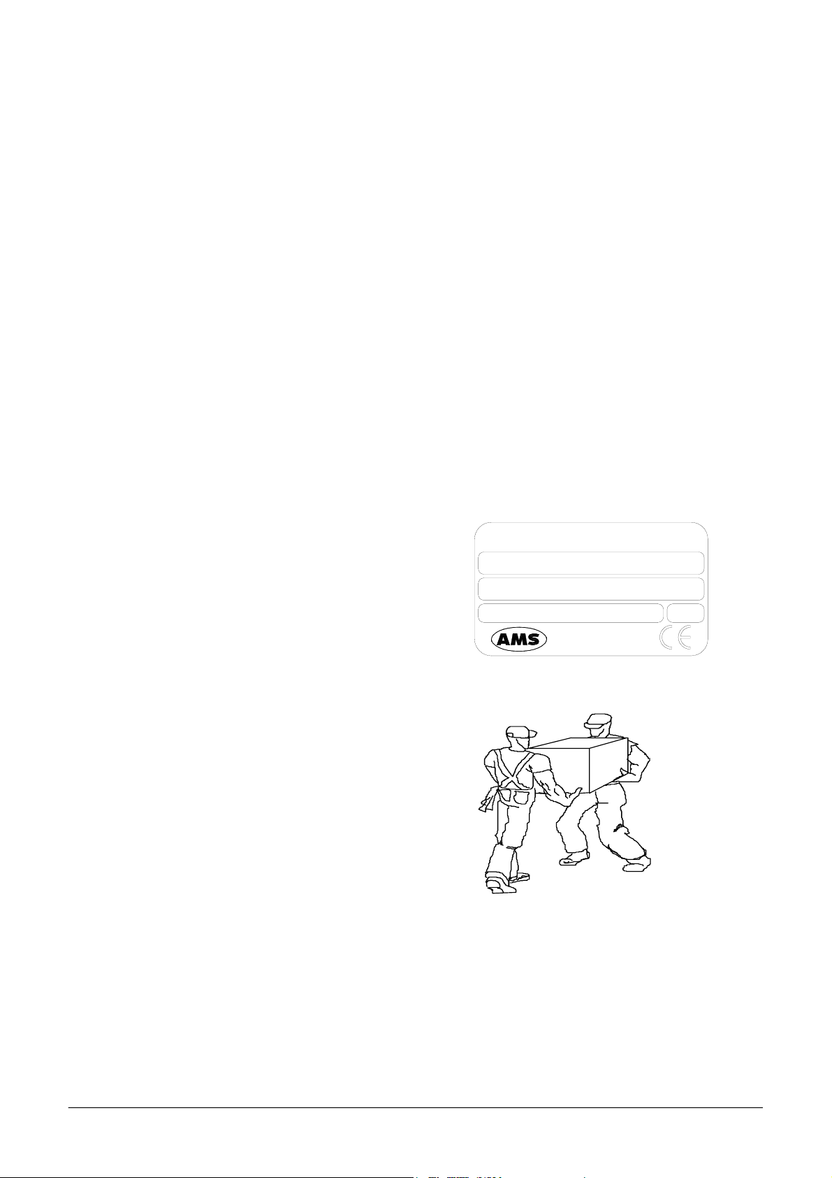
and are undamaged. Make sure the series
number on the delivery note/packing lis
corresponds to that impressed on the plate o
the left side of the instrument.
Open the crate(s)/box from the top and ver
carefully take out:
- the instrument;
- the computer and accessories.
ELLIPSE
S/N
P/N
100 ÷ 230Vac 47 ÷ 63Hz
Analyzer
Medical
System
300W
Rome-Italy
MAKE SURE THAT THE UNPACKING IS CARRIED OUT BY TWO PEOPLE.
Ellipse User Manual Rev.02 19 October 2005 Page 2
Page 6

Chapter 01 - INSTALLATION
Do not discard the delivery crate(s)/box or the packing material until the correct functioning of the
instrument has been ascertained.
Remove all the items from the crate(s)/box very carefully.
Before connecting the "Ellipse", remove the protective packing material placed under the sampling
arm and under the wash station group.
Warning: in the event that it is necessary to repack any or all of the delivered item(s), the following
procedures must be carefully followed:
Reposition the protective packing material under the sampling arm and under the wash station
group.
Tape down (using masking tape if possible) the cover of the samples and reagents housing, the
front panels, and the samples and reagents racks.
Remove the probe from the sampling arm and place it inside a primary tube. Then cap the tube
and tape the cap down.
Be very careful to not bend the wash station cannulas when repositioning the protective packing
material.
Fill the empty spaces around the accessories packed in the crate using “pluriballs” or other
suitable packing material.
Ellipse User Manual Rev.02 19 October 2005 Page 3
Page 7
Chapter 01 - INSTALLATION
1.2 INSTALLATION
The ELLIPSE must only be installed by a qualified technician who has been authorised and trained to
do so. During its installation the system will be checked once again to ensure correct functioning. The
persons who are required to operate the ELLIPSE system must have received the adequate training.
This should also include the "know-how" of the normal maintenance for the instrument. A description
of the maintenance will be found in Chapter 7 of this manual.
ELLIPSE is a complex system, and it is therefore extremely important that it is correctly installed in
order to fully guarantee fine performance. If the installation and use directions, given in this manual,
are not correctly followed and/or safety indications are not respected, AMS cannot guarantee correct
functioning of the instrument. Apart from this, the safety of the operator could be placed at risk.
1.2.1 INSTALLATION SITE SPECIFICATIONS
Ascertain that the ELLIPSE system is not exposed to direct sunlight, draughts, dust or strong magnetic
fields. In addition, please take note of the following conditions required for the location of the
installation:
USE
DEGREE OF POLLUTION
INSULATION CLASS
INSTALLATION CATEGORY
TEMPERATURE
HUMIDITY
ALTITUDE
In covered and dry place
2
I
II
Between 18°- 30°C
20% ÷ 85%
Max 3000 m
Shelf or table with a minimum surface of 75 x 60 cm stable
LOCATION
and free of vibration
Leave a minimum distance of 10 cm around the instrument to
VENTILATION
permit air circulation. Make sure that the front and rear holes
are not blocked by any object
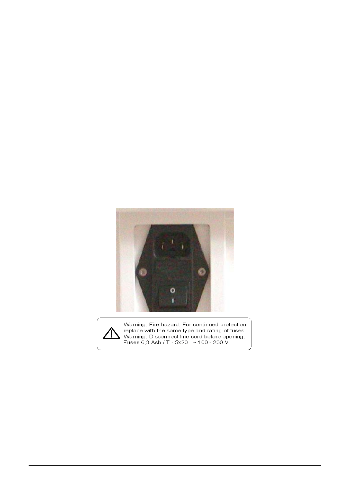
1.2.2 ELECTRIC CURRENT REQUIREMENTS
The power voltages to which the instrument is adapted are indicated on the left-hand side
(see fig. 1). It must be plugged into a plug of the correct voltage.
VOLTAGE
FUSES
100÷ 230 Vac 47/63 Hz ± 10%
6.3 A /T - 5 x 20
Ellipse User Manual Rev.02 19 October 2005 Page 4
Page 8
Chapter 01 - INSTALLATION
NOTE: IT IS ADVISABLE TO MAINTAIN THE MAXIMUM STABILITY OF THE ELECTRICAL CURRENT IN THE
LABORATORY
SUPPLEMENTARY DEVICES IS RECOMMENDED
. WHERE THIS IS NOT POSSIBLE OR ASCERTAINABLE, USE OF THE FOLLOWING
:
ELECTRONIC STABILIZER
Used to stabilise the electric voltage in the laboratory. Any stabiliser with a power potential
greater than 0.5 KW, currently available on the market, can be used.
NO-BREAK MODULE UPS - (Uninterrupted Power Supply)
This module provides two important functions:
- stabilises the main-line power
- supplies current to the instrument in case of a main-line power failure.
1.2.3 CONNECTION OF THE ACCESSORIES
1.2.3.1 POWER SUPPLY
Fig. 1 – Plug (use the feeder cable supplied with the instrument).
The sticker below the plug in indicates the power supply voltage and the values of the fuses.
Ellipse User Manual Rev.02 19 October 2005 Page 5
Page 9
Chapter 01 - INSTALLATION
1.2.3.2 COMPUTER - INSTRUMENT CONNECTION
The instrument and the Personal Computer are connected by one serial RS232 standard cable
(Cod. 9-35-0055-01), which provides the hardware support for the communication.
1.2.3.3 HYDRAULIC CONNECTIONS
The instrument uses Cleaning solution and distilled water for reaction cuvettes cleaning; it uses Rinse
solution for sampling probe cleaning and cuvette blank determination (WBL). A second Rinse
hydraulic line is used for cuvettes quality control checking after washing.
For connecting said solution there are four inlet on the instrument left side identified by roman
numbers as here below specified:
• I Rinse solution (green color)
• II Rinse solution (yellow color)
• III Distilled water (blue color)
• IV Cleaning solution (red color)
The waste hydraulic lines are located on the instrument right side
Further information can be taken on the Hydraulic diagram (SI 16 00571 01 Service manual -chapter
04).
1.2.4 ATTENTION
The following label is found at the rear of the instrument.
CAUTION
TO PREVENT ELECTRIC SHOCK
DO NOT REMOVE BACK PANEL.
NO USER-SERVICEABLE PARTS INSIDE.
REFER SERVING TO QUALIFIED
SERVICE PERSONNEL
NOTE: THE REAR PANELS OF THE INSTRUMENT MUST NEVER BE OPENED WITHOUT HAVING FIRST
SWITCHED THE INSTRUMENT OFF AND DISCONNECTED THE ELECTRICITY CABLE
Ellipse User Manual Rev.02 19 October 2005 Page 6
.
Page 10
Chapter 01 - INSTALLATION
THE MAINTENANCE AND CLEANING PROCEDURES FOUND IN CHAPTER 07 OF THIS MANUAL MUST BE
RESPECTED AT ALL TIMES
BEFORE INSTRUMENT MAINTENANCE OPERATION
. REMEMBER TO FOLLOW THE DECONTAMINATION PROCEDURE WHEN REQUIRED
(SEE CHAPTER 07).
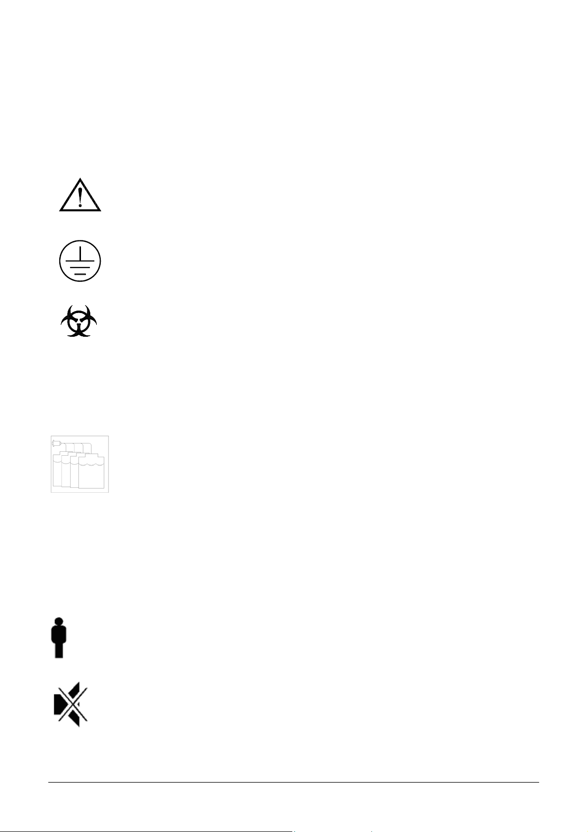
1.2.5 SYMBOLS
ATTENTION: READ THE INSTRUCTIONS IN THE USER MANUAL
TERMINAL OF TOTAL MASS PROTECTION (CONDUCTOR)
BIOLOGICAL HAZARD
(LOCATED NEAR THE REACTION PLATE AREA)
Carefully manipulate all the consumables and the wastes produced during the
analysis routines. Use appropriate protective garment. Disposal of wastes must
be done in compliance with applicable regulation. It is recommended to
periodically check the level in the waste container, in order to avoid overflow.
INDICATES THE BOTTLES CONNECTION
I RINSE SOLUTION
II
III
IV
STAND-BY BUTTON
RINSE SOLUTION
DISTILLED WATER
CLEANING SOLUTION
BUZZER FORCE OFF BUTTON
Ellipse User Manual Rev.02 19 October 2005 Page 7
Page 11

Chapter 01 - INSTALLATION
BARCODE READER BUTTON
1.2.6 REGULATORY COMPLIANCE
The ELLIPSE instrument complies with:
• European Directive 98/79/CE for In Vitro Diagnostic Devices
1.2.7 LIMITATION OF USE
The ELLIPSE can not be used by blind operators because the user interface with the system requires a
monitor.
Furthermore the ELLIPSE must be used with particular caution by color blind operators because the
graphic interface displays different colors with different meaning.
1.2.8 BARCODE READER
A bar code reader can be optionally installed on the ELLIPSE. The barcode reader has a laser micro-
scanner classified as Class II laser device. It is compliant with applicable safety regulations.
WARNING TURN OFF ALWAYS THE INSTRUMENT before removal of those panels and
covers that protect from any interference and/or exposure to the laser beam active during sample
identification.
1.2.9 WARRANTY
AMS guarantees the substitution of all defective components and/or materials for a period of time not
above of fourteen months starting from the date of invoicing. Saying warranty, as well as Technical
Assistance, generally is intended furnished as net ex factory Rome.
This warranty does not include consumable and instrument parts in contact with liquids. All
components not covered by the warranty are reported in the table on the next page.
Besides warranty does not cover damage caused by:
- improper use of the ELLIPSE instrument (or however not according to the Producer or Seller
instructions)
- bad transport
- insufficient (or missing) preventive maintenance by the User
In particular any damages due to the transport must be immediately reported to the carrier when he
delivers.
Ellipse User Manual Rev.02 19 October 2005 Page 8
Page 12

Chapter 01 - INSTALLATION
1.2.10 CONSUMABLES AND ACCESSORIES PARTS LIST OUT OF WARRANTY
Description Type
Quantity
(Pieces)
Code
Reagents containers 35 ml 12 C101-00190-00
Reagents containers 6 ml 12 C101-00191-00
Samples cups 0.8 ml 1000 AS650002
Short samples cups 1 ml 1000 AS650100
Adapter for short samples cups 1 9-01-0609-00
Reaction sectors 6 C101-00217-00
Washing solution bottle 2 lt 1 9-35-0041-00
Bottle level sensor 1 9-05-0078-00
Tubing Kit for peristaltic pump 2 65-01835-00
Tubing Kit – complete 1 65-01836-00
Cleaning solution 250 ml 2 ASRN0020
Rinse solution 50 ml 1 ASRN0021
Sampling probe (internal needle) 1 05-00707-00
Complete Sampling probe 1 10-00703-00
Drying Pad 1 01-01920-00
Halogen Lamp (6 V - 10 W) 1 9-35-0016-00
Interferential filters Kit (Stablife) 1 65-02017-00
Fuse 6,3 A-T 5x20 10 C132-01238-08
Inlet/outlet fitting for Rinse & Clean conts 1 01-01224-00
Cuvettes protection cover 1 05-01249-00
Reagent protection cover 1 10-00584-00
Reagent plate 1 10-00585-00
Samples rack 1 05-01829-00
Washing station, first or second cannulas (A) 1 05-01633-00
Washing station, third cannula (B) 1 05-01633-01
Washing station, fourth cannula (C) 1 05-01638-00
Washing station, fifth cannula without pad (D) 1 05-01919-00
Diluter Micro-Pump 1 05-01710-40
Air Micro-Pump (µP 6) 1 05-01711-20
Micro-Pump (µP 2 ÷5) 1 05-01826-16
Predilution rack 1 05-01735-00
Solenoid Valve –2 way 1 9-35-0035-00
Solenoid Valve –3 way 1 9-35-0036-00
Ellipse User Manual Rev.02 19 October 2005 Page 9
Page 13

Chapter 02 - GENERAL DESCRIPTION
CHAPTER 02 – GENERAL DESCRIPTION
INDEX
2.1 INTENDED USE AND SYSTEM DESCRIPTION........................................................... 2
2.2 ANALYSES CYCLE .......................................................................................................... 3
2.2.1 REACTION PLATE ........................................................................................................... 3
2.2.2 REACTION PLATE CYCLE ............................................................................................. 3
2.2.3 SAMPLING ARM - OPERATIONAL SEQUENCE ......................................................... 4
2.2.4 SAMPLING SYSTEM........................................................................................................ 5
2.2.5 WASH STATION ............................................................................................................... 6
2.2.6 WASH STATION CYCLE ................................................................................................. 6
2.3 TECHNICAL-OPERATIVE SPECIFICATIONS............................................................... 7
2.3.1 SOFTWARE AND COMPUTER SPECIFICATIONS....................................................... 8
2.3.2 OPTIONAL MODULES .....................................................................................................9
2.3.3 DIMENSIONS, WEIGHT AND OPERATING ENVIRONMENT.................................... 9
2.3.4 INSTALLATION SPECIFICATIONS................................................................................9
Ellipse User Manual Rev.02 19 October 2005 Page 1
Page 14

Chapter 02 - GENERAL DESCRIPTION
2.1 INTENDED USE AND SYSTEM DESCRIPTION
The “Ellipse” is a random access, computer controlled, counter-top, clinical analysis instrument.
The system can perform 138 tests per hour and has a machine cycle of 26 seconds. Its execution
time ranges from a minimum of 18 seconds to a maximum of 1040, depending on the analysis
method chosen.
The first time the system is used for laboratory analyses, the operator must configure the system
based on the specific needs of that laboratory; i.e.: the chemistry parameters and the reagents racks,
along with the normal, calibrated and control values, must all be defined.
The “Ellipse” is an “OPEN” system that allows configuration with different reagents selected by
the customer in order to fit his needs.
NOTE:
In order to assure the analytical performances of the system “instrument + reagents”, it is
responsibility of the laboratory staff to use reagents, controls and calibrators validated on the
“Ellipse”, or in alternative, to qualify other reagents, controls and calibrators in compliance with
the applicable regulations.
The daily routine analyses will be carried out according to patient sample arrival in a sequential and
continuous, non-stop manner.
The work list is organized using a loading rack holding up to 8 patient samples. Rack loading is
non-stop.
The racks can accommodate test tubes or micro caps. The bar code for primary tubes and reagent
containers is an optional feature.
When the system, the analytical unit and the computer, is turned on the color-meter lamp is supplied
with low voltage power (1.2 volts), the sampling arm pre-heater remains turned off, while instead
the reaction plate heater, the reagents refrigerating unit (optional module) and the electronic
components are turned on.
In this phase, the "Stand-by" light, placed on the front panel, will flash until the reaction plate
reaches a temperature of 36° C. When this temperature is reached, the "Stand-by" light will stop
flashing and will remain constantly lit.
In the case of system failure or malfunction, the "Ready" light, situated on the front panel of the
instrument, will light up red.
In order to access the main program, double click on the "Analyzer" icon on the computer desktop.
Ellipse User Manual Rev.02 19 October 2005 Page 2
Page 15

Chapter 02 - GENERAL DESCRIPTION
The main menu - "System Monitor" - will appear.
Whenever any system function is launched, the color-meter lamp and the sampling arm pre-heater
will receive regular power.
2.2 ANALYSES CYCLE
2.2.1 REACTION PLATE
The reaction plate of the "Ellipse" system contains 6 disposable racks with 20 reaction cuvettes
each.
The racks can be removed individually.
The basic operating cycle of the reaction plate takes 26 seconds. This cycle includes: optic reading
of the cuvettes in incubation, aspiration and dispensing of the reagents and the samples by the arm,
along with the relative positioning of the plate.
The reactions take place at 37° C. This temperature is maintained constant by a controlled heating
unit placed under the reaction plate.
2.2.2 REACTION PLATE CYCLE
After reagents and samples have been placed in cuvette #1, the reaction plate will rotate 40
positions counter-clockwise, so as to bring the first cuvette to be analyzed in front of the color-
meter for reading with either one or two wavelengths, if required.
The plate will then, moving clockwise, carry out all the readings of any other prepared cuvettes.
After having effectuated all the readings, the plate will move counter-clockwise to its initial
position minus one cuvette, ready for a new dispensing.
In this manner, the reaction cuvettes move clockwise 1 - 2 - 3 - 4 for dispensing, washing and the
relative readings.
Ellipse User Manual Rev.02 19 October 2005 Page 3
Page 16

Chapter 02 - GENERAL DESCRIPTION
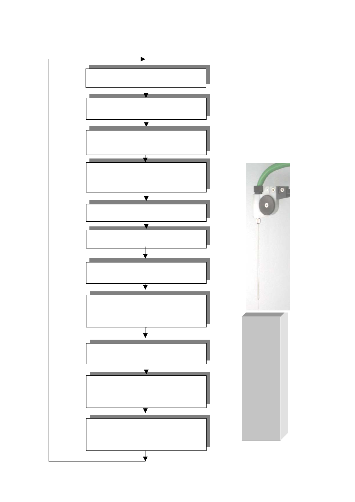
2.2.3 SAMPLING ARM - OPERATIONAL SEQUENCE
1. The sampling arm lifts up from the wash well and carries out a wash cycle;
2. The arm moves toward the specific reagent container, while the diluter aspirates an air bubble
to separate the rinse column from the reagent;
3. The arm lowers itself into the reagent, below the level indicated by the sensor, and aspirates the
required quantity of reagent. If the method requires a Rinse (used in order to reduce the
possibility of negative contamination between the water column and the reagent) an extra
amount of reagent (not used in the analysis) will be aspirated before the quantity of reagent
necessary for the analysis, along with another air bubble for their separation;
4. While the diluter aspirates a second air bubble, the arm rises and then lowers into the wash well
so that it can be washed externally, to minimize cross contamination;
5. The arm moves to the specified sample and aspirates a third air bubble;
6. Once the level sensor has indicated the presence of the liquid, the arm stops and aspirates the
sample;
7. The arm once again is raised, while the diluter aspirates a fourth air bubble to prevent sample
loss;
8. At this point, the arm returns to the wash well in order to clean the outside of the probe and
aspirates a fifth air bubble;
9. The arm moves to the reaction plate, dispenses, and mixes the reagent and sample in the
reaction cuvette for incubation and reading;
10. The arm returns to the wash well and carries out a probe wash cycle.
Ellipse User Manual Rev.02 19 October 2005 Page 4
Page 17
Chapter 02 - GENERAL DESCRIPTION
(
)
2.2.4 SAMPLING SYSTEM
Aspiration of Air
Aspiration of Reagent
Aspiration of Air
To separate reagent from serum
To wash well to clean the
probe
Aspiration of air
Aspiration of serum
Aspiration of air
To wash well to clean the
probe
Aspiration of air
Dispensing and mixing in
cuvette
To wash well for final
wash
H2O
AIR
RGT
AIR
AIR
SERUM
AIR
Ellipse User Manual Rev.02 19 October 2005 Page 5
Page 18

Chapter 02 - GENERAL DESCRIPTION
2.2.5 WASH STATION
The reaction plate wash station is made up of a series of five small needles situated on one side of
the reaction plate. Said needles are opportunely connected to the valve and pump system for
emptying, washing and drying operations (please see the hydraulic diagram).
2.2.6 WASH STATION CYCLE
The wash station carries out its operations alternating upward and downward movement. In its
downward movement phase the needles are guided in such a manner as to carry out the following
operations:
• The first needle, using the central cannula, removes the reaction mix while the external cannula
dispenses, shower-like fashion, the wash solution; after that the external cannula dispenses
wash solution and then the liquid is aspirated from the central cannula;
• The second needle operates exactly like the first but uses distilled water instead;
• The third needle operates exactly like the first but dispenses rinse solution into the cuvette so
that an optics check can be performed (if the results are negative, the cuvette is discarded);
• The fourth needle aspirates the Rinse solution used for the optic check.
• The fifth needles dries the sides.
All these operations are part of the routine operation of the instrument. Every reaction cuvette is
washed at the end of each round of analysis.
The reusability (optical integrity) of each reaction cuvette is always tested before the next round of
analysis.
Ellipse User Manual Rev.02 19 October 2005 Page 6
Page 19

Chapter 02 - GENERAL DESCRIPTION
2.3 TECHNICAL-OPERATIVE SPECIFICATIONS
♦ Completely automatic, random access, computer
DESCRIPTION
REACTION TYPES
TEST SELECTION MODES
PRODUCTIVITY
OPERATING TEMPERATURE
IN LINE REAGENTS
SAMPLE CONTAINERS
controlled, counter-top, non-stop loading clinical
chemistry and immunoturbidimetric analysis
instrument
♦ End Point, Fixed Time, Kinetic, Bichromatic,
Differential
♦ Selective, Batch, Profile, STAT
♦ 138 tests per hour
♦ 37° C
♦ 24 removable containers (capacity 35 and 6 ml)
♦ Reagent plate cooling unit (Optional)
♦ 12 positions for Controls and Standards
♦ Positive Bar Code Reader (Optional)
♦ Primary tubes (diameter from 8 to 16 mm; height
up to 100 mm) cups from 1 to 4 ml
SAMPLE LOADING
MINIMUM REACTION
VOLUME
MAXIMUM REACTION
VOLUME
SAMPLING ARM
DILUTER
♦ 4 racks, each having 8 positions for non-stop
sample loading
♦ Positive Bar Code Reader (Optional)
♦ 220 µl
♦ 550 µl
♦ A single mechanical arm performs all the sampling
operations and is equipped with:
• A volume level sensor
• Pre-heating of the reagent(s) to 37 °C
• Automatic probe washing
♦ Integrated syringe-free module having the
following specifications:
• Sample volume: 2 µl ÷ 99 µl (1 µl incr.)
• Reagent 1 volume: 3 µl ÷ 500 µl (1 µl incr.)
• Reagent 2 volume: 3 µl ÷ 330 µl (1 µl incr.)
• Reagent 3 volume: 3 µl ÷ 330 µl (1 µl incr.)
Ellipse User Manual Rev.02 19 October 2005 Page 7
Page 20

Chapter 02 - GENERAL DESCRIPTION
PRECISION
READING SYSTEM
OPTIC SYSTEM
CUVETTE OPTIC LENGTH
WASHING STATION
REACTION PLATE
♦ CV < 1 % at 2 µl
♦ Direct reading
♦ Photometer: double ray, interferential filters
♦ Wavelength: 8 narrow band – from 340 nm to 620
nm – interferential filters plus one available
optional filter position
♦ Light source: 6V/10W halogen bulb
♦ Linearity range: up to 3,500 Abs
♦ Resolution: 0.0005 Abs
♦ 6 mm
♦ Composed of five probes that empty, wash and dry
the reaction cuvettes.
♦6 individually replaceable racks with 20 cuvettes
each
♦Incubation temperature: 37°C
2.3.1 SOFTWARE AND COMPUTER SPECIFICATIONS
TYPE
CPU
♦ IBM Compatible
♦ Pentium IV 500 MHz, 512 Kb Cache or plus
♦ RAM 256 Mb or plus
MEMORY
♦ Hard Disk 20 Gb or plus
♦ Floppy Disk 3 1/2” 1.44 Mb
Colour SVGA 15’’ low radiation
MONITOR
Resolution 800 x 600 pixels;
max number of colors 65536 (16 bit)
PRINTER
♦ 80 Columns impact graphic (EPSON LX 300)
KEYBOARD AND MOUSE
INTERFACE
♦ PS2
♦ One Bi-directional RS 232C serial ports and one
parallel (one second serial port for the Host link)
♦ Multitasking WINDOWS XP Home edition
SOFTWARE
AVAILABLE LANGUAGES
Ellipse User Manual Rev.02 19 October 2005 Page 8
♦ Italian, English, Chinese, Czech. Software to be released
soon in these languages: Russian, Portuguese, French,
Polish. Upon request it is possible to release the software
in other languages.
Page 21

Chapter 02 - GENERAL DESCRIPTION
♦ Disable all the energy saving options
SETTINGS
♦ Disable the screen saver
♦ Select English “USA” as language, dot as decimal
symbol and date and time in Regional setting
NOTE: Even though the computers demonstrate the same technical and operative characteristics,
some of these could have different hardware installed.
This could cause problems for the Ellipse software when running tests (A message appears
indicating “Random” error or blocks the program).
Therefore, if the PC is bought separately/locally, it is highly recommended to test the system before
proceeding with the installation at customer laboratories.
Consequently, AMS denies any responsibility for software problems that are due to buying the
computer separately from the instrument.
2.3.2 OPTIONAL MODULES
♦ POSITIVE BAR CODE READER
2.3.3 DIMENSIONS, WEIGHT AND OPERATING ENVIRONMENT
♦Height: 53 cm
DIMENSIONS
♦Width: 57 cm
♦Length: 75 cm
WEIGHT
OPERATING
ENVIRONMENT
♦35 kilos
♦Temperature: 18 °C ÷ 30 °C
♦ Relative Humidity: 20% ÷ 85%
2.3.4 INSTALLATION SPECIFICATIONS
♦Input voltage: 100 ÷ 230 Vac
♦Input frequency: 47 ÷ 63 Hz
POWER SUPPLY
♦Power consumption:
♦300 W for the analysis unit
♦400 W for the work station
Ellipse User Manual Rev.02 19 October 2005 Page 9
Page 22

Chapter 02 - GENERAL DESCRIPTION
Warning: in order to assure proper instrument functioning, the manufacturer strongly advises the
use of a stable tension supply outlet (+/-10%). If it is not possible to guarantee said stability, the
manufacturer suggests the use of:
♦ UPS (Uninterrupted Power Supply)
♦ ELECTRONIC STABILIZER
Ellipse User Manual Rev.02 19 October 2005 Page 10
Page 23

Chapter 03 - DESCRIPTION OF INSTRUMENT SOFTWARE
CHAPTER 03 - DESCRIPTION OF INSTRUMENT
SOFTWARE
INDEX
3.1 SYSTEM MONITOR………………………………...……………..…………………….………..3
Warning Lights.................................................................................................................................... …….5
Legends ........................................................................................................................................................ 7
Status Line.................................................................................................................................................... 8
Menus available under System Monitor: ..................................................................................................... 9
Command Buttons………………………………………………………………………..……………....10
Check button ..............................................................................................................................................11
Order button ............................................................................................................................................... 11
Print button................................................................................................................................................. 13
Graph button............................................................................................................................................... 13
Rerun button............................................................................................................................................... 14
Edit Results button ..................................................................................................................................... 15
Move to Archive button ............................................................................................................................. 16
Unload button............................................................................................................................................. 16
3.1.1 START WORK................................................................................................................................ 17
Wash all cuvettes........................................................................................................................................ 17
Water Blank Level ..................................................................................................................................... 18
Calibration & Quality Control.................................................................................................................... 18
Work List ................................................................................................................................................... 19
Start Running ............................................................................................................................................. 19
3.2 CHECKS ........................................................................................................................................... 20
WBL........................................................................................................................................................... 21
Main Area.............................................................................................................................................. ….21
Reagent Volume......................................................................................................................................... 23
Main Area................................................................................................................................................... 23
Details Area……………………………………………………….……………………………………...24
Reagent Configuration ............................................................................................................................... 25
Predilution Rack......................................................................................................................................... 27
3.3 ROUTINE ......................................................................................................................................... 31
Work List Setup .........................................................................................................................................32
Unassigned Sample .................................................................................................................................... 33
Saving data for more than one patient........................................................................................................ 37
Deleting a Patient………………………………………………………………………………….……...37
Ellipse User Manual Rev.02 19 October 2005 Page 1
Page 24

Chapter 03 - DESCRIPTION OF INSTRUMENT SOFTWARE
Deleting a rack…………………………………………………………………….……………………...38
Result by Patient ........................................................................................................................................ 40
Printing Data ..............................................................................................................................................43
Main Area................................................................................................................................................... 44
Precision check........................................................................................................................................... 46
Calibration & Quality Control Setup ......................................................................................................... 47
Calibration Programming........................................................................................................................... 49
Editing Calibration ..................................................................................................................................... 50
Calibration Results ..................................................................................................................................... 51
Quality Control Results.............................................................................................................................. 58
Quality Control Graphs .............................................................................................................................. 60
Receive from Host...................................................................................................................................... 61
3.4 ARCHIVE ......................................................................................................................................... 62
Patients ....................................................................................................................................................... 63
Main Area................................................................................................................................................... 63
Details Area................................................................................................................................................ 64
Calibration.................................................................................................................................................. 65
Main Area................................................................................................................................................... 66
Details Area................................................................................................................................................ 68
Backup........................................................................................................................................................ 69
Restore........................................................................................................................................................ 70
Tests Counter ............................................................................................................................................. 71
Event Log................................................................................................................................................... 72
3.5 PARAMETERS ................................................................................................................................ 73
Inserting the Password ............................................................................................................................... 74
Profiles ....................................................................................................................................................... 75
Ratio ........................................................................................................................................................... 77
Standards.................................................................................................................................................... 82
Controls...................................................................................................................................................... 87
Options ....................................................................................................................................................... 91
Print Order.................................................................................................................................................. 92
Report Options ........................................................................................................................................... 93
Password Setting ........................................................................................................................................ 94
3.6 HELP................................................................................................................................................. 96
Guide F1.................................................................................................................................................... 97
Software versions ....................................................................................................................................... 98
3.7 SHUT DOWN................................................................................................................................... 99
Ellipse User Manual Rev.02 19 October 2005 Page 2
Page 25
y
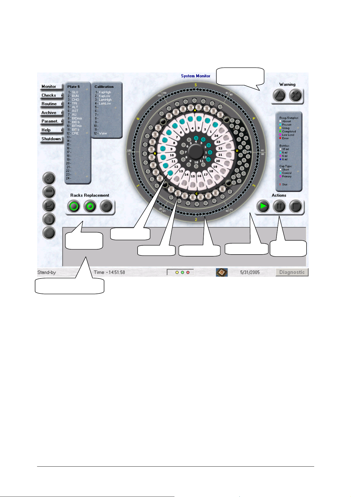
3.1 SYSTEM MONITOR
Chapter 03 - DESCRIPTION OF INSTRUMENT SOFTWARE
Warning Lights
Operative
Buttons
Reagent tray
Sample tra
Reaction tray
Desk Top area
Operative
View Data/Details Area
The system’s management software is extremely user-friendly and, moreover, allows maximum
flexibility in its use.
The operator can access the management software by simply turning on the instrument. If the last
instrument Shut Down was due to a Fatal Error or if the Analyzer is at the time turned off, the user
must double click on the Analyzer icon located on the computer Desk Top.
The user interface screen is subdivided into two main areas:
the Desk Top area
the View Data/Details Area
The Desk Top area is a graphic illustration of the instrument that allows the operator to easily
identify each
single item and its status. It includes:
√ A reagent tray with twenty-four reagents and twelve Standards and Controls positions;
√ A Samples tray composed by four racks with eight positions each.
Ellipse User Manual Rev.02 19 October 2005 Page 3
Page 26
Chapter 03 - DESCRIPTION OF INSTRUMENT SOFTWARE
√ A reaction tray composed by six racks with twenty cuvettes each.
View Data/Details Area
Located in the lower section of the System Monitor mask, the View Data/Details Area contains
precise, detailed information concerning the item selected (Cuvette, Samples, Reagents, Standards
and Controls).
It is possible to view data details regarding single items by clicking on them whenever the mouse
pointer turns into a question mark as it passes over that particular element.
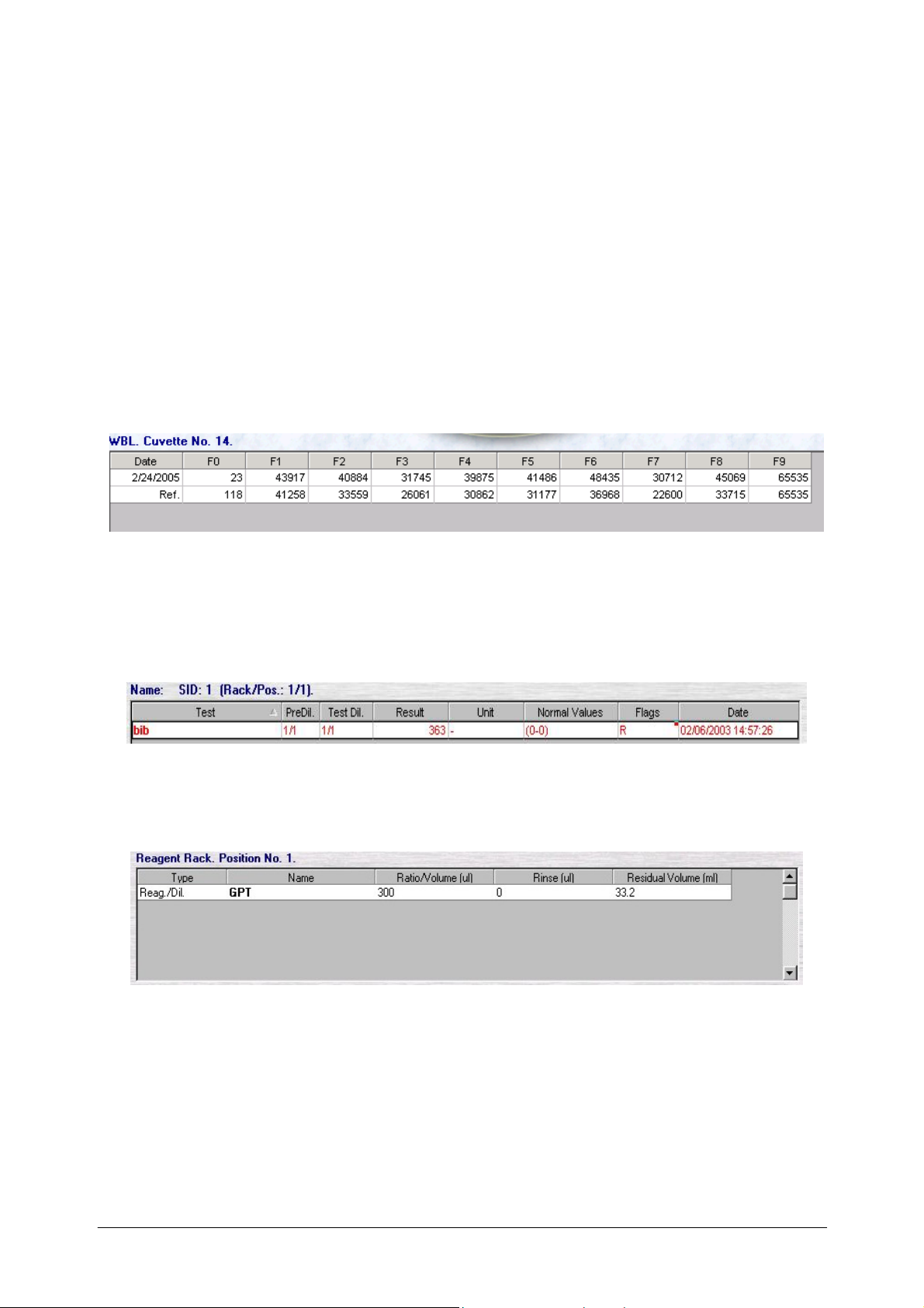
• If the operator selects a given position on the Reaction Plate, by placing the mouse pointer
over the required item:
a table containing the WBL values of the cuvette selected (both the main channel and the
reference channel values) will be viewed. The Print button will also be activated.
• If the operator selects a given position on the Samples Rack, by placing the mouse pointer
over the required item:
a table listing the tests programmed to be run on that sample will appear in the lower
portion of the window and information regarding the sample itself (patient name, sample
ID, rack and position) will appear in the upper portion of the window.
• If the operator selects a given position on the Reagents Rack, by placing the mouse pointer
over the required item, the below-illustrated table will appear allowing the user to view
information regarding the selected Reagent.
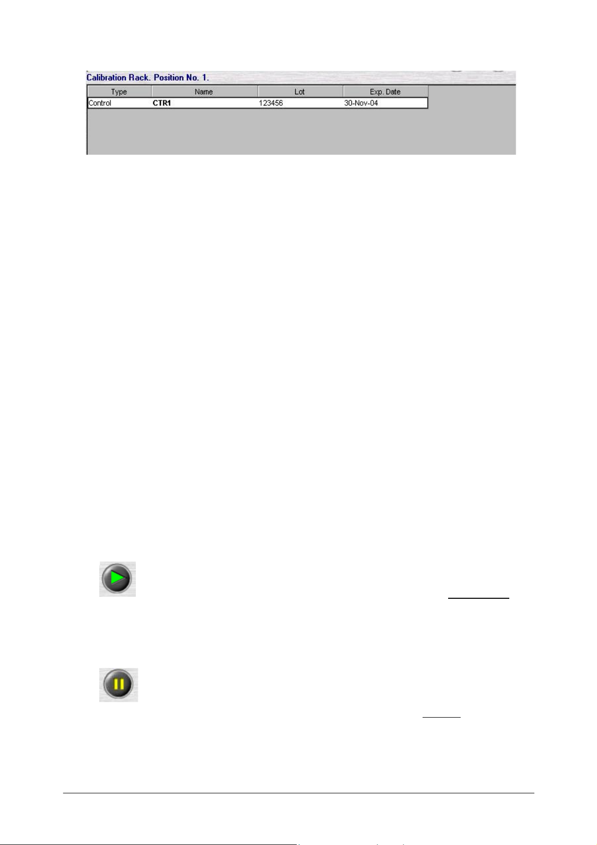
• If the operator selects a given position on the Controls or Standards, by placing the mouse
pointer over the required item, the below-illustrated table will appear allowing the user to
view information regarding the selected Control or Standard.
Ellipse User Manual Rev.02 19 October 2005 Page 4
Page 27
Chapter 03 - DESCRIPTION OF INSTRUMENT SOFTWARE
WARNING LIGHTS
There are two types of alarms:
• The first type is a brief visual text message, which appears in the lower, left-hand portion
of the screen, up to the operative buttons. It can inform the operator that either there is “no
instrument connection”, or the “cover is open”, or that a “remote link” is in operation.
• The second are Warning Buttons (located in the upper, right portion of the mask) and they
can be:
- either a “Warning” represented by a triangle that lights up yellow. If the operator clicks
on this button, it is possible to view in the Details Area those events which caused the
warning (e.g.: liquid(s) finished).
- or a “Fatal Error” represented by an X that lights up red. Whenever a fatal error is
signalled, only those readings that have already been carried out will be saved; those
operations being carried out at the time are interrupted (e.g.: incubation). After every
“Fatal Error”, the user must have the instrument carry out a Wash cuvette cycle. If the
operator clicks on this button, it is possible to view in the Details Area those events that
caused the warning (e.g.: temperature error).
At this point, it can be useful for the operator to consult Event Log, listed under the
Archive menu, where all instrument status information is memorized, in order to have
more information regarding the occurrence.
Operative Buttons “Actions”:
START (green triangle): allows the operator to access the Start Work mask
where it is possible to start the running of the various tests and of any other operation regarding
the instrument.
PAUSE: temporarily interrupts only the sampling process. It does not interrupt
incubation, nor the reading of already dispensed samples. To restart, press START
.
Ellipse User Manual Rev.02 19 October 2005 Page 5
Page 28
Chapter 03 - DESCRIPTION OF INSTRUMENT SOFTWARE
STOP: halts instrument functioning - the sampled tests are lost.
Operative Buttons “Racks Replacement”:
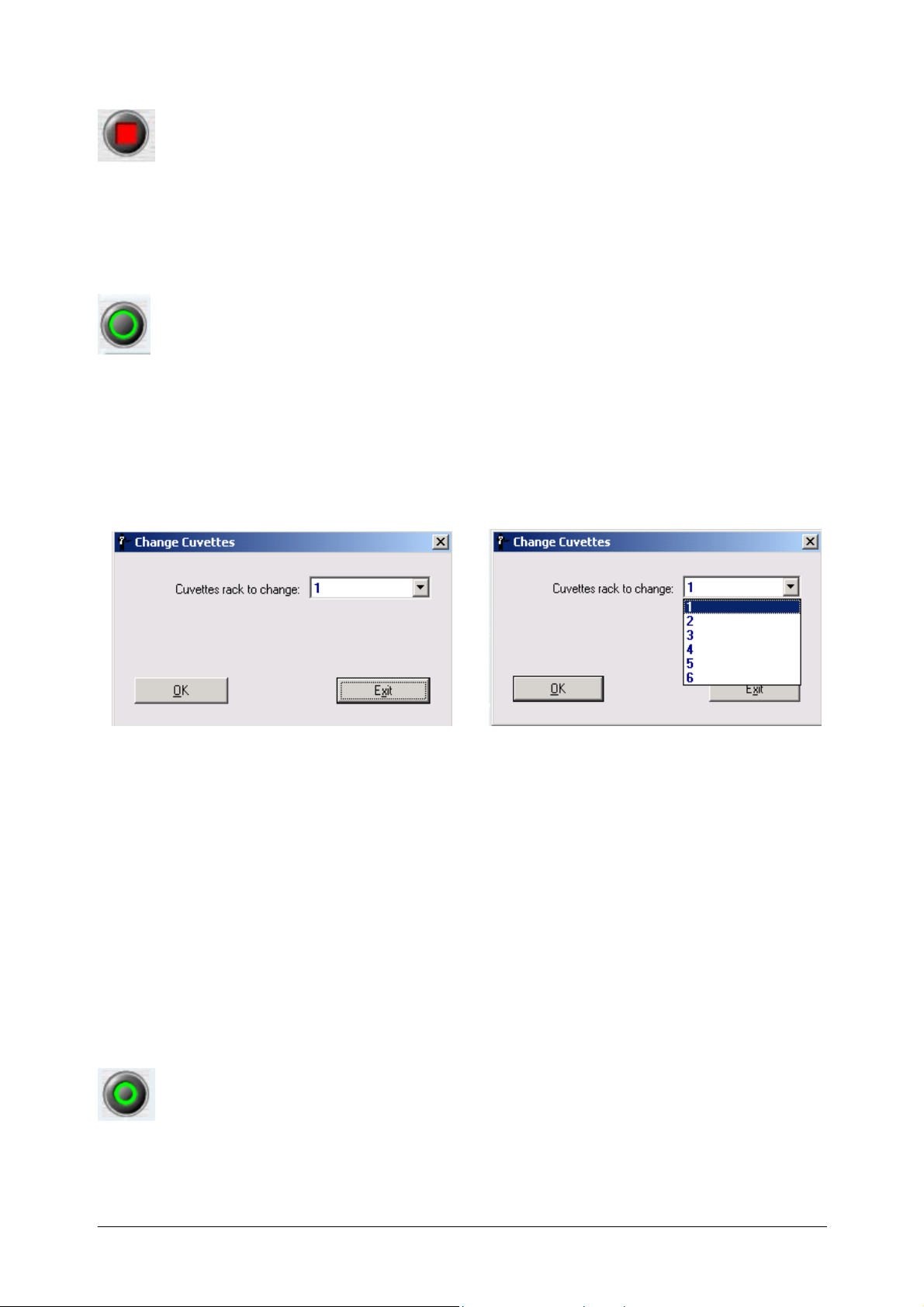
Change cuvettes: allows the operator to change cuvettes rack. Clicking on it, the
following dialog box will automatically open and rack selection to be replaced can be done
clicking on the pull-down menu from 1 to 6.
Clicking on “OK” the instrument pass to the Priming and then in Stand-By condition while the
reaction plate turns up to bring the selected position in front of the operator to allow the cuvette
rack replacement.
Click on “OK” into the message that appears after reaction plate positioning to confirm the
happened replacement.
Cuvettes rack can be changed only when the instrument is not performing any operation or
procedure. In such condition, the button is made disable.
Whenever one or more cuvettes illustrated in the Reaction Plate are coloured Red, it is because the
instrument cannot perform the required readings on them due to the fact that they are not perfectly
transparent, or rather; their transparency is below the minimum or above the maximum limit
acceptable to the instrument program. If the operator wishes to view the filter readings, he/she can
do so from within the Details Area.
Whenever a cuvettes rack is inserted for the first time in the Reaction Plate, it is indicated in red
under System Monitor because the instrument does not have that data necessary for the
mathematical equations needed to calculate test results. Therefore, it is necessary to carry out a
WBL for that cuvettes rack (auto-zeroing) in order to be able to use it.
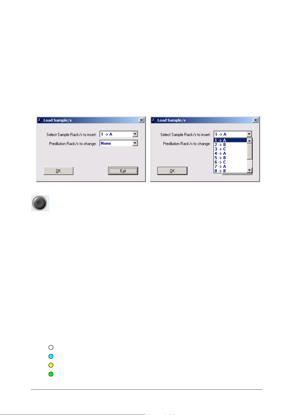
Load Sample/s: allows the operator to load samples rack. Clicking on it, the following
dialog box will automatically open and rack selection to be replaced can be done on the pull-down
menu, among those programmed, in the reported position A, or B, or C or D, defined by the
instrument.
Ellipse User Manual Rev.02 19 October 2005 Page 6
Page 29
Chapter 03 - DESCRIPTION OF INSTRUMENT SOFTWARE
Clicking on “OK”, the sample plate turns up to bring the selected position in front of the operator,
to allow the sample rack loading.
Click on “OK” into the message that appears after sample plate positioning to confirm the
happened loading.
Samples rack can be loaded at any time, even if the instrument is in running condition.
In this case, pushing the loading operative button, the instrument pass from the Running to the
Pausing and then to the Pause condition, to allow the selected rack loading.
Click on “OK” into the message that appears after sample plate positioning to confirm the
happened loading; click on the START button and confirm pushing OK in order to restart the
running.
Load Reagents: allows the operator to load reagents. The button is able in Running
condition only. Clicking on it, the following dialog box will automatically open and ALL
selection to load reagents can be done on the pull-down menu.
Clicking on “OK” the instrument pass from the Running to the Pausing and then to the Pause
condition the allow the refill of one or more then one used reagents, or one new reagent
configuration loading.
Click on “OK” into the message that appears after reagent plate positioning to confirm the
happened loading; click on the START button and confirm pushing OK in order to restart the
running.
LEGENDS
There are three legends and one symbol to be found under System Monitor and they are the
following:
• A Legend regarding the colours associated with certain visual text messages
concerning reagent and sample status: (upper right)
Reag./Samples:
White (absent)
Sky blue (present)
Yellow (in use)
Green (completed)
Ellipse User Manual Rev.02 19 October 2005 Page 7
Page 30
Chapter 03 - DESCRIPTION OF INSTRUMENT SOFTWARE
Magenta (low level)
Red (error - no sample or reagent)
• A legend regarding the various types of reagent bottles having different volume
capacities, that can be selected for use by the operator (medium right)
white 35 ml
sky blue 6 ml
magenta 6 ml
blu 6 ml
• A legend regarding the various types of test-tubes having different volume capacities,
that can be selected for use by the operator (lower right)
white (short – approximately 1 ml)
sky blue (conic– approximately 2 ml)
magenta (primary tube)
By clicking on “Options” under the “Parameters” menu, the operator can select the reagent
bottle to be used by default. The reagent code will be written in the colour of the bottle that
contains that reagent.
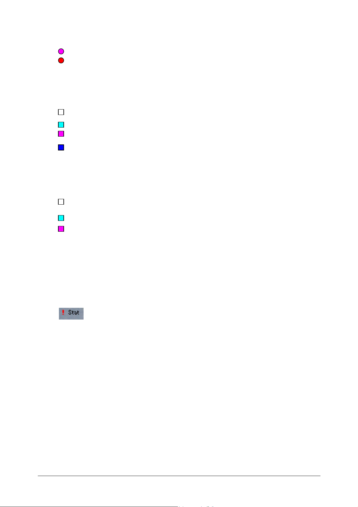
• A symbol regarding STAT
Samples having this symbol will be processed first of all the other programmed
and loaded samples.
STATUS LINE
The Status Line, lower left, contains information regarding the functioning condition of the
instrument. Said information allows the operator to follow and check the status of instrument
operation.
Stand By
Stop
Washing
Running WBL
Ellipse User Manual Rev.02 19 October 2005 Page 8
Page 31

Chapter 03 - DESCRIPTION OF INSTRUMENT SOFTWARE
Running
Pause
Pausing
Safe
Priming
Moreover, in the Status Line, are reported the following information:
Icon indicating a fault sample reading executed by the Bar Code reader.
If the operator places the mouse pointer on this icon, it is possible to view the Firmware
version.
MENUS AVAILABLE UNDER SYSTEM MONITOR:
⇒ Monitor
⇒ Checks
⇒ Routine
⇒ Archive
⇒ Parameters
⇒ Help
⇒ Shut Down
Ellipse User Manual Rev.02 19 October 2005 Page 9
Page 32

Chapter 03 - DESCRIPTION OF INSTRUMENT SOFTWARE
COMMAND BUTTONS
The Command Buttons are automatically activated as needed and have the following functions:
Make validated the results of a given Test (Check button);
Reorder the viewed data (Order button);
Print the viewed data (Print button);
View an absorbance graph (Graph button);
Repeat an already run test (Rerun button);
Modify the results of a test (Edit button)
Save and File results in the Archive (Move to Database button);
Send the data to the remote computer (Unload button)
The various icons are activated in accordance with the mask being used. It is possible to recognize
an inactive button by its opaque colouring or by the fact that it cannot be viewed. If the user places
the mouse pointer over an icon, a visual text message will appear describing the corresponding
function.
Ellipse User Manual Rev.02 19 October 2005 Page 10
Page 33

Chapter 03 - DESCRIPTION OF INSTRUMENT SOFTWARE
CHECK BUTTON
Working within the Patient Results window and within the Test Results window (even under
System Monitor), the operator has the possibility to verify, select and confirm the results of the
tests by using the Check button located on the Desk Top. By selecting, from the offered list, a row
containing a result deemed correct (e.g.: the same test repeated for the same patient), the operator
can, by clicking on this command, make the selected test “valid”. The system will automatically
show the examined data in bold print, in order to make it more readily visible to the user.
ORDER BUTTON
Whenever the operator looks over the results of any one of the various operations carried out,
he/she may find it necessary to Re-order that list in a manner judged by him/her to be simpler and
more useful. This procedure is described in the following paragraph. The Order command can be
applied to the visualization of the various results listed here below:
Patients Results;
Test Results;
Quality Control Results;
Archive – Patients;
Archive – Calibration;
Tests Counter.
This re-ordering can be requested via the Order button located on the Desk Top, and can be
viewed (or rather, is activated) only during the visualization of those lists whose contents can be
re-ordered.
Re-ordering can also be requested directly from the area involved, by clicking on the small
triangle symbol that appears in the field heading. After clicking on the symbol, the user need only
select to have an alphanumerical order either ascending or descending.
How to Re-order
In order to carry out a re-ordering of viewed data, the operator must first select a row from the
required list and then click on the above-described Order button. The below-illustrated mask will
automatically open, allowing the user to select from the offered options and perform the operation.
Ellipse User Manual Rev.02 19 October 2005 Page 11
Page 34

Chapter 03 - DESCRIPTION OF INSTRUMENT SOFTWARE
The Order Data mask contains: a “Keys” area where the operator can select which field(s) in the
List he/she wants to re-order; options concerning which type of Order is to be effectuated; another
” Sort Key List” area where those field(s) to be re-ordered, selected from the Key area, are listed;
plus the various buttons necessary for carrying out the procedures.
The operator must first click on the name of that field, within the “Keys” area,
which is to be re-ordered and then click on “Set”. The selected field will automatically be listed in
the “Sort Key List” area, ready to be re-ordered.
Once a given field (or fields) has been selected from the “Key” area and is
listed in the “Re-order List” area, the operator can change his/her mind and decide to delete one or
more fields from this list to be re-ordered. He/she need only click on the required field and then
click on “Remove”. The Remove button is activated only after at least one field has been selected
from the “Key” area.
For each individual field that is to be re-ordered the operator can choose from two Order options,
Ascending or Descending, located between the “Key” area and the “Re-order List” area.
After all the above-described selections have been made, the operator need
simply click on “OK” to have the instrument carry out the Order procedure. The Order Data
mask will automatically close and the List will now be viewed according to the order requested by
the user. To annul the operation and exit the Order Data mask, click on “Exit”.
Following are two examples, which could be useful for a better understanding of the abovedescribed procedure and also helpful in carrying out the Re-order operation.
Ellipse User Manual Rev.02 19 October 2005 Page 12
Page 35

Chapter 03 - DESCRIPTION OF INSTRUMENT SOFTWARE
The two illustrations provided below are ordered according to two different criteria. The
“Position” (Pos) has been selected in the first illustration and an “Ascending” order has been
designated.
The second illustration, instead, exemplifies the selection of the “Sample ID” and the designation
of a “Descending” order.
PRINT BUTTON
In order to print the data viewed in a given mask, the operator must first select those rows that are
to be printed and then click on the “Print” button, located on the Desk Top.
GRAPH BUTTON
In order to view the reaction graph, or rather, the Graph of the Optical Densities obtained and the
reading times expected (as given under Methods) for the result selected, the user need simply
select the row in the Details Area containing the results he/she is interested in and then either
double click on it with the mouse or click on the “Graph” button located on the Desk Top.
This Graph button is activated only when the Details Area contains at least one row of data.
Ellipse User Manual Rev.02 19 October 2005 Page 13
Page 36

Chapter 03 - DESCRIPTION OF INSTRUMENT SOFTWARE
Exit
To exit the Graph mask, click on “Exit”.
RERUN BUTTON
Whenever it is deemed necessary to rerun a test (e.g.: the sample appears too concentrated, the
quantity of reagent seems insufficient, etc.), the operator can do so by using this “Rerun”
procedure – the relative button is located on the Desk Top.
Select the required row and then click on “Rerun”. The previously illustrated window will
automatically appear within which the operator can reprogram the required test. In order to carry
out the operation, the relative command, under the Start Work mask must be activated. All those
Ellipse User Manual Rev.02 19 October 2005 Page 14
Page 37

Chapter 03 - DESCRIPTION OF INSTRUMENT SOFTWARE
fields, which may be of help to the user in the reprogramming of the test, can be viewed in this
mask. Among them:
Item Selected: indicates the name of the Test the operator has selected to be rerun, if only one
type of test has been selected. If more than one type of test has been selected, the window will
show “Multiple Selection”;
Total Selection: allows the operator to view the total number of reruns requested for the required
Test(s);
Dilution Ratio: allows the operator to decide, using a pull-down menu, the dilution ratio for that
test. This is possible only when one single type of test has been selected to be rerun, and not when
the operator has requested a Multiple Selection rerunning or when the sample volume permits to
do so (Sample volume more than four microliters).
By clicking on “OK”, the operator confirms the operation. Clicking on Exit, instead, annuls the
selection, as well as the operation.
EDIT RESULTS BUTTON
This button allows the operator to edit the results of the tests performed. To perform this
operation, first select the required row from the Details Area and click on the Edit button located
on the Desk Top. The below-illustrated window will open, containing two buttons: “OK” and
“Exit”.
Insert the new value for the test result and click on OK. The new value will automatically be
registered and will appear in the Results field of the relative test. At the same time, the Flags
column will show an E in the relative field (see the illustration below), indicating an Edit (see
Result Flags).
The window’s Exit button allows the operator to annul the editing operation.
Ellipse User Manual Rev.02 19 October 2005 Page 15
Page 38

Chapter 03 - DESCRIPTION OF INSTRUMENT SOFTWARE
MOVE TO ARCHIVE BUTTON
The results of all those operations carried out under Start Work can be recorded and saved, along
with the patient data contained in the “Work List”, in a Archive. First, select the record to be saved
in the Archive from the Main Area and then click on “Move”, located on the Desk Top. The
following window will automatically come up:
This window contains a pull-down menu in the field labeled “Results to move” where the
operator can choose to save either the individual records selected from the Main Area or an entire
Rack. To confirm the move, click on “OK” and the selected data will automatically be moved and
thereby recorded in the Archive.
The Exit button annuls the move and the operation.
Data can be moved to the Archive only if the patient has been assigned tests and the tests have
been performed (and therefore have results). If the operator tries to confirm, “OK”, the movement
of data to the Archive when no results or tests are available for that patient, the program will
automatically annul the operation and the user will be informed via a visual text information
message to that effect.
The centred portion of this window contains the number of records moved, deleted or pending for
both Patients and Results. All this saved and filed data (“moved” data) can be consulted under
Archive – Patients.
UNLOAD BUTTON
This command makes it possible to activate data transmission to the Host. To carry out this
Transmission, select one or more rows from the Main Area of the Result by Patient window in
the Routine menu and then click on “Unload button” (located on the Desk Top only if Host
Connection selection has been made active in the Option Menu). In order to view this command
(not automatically shown on the Desk Top), the operator must have selected at least one record
under Patient Results.
T
he program will guide the operator during the data transmission, via a series of visual text
messages.
Ellipse User Manual Rev.02 19 October 2005 Page 16
Page 39

Chapter 03 - DESCRIPTION OF INSTRUMENT SOFTWARE
3.1.1 START WORK
The START WORK button (green triangle) allows the operator to open the Start Work
window where he/she can select, as needed, the below-illustrated operations:
Wash all cuvettes
“Wash all Cuvettes” is the first option offered. Here, the user can select which cuvettes rack
contained in the Reaction Plate is to be washed. To do so, the operator must select, from the field’s
pull-down menu, one of the following: All, Rack 1, Rack 2, Rack 3, Rack 4, rack 5, Rack 6. If
he/she selects All, the programme will automatically wash all the cuvettes in the Reaction Plate,
while remain selections permit washing of the selected rack only.
Whenever this option is highlighted in red and is accompanied by a visual text information
message, viewed at the bottom of the Start Work mask, it means that the instrument is in the
condition to warrant cuvette washing. Therefore, the programme notifies the user to this effect and
suggests that said operation (“Wash all Cuvettes”) be carried out before performing any other
operation.
Ellipse User Manual Rev.02 19 October 2005 Page 17
Page 40

Chapter 03 - DESCRIPTION OF INSTRUMENT SOFTWARE
WATER BLANK LEVEL
The second option, “WBL”, allows the user to activate a pull-down menu where he/she can
choose those cuvettes racks to be subjected to a water blank level reading, auto-zeroing. The
options offered are the following: All, Rack 1, Rack 2, Rack 3, Rack 4, rack 5, Rack 6.
All carry out WBL readings on all the cuvettes racks contained in the Reaction Plate, while remain
selections permit WBL readings on the selected rack only.
The WBL operation (auto-zeroing of the cuvettes) must be carried out daily, before running the
Work List tests. Each cuvette is filled with approximately 400 micro-liters of Rinse solution and
read for all the wavelengths of the eight filters. These readings are fundamental to determining
cuvette quality and for instrument auto-zeroing, necessary for subsequent numeric calculations.
The user can view the obtained WBL readings in the “Water Blank Level” mask.
The resulting WBL values will be used by the system to calculate the concentration of the tested
analita.
The reading system (Photometer) reads light intensity that passes through photodiodes. The
analogical values expressed in millivolt read by the photodiodes are then digitally
transformed into logical data expressed in “Counts” from 0 to 65553.
As we know from Lambert/Beer law, the relationship between transmittance (Ratio between
incident light Io and transmitted light I) and absorbance is an inverse logarithmic type. In
order to obtain a linear data, proportional to the concentration of the Analita tested, the
following mathematic algorithmic is used:
- Log (I / Io) = - Log [counts(1) / counts(2)] = Abs = Σ * C * r
Where:
counts(1) = reaction reading (I)
counts(2) = cuvette containing water reading (WBL = Io)
Abs = Absorbance (optical density)
Σ = absorbivity or Coefficient of molar extinction
C = concentration
r = Optical path length
The absorbance data given in the reaction reading (see reaction graph) contains the offset value
(about 100 counts).
Possible signal variation due to the lamp or to the filters (Thermical drift) are automatically
compensated by the readings taken from the reference channel.
CALIBRATION & QUALITY CONTROL
This third option makes it possible to calibrate the methods. In order to activate this option, it is
not only necessary to select the relative field, but also to request at least one Sample Blank (RBL)
execution in the Calibration & Quality Control function under the Routine menu.
Ellipse User Manual Rev.02 19 October 2005 Page 18
Page 41

Chapter 03 - DESCRIPTION OF INSTRUMENT SOFTWARE
WORK LIST
The fourth option allows the operator to activate the work lists previously programmed.
There are four positions available for the Samples racks, identified by the “A”, “B”, “C” e “D”
characters.
By selecting the Work List option, the positions containing the previously programmed and loaded
samples rack are activate. After selection, samples racks are shown in the System Monitor in the
dedicated area. Here, the rack number is also available by assuming the colour corresponding to
the size of the liquid container. The samples are shown in sky blue colour if they are still to be run;
in yellow if they are in process and in green if they have been completed.
Note: A sample position will remain yellow coloured until all its programmed tests are completed.
Clicking on the rack number of each active position, a pull-down menu will be shown, where the
user can disable the selected rack by clicking on Nothing (when the machine is not in running). So
that, by pushing the start button, the samples will not be sampled, even if still shown on the
System Monitor.
While tests are in process, the reaction mixture in the reading will be shown on the System
monitor by changing the concerned cuvettes colour: from black to grey.
START RUNNING
To activate the carrying out of the option selected, click on “OK”. Note that the “Parameters”
menu is blocked (inactivated by the instrument itself) during the carrying out of any and all
operations. This is done in order to protect those masks that contain fields where, if the contents
were edited, the results of the operations could be compromised. When said operations have been
completed, the Parameters menu will automatically be reactivated. This reactivation can also be
obtained by clicking on “Stop” or “Pause”.
Exit
By clicking on “Exit”, the operator can exit the Start Work menu without carrying out any
operation.
N. B.:
The instrument program will carry out any automatic rerunning of the tests without the need for
the operator to intervene.
Further rerunning can be requested only after testing has been completed and preferably before
rack replacement.
Ellipse User Manual Rev.02 19 October 2005 Page 19
Page 42

3.2 CHECKS
Chapter 03 - DESCRIPTION OF INSTRUMENT SOFTWARE
“Checks” includes the entire set of masks which allow the operator to access and
activate functions, as well as view a series of data, both useful and necessary for correctly
preparing the instrument for routine operation.
Each set of data, grouped according to information category, has its own dedicated mask.
Following is a list of these masks:
Water Blank Level
control on each of the 120 cuvettes.
Reagent Volume
Configuration” mask, along with the calibration programming data (CTRL and STD).
Reagent Configuration: a necessary preliminary step before performing any analytical testing. In
this mask, the operator can assign the positions of the reagent liquids and also, if desired, that of
the controls, from among those set aside within the instrument specifically for this purpose.
Predilution
predilution as set-up in the “Reagent Configuration” mask.
: this mask contains all that data regarding the positions dedicated to sample
: contains a graphic illustration of the results of all the WBLs run as quality
: contains an organized view of all that data set-up in the “Reagent
Ellipse User Manual Rev.02 19 October 2005 Page 20
Page 43

WBL
Chapter 03 - DESCRIPTION OF INSTRUMENT SOFTWARE
To access the Water Blank Level mask, first select the Checks Menu and then, from the options
listed, click on Water Blank Level.
The window that opens graphically illustrates the results of the operations carried out when the
WBL option is selected under the Start Work mask.
The values of the WBL are used in the mathematical operations for calculating test results and for
performing quality control checks on the 120 cuvettes (e.g. when checking transparency).
This window is divided into two sections, a Main Area and a Details Area, in order to facilitate
user access and comprehension.
The mask also contains buttons, which allow the operator to move on to other applications or
procedures.
MAIN AREA
The main area of the WBL mask contains a histogram of the WBL results on a scale ranging
between 28,000 and 63,000 counts.
By consulting this chart, the operator can immediately evaluate the status of the cuvettes within
this reference interval.
The histogram indicates the WBL values as explained below:
➜ The initial WBL measurement value is indicated in grey line;
➜ The penultimate WBL measurement value is indicated in matt yellow;
➜ The last WBL measurement value obtained is indicated in bright yellow.
Ellipse User Manual Rev.02 19 October 2005 Page 21
Page 44

Chapter 03 - DESCRIPTION OF INSTRUMENT SOFTWARE
PLEASE NOTE 1: the difference between the penultimate and the last WBL readings are
illustrated by the different colouring of the histogram bar (a reduction in the counts value), or by
the presence of a vertical line on the bar coloured bright yellow (an increase in the counts value).
PLEASE NOTE 2: the bar is coloured yellow for WBL values falling within the tolerance range
(28,000 – 63,000 counts). If one or more of the reported values is out-of-range, a red line will
appear next to the number of the cuvette whose reading(s) is/are out-of-range.
In the Details Area, the operator can view the Archive information regarding readings for all eight
wavelengths and for each cuvette. The Main Area will, therefore, contain only that information
regarding the reading with the Optical filter set at 340 nm, while the Details Area will show the
values relative to all the positions of the photometer filter wheel.
The Main Area’s heading contains the following fields:
Cuv.: in addition to identifying the row, this heading also indicates the number of the Cuvette to
which the thereafter-reported values (in the following fields) refer. Whenever the cuvette is judged
to be “bad”, this number will be shown in red.
D. Rel.: refers to the difference between the value of the last WBL carried out and that of the
previous one.
D. Abs.: refers to the difference between the value of the last WBL carried out and that of the first
carried out.
Initial Date: indicates the date the first WBL was carried out.
The obtained values, subdivided according to filter (fields F0 to F9), are reported in the Details
Area.
Whenever the operator selects a given row from the Main Area, the Details Area will
automatically show more specific itemized data, in chronological order, regarding the values
obtained for the cuvette indicated by that selected row.
In the column regarding the “Date” field, the row containing “Ref” values report the values
obtained using the Optical reference channel.
All the data in the various fields will be shown in red in the Details Area, whenever the cuvette(s)
selected from the Main Area is/are judged “bad”.
Details Area
Ellipse User Manual Rev.02 19 October 2005 Page 22
Page 45

Chapter 03 - DESCRIPTION OF INSTRUMENT SOFTWARE
This mask allows the operator to print the information herein contained. This is made possible via
the use of the command buttons located under System Monitor (please see the section regarding
the Command Buttons).
REAGENT VOLUME
To access the Reagent Volume mask, first select the Checks Menu and then, from the options
listed, click on “Reagent Volume”.
This mask gathers and suitably organizes all that data set-up in the Reagent Configuration mask
and in the Calibration Programming mask. In addition to the reagents contained in the reagent
housing, this mask also allows the operator to view data regarding standards and controls assigned
to the calibration procedure. This window is divided into two sections, a Main Area and a Details
Area, in order to facilitate user access and comprehension.
The Main Area is located in the upper portion of the screen and contains generalized information.
The Details Area is located in the lower portion of the screen and contains more specific, itemized
information.
MAIN AREA
Following is an illustration of the Main Area window as seen by the operator. This window
contains, in addition to those fields to be described in this paragraph, buttons that allow the user to
move on to other applications or carry out other procedures.
Ellipse User Manual Rev.02 19 October 2005 Page 23
Page 46

Chapter 03 - DESCRIPTION OF INSTRUMENT SOFTWARE
The fields, that will be herein described, are the following:
Position: allows the operator to view the position occupied in the reagents rack; there are 24
positions available;
Type: indicates the type of liquid tested;
Name: indicates the reference acronym for that liquid;
Cup/Bottle Type: allows the operator to view the format of the container to be used for the liquid
indicated. There are two bottle types configurable on the instrument, which can be chosen
according to user needs. They are:
• 35 ml;
• 6 ml;
Residual Volume (ml): quantity of reagent left in the container and available for use in other
analyses (this information is automatically updated as each test is carried out). The amount is
expressed in millilitres and is a decimal figure.
DETAILS AREA
The Details Area is located in the lower portion of the screen – above is an illustration as seen by
the user. This area allows the operator to view the specific details regarding the particular liquid
selected in the upper portion of the window (i.e. in the Main Area). A description of the more
important fields follows:
Type: indicates the type of liquid tested;
Name: indicates the full name of the liquid being tested;
Predil. Ratio/Volume (ul): if the indicated liquid is a diluent, this field expresses the predilution
ratio set-up. Otherwise, it allows the operator to view the volume of reagent necessary for each
reaction;
Rinse (ul): quantity of liquid used to avoid an intermixing (i.e. cross-contamination) of the
reagents;
Residual Volume (ml): quantity of reagent left in the container and available for use in other
analyses (this information is automatically updated as each test is carried out). The amount is
expressed in milliliters and is a decimal figure.
Whenever the operator selects a Control from the Main Area, the Details Area will show the
Name, Lot Number, and Expiration Date of said Control.
Ellipse User Manual Rev.02 19 October 2005 Page 24
Page 47

Chapter 03 - DESCRIPTION OF INSTRUMENT SOFTWARE
If, instead, the operator selects a Standard from the Main Area window, the Details Area will
view the Type of STD, the Name, the Lot Number, the Expiration Date, the number of Points,
and the relative Diluent.
Whenever the level of any Reagent drops below its “reserve level”:
➜ the position of that reagent under System Monitor will be shown coloured magenta;
The “reserve levels” are as follow:
• 5,7 ml for the 35 ml capacity container;
• 1,8 ml for the 6 ml capacity container;
Whenever the Reagent ends:
➜ the position of that reagent under System Monitor will be shown coloured red;
➜ it will be given an hearing warning message;
The operator can print the data visualized in this mask by using the command button located
under System Monitor (please see the section regarding the Command Buttons).
Ellipse User Manual Rev.02 19 October 2005 Page 25
Page 48

REAGENT CONFIGURATION
Chapter 03 - DESCRIPTION OF INSTRUMENT SOFTWARE
To access the Reagent Configuration mask, first select the Checks Menu and then, from the
options listed, click on Reagent Configuration.
This function allows the operator to configure the reagents on the instrument.
The central area of the screen illustrates the reagent tray (including standards and controls), the
samples and predilution racks.
The lower left area of this mask dedicated to the reagents, the operator can view the legend of
those colours corresponding to the various sizes (capacities) of the reagent containers.
The right-hand area of the mask contains an enlarged illustration of the positioning of the
standards and controls. Those controls already configured on the instrument are listed below this
enlargement (please see the following paragraph dedicated to programming the controls).
A control can be activated or deactivated by simply clicking on its corresponding “box”. The
instrument will automatically assign an activated control to the first available, free, position in the
STD/CTRL rack. The operator can also, if he/she so desires, change the position of a given
control, moving it to another free position in the same standards and controls rack, or to one in the
reagents positions. Using the mouse – “Drag & Drop”, carries out this move.
Ellipse User Manual Rev.02 19 October 2005 Page 26
Page 49

Chapter 03 - DESCRIPTION OF INSTRUMENT SOFTWARE
PREDILUTION RACK
In the left-hand portion of the screen, below “Reagents”, the operator can view the following:
by clicking on the pull-down menu, the user can select a number from 0 to 2.
These numbers indicate the racks dedicated to the predilution of the samples and are as follows:
0 no predilution rack will be set-up;
1 the sample plate position D will be dedicated to the
predilution rack P1;
2 the sample plate position D and C will be dedicated to the
predilution rack P2 and P1 respectively;
Methods List
This frame allows the user to view all the tests without predilution if no
prediluition rack will be set-up or all the tests with and without predilution if
predilution rack will be set-up.
These tests are listed in alphabetical order.
The selection of a given test immediately determines the automatic
placement, in that area reserved for reagents, of the diluents and the
reagents necessary for correctly carrying out that specific test. The
reagents are placed in the first position available within the reagents tray. However the operator
can change their position, if he/she so wishes, by using the mouse to move them via the Drag &
Drop function.
The name of the Reagent positioned in the rack will be shown in the colour that indicates its
container format. The relative legend can be viewed in a chart located below the Reagents Racks.
In order to change the format of the reagent container, the operator must first point the mouse
towards the name of that particular reagent and then right click. This will automatically open a
dialog box where the operator can select the type of container desired
In the lower portion of the screen, the user can view:
• Reagent Tray(s) Configuration
This section allows the operator to select from a pull-down menu, one of the eight
programmed reagents plates. The user can program up to 8 (eight) different reagent
configurations. Moreover, it is also possible to rename a given configuration, substituting its
current name with a new one, using the keyboard and then confirming the change by clicking
on OK. The user can at any time view the reagent configuration the instrument is using under
System Monitor.
Ellipse User Manual Rev.02 19 October 2005 Page 27
Page 50

Chapter 03 - DESCRIPTION OF INSTRUMENT SOFTWARE
The “OK” button allows the operator to save the change(s) made and
confirm the configuration of the selected reagent(s).
Warning: if the operator enters the Reagents Configuration window once the Calibration has
been programmed, he/she will view the following message:
CALIBRATION PENDING!
It’s not possible to change the Reagent Configuration.
Retry later or delete Calibration.
In order to make any changes, the operator must first wait until the calibration has been either
carried out or eliminated from the programming.
If the name of the reagent has been changed in the Methods window, it will also be eliminated
from within the reagents configurations. System Monitor will therefore no longer show the name
of the configuration in use, but will instead indicate “INVALID”.
If the operator enters the Reagents window, he/she will view the following message:
CONFIGURATION NOT VALID!
Methods definition has been changed.
Select a new Reagent Tray Configuration and
Check its methods.
It is the operator’s responsibility at this point to either insert the modified test in the reagents
configurations and confirm the change by clicking on “OK”, or to not do so.
The “Exit” button allows the operator to close the Reagents Configuration mask
and to return to the main mask – System Monitor – without saving any operated changes or
modifications.
Ellipse User Manual Rev.02 19 October 2005 Page 28
Page 51

Predilution
Chapter 03 - DESCRIPTION OF INSTRUMENT SOFTWARE
In order to access the Predilution mask, first select the Checks Menu and then, from the options
listed, click on Predilution View.
This window contains all that data regarding the pre-diluted samples carried out in their appointed
positions and activated under reagents configuration.
Ellipse User Manual Rev.02 19 October 2005 Page 29
Page 52

Chapter 03 - DESCRIPTION OF INSTRUMENT SOFTWARE
The fields to be considered are the following:
Position = position assigned to the diluted sample in the samples rack and in the
predilution rack.
The numbering goes by 101 to 132 for the samples rack and by 201 to 250
for the predilution rack positions.
Sample Type = allows the operator to view the type of diluted sample (Serum / Urine)
Sample ID name = indicates ID code of the sample and patient name
Predilution Ratio = indicates the predilution ratio of the sample as set-up in the
corresponding method
This mask allows the operator to print the information herein contained.
This can be done by using the command button located in System Monitor (please see the section
regarding the Command Buttons).
Ellipse User Manual Rev.02 19 October 2005 Page 30
Page 53

3.3 ROUTINE
Chapter 03 - DESCRIPTION OF INSTRUMENT SOFTWARE
The term Routine includes all those masks which are used both for programming the
Patients and for the Calibration of the relative Tests. This heading also includes all those paragraphs which
can help the operator better and more easily check the results of the performed operations.
Work List Setup: this mask is necessary for programming all those operations involving the
patients and their respective tests;
Result by Patient: here the operator can view the personal data of the patients as set-up in the
Work List programming mask and, if so desired, also the results of the programmed
tests. The user can also request a print-out of the report(s) and of the work list(s);
Result by Test: here the operator can view, in addition to the patient data as set in the Work List
programming mask, all that data specifically regarding the tests carried out;
Calibration and Q. C. Setup: this is a necessary and preliminary first step to be carried out before
any calibration. Here, the operator requests that the instrument carry out the RBL, the
calibration and the controls for each individual method in the configuration;
Calibration Results: here the user can view the results obtained regarding the “Calibration” and all
other related data;
Ellipse User Manual Rev.02 19 October 2005 Page 31
Page 54

Chapter 03 - DESCRIPTION OF INSTRUMENT SOFTWARE
Quality Control Results: here the operator can view all the data regarding the controls carried out
on the tests;
Receive from Host: this command makes it possible to receive data from the Host regarding the
Patients and the Tests to be carried out (only if Host Connection selection has been
made active in the Option Menu).
WORK LIST SETUP
To access the Work List mask, the operator must first select Routine from the Menu and then,
from the options offered, click on Work List. The Work List window, illustrated above, allows the
operator to insert data regarding the patients and their respective Tests.
This programming phase is necessary before being able to load samples rack and to go on to the
“Start Work” window.
The Work List mask is organized in the following manner:
• An area located on the left-hand side of the screen, dedicated to the selection of the Racks and
to the positioning of the Samples in these Racks;
• An area located in the central, right-hand part of the screen, dedicated to personal data
regarding the patient, to the Methods, to the Profiles, and to the relative Ratios;
Ellipse User Manual Rev.02 19 October 2005 Page 32
Page 55

Chapter 03 - DESCRIPTION OF INSTRUMENT SOFTWARE
• An area located in the lower portion of the screen that contains those buttons necessary for the
various management operations regarding the mask.
Positioning of the samples in the racks
Positions
Within this area, those Racks which are available for sample assignment will be coloured grey, while those
that have already been assigned at least one programmed sample are coloured yellow. The number of that
particular Rack taken into consideration by the operator is highlighted in green, as illustrated here above. If
the rack number is coloured red, it means that testing is being run on the sample therein contained. In this
case, it is not possible to cancel the samples or the rack itself. However, the operator can add samples to be
run if there are still positions left free.
The “Positions” field is located in the area dedicated to Rack selection, as
illustrated here to the left. There is a scroll bar which allows the user to view
all the available Racks, numbered from 1 to 99.
Cup Set-up
Once the Rack has been selected, the operator can view in the
“Positions” area (as seen here to the left) the CUPS for each of the
Rack’s 8 positions, represented by the first column of numbers. Each cup
has its own SID (Sample IDentification number) as set-up in the Samples
card (in the central area) and this SID can be viewed in the second
column of numbers.
For each position selected, the operator can view the Sample’s
corresponding personal data in the central area of the Samples card; and
the relative associated Methods, in the right area of the Methods card.
UNASSIGNED SAMPLE
The SIDS of samples which have been programmed and sent to
the Work List via the Host Link, but have not, as of yet, been
physically assigned to a specific Rack, will be viewed in the
“Unassigned Samples” field, illustrated here to the left. Within
this field, the operator can move a SID from here in the Rack and
viceversa, via the mouse using the Drag & Drop function.
Furthermore, this area allows the operator to use the Bar Code Module (please see the section:
Options) to manually program the samples without worrying about assigning them to a certain
position, as position assignment will be carried out by the instrument via a reading of the Bar Code
.
The operator will automatically be notified through a visual text information message whenever this
function is active. The user can view this message in the that part of the screen located above the
command buttons in the System Monitor screen.
Ellipse User Manual Rev.02 19 October 2005 Page 33
Page 56

Chapter 03 - DESCRIPTION OF INSTRUMENT SOFTWARE
Patient Personal Data
Sample
Personal data regarding the Patient and data regarding the corresponding sample are included in this
card. The following information can be viewed:
Type: a pull down menu containing a list of sample type options - Serum, Urine, Control – from
which the operator can choose. (Please see the ‘Controls in the Racks’ paragraph for
information regarding the choice of Control). Once the sample type has been set-up, i.e. said
selection saved, it can no longer be changed. At this point it will appear coloured dark grey.
Sample ID: required field – the Sample Identification Code can be made up of a Maximum of 15
letters or digits and will be assigned to only one of the accepted samples. If the SID is numerical, it
is set-up by the instrument program and is progressive. The operator can change the SID, but should
pay special attention as duplicate SIDs are not allowed. Said SID can be modified by the operator up
until the moment in which it is saved, at which point it can no longer be changed and will appear
coloured dark grey.
Patient ID; required field – Patient Identification Code. It is an unequivocal reference code,
unique to that individual patient. PIDs can be modified by the user up until the moment in which
they are saved, at which point they can no longer be changed and will appear coloured dark grey.
Seeing as how a given Patient can be tested more than once, different SIDs can be assigned to the
same PID. (Glycemic Curve):
Last Name: the patient’s last name (family name/surname);
First Name: the patient’s first name (given name);
Sex: this required field contains a pull-down menu offering two possible choices – male or female,
for the sex of the patient. During sample running, it is not possible to modify this choice and the
field will therefore appear coloured dark grey;
Birthdate: patient’s date of birth. This data can be inserted using the program’s calendar, accessible
by pressing F4 or by double clicking with the mouse. In case of patient’s date of birth absence,
regarding the reference range, patient will be consider as Adult. During sample running, it is not
possible to modify this choice and the field will therefore appear coloured dark grey;
Admis. Date: date of admission of the patient. This data can be inserted using the program calendar,
accessible by first selecting Admis. Date, then F4 or by double clicking with the mouse;
Diluted Ratio: indicates the dilution ratio of an already pre-diluted sample. Leaving he predefined
value of “1” unaltered, means that the sample is undiluted.
Ellipse User Manual Rev.02 19 October 2005 Page 34
Page 57

Chapter 03 - DESCRIPTION OF INSTRUMENT SOFTWARE
Choosing “2” means that the sample is diluted manually by the operator in a 1 to 2 ratio. If “2” is
selected, the final result of the test run on that sample will be automatically multiplied by 2. During
sample running, it is not possible to modify this choice and the field will therefore appear coloured
dark grey;
The following include more detailed information:
Diagnosis: description of a possible pathology;
Location: department or ward;
Address: patient’s street address;
City: name of the city where the patient resides;
State: name of the state (or country) where the patient resides;
ZIP: Postal Zip Code
Notes: here the operator can insert any information deemed important or useful
STAT: indicates that the sample is urgent and will be executed as first before all other programmed
and loaded samples. After STAT sampling the analyzer will continue with other samples without
any further operation by the user.
Stat samples can be loaded on any of samples rack either on a free or busy position. In the latter
case, the previously loaded sample must be removed and re-programmed.
Methods
The Methods window (central area of the window –illustrated here above) contains a list of the test
acronyms that have been previously programmed under the Methods mask.
The tests in the Methods list are listed in alphabetical order and priority is given to those contained
in the reagents configuration currently in use by the instrument.
The acronyms are coloured either blue or grey as an indication of whether their relative reagents
have already been or not yet been programmed under the Reagents configuration currently in use.
Blue indicates that the reagents have already been programmed; grey, that they have not yet been
programmed. Click on the small boxes located beside the test acronyms to “check” the relative
methods for that patient being programmed in the Sample card.
The methods written in blue will be run when the sample rack is loaded and the relative Work List
is activated under the “Start Work” mask, while those highlighted in grey will remain set-up, but
will not be run until their relative reagents have been configured.
These tests will appear coloured dark grey when the instrument is in the process of carrying them
out or whenever they have already been run. It is not possible to modify or change the Test
assignment regarding Tests already carried out or those being run.
Ellipse User Manual Rev.02 19 October 2005 Page 35
Page 58

Chapter 03 - DESCRIPTION OF INSTRUMENT SOFTWARE
Profiles / Ratios Areas
Located below the Methods List, this area includes the two, here-illustrated, frames.
These frames contain those tests which have been previously memorized (saved) under the
respective Profiles and Ratios programming masks.
Whenever a profile is selected in the Profiles Area, all those tests which are included in that Profile,
as set-up in the Methods list and necessary for carrying out that particular Profile, will be
automatically selected and a check mark () will appear in the small adjacent box.
If the operator selects a Ratio which is listed under the Ratios area, a check mark () will appear in
the small adjacent box and all those tests which are included in that Ratio will be automatically
selected and a check mark () will appear in the small adjacent box of the methods window.
Already Assigned Sample ID
Select the required Rack (“Positions” area) and a position within the Rack. Fill out
the “Sample” card – the Patient ID is mandatory and therefore must be inserted – and mark
(‘check’) the relative methods in the Methods card. If the operator selects an unassigned position,
the instrument will propose the first available Sample ID to the user to be inserted in the “Sample”
card. If an already assigned position is selected by the user, then the operator must be careful when
choosing the SID, so as to not assign one already in use.
To confirm, click on “Save”, which will be activated only after a Sample ID and a Method have
been selected. If, by mistake, an already assigned Sample ID is set-up, the following dialog
box/visual text information message will appear:
Confirm by clicking on “OK”, change the SID and then click on “Save” once again.
Ellipse User Manual Rev.02 19 October 2005 Page 36
Page 59

Chapter 03 - DESCRIPTION OF INSTRUMENT SOFTWARE
If, instead, the operator tries to save data without having first selected at least one Method, then the
following dialog box/visual text information message will appear:
Confirm by clicking on “OK”, select one or more Methods, and then click on “Save” once again.
Once the operator has clicked on “Save”, the “Positions” card will automatically be updated and
another, different Sample ID, available for a subsequent sample, will be proposed for the next
sample.
SAVING DATA FOR MORE THAN ONE PATIENT
To save data that is the same for more than one patient at a time, or rather, for
more than one patient all having the same methods programmed, use the “Save for…” button. The
selection process is the same as that used for a single patient. Click on “Save for…” instead of on
“Save”.
The following dialog box will appear:
Insert the number of patients for whom data is to be recorded, remaining within the Maximum
number position of the 99 samples racks. If the number inserted is greater than the number of
positions left free in a Rack, the program will assign the patients to the next Rack. Click on “OK”
to confirm and complete the operation. Click on “Exit” to cancel the operation
DELETING A PATIENT
Select the Rack and the position of the Sample ID to be deleted in the
“Positions” card. Then click on “Delete Sample” (this option is not activated if the operator
chooses a sample contained in the rack that the instrument is running at the time).
The following visual text information message/dialog box will appear:
Ellipse User Manual Rev.02 19 October 2005 Page 37
Page 60

Chapter 03 - DESCRIPTION OF INSTRUMENT SOFTWARE
Click on “Yes” to confirm the deletion of the Sample; click on “No” to annul the request and exit.
DELETING A RACK
To delete all the samples contained in a given rack, select the Rack from the
“Positions” pull-down menu, then click on “Delete Rack” (this option is not activated if the
operator chooses a rack that the instrument is running at the time). The following visual text
information message/dialog box will appear:
Click on “Yes” to confirm the deletion of the Rack; click on
“No” to annul the request and exit.
Exit
To Exit the Work List mask and return to the System Monitor main screen, click
on “Exit”.
Controls in the Samples Racks
A Control in the Samples Rack can be programmed under the Work List mask. To access the Work
List mask, the operator must first select Routine from the Menu and then, from the options offered,
click on Work List.
This mask allows the operator not only to set-up the Controls, but also to program the patients and
their respective Tests (as described in the section dedicated to the Work List). When opened, the
mask will appear, structure-wise, as illustrated in the section dedicated to the Work List.
Whenever this mask is used for programming a Control, it will appear structurally identical to that
illustrated under the Work List section but certain fields will be deactivated. Therefore, the mask
will appear to the user as pictured below:
Ellipse User Manual Rev.02 19 October 2005 Page 38
Page 61

Chapter 03 - DESCRIPTION OF INSTRUMENT SOFTWARE
Following is a more detailed description of the sections of the mask necessary for programming
Controls:
An area in the left-hand portion of the mask dedicated to the selection of the Racks and the
positioning of the Controls in the Racks;
An area in the central, right-hand portion of the mask dedicated to setting-up the Control and
the relative Methods;
An area in the bottom portion of the mask containing those buttons necessary for the various
management operations concerning the mask.
All the fields contained in the above-described areas maintain the same structure and function as
reported in the Samples Programming description (Work List).
Programming a Control
Select the required Rack (“Positions” area) and a position in that Rack for the Control. From the
Type field’s pull-down menu (central area of the mask, as illustrated here to the right), click on
“Control” and the above-illustrated mask will automatically appear.
Fill out the “Sample” card – the Patient ID must be here-inserted as it is mandatory data – then
click on “Name” (n. b.: in this particular case, the “Name” field allows the user to open a pull-down
menu listing the various controls). Select the required Control.
Ellipse User Manual Rev.02 19 October 2005 Page 39
Page 62

Chapter 03 - DESCRIPTION OF INSTRUMENT SOFTWARE
The program will automatically view in the Methods card only those methods that in the
programming of the Control were assigned to the selected control and are currently configured in
the Reagents Plate.
The operator must, at this point, “Check” (√), in the Methods card, all those Tests that he/she wishes
to set-up the control on. It is not possible to select a Profile or insert a Ratio in the programming of a
Control. In fact, the two areas dedicated to these tests are not activated.
If the operator selects an unassigned position, the program will automatically propose the first
available Sample ID to the user to be inserted in the Sample Card. If an already assigned position is
selected by the user, then the operator must be careful when choosing the Sample ID, so as to not
assign one already in use.
To confirm, click on “Save”, which will be activated only after a Method has been selected.
If the operator wishes to save the data inserted for carrying out Control(s), or delete an entire Rack
or a single sample, he/she must use the buttons located in the lower portion of the mask. These
operations are described in detail in the Work List section.
RESULT BY PATIENT
To access the Result by Patient mask, first select the Routine Menu and then, from the options
listed, click on Result by Patient.
This mask allows to the operator the report(s) print-out and the Work List print-out for sample racks
preparation.
Furthermore in this mask are showed all that data regarding the patients as inserted in the Work
List Programming mask and also more specific data concerning the tests carried out or to be
executed.
This is provided in two areas:
a Main Area located in the upper portion of the mask - below is an illustration. This mask
contains all the pertinent fields needed by the operator in order to correctly identify the
sample.
Ellipse User Manual Rev.02 19 October 2005 Page 40
Page 63

Chapter 03 - DESCRIPTION OF INSTRUMENT SOFTWARE
The window contains the following fields:
! :indicates STAT sample
Rack/Pos: indicates the Rack number and position in the rack used for that sample;
Type: indicated the type of sample used;
Sample Dilution: indicates the Dilution ratio used for the serum;
Sample ID: allows the operator to view the sample identification number;
Patient ID: allows the operator to view the patient identification number;
This section also contains specific personal data regarding the patient, such as that shown in the
fields entitled: Name, Sex, Birth date (please see the section: Work List).
This mask also contains buttons which allow the user to move on to other applications or carry out
the following procedures:
- Reorder the viewed data (Order button);
Ellipse User Manual Rev.02 19 October 2005 Page 41
Page 64

Chapter 03 - DESCRIPTION OF INSTRUMENT SOFTWARE
- Print the selected data – reports/work list (Print button);
- Repeat the selected samples (Rerun button);
- File the selected samples in the Archive (Move to Database button);
- Send the data to the remote computer (Unload button)
(Please see the section: Command Buttons)
a Details Area located in the lower portion of the mask. Below is an illustration of this
Details Area which contains specific, itemized information regarding each of the fields
contained in the Main Area.
Whenever a row in the Main Area is selected by the operator, the relative Details Area will
automatically appear providing all that specific data concerning the row selected.
Herein will be shown: the Tests performed, the Pre-dilution, the Dilution, the Result, the Unit of
Measurement used, and the Normal Values for that test.
Special attention should be paid to that column entitled Flags, as it lists any errors encountered
during operation. Whenever an error occurs, all those fields regarding that test are automatically
shown coloured red. In this case, a small red square () appears in the Flags field. If the operator
passes over this symbol with the mouse, a visual text message will appear indicating the name of
the error encountered. In this window, as in many others, errors are signaled using letters which
stand for the type of error encountered – as reported in Result Flags description.
The last column in this Details Area is the Date column which gives the date the test was either
carried out or edited. If the test has not as of yet been carried out (pending), then this field will show
the date and exact time that the sample was accepted.
This mask also contains buttons which allow the user to move on to other applications or carry out
the following procedures:
Ellipse User Manual Rev.02 19 October 2005 Page 42
Page 65

- Make validated the results of selected data (Check button);
- Reorder the viewed data (Order button);
- Print the selected data – reports/work list (Print button);
- Repeat the selected tests (Rerun button);
- Modify the results of the selected test (Edit button)
(Please see the section: Command Buttons)
Chapter 03 - DESCRIPTION OF INSTRUMENT SOFTWARE
PRINTING DATA
In order to print the data viewed in this mask, the operator must first select the row or rows
to be printed and then click on the Print button located on the Desk Top. The below- illustrated
dialog box will appear, asking if the operator wishes to print reports or work list. Work list print-out
can be useful to the operator in order to prepare the sample racks.
If the operator clicks on “YES”, only the report of the selected row(s) will be printed; if instead
he/she clicks on “NO”, the entire list of the selected patients will be printed for sample racks
preparation. Clicking on “Cancel” will annul the Print request. Likewise, the “Cancel” button that
appears during printing allows the operator to stop the printing process even while it is underway.
Result by Test
To access the Result by test mask, first select the Routine Menu and then, from the options listed,
click on Result by Test. The above-cited List will automatically be opened for viewing.
Ellipse User Manual Rev.02 19 October 2005 Page 43
Page 66

Chapter 03 - DESCRIPTION OF INSTRUMENT SOFTWARE
This mask allows the operator to view all that data regarding the patients as inserted in the Work
List Programming mask and more specific data concerning the tests carried out. Said information is
provided in a single “Main Area” which contains all the pertinent fields.
This mask also contains buttons which allow the user to move on to other applications or carry out
the following procedures:
- Reorder the viewed data (Order button);
- Print the selected data (Print button);
- View the absorbance graph of the selected test (Graph button);
- Repeat the selected tests (Rerun button);
- Modify the results of the selected test (Edit button).
(Please see the section: Command Buttons)
- Make validated the results of selected data (Check button);
MAIN AREA
Located in the upper portion of the mask and illustrated below, this section contains all that data
regarding the carrying out of the samples testing.
Ellipse User Manual Rev.02 19 October 2005 Page 44
Page 67

Chapter 03 - DESCRIPTION OF INSTRUMENT SOFTWARE
The following fields of the above-illustrated window are worthy of mention:
! :indicates STAT sample
Pos.: indicates the Rack number and position in the rack used for that sample;
Type: indicated the type of sample used;
Sample Dilution: indicates the Dilution ratio of the sample;
Sample ID: indicates the Sample Identification number (please see the section: Work List);
Name: indicates the name of the patient whose sample is being tested;
Test: indicates the name of the method(s) applied;
Test Dil.: provides the operator with information regarding the dilution of the sample for that
specific test (e.g.: 1:5 rerunning with dilution);
Results: indicates the obtained result(s);
Unit: indicates the unit of measurement used;
Flags: this field allows the operator to view if any errors occurred during operation.
Ellipse User Manual Rev.02 19 October 2005 Page 45
Page 68

Chapter 03 - DESCRIPTION OF INSTRUMENT SOFTWARE
Whenever an error occurs, all those fields regarding that test are automatically shown colored red.
In this case, a small red square () appears in the Flags field. If the operator passes over this symbol
with the mouse, a visual text message will appear indicating the full name of the error encountered.
In this window, as in many others, errors are signaled using letters which stand for the type of error
encountered – as reported in Result Flags description.
PRECISION CHECK
This mask allows the operator to check exactly how precise the results of a given test(s) are along
with their level of precision. To carry out this check, the operator must first select, in the Main Area,
the row(s) to be checked and right click with the mouse. (If the operator selects more than one row
for the Precision Check and these rows contain different tests, the check will be performed only on
the first test selected and any other of the same type test contained in the other rows selected; all
dissimilar test types will be automatically ignored.) At this point, the system will automatically
activate the visualization of the “Precision” command. Clicking on this button will open the belowillustrated “Precision Check” window.
The “Precision Check” window contains the following useful information:
Test Name: indicates the name of the test to be checked. In the example window, the name of the
test is bib;
Total Tests: indicates how many tests of the indicated test-name are included in the rows the
operator has selected to be checked. In this example window, there are 32 bib tests to be checked;
Mean: indicates the mean value of the results of the 32 tests checked;
STD Deviation and CV%: indicate the Standard Deviation and Coefficient of Variation of the
checked tests.
To exit the “Precision Check” window, click on Exit.
Ellipse User Manual Rev.02 19 October 2005 Page 46
Page 69

Chapter 03 - DESCRIPTION OF INSTRUMENT SOFTWARE
CALIBRATION & QUALITY CONTROL SETUP
In order to guarantee that the instrument provide reliable test results, correct and precise calibration
must be performed. This operation is carried out, for those tests for which it is required, and it must
necessarily be carried out by the operator whenever the instrument is first installed. Calibration can
then be either periodic or whenever required by factors external to the instrument itself, such as
reagent substitution. It may also be necessary to repeat calibration in the event that an instrument
part, concerning the analytical module, is replaced (photometer lamp, dilutor module, etc.)
Prior to any calibration, it is mandatory that both controls and standards for the relative methods
be correctly programmed.
To access the Calibration & Quality Control Setup mask, first select the Routine Menu and
then, from the options listed, click on “Calibration & Quality Control Setup”.
The above-illustrated window includes a central area dedicated to the selection of those tests for
which the operator can request an RBL, a calibration and/or a controls running.
The first column reports, in alphabetical order, the methods programmed in the currently-in-use reagents
configuration. The other columns concern the following fields:
Run: automatically checked (“√”) whenever either the RBL or the calibration is expired. This field
can be activated or deactivated (checked “√” or “un-checked”) by the operator;
RBL: automatically checked (“√”) whenever the RBL must be run for the first time, or when it is
expired;
RBL Expiration: number of days left before the RBL expires. For example: a “6” indicates that the
RBL is valid for another six days. Furthermore, the RBL is automatically scheduled to be run at the
end of said period. A “–3” indicates that the RBL expired three days ago. If the RBL has already
expired (past its expiration date), this number will be a negative number and will be shown in red. A
small, red square () will be viewed next to this negative number.
Ellipse User Manual Rev.02 19 October 2005 Page 47
Page 70

Chapter 03 - DESCRIPTION OF INSTRUMENT SOFTWARE
Placing the mouse pointer over this symbol will cause a visual text message to appear informing the
user of the date that the RBL is programmed to be run. Please note that the operator can decide the
RBL validity period by setting said value in the “RBL stability (# of days)” field in the “Methods”
mask;
Calibrators: this column contains the name of the Standard preceded by a number in parenthesis
indicating the relative number of points (in the case of a Master Standard, this number is preceded
by a % symbol, as reported in Standard), or by the symbol “-” if there are no Standards to calibrate.
Whenever a Standard is selected, both the Run and the RBL fields are automatically checked (“√”).
However, they can be “un-checked” by the operator if he/she does not wish to have the calibration
run on these two fields. The number and the name of the Standard are shown in Blue, if they are
still to be calibrated, or in Black if already assigned to calibration;
Warning: expired standard will not be shown.
Calibration Expiration: number of days left before the Calibration expires. For example: a “10”
indicates that the calibration is valid for another ten days. Furthermore, the calibration is
automatically scheduled to be run at the end of said period. A “–5” indicates that the calibration
expired five days ago. If the calibration has already expired (past its expiration date), this number
will be a negative number and will be shown in red. A small, red square () will be viewed next to
this negative number. Placing the mouse pointer over this symbol will cause a visual text message
to appear informing the user of the date that the calibration is programmed to be run;
Please note that the operator can decide, for each test, a calibration validity period by setting said
value in the “Calibration Stability (# of days)” field in the “Methods” mask.
Controls: a check mark will automatically appear for those controls programmed in the currentlyin-use reagents configuration. This field can be activated or deactivated (checked “√” or “unchecked”) by the operator.
Warning: expired Controls will not be shown.
An “Assign/Check” button is located in the lower portion of the mask. This allows
the operator to assign positions to the Standards and the Controls in the Calibration
rack.
Calibration Request
Whenever the operator clicks on Assign/Check, a Calibration Request
visual text message will appear within this same area informing the user of the number of
operations already assigned.
Ellipse User Manual Rev.02 19 October 2005 Page 48
Page 71

Chapter 03 - DESCRIPTION OF INSTRUMENT SOFTWARE
In the left-hand portion of the calibration programming mask, the
operator can view the rack containing the standards and controls, whose positions will be assigned
using the Assign/Check button. The rack has 12 positions; the 12th is by instrument specifications
reserved for distilled water to be used for carrying out the RBL. The running of the controls can be
confirmed by the operator by either checking or not the relative boxes.
Controls in the Reagents Racks
Here reported to the left is an illustration of the area of the mask where
the Controls inserted in the calibration and positioned in the reagents
tray under reagents programming, can be viewed by the operator.
Automatic rerunning of the Controls
This paragraph is dedicated to those Controls which the user wishes to rerun after a given interval.
A continuous rerunning of a Control can be useful whenever relatively unstable or extremely
sensitive solutions are tested. In these cases the operator may find it useful to run a given control at
determined intervals in order to verify the reliability of the results.
The automatic rerunning of the controls must be programmed in the Methods Programming mask
under the Parameters menu.
The system automatically processes the Control whenever the latter has been calibrated, into the
used Reagent Configuration, and the method being run requires that particular Control.
A rerunning of the Control will be automatic every time the system runs a test belonging to a
control which is listed as expired.
CALIBRATION PROGRAMMING
To correctly carry out this procedure, first make sure that the automatic selection of the items in the
Calibration table has been carried out correctly. Make any necessary changes and then click on
“Assign/Check”. This activates that procedure which assigns the position of the Standards and the
Controls in the Calibration rack.
Ellipse User Manual Rev.02 19 October 2005 Page 49
Page 72

Chapter 03 - DESCRIPTION OF INSTRUMENT SOFTWARE
When the assign procedure is successful, the following visual text message will appear informing
the user of the number of operations programmed.
Warning! It is not possible to carry out this “Assign” procedure for already assigned Standards
or for expired calibrators. If Standards having dilutions are assigned to calibration, the operator
must first make sure that there is enough liquid, in terms of volume, to carry out the operation setup. He/she must also ascertain that the concentration percentage of the Master Standards is not too
low with respect to the predilution volumes set-up in the Methods programming mask. If either of
these two situations occurs, the program will inform the operator using a visual text message
coloured red when he/she attempts to assign Standards to calibration. Moreover, no procedure will
be carried out for that Standard.
The Master Standards occupy only a single position, regardless of the points contained, while the
Standards occupy all those positions previously declared in the programming mask.
To confirm calibration, click on “OK”. This button is activated only after positions
have been assigned. Clicking on “OK” automatically closes the viewed window.
If the operator returns to the Calibration mask, after having confirmed the above-explained
operation by clicking on “OK”, the following visual text information message will appear:
CALIBRATION PENDING! – informing the user that a programmed calibration already exists.
At this point, the names of the Standards and of the Controls in the Calibration rack and in the
Calibration table are no longer coloured blue, but rather they appear coloured black to attest to the
fact that they have already been programmed.
The operator can, if he/she so desires, print a list of those items assigned to calibration. To do so,
first select those items to be printed from the Reagents Volume List in the Checks menu, and then
proceed as for any other Print request.
EDITING CALIBRATION
Even after having programmed a calibration, it is still possible to add RBL,
Standards and Controls not previously requested – as long as there are still free
positions left in the STD/CTRL Positions rack. However, it is not possible to
remove elements from an already programmed calibration. It is only possible to
completely cancel the entire already programmed calibration by using the “Delete
Pending” button, which is activated only when there is a calibration pending
Ellipse User Manual Rev.02 19 October 2005 Page 50
Page 73

Chapter 03 - DESCRIPTION OF INSTRUMENT SOFTWARE
If the operator clicks on this button, the following visual text message will appear:
If the operator clicks on “Yes”, the cancellation of the pending calibration(s) is confirmed, and the
calibration is no longer valid. By clicking on “No” the operator can annul his/her request to cancel
any pending calibration.
The “Exit” button allows the operator to close the Calibration and Quality
Control programming mask and to return to the main mask: System Monitor.
CALIBRATION RESULTS
To access the Calibration Results mask, first select the Routine Menu and then, from the options
listed, click on Calibration Results.
The operator can here – please see the Calibration Results mask illustrated below – view the results
of the calibration and all the pertinent associated data. This window is divided into two sections, a
Main Area and a Details Area, in order to facilitate user access and comprehension.
• the Main Area is located in the upper portion of the screen and contains all the fields regarding
calibration results;
• the Details Area is located in the lower portion of the screen and contains specific, itemized
information regarding the calibration data of the individual test.
This mask also contains buttons which allow the user to move on to other applications or carry out
other procedures.
Ellipse User Manual Rev.02 19 October 2005 Page 51
Page 74

Main Area
Chapter 03 - DESCRIPTION OF INSTRUMENT SOFTWARE
The following fields are included in this window:
Test Name: indicates the name of the method;
RBL Days: indicates the number of days since the last RBL was carried out. A small symbol - (■)
– indicates the presence of a message to be read by the operator. This visual text message can be
accessed by pointing the mouse at said symbol (please see the section: Calibration – RBL
Expiration);
Flags: informs the operator if any errors occurred during the running of the RBL. In this section
the Flags field is viewed twice more, indicating if the error has occurred during the running of the
Standard and/or during the reading of the controls. Whenever an error occurs, all those fields
regarding that item are automatically shown coloured red. In this case, errors are signalled using
letters which stand for the type of error encountered – as reported in Result Flags description;
D: indicates, by using either the number 1 or 2, the first or second row of data referring to either
differential or bichromatic methods;
Abs: here the user can view the optical density values obtained for the RBL. The Abs field is
shown a second time in this mask in order to report the optical density values obtained from the
standards. In the event of replicates (from 2 to 4) the program will automatically calculate the
average of the valid readings and in case of 3 or 4 replicates will eliminate the reading furthest from
the average. The mean value obtained will then be reported in this field. The absorbance values of
the replicates can be viewed in the Details area where the operator can also consult the graph;
Rate: represents reagent mobility during the reaction time expressed in absorbance;
Ellipse User Manual Rev.02 19 October 2005 Page 52
Page 75

Chapter 03 - DESCRIPTION OF INSTRUMENT SOFTWARE
STD days: indicates the number of days since the last calibration was carried out. A small symbol (■) – indicates calibration execution date, pointing the mouse at said symbol (please see the section:
Calibration – STD Expiration);
Refer.: indicates the concentration of the Standard utilized (in the event of multi-point calibration,
more than one reference value will appear);
CV %: indicates the coefficient of variation percentage among replicates of the standard considered
valid with respect to the mean;
Factor: indicates the calibration factor;
Result: indicates the results obtained for the control;
Mean: indicates the mean value of the control;
Reference: indicates the range considered normal for that control.
This mask also contains buttons which allow the user to move on to other applications or carry out
the following procedures.
- Print the selected data (Print button);
- Modify the results of the Optical density of the standard (Edit button).
(Please see the section: Command Buttons).
Details Area
Located in the lower portion of the mask, the Details Area can be viewed by the operator as
illustrated above. If there are RBLs, Standards or Controls programmed for calibration and already
being carried out, they can be viewed at the beginning of this area and are highlighted by a yellow
background.
Once calibration has been carried out, this area allows the operator to view the details of the results
regarding the method selected in the Main Area. The most important fields are the following:
Type: indicates the type of operation requested (RBL, STD or Control);
Pos.: indicates the position occupied within the STD/CTRL rack;
Ellipse User Manual Rev.02 19 October 2005 Page 53
Page 76

Chapter 03 - DESCRIPTION OF INSTRUMENT SOFTWARE
Name: indicates the name of the standard or control;
Lot: indicates the lot number assigned to that standard or control;
Abs: indicates the Optical density obtained;
Ref/Res.: indicates the results obtained for the control or the reference value for the standards;
Unit: indicates the measurement unit used for that method;
Factor: indicates the calibration factor;
Flags: this field allows the operator to view if any errors occurred during operation (please see the
Result Flags description). Whenever an error occurs a character with a small red square (
■) appear
in the Flags field. If the operator passes over this symbol with the mouse, a visual text message will
appear indicating the full name of the error encountered;
Date: allows the operator to view the date in which the RBL/STD/CTR was carried out;
Time: allows the operator to view the exact time the RBL/STD/CTR was carried out.
This mask also contains buttons which allow the user to move on to other applications or carry out
the following procedures:
- Print the selected data (Print button);
- View the absorbance graph of the selected test (Graph button);
- Repeat the selected tests (Rerun button).
(Please see the section: Command Buttons).
Ellipse User Manual Rev.02 19 October 2005 Page 54
Page 77

Calibration Curve
Chapter 03 - DESCRIPTION OF INSTRUMENT SOFTWARE
This window graphically illustrates the results of those operations carried out under the “Start
Work” mask, after clicking on the “Calibration” option.
To access the Edit Calibration Curve mask, select the required Standard
(containing results) from the Main Area of the Calibration Results list and click on the Edit
button, located on the Desk Top.
This mask contains a graphic illustration of the results of the Calibration operations plus those fields
that allow the user to view the mathematical procedure used for calculating the results of the
calibration curve. The Name of the Standard and the Date in which the calibration was carried out
can be viewed in the heading of the mask.
This window is divided into two sections, a Main Area and a Details Area, in order to facilitate
user access and comprehension. This mask also contains, in the lower portion of the window,
buttons which allow the user to carry out the necessary procedures.
Main Area
The Main Area of this mask is dedicated to a Graph of the indicated standard. The information
provided in this area is organized in such a manner as to be easily accessible and user friendly.
Furthermore, it provides the operator with all that data necessary for a proper understanding of the
calibration process underway. Here, the user can view a graphic representation of the Curve,
including all its readings, regarding the Standard selected in the Calibration Results mask. The
equation used for calculating the data is provided at the top-center of the Graph. The ordinate axis
shows data regarding Optical Density; and the abscissa, data concerning Concentration.
Ellipse User Manual Rev.02 19 October 2005 Page 55
Page 78

Chapter 03 - DESCRIPTION OF INSTRUMENT SOFTWARE
Details Area
Located in the lower area of this same mask, the Details Area contains a table in the left-hand
portion, reporting data necessary for viewing the graph in the Main Area. For each point declared
for that given Standard, said table contains the values of the following items, organized in columns:
Reference: indicates the reference value of the concentration as set-up by the user for that Standard
in the Standards mask;
O.D. (abs): provides the value of the read Optical Density;
CV %: indicates the coefficient of variation percentage among replicates of the standards
considered valid with respect to the mean;
Flags: this field allows the operator to view if any errors occurred during calibration. Errors are
signaled using letters which stand for the type of error encountered – as reported in Result Flags
description;
Recalculated: indicates the new value obtained with relation to the type of calculation algorithm;
% Error: allows the user to view the % of error found. Or rather, it indicates, in percentage form,
the gap between the value set-up by the operator in the Reference field and that given in the
Recalculated field;
Absolute Error: indicates the absolute error obtained between the value set-up by the operator in
the Reference field and that shown in the Recalculated field;
• The following fields are listed, to the right of the above-described table:
Calculation Model: this field contains a pull-down menu offering the various calculation types
available for the Standard;
Factor: this field is activated only for test that have been declared against factor;
STD. Dev.: contains values that indicate the deviation of the curve with respect to the points of that
Standard (lower values mean best Calculation Model);
Absorbance: the operator can insert in this field an Optical Density value in order to verify and
check the concentration that would be obtained based on the curve had using the Recalculate
button;
Recalculate: this button allows the operator to edit the calibration data obtained;
Result (mg/l): shows the result of a new recalculation. This value will be represented by a red circle
in the graph illustrated in the Main Area.
Ellipse User Manual Rev.02 19 October 2005 Page 56
Page 79

Chapter 03 - DESCRIPTION OF INSTRUMENT SOFTWARE
Recalculating the concentration
Recalculate
If, after calibration, the operator believes that anomalies may have occurred or
that the calculation model previously set-up in the Methods mask does not
truly satisfy the reaction, he/she can have the instrument perform a new
calculation on the concentration of the Standard.
The user can, in this mask, based on the points contained in the Standard, insert values in the O. D.
(abs) field; select a calculation model deemed appropriate from the Calculation Model pull-down
menu and insert, if the selected calculation so requires, values in the other fields of the Details Area.
Please note that this will automatically cause the program to signal an E in the Flags field.
The Factor field is activated only for those methods defined against-factor in the Calculation
Model field. Here, the user should insert those values needed for calculating the concentration.
Once the Factor calculation has been selected and the data saved, it is no longer possible to change
the model. This is because when the data is saved, all the points the Standard curve not involved in
the calculation operation are automatically zeroed. Click on Recalculate, located in the lower-left
portion of the mask under the table, to run the concentration calculation.
If the data inserted in the fields are not correct, as can happen in the O. D. (abs) field, and the
resulting curve is different from the considered Standard, the program will automatically allow the
operator to view, in the graph illustrated in the Main Area, those points of the Standard which do
not coincide with the entire curve. Moreover, the following visual text message will appear in the
upper portion of the mask:
“CALCULATION ERROR”
Deleting a point from a Standard
Delete
Delete
To delete a point in a Standard curve, first select the required point from the table
containing all the points of the Standards curve and then click on “Delete”, located
in the lower portion of the mask, in that area dedicated to the various buttons. The
instrument will automatically open a visual text message dialog box requesting
confirmation of the delete procedure. If the user clicks on “Yes”, the point will be
deleted from the Standard curve. If he/she clicks on “No”, the delete procedure will
be annulled.
Save In order to memorize and, therefore, utilize the settings programmed in this mask, the
Save
user must click on “Save”, located in the lower portion of the mask.
Printing Data
Print
The operator can print the graph and the data contained in the Calibration Curve
mask by clicking on the “Print” button. This button is deactivated while editing is
being carried out, but is automatically reactivated once the edited data has been
memorized by clicking on “Save”.
Ellipse User Manual Rev.02 19 October 2005 Page 57
Page 80

Chapter 03 - DESCRIPTION OF INSTRUMENT SOFTWARE
QUALITY CONTROL RESULTS
To access the Quality Control Results mask, first select the Routine Menu and then, from the
options listed, click on “Quality Control Results”.
This mask allows the operator to view all that data regarding the methods and their relative controls
in order to make sure that all relative constraints have been satisfied and necessary conditions met
(e.g.: that each test have at least one control).
This Quality Control Results mask is divided into two sections, a Main Area and a Details Area,
in order to facilitate user access and comprehension:
• the Main Area is located in the upper portion of the screen;
• the Details Area is located in the lower portion of the screen.
Main Area
The above-illustrated window contains, from left to right, the following fields:
Test Name: the name of the method (its acronym);
Control Name: the name of the control regarding that particular test;
Lot: indicates the Lot Number of the control;
Ref. Min.: indicates the minimum reference value;
Ref. Max.: indicates the maximum reference value;
Unit: indicates the unit of measurement used;
Exp. Date: indicates the expiration date of the control (please see the section: Controls –
Programming).
Ellipse User Manual Rev.02 19 October 2005 Page 58
Page 81

Chapter 03 - DESCRIPTION OF INSTRUMENT SOFTWARE
The mask also contains buttons which allow the operator to move on to other applications.
Details Area
Whenever a row in the Main Area is selected by the operator, the relative Details Area will
automatically appear, providing all that specific data concerning the row selected.
The following fields are contained herein:
Type: the acronym “CTRL” (control) is listed here;
Pos.: indicates the position occupied by that control;
Flags: this field allows the operator to view if any errors occurred during operation (please see the
Result Flags description). Whenever an error occurs a character with a small red square (■) appear
in the Flags field. If the operator passes over this symbol with the mouse, a visual text message will
appear indicating the full name of the error encountered;
Optical Density, Concentration, and Unit are also listed, followed by Date and Time: each
column contains information relative to that heading selected.
This mask also contains buttons which allow the user to move on to other applications or carry out
the following procedures:
- Print the selected data (Print button);
- View the absorbance graph of the selected test (Graph button).
(Please see the section: Command Buttons)
Deleting (a) Control(s)
The operator can, if he/she so desires, delete the results of the Quality Control. First, select the
result to be deleted and then right click with the mouse.
The menu, “Delete the Selected Control(s)”, here-
illustrated to the left, will automatically appear. Clicking
on this option will immediately cause the program to
delete all those controls selected in the Details Area.
Ellipse User Manual Rev.02 19 October 2005 Page 59
Page 82

Chapter 03 - DESCRIPTION OF INSTRUMENT SOFTWARE
QUALITY CONTROL GRAPHS
The Quality Control Graphs mask allows the operator to view two graphs. Following is
an illustration of the two:
The first concerns the Graph of the Optical Density relative to the reading times for results
contained in the rows of the Details Area. The user need simply select the row in the Details Area
containing the results he/she is interested in and then either double click with the mouse or click on
the “Graph” button located on the Desk Top.
This Graph button is activated only when the Details Area contains at least one row of data.
To exit the graph and return to the Quality Control Results mask, click on “Exit”.
The second graph – following is an illustration – reports, in the uppermost area, the name of the
Control, the name of the Test and the month in which it was carried out.
The operator must first select the required row in the Main Area and at least two rows in the
Details Area, and then click on the “Graph” button located on the Desk Top.
Ellipse User Manual Rev.02 19 October 2005 Page 60
Page 83

Chapter 03 - DESCRIPTION OF INSTRUMENT SOFTWARE
On the left-hand side of the Graph, the operator can view the standard deviations (from –3SD to
+3SD) and on the right-hand side, their relative concentration value.
A red line represents the mean value obtained with respect to the expected mean value.
At the bottom of the Graph, the user can read the total number of controls viewed, the mean
concentration value, the standard deviation and the coefficient of variation percentage obtained.
The operator can print the graph by clicking on the “Print” button located in the lower, left-hand
corner of the mask.
Please note that the graph is monthly and therefore, the print-out will be month by month.
To close the graph mask, click on “Exit”, located in the lower, right-hand corner of the mask.
RECEIVE FROM HOST
The last item on the Routine Menu is “Receive from Host”.
This command allows the operator to activate and receive data transmission from the Host.
However, this item is not automatically viewed under this Menu. In order to view said item, the user
must first select the “Host Connection” option inside the Options mask.
To activate data transmission, click on the above-cited command: the connection is automatic.
For further information regarding data transmission, see the paragraph entitled Host –
Communication.
Ellipse User Manual Rev.02 19 October 2005 Page 61
Page 84

3.4 ARCHIVE
Chapter 03 - DESCRIPTION OF INSTRUMENT SOFTWARE
The term Archive indicates the entire set of all those masks which provide the
operator with a complete and total overview, necessary for managing both the exams and their
results. These masks allow the user to view all the filed data and also describe simply, yet
thoroughly, both the “Backup” and “Restore” operations. These two operations can be used only
with this program – they are not compatible with any other analyzer.
Each set of data, specific to its own topic, has its own mask. Following is a list of the included
masks:
Patients: this mask includes the results of those tests run on the patient samples as set-up in the
programming mask Work List and contained in the Archive;
Calibration: here the operator can view all the calibrations run;
Backup: this mask is necessary in order to be able to make a copy of the Patients onto a floppy
disk. Here, the user can select those results to be copied;
Restore: allows the user to replace data back into the Archive from a floppy disk;
Tests Counter: allows the operator to view the total number of tests carried out, subdivided into
groups (RBL, STD, CTRL and Samples);
Ellipse User Manual Rev.02 19 October 2005 Page 62
Page 85

Chapter 03 - DESCRIPTION OF INSTRUMENT SOFTWARE
Event Log: this mask records any and all anomalous events involving instrument status.
PATIENTS
To access the Patients mask (illustrated below), select Archive from the Menu and then click on
“Patients”. The following window will automatically open:
This mask allows the operator to search for Patients in the “Archive – Patients” mask by inserting
the relevant search criteria data into the given fields.
For example: if the user inserts as the search criteria data in the “from date” and the “to date”
fields, the program will pull up and view in the Work List, all those patients contained in the
Archive and filed between those two dates.
To confirm a selection criterion, click on OK. To annul the selection and request that no operation
be carried out, click on Exit.
This mask allows the operator to view the results of the tests run along with personal data regarding
the patients as inserted in the Work List programming mask and contained in the Archive Patients. The results of the operations, together with data regarding the samples of those patients
inserted in the Work List are here-given into two sections, a Main Area and a Details Area, in order
to facilitate user access and comprehension.
• the Main Area is located in the upper portion of the screen and contains all the fields regarding
patient data and a description of the sample;
• the Details Area is located in the lower portion of the screen and is dedicated to more specific,
itemized information, in particular to the results of the given operation.
MAIN AREA
Located in the upper portion of the mask, below is an illustration of the Main Area window as seen
by the operator:
Ellipse User Manual Rev.02 19 October 2005 Page 63
Page 86

Chapter 03 - DESCRIPTION OF INSTRUMENT SOFTWARE
Following is a list and relative description of those fields contained in this area of the mask:
Rack and Cup: indicates the number of the Rack and the position in that Rack of the given sample;
Type: indicates the type of sample used;
Sample Dilution: allows the operator to view the predilution ratio;
Sample ID: indicates the sample’s identification number;
Patient ID: indicates the patient’s identification number;
Name: allows the operator to view the name of the patient;
Sex and Birth date : indicates the sex and date of birth of the patient.
This mask also contains buttons which allow the user to move on to other applications or carry out
the following procedures:
- Reorder the viewed data (Order button);
- Print the selected data – reports/work list (Print button);
(Please see the section: Command Buttons)
DETAILS AREA
Located in the lower portion of the mask, the Details Area contains specific, itemized information
regarding the row selected in the Main Area. Below is an illustration:
Ellipse User Manual Rev.02 19 October 2005 Page 64
Page 87

Chapter 03 - DESCRIPTION OF INSTRUMENT SOFTWARE
Following is a list and relative description of those field contained in this area of the mask:
Test: indicates the name of the test carried out;
Predilution and Dilution: indicate the predilution and the dilution ratio of the involved sample;
Results: allows the operator to view the results obtained;
Unit: indicates the measurement unit used for that test, as set-up in the methods parameters;
Normal Values: allows the operator to view the normal range of values for the performed test;
Flags: this field allows the operator to view if any errors occurred during operation (please see the
Result Flags description). Whenever an error occurs a character with a small red square (■) appear
in the Flags field. If the operator passes over this symbol with the mouse, a visual text message will
appear indicating the full name of the error encountered;
Date: indicates the date and exact time of day in which the test was run.
This mask also contains buttons which allow the user to move on to other applications or carry out
the following procedures:
- Reorder the viewed data (Order button);
- Print the selected data (Print button);
- View the absorbance graph of the selected test (Graph button);
(Please see the section: Command Buttons)
CALIBRATION
To access the Calibration mask (illustrated below), select Archive from the Menu and then click
on Calibration. The following window will automatically open:
Ellipse User Manual Rev.02 19 October 2005 Page 65
Page 88

Chapter 03 - DESCRIPTION OF INSTRUMENT SOFTWARE
This mask allows the operator to insert date and then request that the program search for a
Calibration previously carried out.
For example: if the user inserts as the search criteria data in the “from date” and the “to date”
fields, the program will pull up and view all the calibrations contained in the Archive –
Calibration List filed between those two dates.
To confirm a selection criterion, click on OK. To annul the selection and request that no operation
be carried out, click on Exit.
This Archive – Calibration window allows the operator to view the results of the procedures
previously carried out and programmed in the Calibration preparation mask.
The results of the operations and filed data are here given.
The Calibration window is divided into two sections, a Main Area and a Details Area, in order to
facilitate user access and comprehension.
• the Main Area is located in the upper portion of the screen and contain all the fields regarding
calibration.
• the Details Area is located in the lower portion of the screen and contains specific, itemized
information.
MAIN AREA
Located in the upper portion of the mask, below is an illustration of the Main Area window as seen
by the operator.
Ellipse User Manual Rev.02 19 October 2005 Page 66
Page 89

Chapter 03 - DESCRIPTION OF INSTRUMENT SOFTWARE
Following is an explanation of the contained fields:
Test: indicates the name of the test carried out;
Total: indicates the total number of tests run for the Calibration procedure and for the Analyzer
check, as filed in the Archive;
RBL: allows the user to view the number of RBLs carried out for each test and filed in the Archive;
Std: indicates the number of Standards run for each test and filed in the Archive;
Ctrl: allows the operator to view the number of Controls run for each test and filed in the Archive;
First Date and Last Date: indicates the time-window relative to the data contained in the database,
for each test.
This mask also contains buttons which allow the user to move on to other applications or carry out
the following procedures:
- Reorder the viewed data (Order button);
- Print the selected data (Print button);
(Please see the section: Command Buttons.)
Ellipse User Manual Rev.02 19 October 2005 Page 67
Page 90

Chapter 03 - DESCRIPTION OF INSTRUMENT SOFTWARE
DETAILS AREA
Located in the lower portion of the mask, the Details Area contains specific, itemized information
regarding each of the fields selected in the Main Area.
Following is an explanation of the contained fields:
Type: indicates the type of item considered;
Pos: indicates the position occupied by that item within the rack dedicated to calibration;
Name: allows the operator to view the name of that item;
Lot: indicates the lot number assigned to that item;
Abs: indicates the Optical density measured;
Ref./Res.: gives the reference value for the standards and the result obtained for the controls;
Unit: indicates the measurement unit used;
Factor: indicates the factor resulting from the calibration procedure regarding that given test;
Flags: this field allows the operator to view if any errors occurred during operation (please see the
Result Flags description). Whenever an error occurs a character with a small red square (■) appear
in the Flags field. If the operator passes over this symbol with the mouse, a visual text message will
appear indicating the full name of the error encountered;
Date: indicates the date in which the operation was carried out.
Time: indicates the time in which the operation was carried out.
This mask also contains buttons which allow the user to move on to other applications or carry out
the following procedures:
- Reorder the viewed data (Order button);
- Print the selected data (Print button);
- View the absorbance graph of the selected test (Graph button);
(Please see the section: Command Buttons)
Ellipse User Manual Rev.02 19 October 2005 Page 68
Page 91

Chapter 03 - DESCRIPTION OF INSTRUMENT SOFTWARE
BACKUP
To access the Backup mask, select Archive from the Menu, and then, from the options listed, click
on Backup. This mask, as illustrated here above, allows the operator to make a copy of the data
contained in the Archive. Said data is copied onto a floppy disk and can be saved for future
reference or reinserted in (re-copied back into) the Archive at a later date (please see the Archive –
Restore description).
The Backup mask is quite simple – a detailed description follows:
Month to backup: a pull-down menu containing a list of all the months of the year – data is
organized by the program under monthly headings and is therefore filed, stored and shown, when
requested, in this manner. By selecting a given month, the operator can view all that data pertaining
to that requested time interval.
Automatic Deletion: this is a “check” () field. If the operator clicks on and therefore “checks”
() this field, the program will automatically delete/cancel the data from the Archive at the same
time it carries out the Backup procedure - i.e.: copies it onto the floppy.
The central area of this mask contains the fields that allow the operator to view the total number of
patients and results which have been copied onto the floppy. If the Auto Delete field has been
activated (“checked” – “”), this area will also indicate the total number of results eliminated.
The mask also contains two buttons for performing the following two operations.
Performing Backup
Select the month containing those results to be copied from the pull-down menu:
Month to backup. If the user wishes to eliminate these results from the Archive at the same time
they are copied onto the floppy, he/she need only click on the Automatic Delete window thereby
“checking” () the relative field. At this point, click on “OK”, located in the lower, left-hand
corner of the window.
The user can monitor the Backup operation via a series of visual text messages provided by the
program regarding the copying of the data onto the floppy. In addition, these messages also serve as
a guide to the user.
Exit To exit the Backup mask and return to the System Monitor main screen, click on
“Exit”.
Ellipse User Manual Rev.02 19 October 2005 Page 69
Page 92

Chapter 03 - DESCRIPTION OF INSTRUMENT SOFTWARE
RESTORE
To access the Restore mask, select Archive from
the Menu, and then, from the options listed, click on Restore. This mask, as illustrated here above,
allows the operator to recopy data back into the Archive. Said data are copied from the floppy, that
was previously used for performing a Backup, and are hereby reinserted into the program (under
Work List - Setup) where they can be accessed for reference and/or for performing various other
operations.
The Restore mask is quite similar to the Backup mask – a detailed description of the included
fields follows:
Read Disk
The upper, right-hand corner of this mask has a field where the user can view the data contained on
the floppy. This field is activated by clicking on Read Disk, located in the upper, left-hand corner
of the mask. Doing so opens a pull-down menu where the operator can choose the required month.
At this point the user can select the month and thereby view all the data contained in the floppy
regarding that selected time frame.
The central area of this mask contains those fields that allow the operator to view the total number
of patients and results which have been copied back from the floppy into the Archive - Patients. The
mask also contains two buttons for performing the following two operations.
Performing Restore
Read Disk
Use the Read Disk command to view all the data contained within the floppy. The contents of the
disk will automatically be viewed in the upper portion of the screen. Using the pull-down menu,
select the month that contains the required data that the operator wishes to recopy back into the
system’s Archive.
Clicking on “OK” will automatically cause the restore operation to be performed.
This button is located in the lower, left-hand portion of the mask.
Ellipse User Manual Rev.02 19 October 2005 Page 70
Page 93

Chapter 03 - DESCRIPTION OF INSTRUMENT SOFTWARE
The user can monitor the Restore operation via a series of visual text messages provided by the
program regarding the copying of the data from the floppy back into the Archive. In addition, these
messages also serve as a guide to the user.
EXIT
To exit the Restore mask and return to the System Monitor main screen, click on
“Exit”.
TESTS COUNTER
To access the Tests Counter mask, select Archive from the Menu and then, from the options listed,
click on Tests Counter.
The Tests Counter mask, as illustrated above, provides the user with information regarding all the
various operations. It presents the sum of all those tests carried out in the various operations.
Following is a description of the included fields.
Test: allows the operator to view the acronym used for the Test carried out;
Total: indicates how many times that particular test was carried out, in the various operations;
RBL: indicates how many RBLs (Reagent Blanks) were carried out for that specific test;
Std: allows the user to view the total number of Standards carried out for that particular test;
Ctrl: allows the user to view the total number of Controls carried out for that particular test;
Sample: indicates the number of unknown Samples carried out for that particular test;
First Date and Last Date: allow the operator to view the dates on which that particular test was
first and last run.
Ellipse User Manual Rev.02 19 October 2005 Page 71
Page 94

Chapter 03 - DESCRIPTION OF INSTRUMENT SOFTWARE
This mask also contains buttons which allow the user to move on to other applications or carry out
the following procedures:
- Reorder the viewed data (Order button);
- Print the selected data (Print button);
(Please see the section: Command Buttons).
EVENT LOG
To access the Event Log mask, select Archive from the Menu and then, from the options listed,
click on “Event Log”.
This window logs all those events/occurrences judged to be anomalies which are encountered
during instrument operation. Said anomalies can be either:
• Warning! – identified by a yellow triangle
• Fatal Error! – identified by a red ics (X) sign
This mask also contains the following fields:
A: allows the operator to view the type of anomaly encountered;
Description: provides the user with a brief description of the anomaly recorded;
Date: indicates date and exact time of the registered event.
Ellipse User Manual Rev.02 19 October 2005 Page 72
Page 95

Chapter 03 - DESCRIPTION OF INSTRUMENT SOFTWARE
This mask also contains buttons which allow the user to move on to other applications or carry out
the following procedure:
- Print the selected data (Print button)
(Please see the section: Command Buttons).
3.5 PARAMETERS
The term Parameters indicates that mask in which system configuration is carried
out. Each set of parameters regarding a specific operation to be performed will have its own
programming mask where the operator can carry out a guided set-up. The Parameters Menu is
protected by a Password and cannot be viewed without its insertion.
It is not possible to access the Parameters Menu masks while the instrument is in operation.
Ellipse User Manual Rev.02 19 October 2005 Page 73
Page 96

Chapter 03 - DESCRIPTION OF INSTRUMENT SOFTWARE
This is a self-protect mechanism aimed at avoiding any conflicts which may occur as a result of
changes made regarding parameters involved in the on-going operation and/or its results. Therefore,
the Parameters Menu is inactivated and effectively blocked during instrument test running.
Instructions follow:
INSERTING THE PASSWORD
Whenever Parameters is selected, the below illustrated Password mask will open. This mask
allows the operator to protect the programming masks from unauthorized viewing and/or
manipulation which could risk the integrity of the work carried out.
In order to view the various elements
contained under the Parameters Menu,
the user must correctly digit the valid
Password within the provided field
(maximum 10 letters – no numbers or
other symbols are allowed).
At this point, the user must click on
“OK”. The system will automatically close the Password mask and open a pull-down menu
containing the various included elements.
N. B.: the valid Password must be inserted in order to be able to access and/or insert
programming data within the individual masks which make up the Parameters Menu.
This mask contains the following fields:
Methods: indicates the screen where the methods along with their relative parameters are defined.
For further, more detailed information, please see Chapter 05 – Methods.
Profiles: this mask is dedicated to setting up the Profiles and the relative tests that they include;
Ratio: this mask concerns setting up the Ratios and their respective parameters;
Standards: the standards, along with the relative tests, are programmed in this screen;
Controls: this mask allows the user to program the controls and their relative tests;
Options: this mask allows the operator to define the system’s defaults options;
Print Order: this mask makes it possible for the user to decide the order in which the results of the
various analyses will be printed out, regardless of the order in which the tests were carried out;
Report Options: this mask is where the user can define the Header Text of the Report Print-out and
the error symbols that will be used therein;
Password Setting: this mask is necessary in order to be able to modify the current password.
Ellipse User Manual Rev.02 19 October 2005 Page 74
Page 97

PROFILES
Chapter 03 - DESCRIPTION OF INSTRUMENT SOFTWARE
To access the Profiles mask, select Parameters from the Menu, insert the current password, and
then, from the options offered, click on “Profiles”.
This function makes it possible to program test profiles (predetermined groups of tests that are
programmed to be carried out together). There is no numerical limit to the number of profiles that
the user can define.
The left-hand area of this mask contains a list of all the already programmed and saved Profiles.
Whenever a Profile is selected from this area, the operator will view, in the central portion of the
window, the list of all the tests said Profile includes.
The central section of this mask is dedicated to the selection of the tests. Here, the operator can
view, in alphabetical order, all programmed tests and checked () that are already part of existing
Profiles.
The lower portion of the screen includes those operative buttons necessary for carrying out the
following operations:
Adding a New Profile
Ellipse User Manual Rev.02 19 October 2005 Page 75
Page 98

Chapter 03 - DESCRIPTION OF INSTRUMENT SOFTWARE
To create a new Profile, click on “Add Profile”. The following dialog box will automatically open.
Save
Digit the name of the new Profile in the space provided for a Maximum of 12
characters. Confirm the operation by clicking on OK. The new Profile will now be viewed listed
along with the other pre-existing Profiles in the left-hand portion of the window. Select with check
() the tests to be included in the new profile and the click on “Save” to memorize the new data
and complete the programming operation.
Adding or Removing test(s) from a Profile
Save
To edit the list of Tests which make up a Profile, select the required Profile from the
“Profiles” List. At this point, the Tests List will appear, allowing the operator to view all those tests
that are available; and among these, all those tests which currently make up the selected Profile will
appear checked (). Please see the illustration below:
The user, at this stage, need simply click on a yet, unchecked Test to check () it and thereby
include it in the selected Profile, or click on an already checked Test, to uncheck it and thereby
remove it from the selected Profile. Click on “Save” to memorize and save the changes made.
Eliminating a Profile
Whenever the operator wishes to eliminate an entire Profile, he/she must first
select the required Profile from the Profiles List in the left-hand portion of the window, and then
click on “Delete Profile”. The following visual text warning message will appear:
Ellipse User Manual Rev.02 19 October 2005 Page 76
Page 99

Click on “Yes” to confirm the elimination of the named Profile or on
“No” to annul the request and the operation.
Exit
To exit the Profiles mask and return to the main mask, System Monitor, click on
“Exit”.
RATIO
Chapter 03 - DESCRIPTION OF INSTRUMENT SOFTWARE
To access the Ratio Definition mask, select Parameters from the Menu, insert the current
password, and then, from the options offered, click on “Ratio”.
The mask that opens is dedicated to the programming of the Ratios and their respective parameters.
This function makes it possible for the operator to obtain more detailed information regarding the
mathematical calculations carried out, having available to him/her the results of the individual tests.
Said mask is divided into three areas:
• the section located in the upper portion of the mask contains the following fields:
Description: indicates the full name of the programmed ratio. This field can contain a Maximum
of 20 characters.
Unit: indicates the unit used for representing the values of the ratio;
Decimals: indicates how many decimal places are to be included in the ratio values, as reported in
the “Reference Values” Table and in the Print-out of the Patient’s Test Results. Said selection can
Ellipse User Manual Rev.02 19 October 2005 Page 77
Page 100

Chapter 03 - DESCRIPTION OF INSTRUMENT SOFTWARE
be effectuated from the field’s pull-down menu (as illustrated here-below), by selecting from a
Minimum of 0 to a Maximum of 3;
LIS Code: indicates the acronym (maximum 6 characters) used for the serial data transmission of
the test;
Reference Range: in this same area, to the right, there is also a “Reference Range” table where
the reference values regarding the tests are given. They are divided into the following categories:
Low, Normal, High, according to the sex and age of the subject. Following is an illustration:
The values which are inserted for Male subjects are automatically entered into the Female and
Child category areas as predefined values. However, the operator can choose other values for these
two categories and insert them into the appropriate spaces provided by selecting that area and
inserting the desired values.
• The section that is located in the lower, left-hand portion of the mask is dedicated to the
calculation ratio and contains the following fields:
Calculation Model: indicates the operation set-up for test calculation as selected from the field’s
pull-down menu. This menu automatically appears whenever this field is selected and offers the
user five options. The operator can choose an operation containing: 2 elements, identified by the
letters A and B; 3 elements, identified by the letters A, B and C; or 4 elements, identified by the
letters A, B, C and D.
Expression: allows the user to view the programmed ratios. Please note that in this field the letters
viewed in the Calculation Model field are not seen and in their place the operator will find the LIS
Code of the selected Tests,
Other fields, regarding calculation of the tests, listed here-below, are indicated by the letters A, B, C
and D.
Ellipse User Manual Rev.02 19 October 2005 Page 78
 Loading...