

Page 1
AUTO - SCANNING WITH DIGITAL CONTROL
LCD COLOR MEDICAL MONITOR
AMVX1908
Operation Manual
For future reference, record the serial number of your display
monitor in the space below :
Serial Number
The serial number is located on the back of the monitor
Page 2
back of the monitor
AMVX1908 1
GNINRAW
fosresuehtmrofniotdesusi"GNINRAW"eltitehT
ro,htaed,yrujniehttcilfnidluoctahtsesuacelbissop
.stne
itapehtotegamadytreporp
NOITUAC
fosresuehtmrofniotdesusi"NOITUAC"eltitehT
hguohtlastneitapehttcilfnidluoctahtsesuacelbissop
.sht
aedesuacothguoneerevestonthgimti
ETON
smetifosresuehtmrofniotdesusi"ETON"eltitehT
,noitallatsnifosmretniecnatropmifoerataht
iuqEehtfoecnanetniamro,noitarepo
hguohtlatnemp
ehtotmrahylidobehttcilfnitonseoderuliafeht
.stneitap
Ampronix 2007
All other trademarks are the property of their reference owners.
This document is subject to change without notice.
Ampronix provides this information as reference only. Reference to other vendor’ s products
does not imply any recommendation or endorsement.
Revision Control
etaDnoitpircseD
Rev. 01 121807
rebmuntnemucoD
Page 3

2 User’s Guide
TABLE OF CONTENTS
Quick Setup...............................................................................................3~5
Product Features...........................................................................................6
Product Description.......................................................................................7
Warnings and Cautions.................................................................................8
Symbol Explanations...................................................................................1 1
EU Declaration of Conformity for Medical Applications..........................12
Prepare for Unpack.....................................................................................12
Screen Position Adjustment.......................................................................13
Safety Precaution........................................................................................14
Cleaning Y our Monitor.................................................................................14
Preset Modes..............................................................................................15
Power Management Function....................................................................16
DDC..............................................................................................................17
Installation.....................................................................................................17
Display for Video and Image Play Back...................................................18
Connecting with Video Equipment............................................................18
User Controls...............................................................................................19
OSD Screen Basic Section (VGA)...........................................................20
OSD Screen Basic Section (DVI).............................................................22
OSD Screen Basic Section (C-Video or S-Video).................................24
OSD Function Description (Under Analog Display)................................26
OSD Function Description (Under Digital Display).................................27
OSD Function Description (Under C-Video or S-Video Display)..........28
Troubleshooting...........................................................................................29
Specification of (AMVX1908)....................................................................30
Classification...............................................................................................31
Electromagnetic Compatibility............................................................32~34
Connectors..................................................................................................35
Page 4
AMVX1908 3
Quick Setup (IBM/IBM Compatible under Windows 95/98/ME/2000)
Please Read Carefully When Setting Up Your New Monitor
Monitor Screen Adjustment and Resolution Setting Procedure for IBM/IBM Compatible
Computers with Windows based OS system.
Before adjusting the monitor, all the necessary drivers should be installed to your System
and resolution has to be set to manufacturer’s recommended preset of 1280 x 1024 @ 60Hz,
70Hz, 72Hz or 75 Hz.
To check the resolution, press the “UP” button on the monitor and the “Information” will
display under the OSD. Information will have Resolution, Horizontal and V ertical (Refresh rate)
frequency information.
To change the resolution to its factory recommended preset.
1. On a Windows 95, 98, ME or 2000, press right button on a Mouse to execute the Pop-up
menu.
2. Press “Properties” to execute the “Display Properties”
3. Press “Setting” and change the resolution to 1280 x 1024.
4. Press “Apply or OK” to select and press “OK” to keep the selected resolution.
5. Go back to “Display Properties” - “Setting” - “Advanced properties” - “Adapter”
6. On Adapter property, change the refresh rate to 60Hz, 70Hz, 72Hz or 75Hz. If you don’t
have these options, choose “Adapter Default”. (60Hz recommended)
Screen Adjustment Procedure
1. Press the “AUTO” button.
2. If you still don’t have a clear display monitor, please refer to step 3.
3. Start “Shut Down” in Windows 95/98/ME/2000 - It will display moire on screen
4. Press “Up” button then the OSD menu will pop-up.
5. Adjust the “Frequency” under the OSD to reduce or get rid of the vertical display noise
(Jail bars).
6. Once the vertical display noise disappears, press adjust the “Phase” to reduce or get rid of
the horizontal display noise (Snowy effect).
Page 5
4 User’s Guide
Quick Setup (IBM/IBM Compatible under Windows NT 4.0)
Please Read Carefully When Setting Up Your New Monitor
Monitor Screen Adjustment and Resolution Setting Procedure for IBM/IBM Compatible
Computers with W indows based OS system.
Before adjusting the monitor, all the necessary drivers should be installed to your System
and resolution has to be set to manufacture’s recommended preset of 1280 x 1024 @ 60Hz,
70Hz, 72Hz or 75Hz.
To check the resolution, press the “UP” button on the monitor and the “Information” will
display under the OSD. Information will have Resolution, Horizontal and V ertical (Refresh rate)
frequency information.
To change the resolution to its factory recommended preset.
1. On a Windows NT 4.0, press right button on a Mouse to execute the Pop-up menu.
2. Press “Properties” to execute the “Display Properties”
3. Press “Setting” and change the resolution to 1280 x 1024.
4. Change “Refresh Frequency” to 60Hz, 70Hz, 72Hz or 75Hz. (60Hz recommended)
Screen Adjustment Procedure
1. Press the “AUTO” button.
2. If you still don’t have a clear display monitor, please refer to step 3.
3. Start “Shut Down” in Windows 95/98/ME/2000 - It will display moire on screen
4. Press “Up” button then the OSD menu will pop-up.
5. Adjust the “Frequency” under the OSD to reduce or get rid of the vertical display noise
(Jail bars).
6. Once the vertical display noise disappears, press adjust the “Phase” to reduce or get rid of
the horizontal display noise (Snowy effect).
Page 6
AMVX1908 5
Quick Setup (Macintosh)
Please Read Carefully When Setting Up Your New Monitor
1. Set your Macintosh Adapter on pages 23 and 24.
2. Push the “APPLE” icon on the upper left corn and execute Control Panel->
Monitors&Sound. Select “Thousands” for the Color Depth, Select “1280X1024, 60Hz,
70Hz, 72Hz or 75Hz” for the Resolution. (60Hz recommended)
* On some Apple G3 or newer systems, you may not need to use the Macintosh Adapter.
Screen Adjustment Procedure
1. Press the “AUTO” button on the monitor.
Page 7

6 User’s Guide
INTRODUCTION
Congratulations on your purchasing of the AMVX1908 high performance TFT LCD monitor .
Product Description and Intended Use
The AMVX1908 Monitor is an intelligent, microprocessor-based TFT-LCD monitor intended
for use in medical applications. It has an ergonomically designed display and is compatible
with most analog RGB (Red, Green, Blue) display standards.
The AMVX1908 Monitor has the following features:
• Advanced Viewing Solution (AVS): Our sophisticated filter extends the viewing angle of
the screen image, without sacrificing contrast ratio and brightness.
• Advanced Timing Setup (A TS): A unique technology from the One T ouch Auto Adjustment.
Pressing the Auto Adjust button on the front panel, automatically optimizes position,
phase, clock, contrast and color balance. This allows the user to maximize the perfect
screen setting in the shortest amount of time.
• Advanced Mounting Solution (AMS): Improve flat panel environment, utilizing numerous
ergonomic mounting solutions to allow creative use in conjunction to product application.
• The monitor is able to properly function even in case of upgrade video cards or software
because of the wide auto-scanning compatibility range without requiring to buy a new
monitor.
• The internal microprocessor digitally controls auto-scanning. For horizontal scan
frequencies between 24.8 KHz and 60.2 KHz, and vertical scan frequencies between 50.0 Hz
and 85.1 Hz. In each frequency mode, the microprocessor-based circuitry allows the monitor
to function at the precision-of a fixed frequency.
• The resident memory allows for storing factory default settings and also additional user
adjustment parameters.
• The maximum resolution achievable is SXGA (1280 x 1024)
• The compact and sleek cabinet design saves lot of your desk space and makes your desk
look neat and tidy.
• The monitor is compliant with VESA-DPMS power management standard. In order to
save energy, the monitor must be connected to a system compliant with the standard.
The monitor is certified by UL International to medical standard UL60601-1, EN60601-1 and
EN60601-1-2. It is also CE marked for sale into the European Community for integration or
use with medical products.
Page 8
AMVX1908 7
Product Description
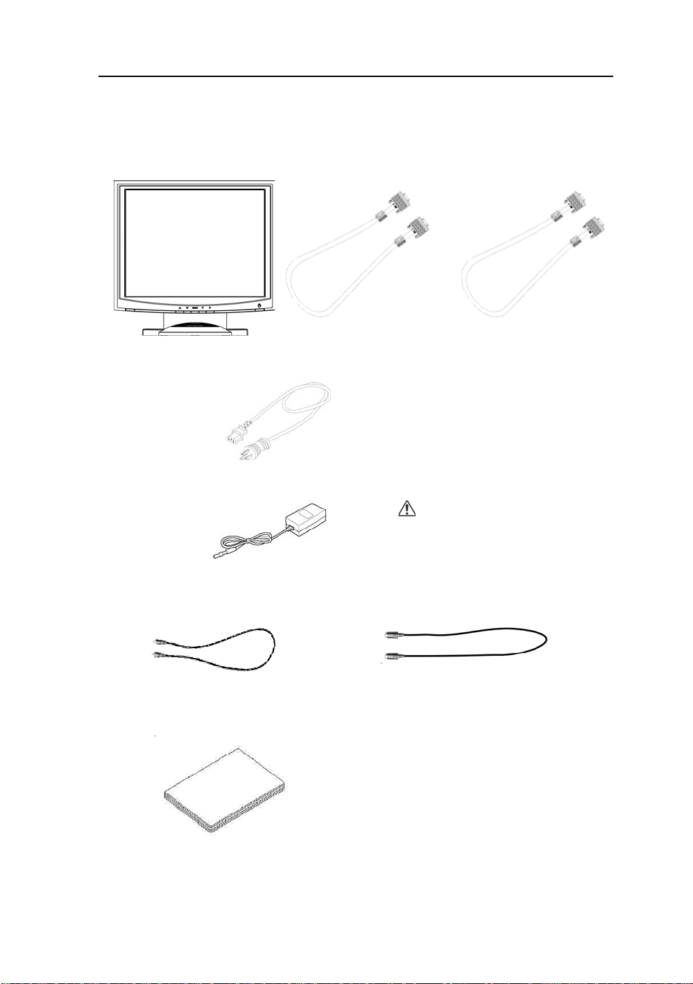
Please check the following items are present when you unpack the box, and save the packing
materials in case you will need to ship or transport the monitor in future.
• AMVX1908 LCD Monitor and two video cable (1) VGA HDDB15 cable (1) DVI-D cable
• AC Power cord
• AC-Adapter
• Composite V ideo BNC Jack Cable and Super V ideo Cable
• User Manual
CAUTION
Manufacturer : Ault Korea
Model No : MW116
Page 9
8 User’s Guide
W arnings and Cautions
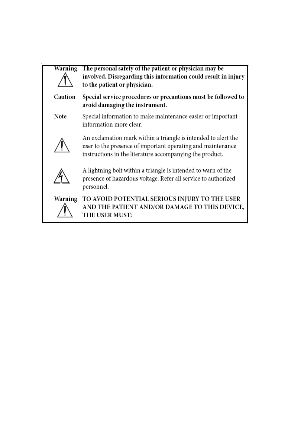
Please read this manual and follow its instructions carefully. The words warning, caution,
and note carry special meanings and should be carefully reviewed:
Warranty is void if any of these warnings ar e disregarded.
Ampronix accepts full responsibility for the effects on safety , reliability , and performance of
the equipment only if:
• Re-adjustments, modifications, and/or repairs are carried out exclusively by
Ampronix.
• The electrical installation of the relevant operating room complies with the
applicable IEC and CE requirements.
Warning Federal law (United S tates of America) restricts this device to use by ,
or on order of a physician.
The Ampronix AMVX1908 monitor has been tested under UL 60601-1 standard and UL
listed for Medical application.
Ampronix reserves the right to make improvements in the product(s) described herein.
Product(s), therefore, may not agree in detail to the published design or specifications. All
specifications are subject to change without notice. Please contact Ampronix directly or
phone your local Ampronix sales representative or agent for information on changes and
new products.
Page 10

AMVX1908 9
Warnings
1. Read the operating manual thoroughly and be familiar with its contents prior to using
this equipment.
2. Carefully unpack the unit and check if any damage occurred during shipment.
3. Should any solid object or liquid fall into the panel, unplug the unit and have it checked
by qualified personnel before operating it any further.
4. Uplug the unit if it is not to be used for an extended period of time. To disconnect the
cord, pull it out by the plug. Never pull the cord itself.
5. Be a qualified physician, having complete knowledge of the use of this equipment.
6. Test this equipment prior to a medical procedure. This monitor was fully tested at the
factory before shipment.
7. Avoid removing covers on control unit to avoid electric shock.
8. Attempt no internal repairs or adjustments not specifically detailed in this operating
manual.
9. Pay close attention to the care, cleaning instructions in this manual. A deviation may
cause damage (refer to the Cleaning section on page 14).
10. DO NOT STERILIZE MONITOR.
11. Read the entire instruction manual before assembling or connecting the camera.
12. Do not place the monitor or any other heavy object on the power cord. Damage to the
cable can cause fire or electirc shock.
13. Monitor with power supply is suitable for use in patient environment.
14. DO NOT stack more than 8 boxes high
This equipment has been tested and found to comply with the limits for medical devices in
IEC 601-1-2:2003. These limits are designed to provide reasonable protection against
harmful interference in a typical medical installation.
This equipment generates, uses and can radiate radio frequency energy and, if not installed
and used in accordance with the instructions, may cause harmful interference to other
devices in the vicinity. However, there is no guarantee that interference will not occur in a
particular installation. If this equipment does cause harmful interference to other devices,
which can be determined by turning the equipment off and on, the user is encouraged to try
to correct the interference by one or more of the following measures:
- Reorient or relocate the receiving device.
- Increase the separation between the equipment.
- Connect the equipment into an outlet on a circuit different from that to which the other
device(s) are connected.
- Consult the manufacturer or field service technician for help.
NOTICES TO USER
This device complies with Part 15 of the FCC Rules. Operation is subject to the following
two conditions:
(1) this device may not cause harmful interference, and (2) this device must accept any
interference received, including interference that may cause undesired operation.
FCC W ARNING
This equipement generates or uses radio frequency energy. Changes or modifications to this
equipment may cause harmful interference unless the modifications are expressly approved
in the instruction manual. The user could lose the authority to operate this equipment if an
unauthorized change or modification is made.
Page 11

10 User’s Guide
Cautions
1. The AC Adapter must be plugged into a Grounded power outlet.
2. Use only the proprietary AMVX1908 power supply for the AMVX1908 monitor . Make a
proper connection by ensuring that the shrink tubing completely secures the connection
between the DC power cord and the extension cord.
3. Turn power off when unit is not in use.
4. Never operate the unit right after having transported from a cold location directly to a
warm location.
5. Do not expose the monitor to moisture or directly apply liquid cleaners directly to the
screen. Spray the cleaning solution into a soft cloth and clean gently.
6. Handle the monitor with care. Do not strike or scratch the screen.
7. Do not block the monitor cooling vents. The monitor is cooled by natural convection and
has no fan.
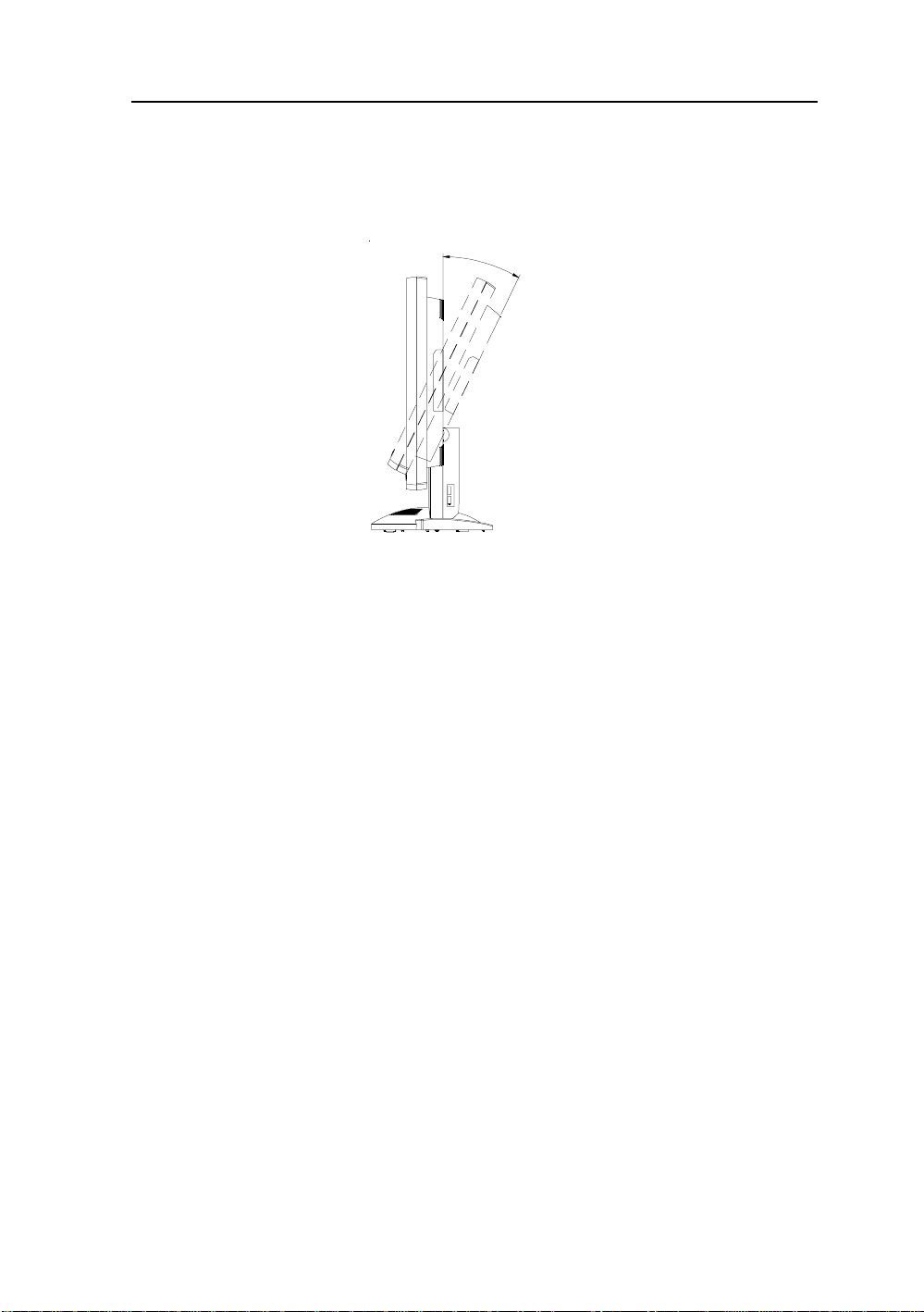
8. Do not force the monitor past 28 degrees of vertical when adjusting the screen position.
(For monitors equipped with stands only.)
9. Remove the power module and connection when transporting the unit.
10. Save the original carton and associated packing material. They will be useful should you
have to transport or ship the unit.
11. Allow adequate air circulation to prevent internal heat buildup.
12. Do not place the unit on surfaces (rugs, blankets, etc.) or near materials (curtains,
draperies) that may block the ventilation slots.
13. Do not install the unit near sunlight, excessive dust, mechanical vibration or shock.
14. The unit is designed for operation in a horizontal position. Never operate the unit in a
vertical position.
15. Keep the unit away from equipment with strong magnets (i.e. a large loudspeaker .)
16. Do not expose the monitor to moisture or excessive dust.
17. Equipment with SIP/SOP connectors should either comply with IEC 60601-1 and/or IEC
60601-1-1 harmonized national standard or the combination should be evaluated. Do not
touch the patient with signal input or output connectors.
18. Use only a hospital grade power supply cord.
19. This equipment generates, uses, and can radiate radio frequency energy. If not installed
correctly and or not used in accordance with these instructions, it may cause harmful
interference with other devices. This may be determined by turning the equipment off and
on. The user is encouraged to try to correct the interference through one or more of the
following measures:
• Reorient or relocate the receiving device.
• Increase the separation distance between the equipment.
• Connect the equipment to an outlet on a circuit different from that to which the other
device(s) are connected.
• Consult the manufacturer or field service technican for help.
20. Grounding reliability can only be achieved when the equipment is connected to an
equipment receptacle labeled “Hospital Only” or “Hospital Grade.”
Note To connect to an international power supply, use a an attachment plug appropriate
for the power outlet.
Note Refer to the “Electromagnetic Compatibility” (EMC) section of this manual to
ensure EMC. The AMVX1908 must be installed and operated according to the EMC
information provided in this manual.
Page 12
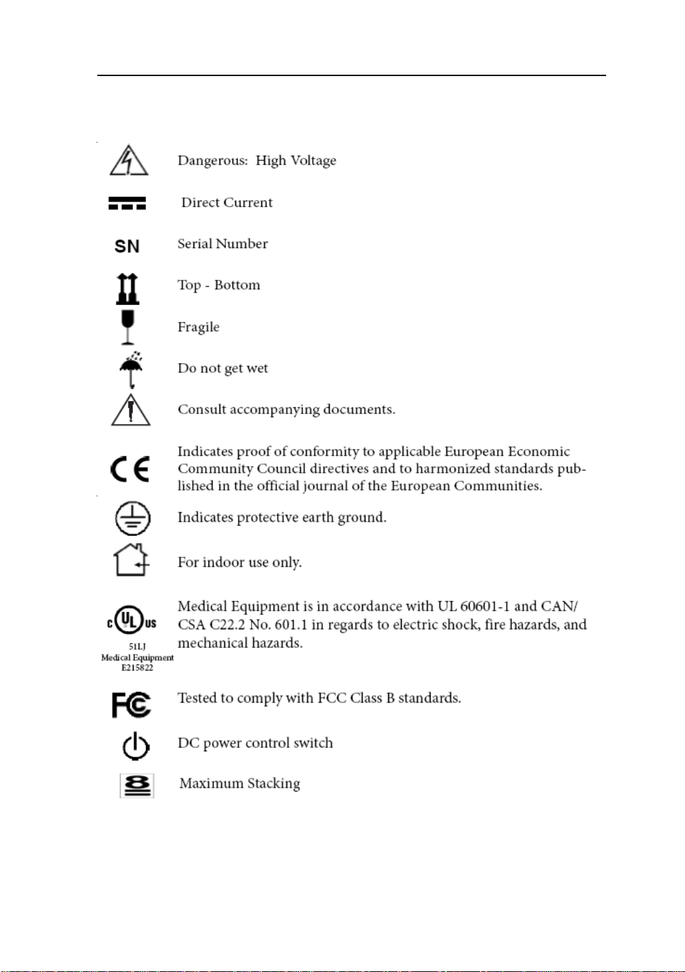
Symbol Definitions
AMVX1908 11
IPX1 Degrees of protection against the ingress of water.
Page 13

12 User’s Guide
EU Declaration of Conformity for Medical Applications
A Declaration of Conformity has been filed for this product. A sample of this
document may be found in the addendum which accompanied this manual. For a
copy of the Declaration of Conformity document, please contact Ampronix and
request for AMVX1908 DOC.
Prepare for Unpack
Before you unpack your monitor, prepare a suitable workspace. Y ou need a stable
and level surface near a grounded wall outlet in an area which is relatively free of
glare from sunlight or other sources of bright light. The monitor is cooled by natural
convection (it has no fan).
For optimum performance, do not block the cooling vents.
While unpacking the monitor, inspect it and other package contents for shipping
damage that could cause a fire or shock hazard. Immediately report any shipping
damage to the carrier or transportation company and contact customer service for
monitor in the future or in case of return.
After you unpack the monitor, make sure the following items are included
• Monitor with 1.5 meter(5ft)monitor-to computer video cable
• AC adapter with cable
CAUTION: AC Adapter must be plugged into Grounded a power outlet)
CAUTION : AC adapter
Manufacturer: Ault korea
Model No: MW116
• This operations manual
Note: Your system provider may offer alternative cords or cables
depending on the installation requirement and local geography issues.
Page 14
AMVX1908 13
SCREEN POSITION ADJUSTMENT
In order to optimize the best viewing position, you can adjust the tilt of the monitor by using
both of your hands to hold the edges of the monitor as shown in the figure below. The monitor can be adjusted to 28 degrees up as indicated by arrow below.
2
8
°
Page 15

14 User’s Guide
SAFETY PRECAUTION
• A void placing the monitor , or any other heavy object, on the power cord to prevent fire or
electrical shock from damage to the power cord.
• Do not expose the monitor to rain, excessive moisture, or dust to avoid fire or shock hazard.
• Do not cover the slots or openings of the monitor for proper heat dissipation. Always put
the monitor in a place where there is adequate ventilation.
• Avoid placing the monitor against a bright background or where sunlight or other light
sources may reflect on the area of the monitor. Place the monitor just below eye level.
• Handle with care when transporting the monitor.
• Refrain from giving the shock or scratch to the screen, as screen is fragile.
CLEANING YOUR MONITOR
No specific liquid or chemical necessary when cleaning this LCD monitor
However, we suggest to clean the monitor with non-abrasive cloths and cleaning solutions
used in hospitals to clean similar equipment. We recommend using 70% Isopropyl alcohol
for the screen surface and warm water and a mild detergent for all other surfaces. Other
acceptable cleaning agents are listed below:
• 70% isopropyl alcohol
• 6% aqueous ammonia
• Cidex (2.4% glutaraldehyde solution)
• Sodium Hypochlorite (bleach) 10%
• “Green soap” USP
• 0.5% Chlorhexidine in 70% isopropyl alcohol
• Ovation
• Formula 409
• Fantastic
• W ex Cide
T o clean the screen, do not spray liquid cleaners directly on to the unit. S tand away Form the
monitor and spray cleaning solution onto a cloth. Without applying excessive pressure,
clean the screen with the slightly dampened rag.
Page 16
AMVX1908 15
PRESET MODES
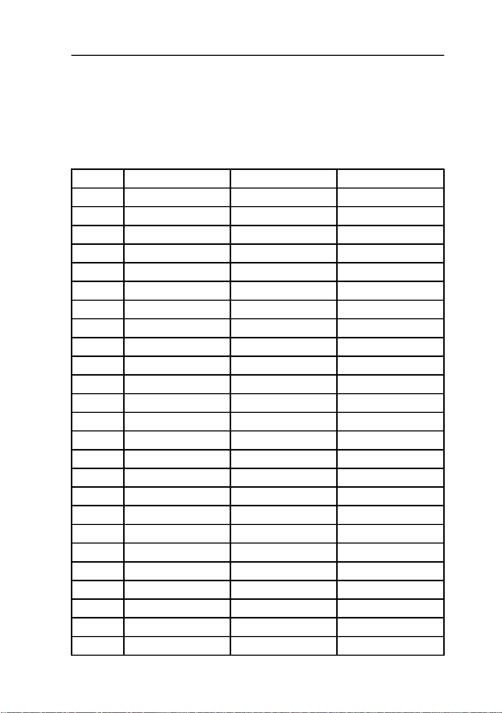
To reduce the need for adjustment for different modes, the monitor has default setting modes
that are most commonly used as given in the table below. If any of these display modes are
detected, the monitor automatically adjusts the picture size and centering. When none of the
mode is matched, the user can store their preferred modes in the user modes. The monitor is
capable of storing up to 7 user modes. The only condition to store as a user mode is the new
display information must have 1 KHz difference for horizontal frequency or 1 Hz for vertical
frequency or the sync signal polarities are different from the default modes.
M o de R e s olution (H x V) H. Fre q. (KHz) V. Fre q. (Hz)
1 640 x 350 31.5 70
2 640 x 350 37.9 85
3 640 x 400 31.5 70
4 640 x 400 37.9 85
5 720 x 350 31.5 70
6 720 x 400 31.5 70
7 7 20 x 400 37.9 85
8 640 x 480 31.5 60
9 640 x 480 37.9 72
10 640 x 480 37.5 75
11 640 x 480 43.3 85
12 800 x 600 35.1 56
13 800 x 600 37.9 60
14 800 x 600 48.1 72
15 800 x 600 46.9 75
16 800 x 600 53.7 85
17 1024 x 768 35.5 43
18 1024 x 768 48.4 60
19 1024 x 768 56.5 70
20 1024 x 768 60 75
21 1024 x 768 68.7 85
22 1152 x 864 67.5 75
23 1280 x 960 60 60
24 1280x1024 63.9 60
25 1280x1024 79 75
Page 17
16 User’s Guide
POWER MANAGEMENT FUNCTION
The monitor is equipped with the power management function which automatically reduce the
power consumption when not in use in three power level modes.
• Stand-by Mode
The monitor goes into stand-by mode when the horizontal sync signal is off for about 10
seconds. In this mode, the screen goes off and the power LED blinks for 1 seconds On and
1 second Off. The screen is displayed after the horizontal sync signal is restored.
• Suspend Mode
The monitor goes into suspend mode when the vertical sync signal is off for about 10
seconds. The power consumption during this is less than 8 W. In this mode, the screen
goes off and the power LED blinks for 1 seconds On and 1 second Off. The screen is
displayed after the vertical sync signal is restored.
• Off Mode
The monitor goes into power-off mode when the vertical and horizontal sync signals are
off for about 10 seconds. In this mode, the screen goes off and the power LED blinks for 1
seconds On and 1 second Off. The screen is displayed after the vertical and horizontal
sync signals are restored.
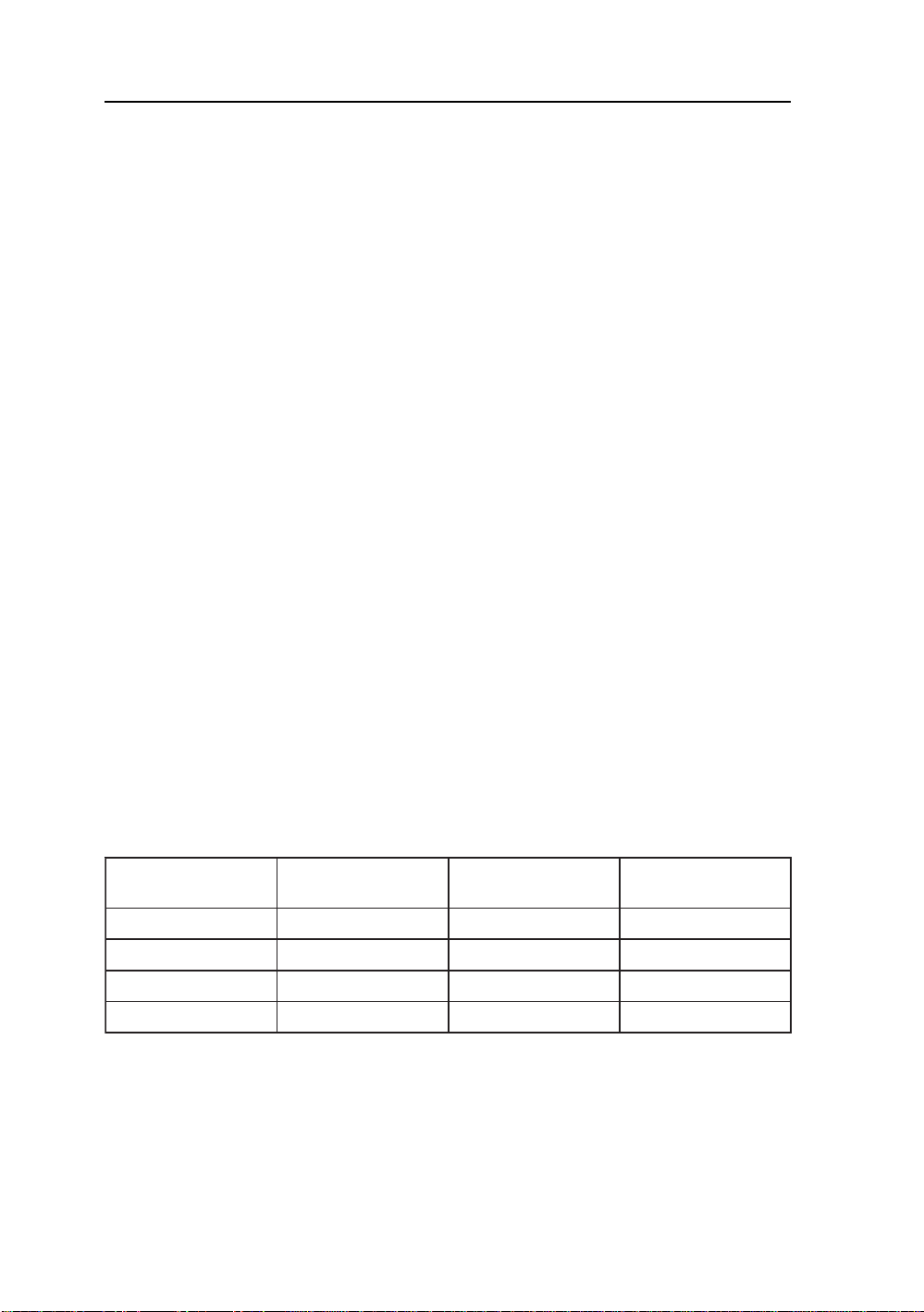
Power Management System
The AMVX1908 Medical Monitor complies with the VESA DPMS power management
proposal. The VESA DPMS proposal provides four phases of power-saving modes by
detecting the horizontal sync signal as shown in the table blow.
edoMrewoPtupnICD
)ylnorotinom(
nO.xamW53.xamW06neerGydaetS
ybdnatS.xamW5
dnepuS.xamW5.4.xamW6neerGgniknilB
ffO.xamW5.4.xamW6neerGgniknilB
.4.xamW6neerGgniknilB
rewoptupnICA
)retpadaCA.lcnI(
sutatSDEL
When the monitor is power saving mode or detects an incorrect timing, the screen will be
blank and power LED indicator will blink.
Page 18

AMVX1908 17
DDC
T o make your installation easier , the monitor is able to Plug and Play with your system if your
system also supports DDC protocol. The DDC (Display Data Channel) is a communication
protocol through which the monitor automatically informs the host system about its
capabilities, for example, supported resolutions and corresponding timing. The monitor
supports DDC1 and DDC2B standard.
INSTALLATION
To install the monitor to your host system, please follow the steps as given below:
Steps
1 . Use the VGA cable that provides D-SUB 15-pin connector and connect to the
15-pin connector on the VGA controller card.
2 . Connect the DC power to the DC power connector on the monitor.
3. Connect one end of AC power cord into the AC Adapter and the other end to AC
power outlet.
4. Then turn the computer on and then the monitor.
5. If the monitor still does not function properly, please refer to the troubleshooting section
to diagnose the problem.
CONNECTING the POWER CORD
* Check first to make sure that the power cord you use is the correct type required for your area.
* This monitor has an universal AC adapter that allows operation in either AC 100 - 240 Vac
voltage area. No user-adjustment is required.
* Plug one end of the power cord to the AC adapter, plug another end to a proper AC outlet.
The cord set should have the appropriate safety approvals for the country in which the equipment
will be installed and marked HAR.
For 120 volt Applications, use only UL Listed deachable power cord with NEMA configuration
5-15P type (parallel blades) plug cap. For 240 volt applications use only UL Listed Detachable
power supply cord with NEMA configuration 6-15P type (tandem blades) plug cap.
Page 19
18 User’s Guide
Display for Video and Image Playback
Explains how to use our AMVX1908 to play VCR, view television, video game, or digital camera
images. It also show you how to connect video and other types of video equipment to the
display.
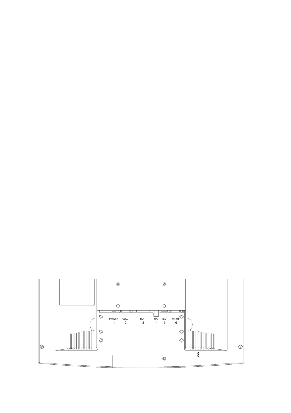
Connecting with Video Equipment
You can connect many types of video equipment to the display. The equipment must have
either Super video (S-video) ports or Composite video ports. To install the monitor to your
video equipment, please follow the steps as given below:
Steps
1 . Make sure the video equipment has a Super video (S-video) or a Composite video connector.
2. Turn off the computer, display, and video equipment before any types of connection.
3. For composite video, plug one end of a BNC cable into the video out port on the video
equipment then connect the other end to the monitor video input port.
4 . For S-video, plug one end of the S-video cable into the video out port on the video equipment
then connect the other end to the monitor S-video input port.
5. Connect the DC power to the DC power connector on the monitor.
6. Connect one end of AC power cord into the AC Adapter and the other end to AC
power outlet.
7. Then turn the video equipment on and then the monitor.
Connecting to a Television Signal
The display doesn’t have a tuner . To view television on the display, you need to use either the
VCR or TV tuner card in your computer to change channels.
Video and Sound
This monitor doesn’t have speakers for sound. If you’re using the display to play a video or
view television images, you need to connect the speakers to your television or video equipment
for sound.
Page 20
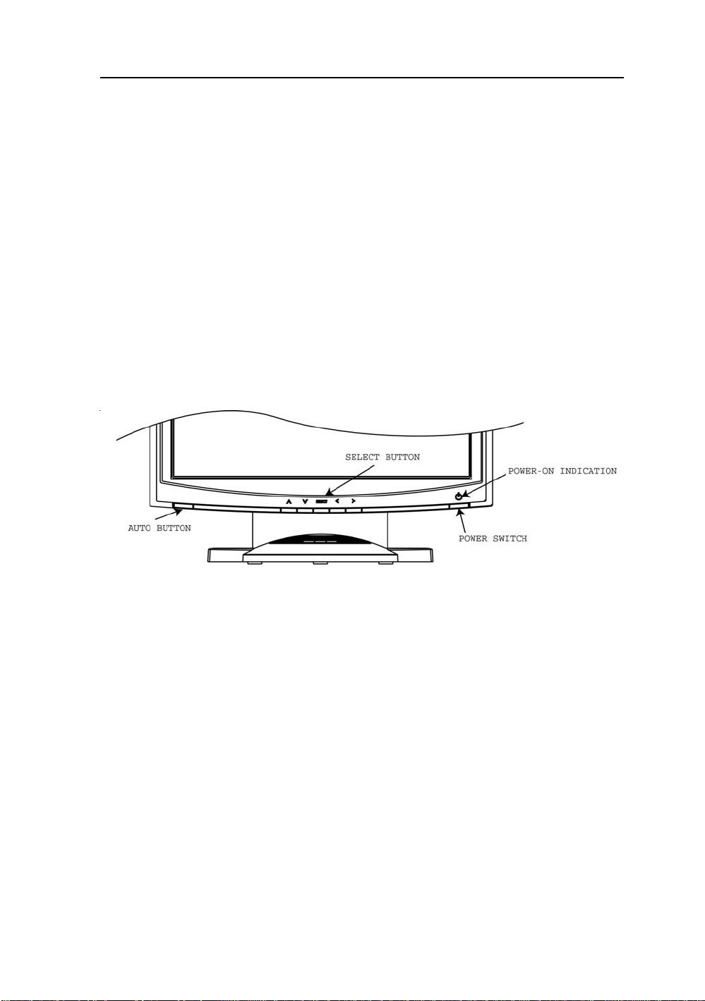
AMVX1908 19
USER CONTROLS
Front Panel Controls
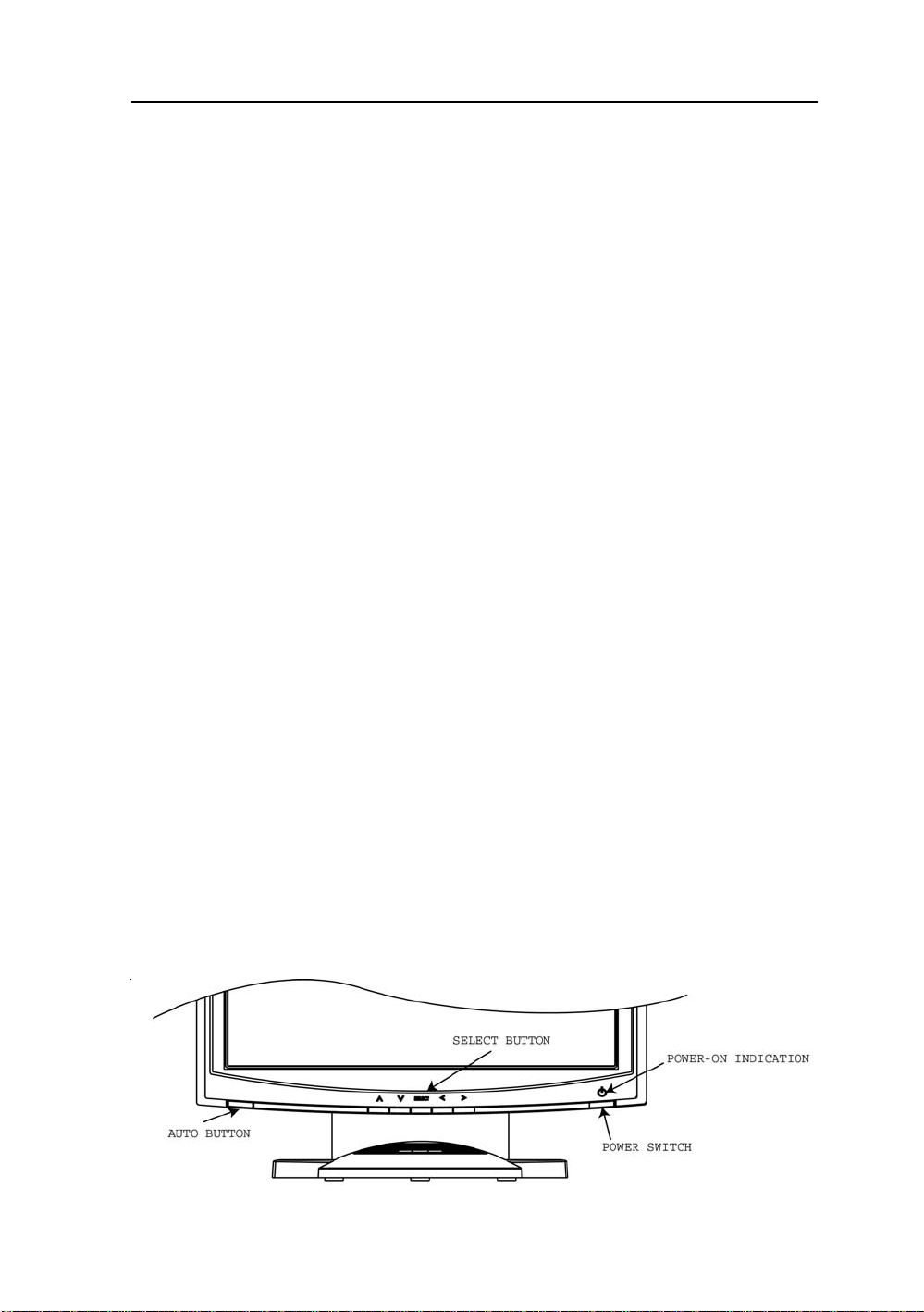
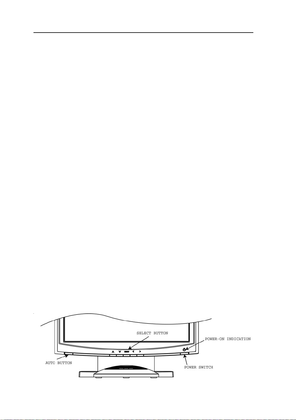
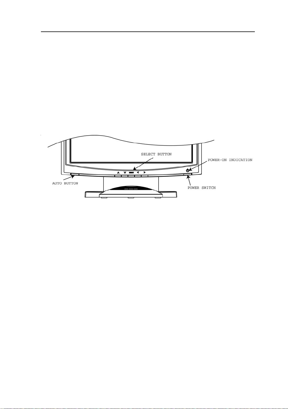
1. Power LED: Lights up to indicate the power is turned ON.
2. Power Switch: To turn ON or OFF the power.
3 . Up : To enter OSD menu then can use as moving forward in the OSD menu.
4. Down: To move backward in the OSD menu.
5. Select: Switch PC display to Video display and vice versa by one touch when OSD menu is not
activated.
Enter a sub menu or select a menu item.
6. Left: To increase the value of the parameter in the OSD you have selected for adjustment.
To increase the brightness directly when OSD menu is not activated.
7. Right: To decrease the value of the parameter in the OSD you have selected for adjustment.
To increase the brightness directly when OSD menu is not activated.
8. Auto Button: One touch Auto adjust (Hold 1 Sec.) or Exit OSD menu.
Standard OSD Operation
1. Press Up button to activate the OSD.
2. Use Select Up or Down keys to move up or down through the menu. The parameter will be highlighted
wehn selected.
3. Then use + or - to increase or decrease the value of the parameter, or make selection between different
options.
4. To quit the OSD screen at any time during the operation, press Auto button. If no keys are pressed for a
time period, the OSD automatically disappears.
Page 21
20 User’s Guide
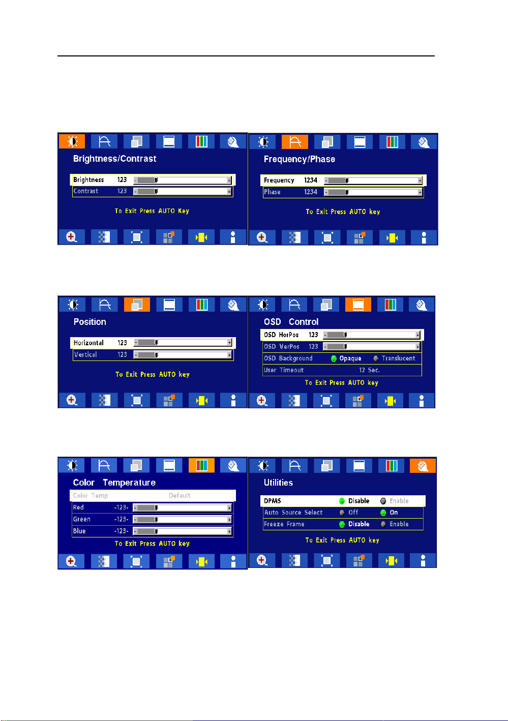
OSD Scren Basic Section (VGA)
For OSD display, push “Up”. For selecting Icon, push “Up” or
“Down”
Push “Up” or “Down” button to select between
“Brightness” or “Contrast” then push “Select”
Use “Left” or “Right” button to adjust
Push “Up” or “Down” button to select between
“Horizontal” or “V ertical” then push “Select”
Use “Left” or “Right” button to adjust
Push “Up” or “Down” button to select between
“Frequency” or “Phase” then push “Select”
Use “Left” or “Right” button to adjust
Push “Up” or “Down” button to select between “OSD
Hor. Pos.”, “OSD Ver. Pos.”, “OSD Background”, or
“User Timeout” then push “Select”
Use “Left” or “Right” button to adjust
Push “Left” or “Right” to select Color Temp between
“Default”, “System 1”, “System 2”, “System 3”, or
“System 4” then push “Select”
If “System 1, 2, 3 or 4” were slected, push “Up” or
“Down” button to select between “Red”, “Green”, or
“Blue” then push “Select”
Use “Left” or “Right” button to adjust
Push “Up” or “Down” button to select between
“DPMS”, “Auto Source Select”, or “Freeze Frame”
then push “Select” Use “Left” or “Right” button to
adjust
Page 22
AMVX1908 21
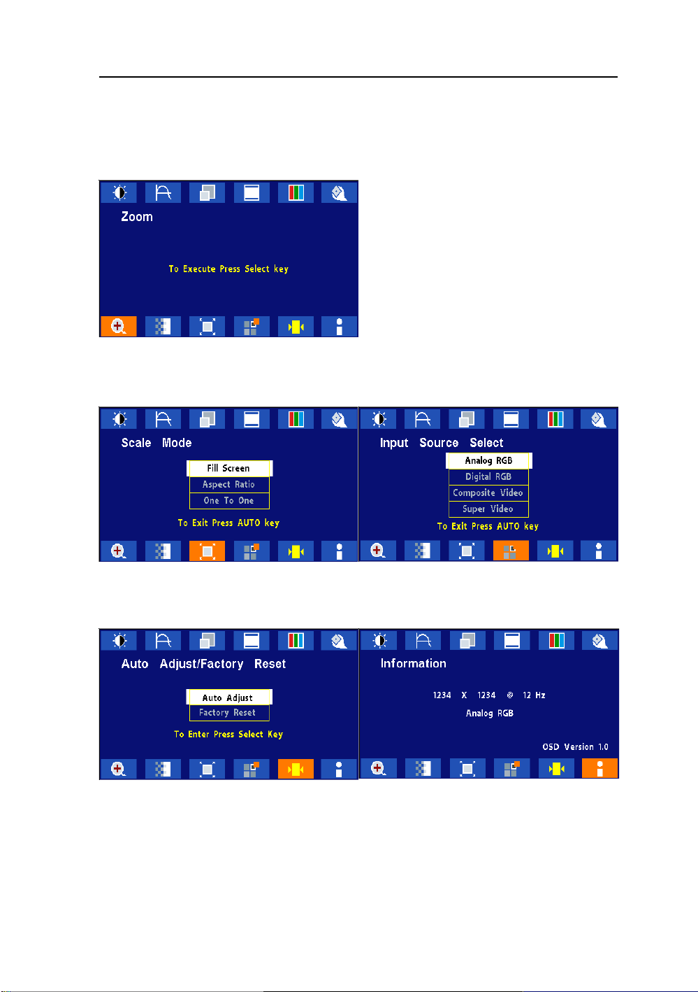
OSD Scren Basic Section (VGA)
For OSD display, push “Up”. For selecting Icon, push “Up” or
“Down”
Push the select button to execute the Zoom
function
Push the select button
Use “Left” or “Right” button to adjust
Push the select button to execute the Auto
Setup function or Push the select button to
execute Recall Factory Default
Push “Up” or “Down” button to select between
“Analog RGB”, “Digital RGB”, “Composite Video” or
“Super Video”
Use “Left” or “Right” to choose the correct mode then
push “Select” button
Push the select button to execute Information
Page 23
22 User’s Guide
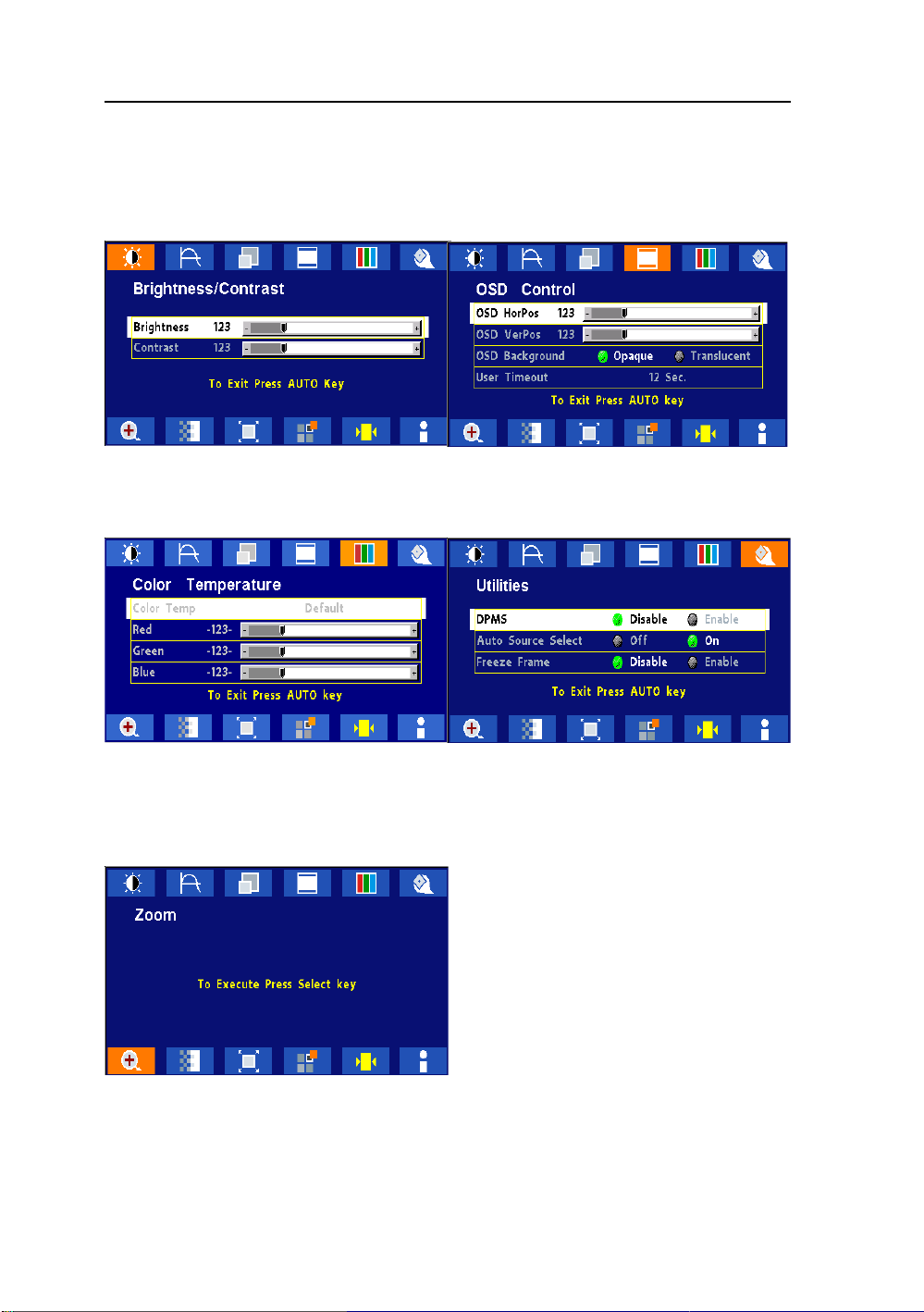
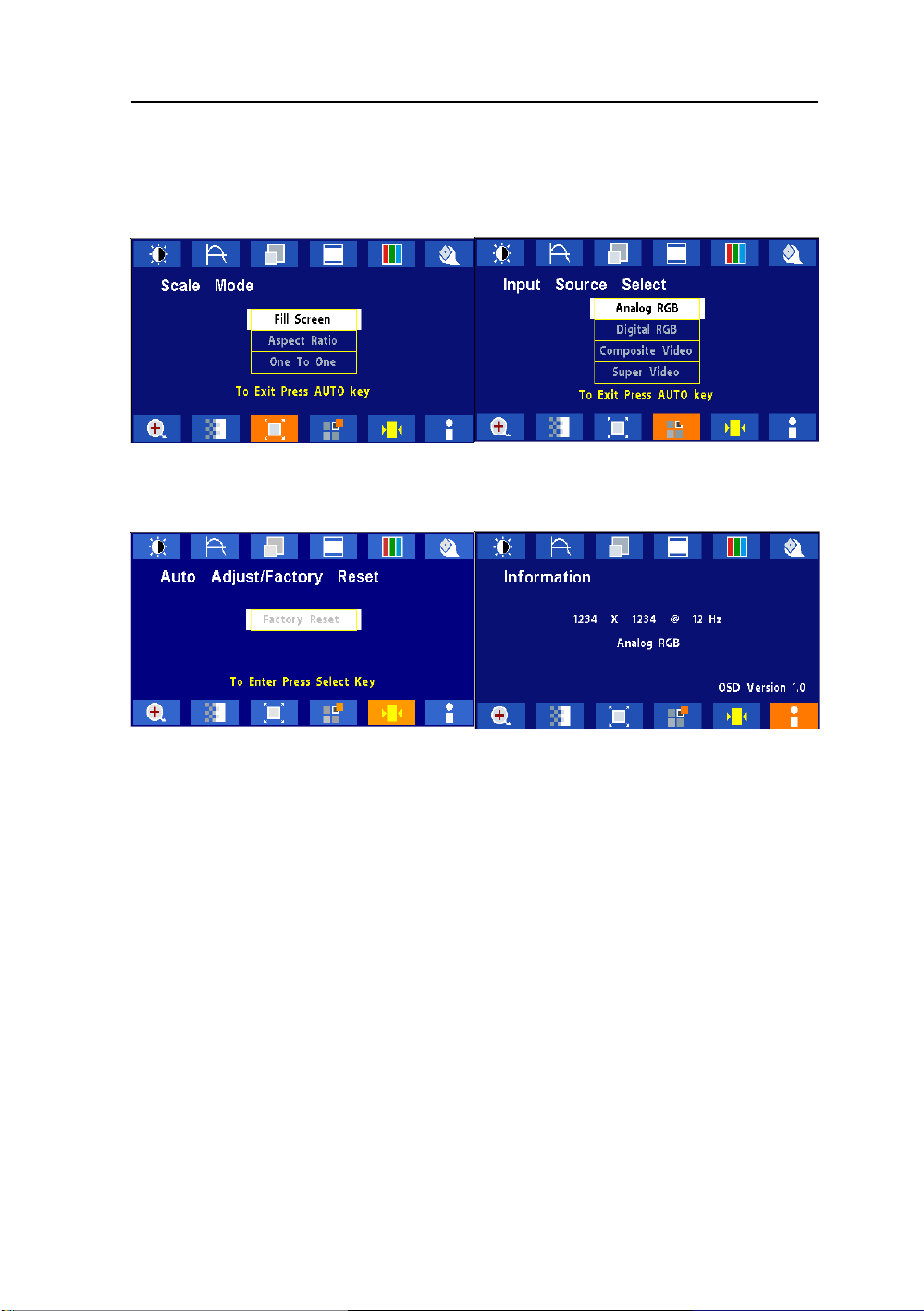
OSD Scren Basic Section (DVI)
For OSD display, push “Up”. For selecting Icon, push “Up” or
“Down”
Push “Up” or “Down” button to select between
“Brightness” or “Contrast” then push “Select”
Use “Left” or “Right” button to adjust
Push “Left” or “Right” to select Color Temp between
“Default”, “System 1”, “System 2”, “System 3”, or
“System 4” then push “Select”
If “System 1, 2, 3 or 4” were slected, push “Up” or
“Down” button to select between “Red”, “Green”, or
“Blue” then push “Select”
Use “Left” or “Right” button to adjust
Push “Up” or “Down” button to select between “OSD
Hor. Pos.”, “OSD Ver. Pos.”, “OSD Background”, or
“User Timeout” then push “Select”
Use “Left” or “Right” button to adjust
Push “Up” or “Down” button to select between
“DPMS”, “Auto Source Select”, or “Freeze Frame”
then push “Select” Use “Left” or “Right” button to
adjust
Push the select button to execute the Zoom
function
Page 24
AMVX1908 23
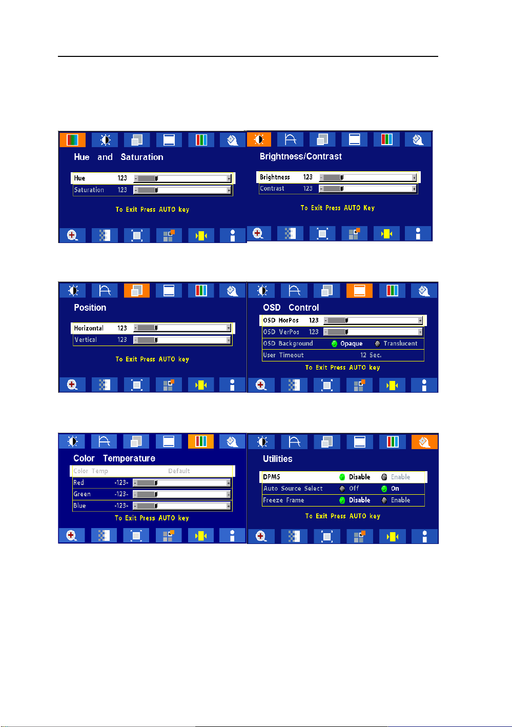
OSD Scren Basic Section (DVI)
For OSD display, push “Up”. For selecting Icon, push “Up” or
“Down”
Push “Up” or “Down” button to select between
Push the select button
Use “Left” or “Right” button to adjust
“Analog RGB”, “Digital RGB”, “Composite Video” or
“Super Video”
Use “Left” or “Right” to choose the correct mode then
push “Select” button
Push the select button to execute Recall
Factory Default
Push the select button to execute Information
Page 25
24 User’s Guide
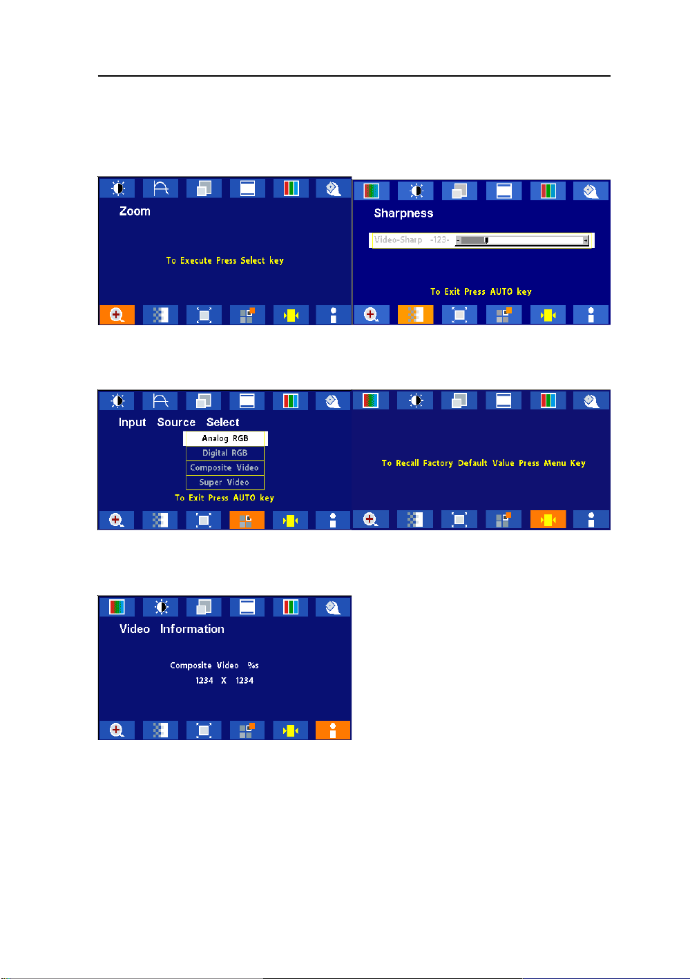
OSD Scren Basic Section (C-V ideo or S-V ideo)
For OSD display, push “Up”. For selecting Icon, push “Up” or
“Down”
Push “Select” button then “Up” or “Down”
Push “Left” or “Right” button to adjust
Push “Up” or “Down” button to select between
“Horizontal” or “V ertical” then push “Select”
Use “Left” or “Right” button to adjust
Push “Up” or “Down” button to select between
“Brightness” or “Contrast” then push “Select”
Use “Left” or “Right” button to adjust
Push “Up” or “Down” button to select between “OSD
Hor. Pos.”, “OSD Ver. Pos.”, “OSD Background”, or
“User Timeout” then push “Select”
Use “Left” or “Right” button to adjust
Push “Left” or “Right” to select Color Temp
between “5000”, “6500”, 7300”, “9500”, or “User”
then push “Select”
If “User” were slected, push “Up” or “Down” button
to select between “Red”, “Green”, or “Blue” then
push “Select”
Use “Left” or “Right” button to adjust
Push “Up” or “Down” button to select between
“DPMS”, “Auto Source Select”, “Freeze Frame”, or
“ADC Calibration” then push “Select”
Use “Left” or “Right” button to adjust
Page 26
AMVX1908 25
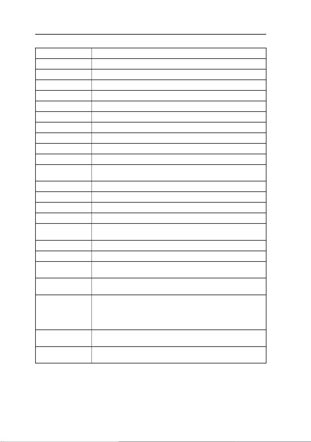
OSD Scren Basic Section (C-V ideo or S-V ideo)
For OSD display, push “Up”. For selecting Icon, push “Up” or
“Down”
Push the select button
Use “Left” or “Right” button to adjust
Push the select button
Use “Left” or “Right” button to adjust
Push the select button
Use “Left” or “Right” button to adjust
Push the select button to execute Recall
Factory Default
Push the select button to execute Information
Page 27
26 User’s Guide
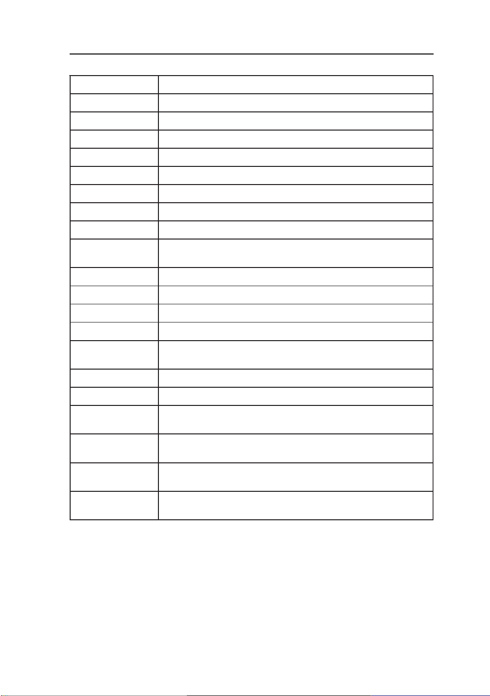
OSD Function Description (Under Analog Display)
metInoitpircseDnoitcnuF
ssenthgirB.ssenthgirbehtesaercedroesaercnioT
tsartnoC.tsartnocehtesaercedroesaercn
ycneuqerF.)kcolctod(ycneuqerftsujdaoT
esahP.)esahp-kcolc(esahptsujdaoT
latnoziroH.thgirrotfelneercsehte
lacitreV.drawnwodrodrawpuneercsehtevomoT
soProHDSO.thgirrotfelunemDSOevomoT
soPreVDSO.drawnwodrodrawp
dnuorgkcaBDSO.tneculsnarTroeuqapOneewtebesoohC
tuoemiTresU.emitgniraeppaneercsDSOteS
loC ro3metsyS,2metsyS,1metsyS,tluaufeDneewtebesoohC
deR.deRecnalaB
eulB.
pmeTro
neerG.neerGecnalaB
SMPD.SMPDelbasiDroelbanE
ecruoSotuA
tceleS
emarFezeerFemarfez
ioT
vomoT
uunemDSOevomoT
.pmetroloc4metsyS
eulBecnalaB
eerfelbasiDroelbanE
noitcelesecruosotuaelbasidroelbanE
mooZnoitcnufni-moozelbanE
edoMelacS enoro,oitartcepsa,neercsllifneewtebedomelacsesooh
ecruoStupnI
tceleS
otuA -H,noitisoP-VtsujdayllacitamotualliwtsujdA-otuAehT
tsujdA
yrotcaFllaceR
tluafeD
noitamofnI tupnidna,etarhserfer,noitulosernonoitamrofniyalps
C
enoot
oedivrepusro,oedivetisopmoc
,kcolC,noitisoP
noCdna,esahP-kcolC
om
.tluafedyrotcafotteS
iD
.edom
.)tsujdAotuArofksidytiliturotin
,BGRlatigid,BGRgolananeewtebecruostupniesoohC
5tuobasekatssecorpelohweht,tsart
DCLdehcattaehtnielifnrettaptsetehtesuesaelP(.sdnoces
Page 28
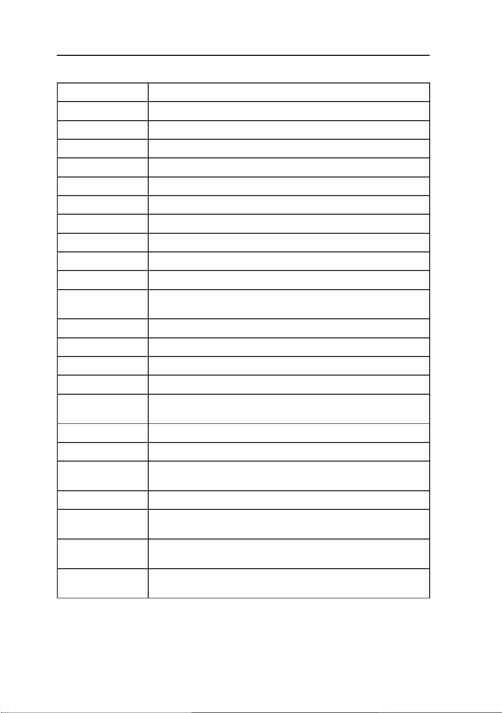
OSD Function Description (Under Digital Display)
metInoitpircseDnoitcnuF
ssenthgirB.ssenthgirbehtesaercedroesaercnioT
AMVX1908 27
tsartnoC.tsartnocehtesaercedroesaercn
latnoziroH.thgirrotfelneercsehtevomoT
lacitreV.drawnwodrodrawpuneercsehtevomoT
soProHDSO.thgirrotfelune
soPreVDSO.drawnwodrodrawpuunemDSOevomoT
dnuorgkcaBDSO.tneculsnarTroeuqapOneewtebesoohC
esU.emitgniraeppaneercsDSOteS
deR.deRecnalaB
neerG.neerGecnalaB
eulB.eulBecnalaB
SMPD.SMPDelbasiDroelbanE
tceleS
mooZnoitcnufni-moozelbanE
tuoemiTr
pmeTroloC ro3metsyS,2metsyS,1metsyS,tluaufeDneewtebesoohC
ecruoSotuA
emarFezeerFemarfezeerfelbasiDroelbanE
ioT
mDSOevomoT
.pmetroloc4metsyS
uaelbasidroelbanE
noitcelesecruosot
edoMelacS enoro,oitartcep
enoot
ecruoStupnI
tceleS
yrotcaFllaceR
tluafeD
noitamofnI tupnidna,etarhserfer,no
.edom
.tluafedyrotcafotteS
itulosernonoitamrofniyalpsiD
sa,neercsllifneewtebedomelacsesoohC
,BGRlatigid,BGRgolananeewtebecruostupniesoohC
oedivrepusro,oedivetisopmoc
Page 29
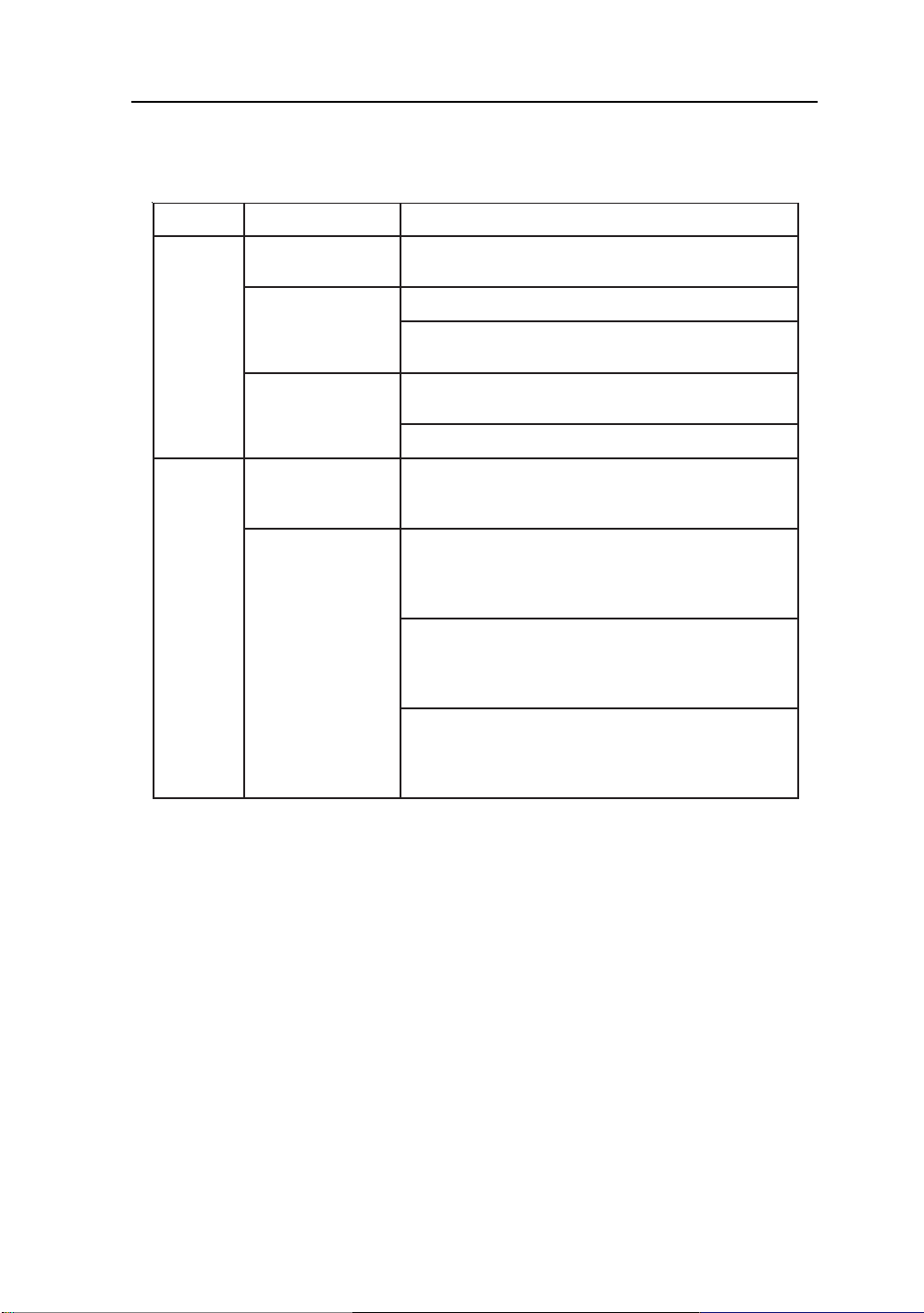
28 User’s Guide
OSD Function Description (Under C-Video or S-Video Display)
metInoitpircseDnoitcnuF
euH.leveleuhehtesaercedroesaercnioT
noitarutaS.levelnoitarutasehtesaercedroesaercnioT
ssenthgirB.ssenthgirbehtesaercedroesaercnioT
tsartnoC.tsartnocehtesaercedroesaercnioT
latnoziroH.thgirr
lacitreV.drawnwodrodrawpuneercsehtevomoT
soProHDSO.thgirrotfelunemDSOevomoT
soPreVDSO.drawnwodrodrawpuunemDSOevomoT
dnuorgkcaBDSO.tneculsnarTroeuqapOneewtebesoohC
tuoemiTresU.emitgniraeppaneercsDSOteS
pmeTroloC ro3metsyS,2metsyS,1metsyS,tluaufeDneewtebesoohC
deR.deRecnalaB
neerG.neerGecnalaB
eulB.eulBecnalaB
SMPD.SMPDelbasiDroelbanE
ecruoSotuA
tceleS
em
arFezeerF.emarfezeerfelbasiDroelbanE
mooZ.noitcnufni-moozelbanE
edoMelacSoediV ,edomelacs3:4,lamronneewtebedomelacsoedivesoohC
otfelneercsehtevomoT
.pmetroloc4metsyS
noitcelesecruosotuaelbasidroelbanE
.edomelacs9:61ro
ssenprahSoediV.ssenprahsoedivehtesaercedroesaercnioT
ecruoStupnI
tce
leS
yrotcaFllaceR
tluafeD
noitamofnI tupnidna,etarhserfer,noitulosernonoitamrofniyalpsiD
.edom
.tluafedyrotcafotteS
oedivrepusro,oedivetisopmoc
,BGRlatigid,BGRgolananeewtebecruostupniesoohC
Page 30
AMVX1908 29
TROUBLESHOOTING
Before sending your LCD monitor for servicing, please check the troubleshooting list below
to see if you can self-diagnose the problem.
smelborPsutatStnerruCydemeR
NODEL
FFODEL
oN
erutciP
gniknil
BDEL
siyalpsiD
lamronbA
erutciP
alpsid
niegralootro
ezisy
•
•
•
•
hC
•
erutciPelbatsnU
•
•
retnec,gnissim
llamsootro,tfihs
•
•
nomdna
egami
uM
.rotinom
teserromumixam
.hctiwsrewopehtkcehC
ylreporpsidrocrewopCAfikcehC
.retpadaCAehtotdetcennoc
.rotinomfokcabehttadetcennoc
.gnimithserferlacitrevrehto
ottsartnocdnassenthgirbtsujda,DSOgnisU
.sgnittestluafedriehtot
ylreporpsielbaclangisoedivfikcehC
.NOsimetsysretupmocotrewopehtfikce
retpadascihpargfonoitacificepsehtfikcehC
ebyamhcihwecnailpmocnisiroti
.hctamsimycneuqerflangistupniehtgnisuac
yalpsidllitsfi,nottubputeSotuAgnisU
,KCOLCtsujdanehterutciplamronba
-VdnaNOITISOP-H,ESAHP-KCOLC
slangisdradnats-nonhtiwNOITISOP
.
neercs-llufgnissimfoesacni,DSOgnisU
ruoyninoituloserrehtotcelesesaelp,
ro)TN,89/59swodniW(metsySgnitarepO
gnitsujdaretfasdnoceswefaroftiawts
rognignahcerofebegamiehtfoeziseht
ehtFFOgnirewoprolangisehtgnitcennocsid
Page 31

30 User’s Guide
SPECIFICATION
8091XVMA
lenaPDCLenaPTFTroloChcni-91/mc84
epyTxirtaMevitcA
noituloseR )dednemmoceR(senil4201xstod0821
exiPmm492.0
hctiPl
roloCyalpsiDsrolocnoillim61
emiTesnopseRxamsm8.gvasm21
enoTroloCenot652otpU
retliFroloCepytepirtsl
gnihsiniFecaFdetaoCdraHeralG-itnA
elgnAgniweiV)01=>RC(V°871H°871
oediV latigiD)kniLlenaP(SDMT&BG
langiStupnI
cnyScnysdetarapesp-pV0.5~5.2
)golanA(ecnadepmItupnImhO57-oediV
cnySetisopmoCoediV-S,oediV-C
latigiD -BSMtib42lexipelgnis,reviecerSDMTlennahc3
nnacS
latnoziroHzHk8.97~74.13
lacitreV otpudnaedom867x4201tazH58otPU(zH58~05
H )mm103xmm673("9.11x"8.41
Vx
ssenthgirBxaM,2m/dc054
selacSyarGspets652otpU
oediV oediV-S,CSTN,IVDlatigiD,nip51-51DH
troplaireS9-BD232-SR
R
eW
snoitaluge
tenibaC
tnuoMeerF )D(hcni3x)H(hcni52.41x)W(hcni5.71
thgi
tnuoMeerF)gK3.7(.bl61
esaBtliT
ycneuqerFgni
eziSyalpsiD
oitaRtsartnoC.pyT1:0
rotcennoCtupnIlangiS
tnemnorivnEerutarepmeT
erutarepmeTgnitarepO)C°04-°01(F°401~°05
ytidimuHgnitarepO )noitasnednoctuohtiw(HR%
erusserPcirehpsomtAgnitarepOaPh0601~007
ecruoSrewoP
rotinoMyalpsiDV51CD
retpadA-CAV042~001CA
CMEdnaytefaS 1XPI,EC,2-1-10606NE,1-10606NE,1-10606LU
dnatSpotkseD )D(hcni5.9x)H(hcni8.71x)W(hcni5.71
dnatSpotkseD)gK6.8(.bl91
* All contents are subject to change without notice.
S
selacSyarG,oitdaRtsartnoC,ssenthgirB
09
om
acitrevBGR
Rgolanap-pV7.0
1xzHM561
mhOk1-cny
TFTBGRdengila
)4201x0821tazH57
57~03
hcuotenon,1XPIhtiwecnailpmocsirotinomehT(
)ylnoled
pU°82nwoD°0
Page 32

AMVX1908 31
51LJ
Medical Equipment
E215822
This monitor is intended for use in Health Care Facilities model AMVX1908
Equipment is not suitable for use in the presence of flammable anesthetic mixture
with air or with oxygen or nitrous oxide.
No user serviceable parts inside, ask qualified personnel when accessing inside.
For disposal of waste product, follow the requirement of local code.
Electrical input rating: 15V DC 6A
Classification
T ype of protection against electric shock: Class I Equipment.
Degree of protection against the ingress of water: IPX1
Mode of operation: Continuous
This monitor has been tested to comply with IEC/EN 60601-1, IEC/EN60601-1-2 and is
certified by UL to medical standard UL60601-1(UL/cUL Mark).
Because many medical offices are located in residential areas, this monitor, in addition to the
medical requirements, has also been tested and found to comply with the limits for FCC Class
B computing devices in a typically configured system. It is the system integrator or
configurer’s responsibility to test and ensure that the entire system complies with applicable
EMC laws.
Environmental conditions for transport and storage:
- Temperature range within -4° to 140° F (-20° to 60° C)
- Relative humidity range within 10% to 90%
- Atmospheric pressure range within 500 to 1060 hPa.
Page 33
32 User’s Guide
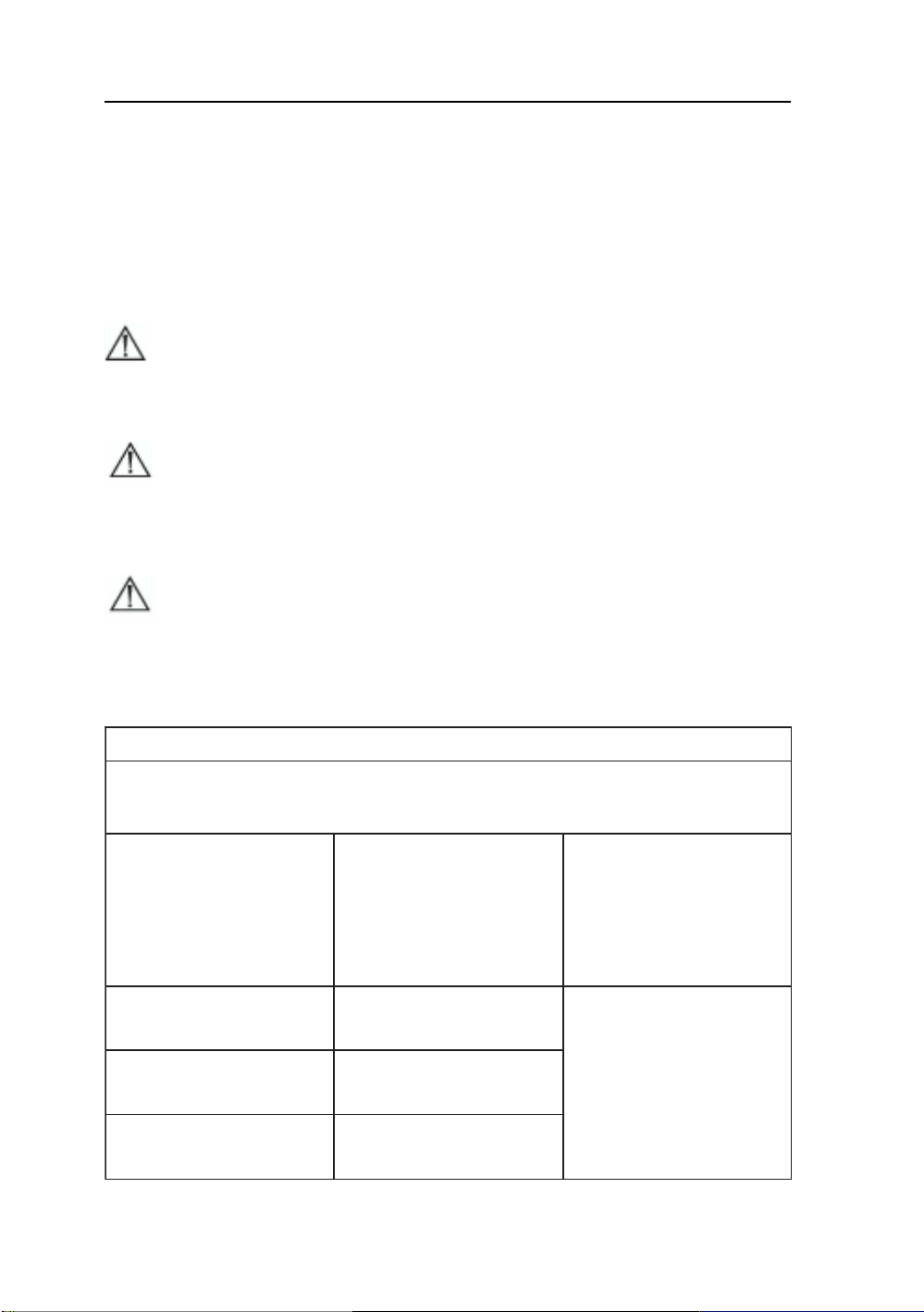
Electromagnetic Compatibility
Like other electrical medical equipment, the AMVX1908 requires special
precautions to ensure electromagnetic compatibility with other electrical medical
devices. To ensure electromagnetic compatibility (EMC), the AMVX1908 must be
installed and operated according to the EMC information provided in this manual.
Note The AMVX1908 has been designed and tested to comply with
IEC 60601-1-2:2001 requirements for EMC with other devices.
Caution Portable and mobile RF communications equipment may affect
the normal function of the AMVX1908.
Warning Do not use cables or accessories other than those provided
with the AMVX1908, as this may result in increased electromagnetic emissions
or decreased immunity to such emissions.
Warning If the AMVX1908 is used adjacent to or stacked with other
equipment, observe and verify normal operation of the AMVX1908 in the
configuration in which it will be used prior to using it in a surgical procedure.
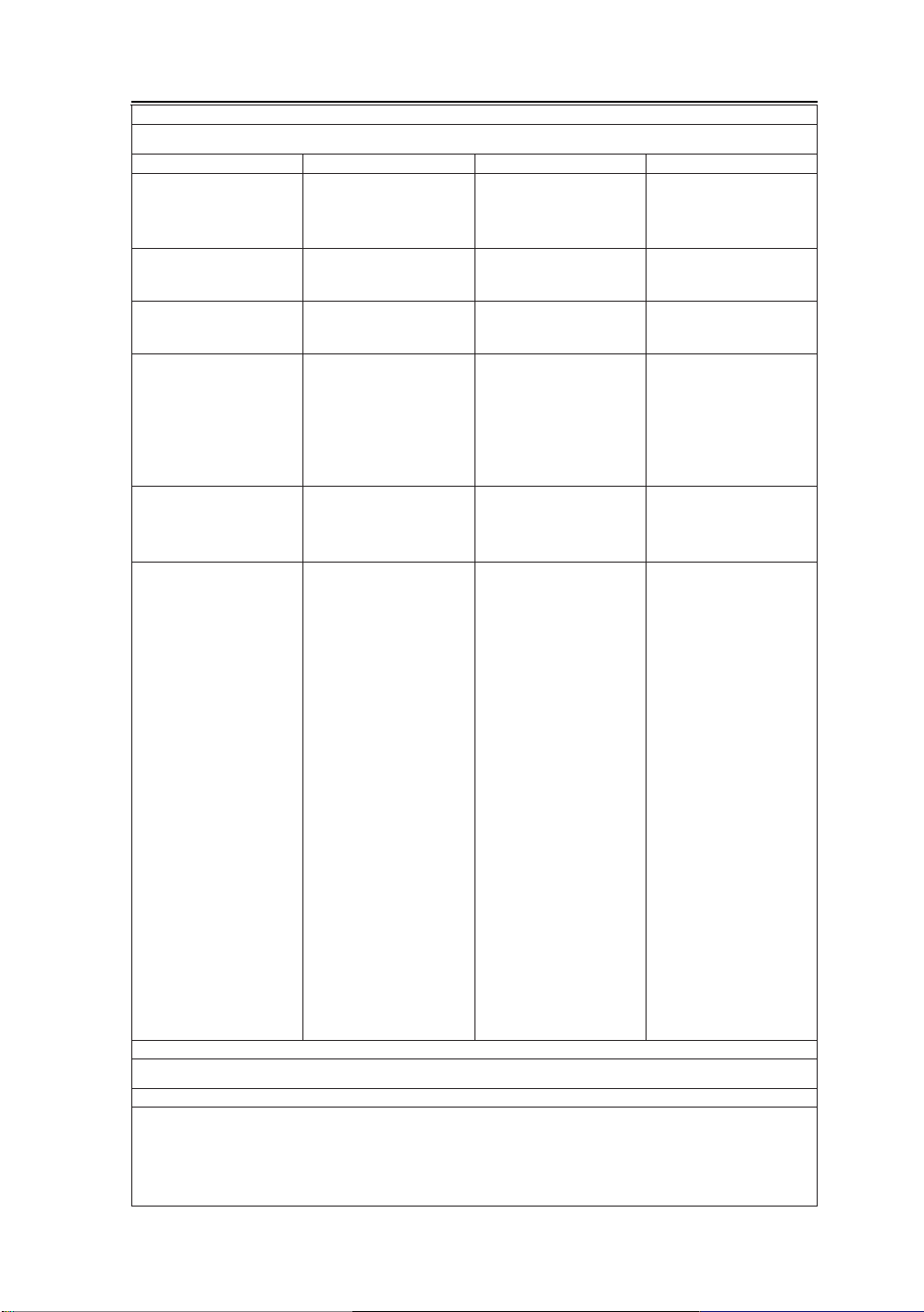
Consult the tables below for guidance in placing the AMVX1908.
snoissimEcitengamortcelE:noitaralceDs'rerutcafunaMdnaecnadiuG
eehtniesurofdednetnisi8091XVMA
vne
11RPSICsnoissimeFR1puorG
11RPSICsnoissimeFRBssalC
snoissimecinomraH
6CEI
2-3-0001
rekcilf/snoitautculFegatloV
3-3-00016CEIsnoissime
.tnemnori
radnawolyrevera
tiussi8091XVMA
AssalC
seilpmoC
sesoprup
.wolebdeificepstnemnorivnecitengamortcel
nahcusnidesusititahterusnedluohs8091XVMAforesuehtroremotsucehT
ygreneFRsesu8091XVMA
;noitcnuflanretnistirofylno
snoissimeFRsti,erofereht
tone
ynaesuacotylekil
ybraenniecnerefretni
.tnempiuqecinortcele
rofelba
,stnemhsilbatsellaniesu
citsemodgnidulcni
esohtdnastnemhsilbatse
ehtotdetcennocyltcerid
rew
opegatlov-wolcilbup
seilppustahtkrowtenylppus
citsemodrofdesusgnidliub
Page 34
fo
tseTytinummIleveLtseT10606CEIleveLecnailpmoCcitengamortcelE
2-4-00016CEI)DSE(
4-4-00016CEI
5-4-00016CEIegruSedomlaitnereffidVk1±
trohs,spidegatloV
dleifcitengam
8-4-00016CEI
FRdetcudnoC
6-4-00016CEI
FRdetaidaR
3-4-00016CEI
egrahcsiDcitatsortcelE
tsrub!tneisnarttsaflacirtcelE
egatlovdnasnoitpurretni
ylppusrewopnosnoitairav
11-4-00016CEIseniltupni
)zH06/05(ycneuqerfrewoP
tcat
nocVk6±
riaVk8±
nipid%59>(tU%5<
elcyc5.0
selcyc
selcyc52
.c
es5
m/A3A/N
rivnecitengamortceleehtniesurofdednetnisi8091XVMA
tcatnocVk6,4,2±
riaVk8,4,2±
s
enilylppusrewoprofVk2±
seniltuptuo/tupnirofVk1±
edomnommocVk2±
rof)tU
5rof)tUnipid%06(tU%04
rof)tUnipid%03(tU%07
rof)tUnipid%59>(tU%5<
zHM08otzHK051smrV3
zHG5.2otzHM08m/V3
dnuorgotenilVk2±
enilotenilVk1±
edoml
aitnereffidVk1,5.0±
edomnommocVk2,1,5.0±
rof)tUnipid%59>(tU%5<
elcyc5.0
selcyc
.ces5
V3
m/V3
5rof)tUnipid%06(tU%04
rof)tUnipid%03(tU%07
selcyc52
rof)tUnipid%59>(tU%5<
AMVX1908 33
ytinummIcitengamortcelE:noitaralceDs'rerutcafunaMdnaecnadiuG
.tnemnorivnenahcusnidesusititahterusnedluohs8091XVMA
euqerf-rewoP
norivne
dnaelbatroP
s
fo
dnemmocer
b
resuehtroremotsucehT.wolebdeificepstnemno
,doowebdluohssroolF
fI.elitcimarecro,etercnoc
htiwderevocerasroolf
eht,lairetamcitehtnys
taebdluohsytidimuhevitaler
.%03tsael
dluohsytilauqrewopsniaM
lacipytafotahteb
latipsohrolaicremmoc
.tnemnorivne
dluohsytilauqrewopsniaM
lacipytafotahteb
latipsohrolaicremmoc
.tn
emnorivne
dluohsytiliauqrewopsniaM
lacipytafotahteb
latipsohrolaicremmoc
foresuehtfI.tnemnorivne
er8091XVMA
seriuq
gnirudnoitarepodeunitnoc
ti,snoitpurretnisniamrewop
tahtdednemmocersi
derewopeb8091XVMA
rewopel
bitpurretninunamorf
.yrettabaroylppus
citengamycn
sleveltaebdluohssdleif
lacipytafocitsiretcarahc
lacipytaninoitacol
latipsohrolaicremmoc
.tnem
FRelibom
tnempiuqesnoitacinummoc
otresolcondesuebdluohs
8091XVMAehtfotrapyna
,selbacstignidulcni,metsy
dednemmocerehtnaht
ecnatsidnoitarapes
noitauqeehtmorfdetaluclac
ycneuqerfehtotelbacilppa
.rettimsnarteht
dednemmoceR
ecnatsiDnoitarapeS
p,71.1=d
zHM008otzHM08p,71.1=d
otzHM008p,33.2=d
zHG5.2
mumixamehtsiPerehw
e
htfognitarrewoptuptupo
)W(sttawnirettimsnart
rettimsnartehtotgnidrocca
ehtsiddnarerutcafunam
noitarapesde
.)m(sretemniecnatsid
FRdexifmorfshtgnertsdleiF
denimretedsa,srettimsnart
etiscitengamortcelenay
sselebdluohs,)a(yevrus
nilevelecnailpmocehtnaht
.)b(egnarycneuqerfhcae
ehtniruccoyamycnerefretnI
dekramt
nempiuqefoytiniciv
:lobmysgniwllofehthtiw
.seilppaegnarycneuqerfrehgiheht,zHM008dnazHM08tA:1ETON
.elpoepdna,stcejbo,serutcurtsmorfnoitcelfer
.leveltsetehtfonoitacilppaotroirpgatlovsniam.c.aehtsitU:3ETON
bafI.noitarepolamronyfirevotdevresboebdluohsmetsys8091XVMAeht,evobalevelecnailpmocFR
nitacolerrognitneircersahcus,yrassecenebyamserusaemlanoitidda,devresbosiecnamrofrep
.m/V3nahtsselebdluohsshtgnertsdleif,zHM08otzHk051egnarycneuqerfehtrevO)b(
dnanoit
prosbaybdetceffasinoitagaporpcitengamortcelE.snoitautisllaniylppatonyamsenilediugesehT:2ETON
dnaldnasenohpelet)sseldroc/ralullec(oidarrofsnoitatsesabsahcus,srettimsnartdexifmorfshtgnertsdleiF)a(
elibom
.ycaruccahtiwyllaciteroehtdetciderpebtonnoc,tsacdaorbVTdna,tsacdaorboidarMFdnaMA,oidarruetama,soidar
e
bdluohsyevrusetiscitengamortcelena,srettimsnartFRdexifoteudtnemnorivnecitengamortceleehtssessaoT
elbacilppaehtsdeecxedesusimetsys8091XVMAehthcihwninoitacolehtnihtgnertsdleifderusaemehtfI.deredisnoc
lamron
.tinu8091XVMAehtg
Page 35
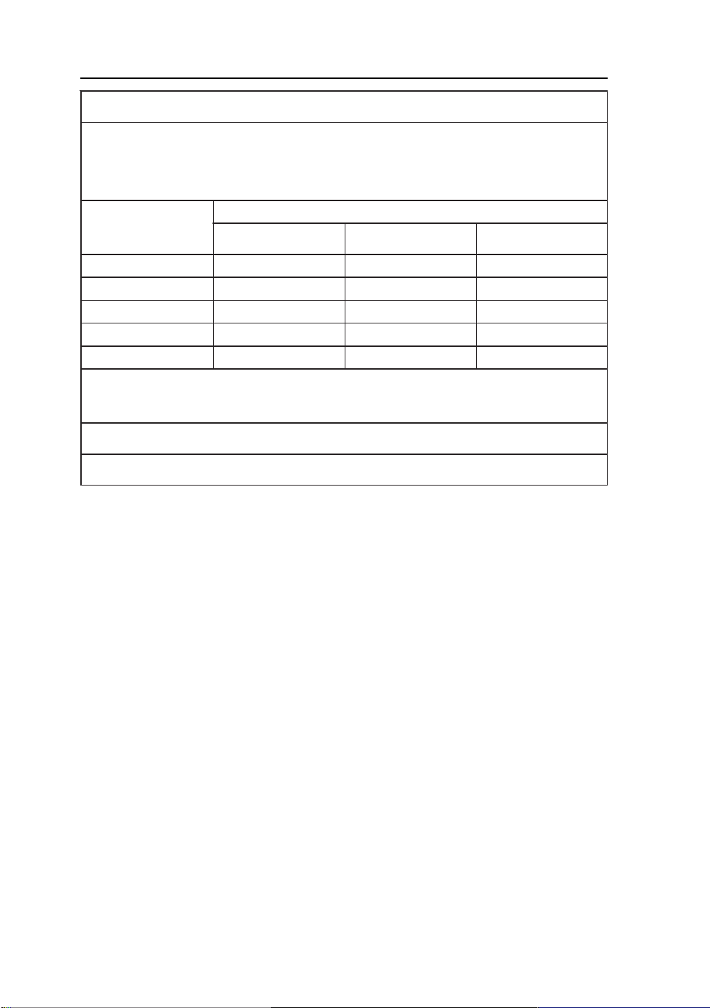
34 User’s Guide
neverp
mumixamdetaR
fo)W(rewoptuptuo
rettimsnart
10.021.021.032.0
1.073.073.047.0
171.171.133.2
0107.307.373.7
00107.1107.1103.32
i)d(ecnatsidnoitarapes
nazHM08tA:1ETON
.seilppa
T.dellortnocerasecnabrutsidFRdetaidar
totgnidrocca,wolebdednemmocersametsys
zHM08otzHk051
p,71.1=d
.tnempiuqesnoitacinummoc
zHM008otzHM08
p,71.1=d
iltonrewoptuptuomumixamatadetarsrettimsnartroF
.rerutcafunamrettimsnartehtotgnidrocca)W(sttaw
.e
lpoepdna,stcejbo,serutcurtsmorfnoitcelferdnanoitprosbaybdetceffa
metsyS8091XVMAehtdnatnemepiuqEsnoitacinummoC
FReliboMdnaelbatroPneewteBsecnatsiDnoitarapeSdednemmoceR
h
cihwnitnemnorivnecitengamortcelenaniesurofdednetnisimetsys8091XVMAehT
plehnacmetsys8091XVMAehtforesueh
neewtebecnatsidmuminimagniniatniamybecnerefretnicitengamortcelet
8091XVMAehtdna)srettimsnart(tnempiuqesnoitacinummocFRelibomdnaelbatrop
ehtforewoptuptuomumixameh
ettimsnartfoycneuqerfotgnidrocca)m(ecnatsidnoitarapeS
r
otzHM008
zHG5.2
p,33.2=d
dednemmocereht,evobadets
ehtotelbacilppanoitauqeehtgnisudetamitseebnac)m(sretemn
nirettimsnartehtfognitarrewoptuptuomumixamehtsiPerehw,rettimsnartehtfoycneuqerf
egnarycneuqerfrehgihehtrofecnatsidnoitarapeseht,zHM008d
sinoitagaporpcitengamortcelE.snoitautisllaniylppatonyamsenilediugesehT:2ETON
Page 36
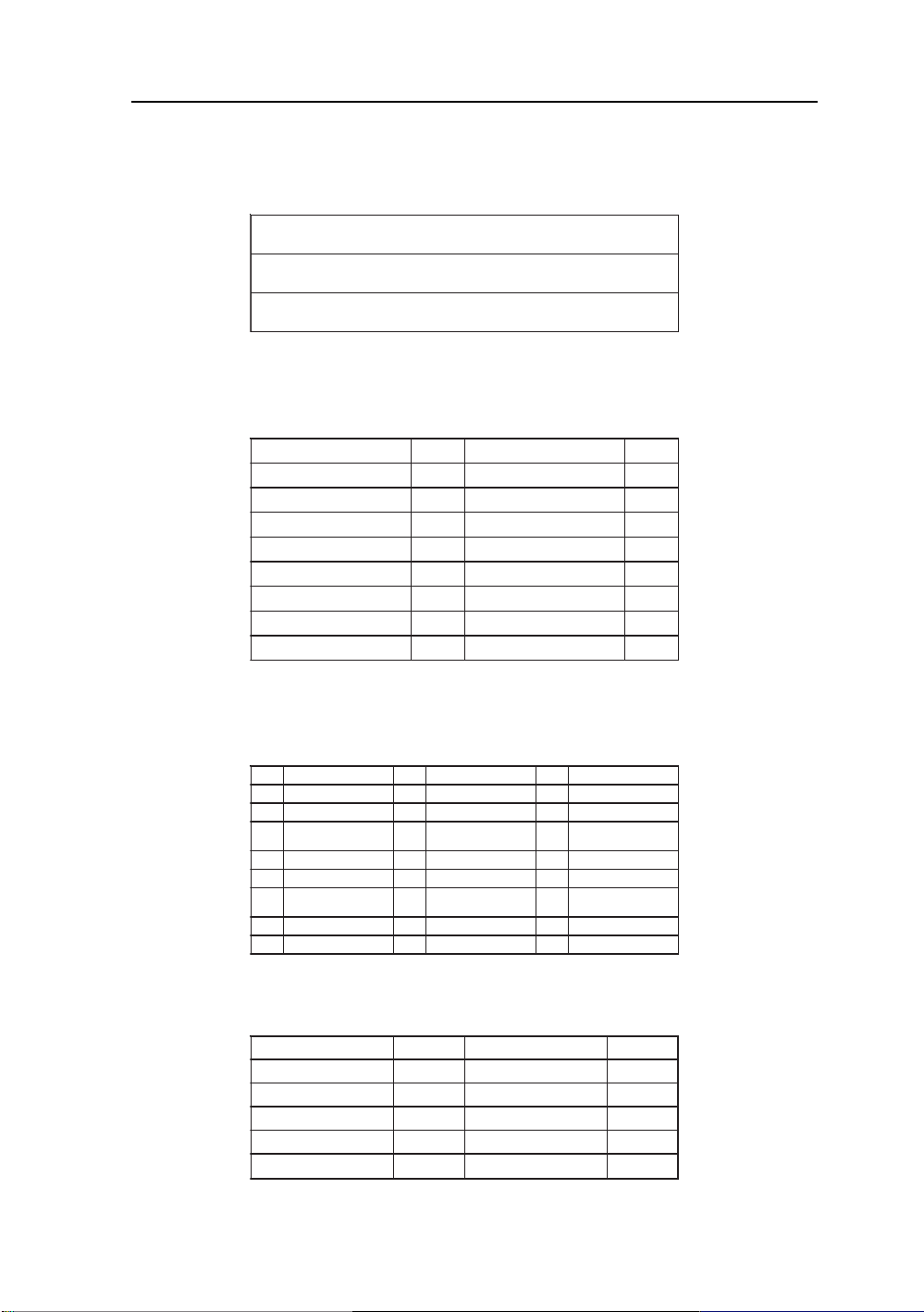
Connectors
DC Input
Connector Jack Power Input
The SCD-014-1-A (SHIUA CHYUAN) or equivalent.
noitpircseDniP
CDV51+1
DNG2
Video Input
15 pin D-subminiature connector.
The vedor P/N is DHSB-15 FRF7(LEOCO) or equivalent.
noitpircseDniPnoitpircseDniP
oediVdeR1CN9
oediVneerG2noCAGV01
oediVeulB3CN11
CN4)2/1CDD(ADS21
dnuorGcigoL5cnys-H31
VdeR6cnys-V41
dnuorGoedi
dnuorGoediVneerG7)B2CDD(LCS51
dnuorGoediVeulB8
AMVX1908 35
24 pin DVI-D connector.
DDWG or equivalent connector.
niPtnemngissAlangiSniPtnemngissAlangiSniPtnemngissAlangiS
1-2ataD.S.D.M.T9-1ataD.S.D.M.T71-0ataD.S.D.M.T
2+2ataD.S
34/2ataD.S.D.M.T
4-4
5+4ataD.S.D.M.T31+3ataD.S.D.M.T22+5ataD.S.D.M.T
6kcolCCDD41rewoPV5+22kco
7ataDCDD51)V5+rof(dnuorG32+kcolC.S.D.M.T
8tcennoCoN61tceteDgulPtoH42-kcolC.S.D.M.T
.D.M.T01+1ataD.S.D.M.T81+0ataD.S.D.M.T
dleihS
Serial Port
9Pin D-subminiature connector.
DCD1RSD6
DXR2STR7
DXT3STC8
RTD4CNIR9
cigoL
dnuorG
113/1ataD.S.D.M.T
ataD.S.D.M.T21-3ataD.S.D.M.T02-5ataD.S.D.M.T
noitpircseDniPnoitpircseDniP
dleihS
5
915/0ataD.S.D.M.T
dleihS
lC.S.D.M.T
dleihS
Page 37

36 User’s Guide
Page 38

 Loading...