

Page 1

Users Manual
Mode d’emploi•
Bedienungshandbuch•
Manuale d’Uso•
Manual de uso•
Användarhandbok•
TMD-10
Dual Temperature
Meter
Page 2

TMD-10
Dual Temperature Meter
Users Manual
TMD10_Rev001
© 2008 Amprobe Test Tools.
All rights reserved.
1
English
Page 3

Limited Warranty and Limitation of Liability
Your Amprobe produc t will be free from de fects in material and workmanship for 1
year from th e date of purchase. T his warranty doe s not cover fuses , disposable bat teries
or damage from accid ent, neglect , misuse, altera tion, contamination, or abnormal
conditio ns of operation or ha ndling. Amprobe’s warrant y obligation is limited, at
Amprob e’s option, to refun d of the purchase price, free of charge repair, or repla cement
of a defec tive product . Re sellers are not au thorized to exten d any other warrant y on
Amprob e’s behalf. To obtain ser vice during the war ranty period, return the p roduct with
proof of pu rchase to an authorized Amprobe Test Tools Service Center or to an Amprobe
dealer or d istributor. See Rep air Section for details. This warra nty is your only rem edy . All
other war ranties - whether e xpress, implied or statutory - i ncluding implied warrantie s of
fitness f or a particular purpose or m erchantabilit y, are hereby excluded. Neither Amprobe
nor its pa rent company or affiliates sh all be liable for any sp ecial, indirect, incide ntal or
conseq uential damages o r losses, arisi ng from any cause or th eory. Since some s tates or
countrie s do not allow the exclu sion or limitation of an implied warrant y or of incidental
or conse quential damage s, this limitation of liabilit y may not apply to you.
Repair
All test to ols returned for warranty or non-warranty repair or for calibra tion should be
accompa nied by the following: your na me, company’s nam e, address, tel ephone number,
and proof o f purchase. Additionally, please include a brief d escription of the problem o r
the ser vice requested and include the tes t leads with the met er. Non-war ranty repair or
replace ment charges sho uld be remitted in t he form of a check, a mo ney order, credit card
with expi ration date, or a purc hase order made payable to Am probe® Test Tools.
In-Warranty Repairs and Replacement – All Countries
Please re ad the warranty st atement and chec k your battery b efore requesting repair.
During the warrant y period any defec tive test tool can be return ed to your Amprobe ®
Test Tools distributor for an excha nge for the same or like produc t. Please check the
“Where to Buy” section on w ww.amprobe.com for a lis t of distributor s near you.
Additionally, in the United Stat es and Canada In- Warranty repair an d replacement units
can also b e sent to a Amprobe® Test Tools Ser vice Center (see below fo r address).
Non-Warranty Repairs and Replacement – US and Canada
Non-warranty repairs in the Unite d States and Canada should be sent to a Amp robe® Test
Tools Service Center. Call Amprobe® Test Tool s or inquire at your poi nt of purchase for
current repair and replacem ent rates.
In USA In Canada
Amprob e Test Tools Amprob e Test Tools
Everett, WA 98203 Missis sauga , ON L4Z 1X9
Tel: 877-993-5853 Tel: 905 -890-7600
Fax: 425 -446- 6390 Fax: 9 05-890 -6866
Non-Warranty Repairs and Replacement – Europe
European n on-warranty units can b e replaced by your Amprobe® Test Tools dis tributor
for a nominal charge. P lease check the “W here to Buy” sec tion on www.amp robe.com for
a list of dis tributors near you.
European Correspondence Address*
Amprob e® Test Tools Europe
Beha-Amprobe GmbH
In den Engematten 14
79286 Glotter tal, Ge rmany
Tel.: +49 (0 ) 7684 8 009 – 0
*(Cor respondence o nly – no repair or repla cement available f rom this address . European
custom ers please contact your d istributor.)
2
Page 4

K/J
REL
+
ºC / ºF
HOLD
T1 T2
T1-T2
MAX
MIN
T2 W T1
24VC
- + MAX - +
J
T1 REL HOLD F C
C
F
N MAX MIN T1- T2
K
J
K
T2
J
1
2
3
4
5
7
9
8
6
W
▲
▼
APO
OFS
SET
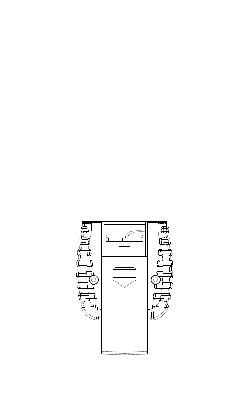
➊ T1 and T2 thermocouple inputs
➋
➌
➍
➎ Power ON /OFF
LCD
°C / °F temperature scales
Data HOLD
APO, turns off Auto Power Off
3
➏ T1, T2, T1-T2
RELative function
➐
OFS, Offset Thermocouple
function
K / J thermocouple types
➑
MAX MIN
➒
SET command to save Thermal
Offset adjustment
Page 5

Dual Temperature Meter
TMD-10
CONTENTS
Symbols ................................................................................................................. 5
Unpacking and Inspection ................................................................................... 5
Introduction ..........................................................................................................5
Operation ............................................................................................................5
°C / °F ...............................................................................................................6
MAX, MIN and AVG ........................................................................................6
K / J ..................................................................................................................6
HOLD ..............................................................................................................6
REL ...................................................................................................................6
T1 T2 / T1-T2 .................................................................................................... 7
Auto Power Off (APO) ....................................................................................7
Thermocouple Error Correction (OFS, Offset) ............................................... 7
Specifications ........................................................................................................8
Maintenance and Repair ....................................................................................9
Battery Replacement ...........................................................................................9
4
Page 6

SYMBOLS
Refer to the manual
Conforms to relevant
Australian standards.
Warning and Precautions
The bead thermocouples supplied with the meter are not intended for •
contact with liquids or electrical circuits.
Do not mix thermocouple types.•
Match the polarity of the adapter to the polarity of the thermocouple •
inputs.
UNPACKING AND INSPECTION
Your shipping carton should include:
1 TMD-10 temperature meter
2 K-type thermocouples
1 9 volt battery
1 Manual
If any of the items are damaged or missing, return the complete package to
the place of purchase for an exchange.
INTRODUCTION
The TMD-10 is a dual input temperature measurement meter using Type K or
Type J thermocouples.
OPERATION
Press the 1. button to turn power on or off
Set the Function Switch to °C or °F. 2.
Select thermocouple type (K / J) and connect the thermocouple(s) to the 3.
T1 or T2 input.
Do not mix thermocouple types.
Match the polarity of the adapter to the polarity of the thermocouple
input.
Expose the thermocouple(s) to the temperature(s) to be measured. 4.
Read the LCD display. 5.
Complies with EU
directives
Do not dispose of this
product as unsorted
municipal waste.
5
Page 7

°C / °F
Press the
scale.
This setting can not be changed when in the HOLD mode. The TMD-10 will
auto save the temperature scale setting during shutdown.
MAX, MIN and AVG
Press the
and average of all readings after the function is enabled. Pressing the
button steps the top reading through the MAX, MIN, and AVG values. Press
the
The MAX, MIN or AVG reading is shown on the top display and the actual
reading is shown on the bottom display for T1.
To use MAX, MIN, and AVG for T2, disable MAX, MIN, and AVG and press and
hold
Press
If the TMD-10 turns off because of Auto Power Off, the recorded values will
be saved for use when the meter is re-energized.
K / J
Press
display.
Press and hold
bottom display.
Press
Press and hold
bottom display.
This setting cannot be changed if in HOLD, MAX/MIN, T1-T2 or REL
modes.
The TMD-10 will auto save the thermocouple type setting during shutdown.
HOLD
Press the
return to normal operation. When the
keys are disabled except for power key.
REL
Relative mode allows the user to offset the subsequent meter measurements
with the top display reading as the reference value.
Press the
couple. The top display will reset to 0.0 (reference value) and subsequently
readings display the difference between the reference value and the actual
reading. The actual reading is shown on the bottom display. Press the
button to disable the Relative function.
key to change from Celsius (°C) to Fahrenheit (°F) temperature
button to start the recording of the maximum, minimum,
button for > 1 second to disable the function.
key > 1 sec to swap T2 to the top display and T1 to bottom display.
button again to activate the function.
key to switch T1 from type K to type J thermocouple for the top
key > 1 sec to swap T2 to the top display and T1 to
key to switch T2 from type K to type J.
key > 1 sec to swap T1 to the top display and T2 to
key to freeze the LCD displays. Press the HOLD key again to
button to enable the Relative function for the T1 thermo-
function is enabled, all function
6
Page 8

To use the Relative mode for T2, disable and press and hold key
> 1 second to swap T2 to the top display and T1 to bottom display.
T1 T2 / T1-T2
T1 T2 displays the 2 inputs independently. Press and hold
second to swap display location of the display location of T1 and T2.
(T1-T2)
button to display T1 minus T2 temperature value. The top display
Press
shows the T1-T2 temperature. The lower display shows the top display
selected in the T1 T2 mode. Press
Auto Power Off (APO)
The TMD-10 powers down automatically after approximately 15 minutes of
inactivity to save battery life. Press the button to turn the TMD-10 ON. You
can disable Auto Power Off by pressing the
TMD-10 is ON.
The power cannot be turned OFF in the OFFSET SETUP mode.
Thermocouple Error Correction (OFS, Offset)
User can add an offset to compensate for the error of specific thermocouple
probes.
Press and hold the 1.
mode.
Immerse the thermocouple(s) in thermos bath with crushed ice and fresh 2.
water (0.0 °C / 32.0 °F).
Press the 3.
Offset value. The allowable adjustment range is ± 5 °C / ± 9 °F in 0.1°C/ °F
increments.
(SET) button to save and leave setup mode. The “Offset” icon
Press 4.
will remain on the LCD.
Press and hold 5.
T1 to bottom display. Press
Repeat steps 1, 2, 3 and 4 for T2. 6.
To remove the Offset, Repeat steps 1, 2, 3 and 4 setting the offset (lower 7.
display) to 0.0. When both thermocouple offset are zeroed out, the
“Offset” icon will be turned off.
(OFS) button > 1 second to enter the Offset Setup
button to increase or power button to decrease the
button > 1 second to swap T2 to the top display and
button again to disable this function
button > 1 second after the
button to switch T2 from type K to type J.
button > 1
7
Page 9

SPECIFICATIONS
General
Display: Dual 5-digit LCD displays
Overrange indication:
“OL” stands for positive temperature
“-OL” stands for negative temperature.
Low battery: the “"sign will appear while battery is low.
Power Supply: 9V NEDA 1604, IEC 6F22, JIS 006P battery.
Battery life: approx. 200 hours.
Auto power off: approx. 15 minutes.
Environment: Indoor operation, - Altitude: Up to 2000 m.
Temperature / Humidity:
Operating: 0°C to 50°C (32°F to 122°F); < 80% RH
Storage: 0°C to 50°C (32°F to 122°F); < 80% RH
Dimensions: 130 x 56 x 38 mm (5.1 x 2.2 x 1.5 in.)
Weight: 170g( 0.37 lb.) battery included
-EMC: EN61326-1 This product complies with requirements of the
following European Community Directives: 89/336/EEC (Electromagnetic
Compatibility) and 73/23/EEC (Low Voltage) as amended by 93/68/EEC (CE
Marking). However, electrical noise or intense electromagnetic fields in the
vicinity of the equipment may disturb the measurement circuit. Measuring
instruments will also respond to unwanted signals that may be present within
the measurement circuit. Users should exercise care and take appropriate
precautions to avoid misleading results when making measurements in the
presence of electronic interference.
Electrical (23 °C ± 5°C, < 80 % RH)
Temperature scale: °C or ° F
Thermocouple type:
K-type: -200°C to 1370 °C (-328 °F to 2498 °F)
J-type: -200°C to 1050 °C (-328°F to 1922 °F)
Resolution: 0.1
Accuracy: ± (0.05 % rdg + 0.7 °C), ± (0.05 % rdg + 1.4 °F)
Input protection: 24V DC or AC.
8
Page 10
OPEN
Temperature Coefficient:
± (0.01 % rdg + 0.03 °C per °C); ± (0.01% rdg + 0.06 °F per °F) outside the
specified + 18 °C to + 28 °C (+ 64°F to + 82°F) range.
Calibration: Yearly
MAINTENANCE AND REPAIR
If there appears to be a malfunction during the operation of the meter, the
following steps should be performed in order to isolate the cause of the
problem.
1. Check the battery. Replace the battery immediately when the symbol “”
appears on the LCD.
2. Review the operating instructions for possible mistakes in operating
procedure.
Except for the replacement of the battery, repair of the meter should be
performed only by a Factory Authorized Service Center or by other qualified
instrument service personnel. The front panel and case can be cleaned with
a mild solution of detergent and water. Apply sparingly with a soft cloth and
allow to dry completely before using. Do not use aromatic hydrocarbons or
chlorinated solvents for cleaning.
BATTERY REPLACEMENT
1. Turn off the meter and slide out the battery cover. Replace the battery with
a NEDA type 1604 or equivalent 9V alkaline battery. Replace the cover.
2. Remove battery when the TMD-10 is not used for extended period.
Battery Replacement
9
Page 11

10
Page 12

TMD-10
Appareil de mesure à
double température
Mode d’emploi
TMD10_Rev001
© 2008 Amprobe Test Tools.
Tous droits réservés.
11
Français
Page 13

Limites de garantie et de responsabilité
Amprob e garantit l’absenc e de vices de matéria ux et de fabricatio n de ce produit pend ant une
périod e d’un an prenant eff et à la date d’achat. Ce tte garantie ne s’app lique pas aux fusib les,
aux piles j etables ni à tout pr oduit mal utilisé, m odifié, contamin é, négligé ou endo mmagé par
acciden t ou soumis à des condi tions anormale s d’utilisation et de m anipulation. L’obligati on
de garanti e d’A mprobe est limit ée, au choix d’Amprob e, au rembourse ment du prix d’achat
ou à la répara tion/remp lacement gratuit d ’un produit défec tueux. Les dis tributeurs agr éés
par Ampro be ne sont pas auto risés à appliquer u ne garantie plus ét endue au nom d’Amprob e.
Pour bén éficier de la garantie , renvoyez le produi t accompagné d’un ju stificatif d’achat a uprès
d’un centr e de services agr éé par Amprobe Test Tool s ou d’un distribut eur ou d’un revendeu r
Amprob e. Voir la section Rép aration pour tous l es détails. La pr ésente garantie e st le seul et
exclusif r ecours toutes au tres garanties, e xplicites, imp licites ou statut aires, notamm ent le
cas éché ant les garanties d e qualité marchand e ou d’adaptation a un ob jectif partic ulier sont
exclues p ar les présente s. Amprobe, la so ciété mère ou ses filia les ne peuvent en au cun cas
être tenu es responsabl es des dommage s particuliers , indirects, a ccidentels ou con sécutifs,
ni d’aucuns d égâts ou perte s de données, su r une base contrac tuelle, extra -contractue lle ou
autre. Et ant donné que cer taines juridic tions n’admetten t pas les limitation s d’une condition
de garanti e implicite, ou l’exclu sion ou la limitatio n de dégâts accid entels ou consécu tifs, il se
peut que l es limitations et /ou les exclu sions de cette gar antie ne s’appliquen t pas à votre cas.
Réparation
Tous les outil s de test renvoyés p our un étalonnag e ou une réparation co uverte ou non par
la garantie d oivent être accom pagnés des élém ents suivants : no m, raison sociale , adresse,
numéro de t éléphone et jus tificatif d’achat. A joutez égalemen t une brève descri ption
du problè me ou du service de mandé et incluez le s cordons de mesu re avec l’appareil. Le s
frais de re mplacement ou de ré paration hors gar antie doivent être a cquittés par chè que,
mandat , carte de crédit av ec date d’expiratio n, ou par bon de comma nde payable à l’ordre d e
Amprob e® Test Tools.
Remplacements et réparations sous garantie – Tous pays
Veuillez lire la d éclaration de gara ntie et vérifier la pil e avant de demander u ne réparation.
Pendant l a période de garant ie, tout outil de tes t défectueux p eut être renvoyé aup rès de
votre dis tributeur Ampro be® Test Tools pour être é changé contre un pr oduit identique o u
similaire . Consultez la sec tion « Where to Buy » sur l e site www.ampr obe.com pour obte nir la
liste de s distributeur s dans votre région. A u Canada et aux Etat s-Unis, les a ppareils devant êt re
remplac és ou réparés sous g arantie peuvent é galement être env oyés dans un centre d e services
Amprob e® Test Tools (voir page su ivante pour les adr esses).
Remplacements et réparations hors garantie – Canada et Etats-Unis
Les appa reils à réparer hor s garantie au Canada e t aux Etats-Un is doivent être envo yés dans
un centre d e services Amp robe® Test Tools. App elez Amprobe® Tes t Too ls ou renseignezvous aupr ès de votre lieu d’acha t pour connaître le s tarifs en vigueu r de remplacemen t ou de
réparation.
Aux Etat s-Unis Au Canada
Ampro be Te st Tools Amprob e Tes t Too ls
Everet t, WA 98203 Mis sissauga, ON L4Z 1X9
Tél : 877-993 -5853 Tél : 905- 890-7600
Fax : 425-44 6-6390 Fax : 905 -890-6 866
Remplacements et réparations hors garantie – Europe
Les appa reils européens n on couverts pa r la garantie peuven t être remplacés pa r votre
distrib uteur Amprobe ® Tes t To ols pour une somme n ominale. Consul tez la section « Whe re to
Buy » sur le si te www.amprob e.com pour obten ir la liste des distr ibuteurs dans vo tre région.
Adres se postale européenne*
Amprobe
Beha- Amprobe GmbH
In den Engematten 14
79286 Gl ottertal, Allemagne
Tél. : +49 ( 0) 7684 80 09 - 0
*(Ré servée à la corre spondance – Aucun e réparation ou remp lacement n’est po ssible à cette
adress e. Nos clients euro péens doivent co ntacter leur di stributeur.)
®
Test Tools Europ e
12
Page 14

K/J
REL
+
ºC / ºF
HOLD
T1 T2
T1-T2
MAX
MIN
T2 W T1
24VC
- + MAX - +
J
T1 REL HOLD F C
C
F
N MAX MIN T1- T2
K
J
K
T2
J
1
2
3
4
5
7
9
8
6
W
▲
▼
APO
OFS
SET
➊ Entrées de thermocouples
➋
➌
➍
➎
T1 et T2
Ecran LCD
Echelles de température °C / °F
Maintien des données HOLD,
APO met l’appareil hors tension
Bouton marche/arrêt
T1 T2 / T1-T2
➏
Fonction RELatif OFS, fonction
➐
de décalage de thermocouple
Types de thermocouples K / J
➑
MAX MIN
➒
Commande SET pour
enregistrer le réglage du
décalage thermique
13
Page 15

Appareil de mesure à double température
TMD-10
Symboles ............................................................................................................. 15
Déballage et inspection ..................................................................................... 15
Introduction ........................................................................................................15
Fonctionnement ................................................................................................ 15
°C / °F .............................................................................................................16
MAX, MIN et AVG .........................................................................................16
K / J ................................................................................................................16
Maintien d’affichage ................................................................................... 16
REL .................................................................................................................16
T1 T2 / T1-T2 .................................................................................................. 17
Arrêt automatique (APO) .............................................................................17
Correction des erreurs de thermocouple (OFS, Offset) ..............................17
Caractéristiques générales .................................................................................18
Entretien et reparation .....................................................................................19
Changement des piles .......................................................................................19
14
Page 16

SYMBOLES
Se reporter au
mode d’emploi.
Conforme aux normes
australiennes.
Conforme aux
directives de l’UE.
Ne pas mettre ce
produit au rebut parmi
les déchets ménagers.
Mises en garde et précautions
Les thermocouples à perle fournis avec l’appareil ne sont pas conçus pour •
entrer en contact avec l’eau ou les circuits électriques.
Ne pas mélanger les types de thermocouples.•
Aligner la polarité de l’adaptateur sur celle des entrées de thermocouple. •
DÉBALLAGE ET INSPECTION
Le carton d’emballage doit inclure les éléments suivants :
1 Appareil de mesure de température TMD-10
2 Thermocouples de type K
1 Pile de 9 volts
1 Manuel
Si l’un de ces éléments est endommagé ou manquant, renvoyez le con t enu
complet de l’emballage au lieu d’achat pour l’échanger.
INTRODUCTION
Le TMD-10 est un appareil de température à deux entrées utilisant des
thermocouples de type K ou de type J.
FONCTIONNEMENT
Appuyez sur le bouton 1. pour mettre l’appareil sous ou hors tension.
Réglez le sélecteur de fonction sur °C ou °F. 2.
Sélectionnez le type de thermocouple (K / J) et raccordez le(s) 3.
thermocouple(s) à l’entrée T1 ou T2.
Ne pas mélanger les types de thermocouples.
Aligner la polarité de l’adaptateur sur celle des entrées de thermocouple.
Exposez le(s) thermocouple(s) aux températures à mesurer. 4.
Lisez l’affichage LCD. 5.
15
Page 17

°C / °F
Appuyez sur la touche
température Celsius (°C) et Fahrenheit (°F).
Ce réglage ne peut pas être modifié en mode de maintien HOLD. Pendant
la mise hors tension, le TMD-10 conserve automatiquement l’échelle de
température définie.
MAX, MIN et AVG
Appuyez sur le bouton
maximum, minimum et moyenne de toutes les mesures relevées après
l’activation de la fonction. La pression du bouton fait défiler les mesures
du volet supérieur sur les valeurs MAX, MIN et AVG. Appuyez sur le bouton
pendant > 1 seconde pour désactiver la fonction.
La mesure MAX, MIN ou AVG apparaît sur la fenêtre supérieure et la valeur
réelle sur la fenêtre inférieure dans le cas de T1.
Pour utiliser MAX, MIN et AVG pour T2, désactivez MAX, MIN et AVG et
maintenez la touche
fenêtre supérieure et T1 vers la fenêtre inférieure.
Appuyez de nouveau sur le bouton
Si le TMD-10 s’éteint en raison d’un arrêt automatique (APO), les valeurs
enregistrées sont conservées lorsque l’appareil est remis sous tension.
K / J
Appuyez sur la touche
K et de type J dans la fenêtre supérieure.
Maintenez la touche
fenêtre supérieure et T1 vers la fenêtre inférieure.
Appuyez sur la touche
K et de type J.
Maintenez la touche
fenêtre supérieure et T2 vers la fenêtre inférieure.
Ce paramètre ne peut pas être modifié si les modes HOLD, MAX/MIN,
T1-T2 ou REL sont actifs.
Pendant la mise hors tension, le TMD-10 conserve automatiquement le type
de thermocouple défini.
Maintien d’affichage
Appuyez sur la touche
sur la touche HOLD pour revenir au mode de fonctionnement normal.
Lorsque la fonction
désactivées à l’exception de la touche d’alimentation .
REL
Le mode relatif permet de régler le décalage des mesures consécutives en
utilisant la valeur de référence affichée sur la fenêtre supérieure.
pour basculer entre l’échelle de
pour lancer l’enregistrement des valeurs
enfoncée pendant > 1 s pour basculer T2 vers la
pour activer la fonction.
pour basculer T1 entre un thermocouple de type
enfoncée pendant > 1 s pour basculer T2 vers la
pour basculer T2 entre un thermocouple de type
enfoncée pendant > 1 s pour basculer T1 vers la
pour geler l’affichage LCD. Appuyez de nouveau
st activée, toutes les touches de fonction sont
16
Page 18

Appuyez sur le bouton pour activer la fonction de mesure relative
pour le thermocouple T1. La fenêtre supérieure est remise sur 0,0 (valeur de
référence) et les mesures consécutives affichent la différence entre la valeur de
référence et la valeur réelle. La valeur réelle apparaît sur la fenêtre inférieure.
Appuyez de nouveau sur le bouton
Pour utiliser le mode Relatif pour T2, désactivez
touche
supérieure et T1 vers la fenêtre inférieure.
T1 T2 / T1-T2
T1 T2 affiche les 2 entrées en mode indépendant. Maintenez le bouton
T1 et de T2.
(T1-T2)
Appuyez sur le bouton
T2. La fenêtre supérieure affiche la température T1-T2. La fenêtre inférieure
affiche la fenêtre supérieure sélectionnée dans le mode T1 T2. Appuyez de
nouveau sur le bouton
Arrêt automatique (APO)
Pour préserver la durée des piles, le TMD-10 s’arrête automatiquement après
environ 15 minutes d’inactivité. Appuyez sur le bouton pour mettre le
TMD-10 sous tension. Vous pouvez désactiver l’arrêt automatique (APO) en
appuyant sur le bouton
du TMD-10.
L’appareil ne peut pas être mis hors tension en mode de configuration du
décalage (OFFSET SETUP).
Correction des erreurs de thermocouple (OFS, Offset)
L’utilisateur peut ajouter un décalage pour compenser l’erreur des sondes de
thermocouple spécifiques.
enfoncée pendant > 1 seconde pour basculer T2 vers la fenêtre
enfoncé pendant > 1 seconde pour basculer la fenêtre d’affichage de
pour afficher T1 moins la valeur de température
pour désactiver cette fonction.
pendant > 1 seconde après la mise sous tension
Maintenez le bouton 1.
en mode OFFSET SETUP.
Plongez le(s) thermocouple(s) dans un bain isotherme de glace pilée et 2.
d’eau douce (0,0 °C / 32,0 °F).
Appuyez sur le bouton 3.
d’alimentation + pour diminuer le décalage. La gamme de réglage
autorisée est ± 5 °C / ± 9 °F par incréments de 0,1 °C/°F.
Appuyez sur le bouton 4.
configuration. L’icône « Offset » reste affichée sur l’écran LCD.
Maintenez le bouton 5.
T2 vers la fenêtre supérieure et T1 vers la fenêtre inférieure. Appuyez sur
le bouton
type J.
Répétez les étapes 1, 2, 3 et 4 pour T2. 6.
Pour supprimer le décalage, répétez les étapes 1, 2, 3 et 4 pour régler 7.
le décalage (fenêtre inférieure) sur 0,0. Lorsque les deux décalages de
thermocouple sont remis à zéro, l’icône « Offset » s’éteint.
pour basculer T2 entre un thermocouple de type K et de
pour désactiver la fonction Relative.
et maintenez la
(OFS) enfoncé pendant > 1 seconde pour passer
pour augmenter ou sur le bouton
(SET) pour enregistrer et quitter le mode de
enfoncé pendant > 1 seconde pour basculer
17
Page 19

CARACTÉRISTIQUES GÉNÉRALES
Caractéristiques générales
Affichage : Double affichage LCD à 5 chiffres
Indication de dépassement de calibre :
« OL » indique une température positive
« -OL » indique une température négative
Pile faible : le signe « » apparaît quand la pile est faible
Alimentation : Pile 9 V NEDA 1604, CEI 6F22, JIS 006P.
Durée de vie de pile : environ 200 heures
Arrêt automatique : environ 15 minutes
Environnement : Fonction en intérieur, - altitude : jusqu’à 2 000 mètres
Température/Humidité :
Fonctionnement : 0 °C à 50 °C (32 °F à 122 °F) ; < 80 % HR
Entreposage : 0 °C à 50 °C (32 °F à 122 °F) ; < 80 % HR
Dimensions : 130 x 56 x 38 mm (5,1 x 2,2 x 1,5 po)
Poids : 170 g (0,37 lb) pile comprise
-CEM : EN61326-1. Ce produit est conforme aux exigences des
directives suivantes de la Communauté européenne : 89/336/CEE
(Compatibilité électromagnétique) et 73/23/CEE (Basse tension) modifiée
par 93/68/CEE (Marquage CE). Toutefois, le bruit électrique ou les champs
électromagnétiques intenses à proximité de l’équipement sont susceptibles
de perturber le circuit de mesure. Les appareils de mesure réagissent
également aux signaux indésirables parfois présents dans le circuit de mesure.
Les utilisateurs doivent faire preuve de prudence et prendre les mesures
nécessaires pour éviter les erreurs de mesure en présence de parasites
électromagnétiques.
Electricité (23 °C ± 5 °C, < 80 % HR)
Echelle de température : °C ou °F
Type de thermocouple :
Type K : -200 °C à 1370 °C (-328 °F à 2498 °F)
Type J : -200 °C à 1050 °C (-328 °F à 1922 °F)
Résolution : 0,1
Précision : ± (0,05 % de lecture + 0,7 °C), ± (0,05 % de lecture + 1,4 °F)
Protection d’entrée : 24 V c.c. ou c.a.
18
Page 20

Coefficient thermique :
OPEN
± (0,01 % de lecture + 0,03 °C par °C) ; ± (0,01 % de lecture + 0,06 °F par °F)
en dehors de la gamme + 18 °C à + 28 °C (+ 64 °F à + 82 °F) spécifiée
Etalonnage : annuel
ENTRETIEN ET REPARATION
Si une anomalie est suspectée pendant le fonctionnement du multimètre,
procédez comme suit pour isoler la cause du problème.
1. Vérifiez la pile. Remplacez immédiatement les piles à l’apparition du
symbole « » sur l’écran LCD.
2. Consultez les consignes d’utilisation pour vérifier les erreurs possibles lors
de l’utilisation.
A l’exception du changement des piles, la réparation de l’appareil doit être
effectuée en usine dans un centre de service agréé ou par un autre personnel
de réparation qualifié. La face avant et le boîtier peuvent être nettoyés
à l’aide d’une solution légère à base d’eau et de détergent. Appliquez
cette solution avec modération en utilisant un tissu doux et laissez bien
sécher avant l’utilisation. N’utilisez pas de solvants à base de chlore ou
d’hydrocarbures aromatiques pour le nettoyage.
CHANGEMENT DES PILES
1. Mettez l’appareil hors tension et faites glisser le couvercle du
compartiment de pile. Installez une pile alcaline neuve de 9 V NEDA
type 1604 ou équivalente. Replacez le couvercle.
2. Retirez la pile si le TMD-10 n’est pas utilisé pendant une période prolongée.
Changement des piles
19
Page 21

20
Page 22

TMD-10
Dual-Temperaturmessgerät
Bedienungshandbuch
TMD10_Rev001
© 2008 Amprobe Test Tools.
Alle Rechte vorbehalten.
21
Deutsch
Page 23

Beschränkte Gewährleistung und Haf tungsbeschränkung
Es wird gewährleistet, dass die ses Amprobe-Produkt für die Dauer von einem Jahr ab
dem Kaufdatum frei von Material- und Fertigungsdefe kten ist. Diese Gewährleis tung
erstre ckt sich nicht auf Sicherungen, Einwegbat terien oder Schäde n durch Unfälle,
Nachlässigkeit, Missbrauch, Änderu ngen oder abnormale Betriebs bedingungen bzw.
unsachg emäße Handhabung. Die Garantieverpflichtung von Amprobe beschränkt
sich darauf, da ss Amprobe nach eige nem Ermessen den Kau fpreis ersetzt oder aber
das defek te Produkt unentgeltlich repa riert oder austauscht. Die Verkaufsstellen sind
nicht dazu berechtigt , diese Gewährleistung im Namen von Amprobe zu erweite rn. Um
während de r G ewährleistungsperiode Serviceleistung en zu beanspruchen , das Produkt
mit Kaufnac hweis an ein autorisier tes Amprobe Test Tools Service-Cente r o der an einen
Amprobe -Fachhändler/-Di stributor einsenden. Nähere Einzelheiten siehe Abschnitt
„Reparatu r“. Die se Gewährleistung s tellt den einzigen und all einigen Rechtsan spruch auf
Schaden ersatz dar. Alle andere n Gewährleistungen, vertraglich gere gelte oder geset zlich
vorgeschriebene, einschli eßlich der gesetzlichen Gewährleistun g der Marktfähigkeit und
der Eignung für einen bestimmten Zweck, werden abgelehnt. Weder Amprobe noch
dessen M uttergesellschaft oder Tochterges ellschaften übe rnehmen Haftung für spezielle,
indirekte, Neben - oder Folgeschäden oder für Verluste, di e auf beliebig er Ursache
oder Rechtstheo rie beruhen. Weil einige Staaten oder Länder den Ausschluss oder die
Einschränkung einer implizierte n Gewährleistung sowie den Ausschluss vo n Begleit- ode r
Folgeschäden nich t zulassen, ist diese Gewährleis tungsbeschrän kung möglicherweise für
Sie nicht gültig.
Reparatur
Alle Geräte n, die innerhalb oder außerhalb de s Garantiezeitraums zur Reparatur oder
Kalibrierung eingesendet we rden, müssen mit folgenden Informationen und Dokumenten
versehen werden : Name des Kunden, Firm enname, Adresse, Telefonnummer und
Kaufbeleg. Zusät zlich bitte dem Mess gerät eine kurze Beschreibung de s Problems oder der
gewünschten Wartu ng sowie die Messleitungen beilegen. Die G ebühren für Reparatu ren
außerhalb der Garantie o der für den Ersatz von I nstrumenten müs sen per Scheck,
Geldanweisung oder Kreditkarte (Kreditkar tennummer mit Ablaufdatum) b eglichen
werden o der es muss ein Auf trag an Amprobe ® Tes t Too ls formuliert we rden.
Garantiereparaturen und -austausch - alle L änder
Bitte die Garantie erklärung lese n und die Batterie prüfen, b evor Reparaturen angeford ert
werden. Während der Garantieperiode können alle defekten Geräte zum Umtausch gegen
dasselb e oder ein ähnliches Pro dukt an den Amprobe ® Tes t Tool s-Distributor gesendet
werden. Ein Verzeichnis der zustän digen Distributoren ist im Abschnitt „Wh ere to Buy“
(Verkauf sstellen) auf der We bsite www.amprobe.com zu finden. Darüb er hinaus können in
den USA und in Kanada Geräte an ein Amprobe® Test Tools Ser vice-Center (Adress e siehe
nächst e Seite) zur Repara tur oder zum Umtau sch eingesend et werden.
Reparaturen und Ersatz außerhalb des Garantiezeitraums - USA und
Kanada
Für Repara turen außerhalb des Garanti ezeitraums in den Vere inigten Staaten un d in
Kanada we rden die Geräte an ein Amprob e® Te st Tools Service -Center gesendet. Auskunf t
über die derzeit geltenden Reparatur- und Aus tauschgebühren erhalten Sie von Ampro be®
Test Tools ode r der Verkaufsstelle.
In den USA In Kanada
Amprobe Tes t Tools Amprobe Test Tool s
Everet t, WA 98203 Mis sissauga, Ontario L4Z 1X9
Tel: 877-9 93-5853 Tel: 905-8 90-7600
Fax: 425-4 46-6390 Fa x: 905-890- 6866
Reparaturen und Austausch außerhalb des Garantiezeitraums - Europa
Geräte mit ab gelaufener Garantie können durch den zustän digen Amprobe® Test
Tools-Distributor gegen eine Gebühr er setzt werden. Ein Verzeichnis de r zu ständigen
Distrib utoren ist im Abs chnitt „Where to Bu y“ (Verkaufss tellen) auf der Web site www.
amprobe.com zu find en.
Korrespondenzanschrift für Eu ropa*
Amprobe
Beha- Amprobe GmbH
In den Engematten 14
79286 Gl ottertal, Ge rmany
Tel.: + 49 (0) 7684 8 009 - 0
*(Nur Korrespondenz – keine Reparaturen und kein Umtausch unter dieser Anschrif t.
Kunden in Europa wend en sich an den zuständigen Distrib utor.)
®
Test Tools Europ e
22
Page 24

K/J
REL
+
ºC / ºF
HOLD
T1 T2
T1-T2
MAX
MIN
T2 W T1
24VC
- + MAX - +
J
T1 REL HOLD F C
C
F
N MAX MIN T1- T2
K
J
K
T2
J
1
2
3
4
5
7
9
8
6
W
▲
▼
APO
OFS
SET
➊ Thermoelementeingänge T1
und T2
LCD-Anzeige
➋
Temperaturskalen °C / °F
➌
HOLD, Datenhaltemodus APO,
➍
automatische Abschaltung
EIN-/AUSSCHALTER
➎
T1 T2 / T1-T2
➏
RELativ-Funktion OFS, Offset-
➐
Thermoelement-Funktion
Thermoelementtypen K / J
➑
MAX MIN
➒
SET-Befehl zum Speichern der
Wärmeoffseteinstellung
23
Page 25

Dual-Temperaturmessgerät
TMD-10
Symbole ..............................................................................................................25
Auspacken und Überprüfen ..............................................................................25
Einführung ..........................................................................................................25
Bedienung .........................................................................................................25
°C / °F .............................................................................................................26
MAX, MIN, AVG ...........................................................................................26
K / J ................................................................................................................26
HOLD ............................................................................................................26
REL ................................................................................................................26
T1 T2 / T1-T2 .................................................................................................. 27
Automatische Abschaltung (APO) ...............................................................27
Thermoelement-Fehlerkorrektur (OFS, Offset) ...........................................27
Spezifikationen ..................................................................................................28
Wartung und Reparatur ...................................................................................29
Ersetzen der Batterie ........................................................................................29
24
Page 26

SYMBOLE
Im Handbuch nachlesen.
Übereinstimmung
mit den relevanten
australischen Normen.
Übereinstimmung mit
EU-Vorschriften.
Dieses Produkt nicht
im unsortierten
Kommunalabfall
entsorgen.
Warn- und Vorsichtshinweise
Die im Lieferumfang des Messgeräts enthaltenen Thermoelemente sind •
nicht für den Kontakt mit Flüssigkeiten oder elektrischen Stromkreisen
vorgesehen.
Keine Thermoelemente verschiedener Typen gleichzeitig verwenden.•
Die Polarität des Adapters an die Polarität der Thermoelementeingänge •
anpassen.
AUSPACKEN UND ÜBERPRÜFEN
Der Verpackungskarton sollte Folgendes enthalten:
1 Temperaturmessgerät TMD-10
2 Thermoelement Typ K
1 9-Volt-Batterie
1 Handbuch
Wenn einer dieser Artikel beschädigt ist oder fehlt, die gesamte Lieferung
zwecks Ersatz an die Verkaufsstelle zurücksenden.
EINFÜHRUNG
Das TMD-10 ist ein Temperaturmessgerät mit zwei Eingängen für die
Verwendung mit Typ-K- oder Typ-J-Thermoelementen.
BEDIENUNG
Die Taste 1. drücken, um das Gerät ein- bzw. auszuschalten.
Den Funktionsschalter auf °C oder °F schalten. 2.
Den Thermoelementtyp (K / J) auswählen und die Thermoelemente an 3.
T1 bzw. T2 anschließen.
Keine Thermoelemente verschiedener Typen gleichzeitig verwenden.
Die Polarität des Adapters an die Polarität der Thermoelementeingänge
anpassen.
Die Thermoelemente den zu messenden Temperaturen aussetzen. 4.
Die LCD-Anzeige ablesen. 5.
25
Page 27

°C / °F
Die Taste
skala zu schalten.
Diese Einstellung kann nicht verändert werden, wenn der HOLD-Modus
aktiviert ist. Das TMD-10 speichert die Temperaturskala während des
Abschaltvorgangs automatisch.
MAX, MIN, AVG
Die Taste
Mittelwerte aller Messwerte nach Aktivierung der Funktion zu beginnen.
Drücken der Taste
als oberen Wert an. Die Taste
die Funktion zu deaktivieren.
Der MAX-, MIN- bzw. AVG-Wert wird auf der oberen Anzeige angezeigt und
der tatsächliche Messwert wird auf der unteren Anzeige für T1 angezeigt.
Um MAX, MIN und AVG für T2 zu verwenden, MAX, MIN und AVG
deaktivieren und die Taste
sodass T2 auf der oberen und T1 auf der unteren Anzeige angezeigt wird.
Die Taste
Wenn das TMD-10 aufgrund der automatischen Abschaltfunktion ausschaltet,
werden die aufgezeichneten Werte für später gespeichert, wenn das
Messgerät wieder eingeschaltet wird.
K / J
Die Taste
obere Anzeige umzuschalten.
Die Taste
und T1 auf der unteren Anzeige anzuzeigen.
Die Taste
Die Taste
und T2 auf der unteren Anzeige anzuzeigen.
Diese Einstellung kann nicht verändert werden, wenn HOLD, MAX/MIN,
T1-T2 oder REL aktiviert ist.
Das TMD-10 speichert die Thermoelementtypeinstellung während des
Abschaltvorgangs automatisch.
HOLD
Die Taste
HOLD erneut drücken, um zum Normalbetrieb zurückzukehren. Wenn die
Funktion
Ein-Aus-Taste deaktiviert.
REL
Mit dem Relativ-Modus können Bediener nachfolgende Messgerätmessungen
unter Verwendung der oberen Anzeige als Referenzwert versetzen.
Die Taste
drücken, um von Celsius (°C)- auf Fahrenheit (°F)-Temperatur-
drücken, um die Aufzeichnung der Niedrigst-, Höchst- und
zeigt der Reihe nach die Werte MAX, MIN und AVG
erneut drücken, um die Funktion zu aktivieren.
drücken, um T1 von Typ K zu Typ J Thermoelement für die
mehr als eine Sekunde gedrückt halten, um T2 auf der oberen
drücken, um T2 von Typ K zu Typ J umzuschalten.
mehr als eine Sekunde gedrückt halten, um T1 auf der oberen
drücken, um die LCD-Anzeige „festzustellen“. Die Taste
aktiviert ist, sind alle Funktionstasten mit Ausnahme der
drücken, um die Relativ-Funktion für das T1-Thermoelement
mehr als 1 Sekunde gedrückt halten, um
mehr als eine Sekunde gedrückt halten,
26
Page 28

zu aktivieren. Die obere Anzeige wird auf 0,0 (Referenzwert) zurückgesetzt
und nachfolgende Messwerte zeigen die Differenz zwischen dem
Referenzwert und dem tatsächlichen Messwert an. Der tatsächliche Messwert
wird auf der unteren Anzeige angezeigt. Die Taste
Relativ-Funktion zu deaktivieren.
Um den Relativ-Modus für T2 zu verwenden,
mehr als eine Sekunde gedrückt halten, sodass T2 auf der oberen und
T1 auf der unteren Anzeige angezeigt wird.
T1 T2 / T1-T2
T1 T2 zeigt die zwei Eingänge in unabhängiger Weise an. Die Taste
mehr als eine Sekunde gedrückt halten, um die Anzeige (unten/oben) von T1
und T2 auszutauschen.
(T1-T2)
Die Taste
Die obere Anzeige zeigt die T1-T2-Temperatur an. Die untere Anzeige zeigt
die obere Anzeige im T1 T2-Modus an. Die Taste
diese Funktion zu deaktivieren.
Automatische Abschaltung (APO)
Um Batteriestrom zu sparen, schaltet sich das TMD-10 nach ungefähr
15 Minuten Inaktivität automatisch aus. Die Taste drücken, um das TMD-10
einzuschalten. Nachdem das TDM-10 eingeschaltet ist, kann automatische
Abschaltung (APO) durch Gedrückthalten der Taste
1 Sekunde deaktiviert werden.
Im Modus OFFSET SETUP kann das Messgerät nicht ausgeschaltet werden.
Thermoelement-Fehlerkorrektur (OFS, Offset)
Bediener kann ein Offset hinzufügen, um für den Fehler bestimmter
Thermoelementsonden zu kompensieren.
Die Taste 1.
in den Offset-Setup-Modus zu schalten.
Die Thermoelemente in Wärmebad mit zerkleinerten Eiswürfeln und 2.
Frischwasser (0,0 °C / 32,0 °F) eintauchen.
Die Taste 3.
Aus-Taste drücken, um den Offsetwert zu vermindern . Der zulässige
Anpassungsbereich ist ± 5 °C / ± 9 °F in Schritten von 0,1 °C/°F.
Die Taste 4.
beenden. Das Offset-Symbol bleibt auf der LCD angezeigt.
Die Taste 5.
oberen und T1 auf der unteren Anzeige anzuzeigen. Die Taste
drücken, um T2 von Typ K zu Typ J umzuschalten.
Die Schritte 1, 2, 3 und 4 für T2 wiederholen. 6.
Um das Offset zu entfernen, die Schritte 1, 2, 3 und 4 wiederholen 7.
und das Offset (untere Anzeige) auf 0,0 einstellen. Wenn beide
Thermoelementoffsetwerte auf Null gesetzt werden, wird das OffsetSymbol ausgeblendet.
drücken, um den Temperaturwert T1 minus T2 anzuzeigen.
(OFS) drücken und mehr als 1 Sekunde gedrückt halten, um
drücken um den Offsetwert zu erhöhen, oder die Ein-
(SET) drücken, um zu speichern und Setup-Modus zu
mehr als eine Sekunde gedrückt halten, um T2 auf der
drücken, um die
deaktivieren und die Taste
erneut drücken, um
für mehr als
27
Page 29

SPEZIFIKATIONEN
Allgemein
Anzeige: Doppelte fünfstellige LCD-Anzeige
Überschreitungsanzeige:
„OL” steht für positive Temperatur
„-OL” steht für negative Temperatur
Schwache Batterie: das Symbol „“ erscheint, wenn die Batterie schwach ist
Stromversorgung: Batterie 9-V-NEDA 1604, IEC 6F22, JIS 006P
Batterielebensdauer: ungefähr 200 Stunden
Automatische Ausschaltung: ungefähr 15 Minuten
Umgebung: Innenverwendung, - Höhenlage: bis 2000 m
Temperatur / Feuchtigkeit:
Betrieb: 0 °C bis 50 °C (32 °F bis 122 °F); < 80 % RH
Lagerung: 0 °C bis 50 °C (32 °F bis 122 °F); < 80 % RH
Abmessungen: 130 x 56 x 38 mm
Gewicht: 170 g, einschließlich Batterie
-EMV: EN61326-1. Dieses Produkt erfüllt die Anforderungen
der folgenden EU-Richtlinien: 89/336/EEC (Elektromagnetische
Verträglichkeit) und 73/23/EEC (Niederspannung) mit dem Zusatz
93/68/EEC (CE-Kennzeichnung). Elektrisches Rauschen oder intensive
elektromagnetische Felder in der Nähe des Geräts können jedoch den
Messschaltkreis stören. Messgeräte reagieren auch auf unerwünschte
Impulse/Signale, die unter Umständen im Messschaltkreis vorkommen.
Die Benutzer müssen die nötige Sorgfalt walten lassen und geeignete
Vorkehrungen treffen, um irreführende Ergebnisse bei Messungen
elektrischer Störeinflüsse zu vermeiden.
Elektrisch (23 °C ± 5 °C, < 80 % RH)
Temperaturskala: °C oder °F
Thermoelementtyp:
Typ K: -200 °C bis 1370 °C (-328 °F bis 2498 °F)
J-Typ: -200 °C bis 1050 °C (-328 °F bis 1922 °F)
Auflösung: 0,1
Genauigkeit: ± (0,05 % Messwert + 0,7 °C), ± (0,05 % Messwert + 1,4 °F)
Eingangsschutz: 24 V DC oder AC
28
Page 30

OPEN
Temperaturkoeffizient:
± (0,01 % Messwert + 0,03 °C pro °C); ± (0,01 % Messwert + 0,06 °F pro °F)
außerhalb des spezifizierten Bereichs von + 18 °C bis + 28 °C (+ 64 °F bis + 82 °F)
Kalibrierung: jährlich
WARTUNG UND REPARATUR
Wenn ein Fehlverhalten während des Betriebs des Messgeräts vermutet wird,
sollten die folgenden Schritte durchgeführt werden, um die Ursache des
Problems genau zu bestimmen.
1. Die Batterien prüfen. Die Batterie sofort ersetzen, wenn das Symbol „“
auf der LCD-Anzeige erscheint.
2. Die Bedienungsanleitungen studieren, um mögliche Fehler bei der
Bedienung zu erkennen.
Außer dem Ersetzen der Batterie sollten Reparaturen am Messgerät
ausschließlich durch werkseitig autorisiertes Servicepersonal oder anderes
Fachpersonal durchgeführt werden. Die Vorderseite und das Gehäuse
können mit einer milden Lösung von Reinigungsmittel und Wasser gereinigt
werden. Die Lösung spärlich mit einem weichen Tuch anwenden und
das Gerät vor Gebrauch vollständig trocknen lassen. Keine aromatischen
Kohlenwasserstoffe oder Chlorlösungsmittel zur Reinigung verwenden.
ERSETZEN DER BATTERIE
1. Das Messgerät ausschalten und die Batterieabdeckung aufschieben. Die
Batterie durch eine NEDA Typ 1604 oder eine gleichwertige 9-V-Alkalibatterie
ersetzen. Die Abdeckung wieder anbringen.
2. Die Batterie entfernen, wenn das TMD-10 längere Zeit nicht verwendet
wird.
Ersetzen der Batterie
29
Page 31

30
Page 32

TMD-10
Termometro a
doppio ingresso
Manuale d’Uso
TMD10_Rev001
© 2008 Amprobe Test Tools.
Tutti i diritti riservati.
Italiano
31
Page 33

Garanzia limitata e limitazione di responsabilità
Questo prodotto Amprobe sarà esente da difet ti di materiale e fabbricazione
per un anno a decorrere dalla data di acquisto. S ono esclusi da questa garanzia
i fusibili, le pile monouso e i danni causati da incidenti, negligenza, uso
improprio, alterazione, contaminazione o condizioni anomale di funzionamento
o maneggiamento. L’obbligo di garanzia è limitato, a scelta della Amprob e, al
rimbor so del prezzo d’acquisto, alla riparazione gratuita o alla sostituzione di
un prodotto difettoso. I rivenditori non sono autorizzati a offrire nessun’altra
garanzia a nome della Amprobe. Per richiedere un intervento durante il periodo
di garanzia restituire il prodotto, allegando la ricevuta di acquisto, a un centro di
assistenza autorizzato Amprobe Test Tools oppure a un rivenditore o distributore
Amprobe locale. Per ulteriori informazioni vedere la sezione Riparazioni. Questa
garanzia è il solo ricor so a disposizione dell’acquirente e sostituisce qualsiasi altra
garanzia, espressa, implicita o prevista dalla legge, compresa qualsiasi garanzia
implicita di commerciabilità o di ido neità per scopi particolari. Né la Amprobe né
la sua società madre o sue af filiate saranno responsabili di danni o perdite speciali,
indiret ti o accidentali, derivanti da qualsiasi causa o teoria. Poiché alcuni s tati o
Paesi non permettono l’esclusione o la limitazione di una garanzia implicita o di
danni accidentali o indiret ti, questa limitazione di responsabilità potrebbe non
riguardare l’acquirente.
Riparazioni
A tutti gli strumenti di misura restituiti per interventi in garanzia o non coperti
dalla garanzia, oppure per la taratura, devono essere allegate le seguenti
informazioni: il proprio nome e quello dell’azienda, indirizzo, numero telefonico
e ricevuta di acquisto. Allegare anche una breve descrizione del problema o
dell’intervento richiesto e i cavi di misura. Gli importi dovuti per sostituzioni
o riparazioni non coperte dalla garanzia vanno versati tramite assegno, vaglia
bancario, carta di credito con data di scadenza, oppure ordine di acquisto
all’ordine di Amprobe® Test Tools.
Sostituzioni e riparazioni in garanzia – Tutti i Paesi
Si prega di leggere la garanzia e di controllare le pile prima di richiedere una
riparazione. Durante il periodo di garanzia, si può restituire uno strume nto
difettoso al rivenditore Amprobe® Test Tools per ricevere un prodotto identico
o analogo. La sezione “Where to Buy” del sito www.amprobe.com contiene
un elenco dei distributori più vicini. Negli St ati Uniti e nel Canada gli strumenti
da sostituire o riparare in garanzia pos sono essere inviati anche a un centro di
assistenza Amprobe® Test Tools (gli indirizzi sono alla pagina su ccessiva).
Sostituzioni e riparazioni non coperte dalla garanzia – U.S.A. e
Canada
Per riparazioni non coperte dalla garanzia, negli Stati Uniti e nel Canada, lo
strumento deve e ssere inviato a un ce ntro di as sistenza Amprobe® Test Tools.
Rivolgersi alla Amprobe® Test Tools o al rivenditore per informazioni sui cos ti delle
riparazioni e sostituzioni.
Stati Uniti Canada
Amprob e Test Tools A mprobe Test Tools
Everett, WA 98203 Mississauga, Ontario L4Z 1X9
Tel: 877-993-5853 Tel: 905 -890-7600
Fax: 425 -446- 6390 Fax: 905-890-6866
Sostituzioni e riparazioni non coperte dalla garanzia – Europa
Gli strumenti acquistati in Europa e non coperti dalla garanzia possono essere
sostituiti dal rivenditore Amprobe® Test Tools per un impor to nominale. La
sezione “ Where to Buy” del sito ww w.amprobe.com contiene un elenco dei
distributori più vicini.
Recapito postale europeo*
Amprobe
In den Engematten 14
79286 Glotter tal, Ge rmania
Tel.: +49 (0 ) 7684 8 009 – 0
*(Solo per corrispondenza ; non rivolgersi a questo indirizzo per riparazioni o
sostituzioni. Si pregano i clienti europei di rivolgersi al rivenditore.)
®
Test Tools Europe
32
Page 34

K/J
REL
+
ºC / ºF
HOLD
T1 T2
T1-T2
MAX
MIN
T2 W T1
24VC
- + MAX - +
J
T1 REL HOLD F C
C
F
N MAX MIN T1- T2
K
J
K
T2
J
1
2
3
4
5
7
9
8
6
W
▲
▼
APO
OFS
SET
➊ Ingressi per termocoppia
T1 e T2
Display a cristalli liquidi
➋
Scale di temperatura °C / °F
➌
Tenuta dati (HOLD) APO
➍
(Auto Power Off): disabilita
la funzione di spegnimento
automatico
Accensione / spegnimento
➎
T1 T2 / T1-T2
➏
Funzione modalità RELativa
➐
OFS: Offset termocoppia
Tipi di termocoppia K / J
➑
MAX MIN
➒
Comando SET per salvare le
regolazioni di offset termiche
33
Page 35

Termometro a doppio ingresso
TMD-10
Simboli ................................................................................................................35
Disimballaggio e ispezione ................................................................................35
Introduzione .......................................................................................................35
Funzionamento .................................................................................................35
°C / °F .............................................................................................................36
MAX, MIN e AVG ..........................................................................................36
K / J ................................................................................................................36
HOLD (Tenuta dati) ......................................................................................36
REL .................................................................................................................36
T1 T2 / T1-T2 .................................................................................................. 37
Funzione di spegnimento automatico (APO) ..............................................37
Correzione dell’errore della termocoppia (OFS, Offset) ............................37
Dati tecnici ..........................................................................................................38
Manutenzione e riparazioni .............................................................................39
Sostituzione della pila .......................................................................................39
34
Page 36

SIMBOLI
Consultare il manuale.
Conforme alle
norme australiane
di pertinenza.
Conforme alle
direttive UE.
Non smaltire questo
prodotto assieme ad
altri rifiuti solidi non
differenziati.
Avvertenze e precauzioni
Le termocoppia a sfera accluse al termometro non devono andare a •
contatto né di liquidi né di circuiti elettrici.
Non usare contemporaneamente tipi diversi di termocoppie.•
Fare corrispondere la polarità dell’adattatore a quella degli ingressi •
per termocoppia.
DISIMBALLAGGIO E ISPEZIONE
La confezione deve contenere:
1 Termometro TMD-10
2 Termocoppie di tipo K
1 Pila da 9 V
1 Manuale
Se uno di questi articoli è danneggiato o manca, restituire l’intera confezione
al punto di acquisto perché venga sostituita.
INTRODUZIONE
Il TMD-10 è un termometro a doppio ingresso che utilizza termocoppie di
tipo K o J.
FUNZIONAMENTO
Premere il pulsante 1. per accendere o spegnere il termometro.
Impostare il termometro su °C o °F. 2.
Selezionare il tipo di termocoppia (K / J) e collegare le termocoppie (o la 3.
termocoppia) all’ingresso T1 e/o T2.
Non usare contemporaneamente tipi diversi di termocoppie.
Fare corrispondere la polarità dell’adattatore a quella degli ingressi
per termocoppia.
Esporre le termocoppie alle temperature da misurare. 4.
Leggere le misure sul display.5.
35
Page 37

°C / °F
Premere il tasto
Fahrenheit (°F) o viceversa.
Questa impostazione non può essere modificata quando è attiva la
modalità HOLD. Quando viene spento, il TMD-10 salva automaticamente
l’impostazione della scala di temperatura.
MAX, MIN e AVG
Premere il tasto
e medio di tutte le letture dopo che la funzione è abilitata. Premendo il tasto
si visualizzano in sequenza nella riga superiore i valori MAX, MIN e AVG.
Per disabilitare la funzione premere il tasto
La lettura MAX, MIN o AVG compare sulla riga superiore del display, mentre
la lettura effettiva compare sulla riga inferiore per T1.
Per usare MAX, MIN e AVG per T2, disabilitare MAX, MIN e AVG, quindi
premere e mantenere premuto il tasto
scambiare, visualizzando T2 sulla riga superiore e T1 sulla riga inferiore.
Premere di nuovo il tasto
Se il TMD-10 si spegne a causa della modalità di spegnimento automatico
(APO), i valori registrati vengono salvati per essere utilizzati quando si
riaccende lo strumento.
K / J
Premere il tasto
di tipo J per la riga superiore del display.
Premere e mantenere premuto il tasto
scambiare, visualizzando T2 sulla riga superiore e T1 sulla riga inferiore.
Premere il tasto
di tipo J.
Premere e mantenere premuto il tasto
scambiare, visualizzando T1 sulla riga superiore e T2 sulla riga inferiore.
Questa impostazione non può essere cambiata se si è selezionata la
funzione HOLD, MAX/MIN, T1-T2 o REL.
Quando viene spento, il TMD-10 salva automaticamente l’impostazione del
tipo di termocoppia.
HOLD (Tenuta dati)
Premere il tasto
per ritornare alla normale modalità di funzionamento. Quando la funzione
è abilitata, tutti i tasti funzione sono disabilitati eccetto il tasto di
alimentazione .
REL
La modalità Relativa permette di applicare la lettura visualizzata sulla riga
superiore come offset alle successive misure dello strumento.
per cambiare la scala di temperatura da Celsius (°C) a
per avviare la registrazione dei valori massimo, minimo
per almeno un secondo.
per almeno un secondo per
per abilitare la funzione.
per commutare T1 da una termocoppia di tipo K a una
per almeno un secondo per
per commutare T2 da una termocoppia di tipo K a una
per almeno un secondo per
per fermare la lettura sul display; premerlo di nuovo
36
Page 38

Premere il tasto per abilitare la funzione Relativa per la termocoppia T1.
La riga superiore del display viene reimpostata a 0,0 (valore di riferimento) e
le letture successive indicano la differenza tra il valore di riferimento e quello
effettivo; quest’ultimo è visualizzato sulla riga inferiore. Premere il tasto
per disabilitare la funzione Relativa.
Per usare la modalità Relativa per T2, disabilitare
e mantenere premuto il tasto per almeno un secondo per scambiare,
visualizzando T2 sulla riga superiore e T1 sulla riga inferiore.
T1 T2 / T1-T2
T1 T2 visualizza i due ingressi indipendentemente. Premere e mantenere
premuto il tasto
e T2.
(T1-T2)
Premere il tasto
T2. La riga superiore mostra la temperatura T1-T2. La riga inferiore mostra il
valore della riga superiore selezionato nella modalità T1 T2. Premere di nuovo
il tasto per disabilitare questa funzione.
Funzione di spegnimento automatico (APO)
Per fare durare quanto più a lungo possibile la pila, il TMD-10 si spegne
automaticamente dopo circa 15 minuti di inattività. Premere il pulsante
per accendere il TMD-10. Si può disabilitare la funzione APO premendo il
per almeno un secondo dopo che si accende il TMD-10.
tasto
Non si può spegnere il termometro nella modalità Impostazione offset.
Correzione dell’errore della termocoppia (OFS, Offset)
È possibile aggiungere un offset per compensare l’errore di certe termocoppie.
Premere e mantenere premuto il tasto 1.
per passare alla modalità Impostazione offset.
Immergere la termocoppia (o le termocoppie) in un bagno termisolato di 2.
ghiaccio triturato e acqua fresca (0,0 °C [32,0 °F]).
Premere il tasto 3.
diminuire il valore di offset. L’intervallo di regolazione possibile è di ± 5 °C
(± 9 °F) con incrementi di 0,1 °C/°F.
Premere il tasto 4.
impostazione. L’icona “Offset” rimane visualizzata.
Premere e mantenere premuto il tasto 5.
scambiare, visualizzando T2 sulla riga superiore e T1 sulla riga inferiore.
Premere il tasto
una di tipo J.
Ripetere le operazioni ai punti 1, 2, 3 e 4 per T2. 6.
Per rimuovere l’offset, ripetere le operazioni ai punti 1, 2, 3 e 4 impostando 7.
l’offset (riga inferiore del display) su 0,0. Una volta azzerati gli offset di
entrambe le termocoppie, l’icona “Offset” scompare dal display.
per almeno un secondo le posizioni sul display di T1
per visualizzare il valore della temperatura di T1 meno
per aumentare o il tasto di alimentazione per
(SET) per salvare e lasciare la modalità di
per commutare T2 da una termocoppia di tipo K a
, quindi premere
(OFS) per almeno un secondo
per almeno un secondo per
37
Page 39

DATI TECNICI
Generali
Display: a cristalli liquidi, a cinque cifre, a doppia lettura
Indicazione di sovraccarico:
“OL” indica una temperatura positiva
“-OL” indica una temperatura negativa
Pila scarica: quando la pila è scarica compare l’icona ““
Alimentazione: una pila da 9 V, NEDA 1604, IEC 6F22, JIS 006P
Durata della pila: circa 200 ore
Spegnimento automatico: dopo circa 15 minuti di inattività
Ambiente: uso interno, altitudine sino a 2.000 m
Temperatura / Umidità:
In funzione: da 0 °C a 50 °C (da 32 °F a 122 °F); < 80% di
umidità relativa
A magazzino: da 0 °C a 50 °C (da 32 °F a 122 °F); < 80% di
umidità relativa
Dimensioni: 130 x 56 x 38 mm
Peso: 170 g pila inclusa
Compatibilità elettromagnetica: EN61326-1. Questo prodotto risponde
ai requisiti delle seguenti direttive della Comunità Europea: 89/336/CEE
(compatibilità elettromagnetica) e 73/23/CEE (basse tensioni) modificate
dalla direttiva 93/68/CEE (marchio CE). Tuttavia, rumore elettrico o campi
elettromagnetici intensi vicino all’apparecchiatura possono disturbare il
circuito di misura. Inoltre gli strumenti di misura risponderanno a segnali
indesiderati che possono essere presenti nel circuito di misura. Esercitare
cautela e prendere le opportune precauzioni per evitare risultati falsi quando
si eseguono misure in presenza di interferenze elettroniche.
Dati elettrici (23 °C ± 5 °C, < 80% di umidità relativa)
Scala di temperature: °C o °F
Tipo di termocoppia:
Tipo K: da -200 °C a 1370 °C (da -328 °F a 2498 °F)
Tipo J: da -200 °C a 1050 °C (da -328 °F a 1922 °F)
Risoluzione: 0,1
Precisione: ± (0,05% della lettura + 0,7 °C), ± (0,05% della lettura + 1,4 °F)
Protezione dell’ingresso: 24 V c.c. o c.a.
38
Page 40

OPEN
Coefficiente di temperatura:
± (0,01% della lettura + 0,03 °C a °C); ± (0,01% della lettura + 0,06 °F a °F)
fuori della portata specificata da + 18 °C a + 28 °C (da + 64 °F a + 82 °F)
Taratura: annuale
MANUTENZIONE E RIPARAZIONI
Se sembra che il termometro non funzioni bene, procedere come segue per
individuare la causa del problema.
1. Controllare la pila; sostituirla immediatamente quando sul display
compare l’icona “”.
2. Rileggere le istruzioni per l’uso, per accertarsi di non avere compiuto
operazioni sbagliate.
Tranne che per la sostituzione della pila, ogni intervento sul termometro
deve essere eseguito solo da un centro di assistenza autorizzato dalla
fabbrica o da altro personale di manutenzione qualificato. Il pannello
anteriore e l’involucro possono essere puliti con una soluzione di detergente
neutro e acqua; applicare in quantità moderata con un panno morbido e
lasciare asciugare completamente prima dell’uso. Non utilizzare idrocarburi
aromatici o solventi clorurati per la pulizia.
SOSTITUZIONE DELLA PILA
1. Spegnere il termometro e fare scorrere in fuori il coperchio dello
scomparto della pila; sostituirla con una pila NEDA tipo 1604 o pila alcalina
da 9 V equivalente e riposizionare il coperchio.
2. Togliere la pila se non si userà il TMD-10 per lunghi periodi.
Sostituzione della pila
39
Page 41

40
Page 42

TMD-10
Medidor de temperatura doble
Manual de Uso
TMD10_Rev001
©2008 Amprobe Test Tools.
Reservados todos los derechos.
41
Español
Page 43

Garantía limitada y limitación de responsabilidad
Su produc to Amprobe estará libre de defectos de material y mano de obra durante 1 año
a partir de la fec ha de adquisición. Esta garantía no cubre fu sibles, baterías des cartables
o daños que sean co nsecuencia de acciden tes, negligencia, us o indebido, alteración,
contaminación o condicion es anormales de uso o manipulación. La obligación de garantía
de Ampro be está limitad a, a criterio de Amp robe, a la devolució n del precio de la compra,
la reparación sin gastos o la sus titución de un producto defectuo so. Los revendedores no
están auto rizados a extender ninguna otra garantía en nombre de Amprobe. Para obtener
servicio durante el perío do de garantía, devuelva el producto con un comprobante de
compra a un centro de se rvicio autoriza do por Amprobe d e equipos de comprobación o a
un concesionario o distribu idor de Amprobe . Consulte la sección Reparación para ob tener
información más detallada. Esta garantía constitu ye su único resarcimiento. La s d emás
garantías, tanto expresas o implícitas como estatutarias , incluyendo las garantías implícitas
de adecuación para un propó sito determinado o comerciabilidad, qu edan por la presente
excluida s. Ni Amprobe, ni s u matriz ni sus afiliada s serán respons ables de ningún da ño o
pérdida, t anto especial como indirecto, conting ente o resultante, que surja de cualquier
causa o teoría. Debido a que cie rtos estados o países no permiten la exclusión o limit ación
de una garantía implíc ita o de los daños con tingentes o resul tantes, esta limitaci ón de
respon sabilidad pued e no regir para uste d.
Reparación
Todas las herramie ntas de prueba devueltas para calibración o reparación cubierta o
no por la gar antía deben ir acom pañadas por: su no mbre, el nombre de l a compañía, la
direcció n, el número de telé fono y una prueba de compra. Ad emás, incluya una breve
descripción del problema o del serv icio solicitado y los conductores de pr ueba del medidor.
La reparación fuera de garantía o los cargos de re emplazo deben remitirs e en la forma de
un chequ e, un giro postal, u na tarjeta de crédito con fec ha de vencimiento o una orden de
compra pa gadera a Amprobe ® Te st To ols.
Reparaciones y reemplazos cubiertos por la garantía (todos los países)
Sírvas e leer la declaraci ón de garantía y compr uebe su batería ant es de solicitar la
reparación . Durante el perío do de garantía, cualquier her ramienta de comprobación
defectu osa puede ser devuelta a su distribuidor de Amprobe® Test Tools para un
intercamb io por el mismo producto u otro similar. Consulte la se cción “Where to Buy” del
sitio ww w.amprobe.co m en Internet para obtener una lista d e los distribuido res cercanos
a usted. Ade más, en Estados Unidos y Canadá, la s unidades para re paración y reemplazo
cubiert as por la garantía también se pu eden enviar a un Centro de Ser vicio de Amprobe®
Test Tools (la s direcciones se in cluyen en la página siguiente ).
Reparaciones y reemplazos no cubiertos por la garantía (Estados Unidos
y Canadá)
Las reparaciones fuera de la garantía en los Es tados Unidos y Canadá de ben enviarse a un
centro de s ervicio de Amprobe® Test Tool s. Llame a Amprob e® Test Tools o solicite en su
punto de co mpra para conocer la s tarifas actual es de reparación y re emplazo.
En Esta dos Unidos En Canadá
Ampro be Te st Tools Amprob e Tes t Too ls
Everet t, WA 98203 Mis sissauga, Ontario L4Z 1X9
Tel: 877-9 93-5853 Tel: 905-8 90-7600
Fax: 425-4 46-6390 Fa x: 905-890- 6866
Reparaciones y reemplazos no cubiertos por la garantía (Europa)
El distrib uidor de Amprob e® Test Tools puede ree mplazar las unida des vendidas en Europa
no cubier tas por la garantía por un cos to nominal. Consulte la sección “Whe re to Buy” del
sitio ww w.amprobe.co m en Internet para obtener una lista d e los distribuido res cercanos
a usted .
Dirección para env ío de correspond encia en Europa*
Amprobe
Beha- Amprobe GmbH
In den Engematten 14
79286 Gl ottertal, Ge rmany
Tel.: + 49 (0) 7684 8 009 - 0
*(Sólo para correspondencia. En esta dirección no se proporcionan repara ciones ni
reemplazos. Los clientes europeo s deben poners e en contacto con su d istribuidor) .
®
Test Tools Europ e
42
Page 44

K/J
REL
+
ºC / ºF
HOLD
T1 T2
T1-T2
MAX
MIN
T2 W T1
24VC
- + MAX - +
J
T1 REL HOLD F C
C
F
N MAX MIN T1- T2
K
J
K
T2
J
1
2
3
4
5
7
9
8
6
W
▲
▼
APO
OFS
SET
➊ Entradas de termopares T1 y T2
LCD
➋
➎ Equipo ENCENDIDO/APAGADO
Escalas de temperatura °C / °F
➌
Data HOLD APO, desactiva el
➍
apagado automático
➏ T1 T2 / T1-T2
Función RELativa OFS, función
➐
de compensación de termopar
➑ Tipos de termopares K / J
MAX MIN
➒
Comando SET para guardar
el ajuste de compensación
térmica
43
Page 45

Medidor de temperatura doble
TMD-10
Símbolos ..............................................................................................................45
Desembalaje e inspección ..................................................................................45
Introducción .......................................................................................................45
Operación ...........................................................................................................45
°C / °F .............................................................................................................46
MAX, MIN y AVG...........................................................................................46
K / J ................................................................................................................46
HOLD ............................................................................................................46
REL .................................................................................................................46
T1 T2 / T1-T2 .................................................................................................. 47
Apagado automático (APO) .........................................................................47
Corrección de errores de termopar (OFS, compensación) .......................... 47
Especificaciones .................................................................................................. 48
Mantenimiento y reparación .............................................................................49
Reemplazo de baterías ......................................................................................49
44
Page 46

SÍMBOLOS
Consulte el manual.
Cumple con las
principales normas
australianas.
Cumple con las
directivas de la
Unión Europea.
No se deshaga de este
producto utilizando los
servicios municipales de
recolección de desechos
sin clasificar.
Advertencias y precauciones
Los termopares globulares tipo K suministrados con el medidor no están •
diseñados para tener contacto con líquidos ni circuitos eléctricos.
No mezcle diferentes tipos de termopares.•
Acople la polaridad del adaptador y de las entradas de termopar. •
DESEMBALAJE E INSPECCIÓN
La caja de envío debe incluir:
1 Medidor de temperatura TMD-10
2 Termopares tipo K
1 Batería de 9 voltios
1 Manual
Si alguno de los elementos estuviera dañado o faltara, devuelva el paquete
completo al lugar de compra para hacer un cambio.
INTRODUCCIÓN
El TMD-10 es un medidor de temperatura de entrada doble que utiliza
termopares de tipo K o J.
OPERACIÓN
Pulse el botón 1. para encender o apagar el dispositivo.
Sitúe el selector de la función en °C o °F.2.
Seleccione el tipo de termopar (K / J) y conecte los termopares a la entrada 3.
T1 o T2.
No mezcle diferentes tipos de termopares.
Acople la polaridad del adaptador y de las entradas de termopar.
Exponga los termopares a las temperaturas que desee medir. 4.
Lea la pantalla de LCD. 5.
45
Page 47

°C / °F
Pulse la tecla
Fahrenheit (°F).
Este ajuste no puede cambiarse cuando se trabaja en modo HOLD. El TMD-10
guardará automáticamente la unidad de medida de la temperatura cuando
se apague.
MAX, MIN y AVG
Pulse el botón
promedio de todas las lecturas una vez activada la función. Al pulsar el botón
la medida superior alterna entre los valores máximo (MAX), mínimo
(MIN) y promedio (AVG). Pulse el botón
para desactivar la función.
La lectura de los valores MAX, MIN y AVG se muestra en la pantalla superior y
la lectura real se indica en la inferior (T1).
Para usar los valores de MAX, MIN y AVG de T2, desactive las funciones
de MAX, MIN y AVG y mantenga pulsada la tecla
segundo para pasar T2 a la pantalla superior y T1 a la pantalla inferior.
Vuelva a pulsar el botón
Si el TMD-10 se apaga porque está activado el apagado automático, los
valores registrados se guardarán para utilizarlos cuando se vuelva a encender
el medidor.
K / J
Pulse la tecla
pantalla superior.
Mantenga pulsada la tecla
la pantalla superior y T1 a la pantalla inferior.
Pulse la tecla
Mantenga pulsada la tecla
la pantalla superior y T2 a la pantalla inferior.
Este ajuste no puede cambiarse si se está utilizando los modos de trabajo
HOLD, MAX/MIN, T1-T2 o REL.
El TMD-10 guardará automáticamente el ajuste del tipo de termopar cuando
se apague.
HOLD
Pulse la tecla
HOLD para volver al funcionamiento normal. Cuando se activa la función
, todas las teclas de funciones quedan inhabilitadas, excepto la tecla de
encendido .
REL
El modo de cero relativo permite al usuario compensar las mediciones
posteriores del multímetro con la lectura mostrada en la pantalla superior
como valor de referencia.
para cambiar la medición de temperatura de Celsius (°C) a
para empezar el registro de los valores máximo, mínimo y
durante más de un segundo
durante más de un
para activar la función.
para cambiar T1 de termopar de tipo K a tipo J en la
durante más de un segundo para pasar T2 a
para pasar T2 del tipo K al tipo J.
durante más de un segundo para pasar T1 a
para congelar las pantallas LCD. Vuelva a pulsar la tecla
46
Page 48

Pulse el botón para activar la función relativa de termopar T1.
La pantalla superior se pondrá a 0,0 (valor de referencia) y las lecturas
posteriores mostrarán la diferencia entre el valor de referencia y la lectura
real. La lectura real se indica en la pantalla inferior. Pulse el botón
activar la función de medición relativa.
Para usar el modo relativo en T2, desactive
durante más de un segundo para pasar T2 a la pantalla superior y T1 a
la pantalla inferior.
T1 T2 / T1-T2
T1 T2 muestra dos entradas independientes. Mantenga pulsado el botón
durante más de un segundo para intercambiar las pantallas de T1 y T2.
(T1-T2)
Pulse el botón
T2. La pantalla superior muestra la temperatura T1-T2. La pantalla inferior
muestra la pantalla superior seleccionada en el modo T1 T2. Vuelva a
pulsar el botón
Apagado automático (APO)
Para ahorrar batería, el TMD-10 se apaga automáticamente tras unos
15 minutos de inactividad. Pulse el botón para encenderlo. Si desea
desactivar el apagado automático, pulse el botón
segundo cuando esté encendido el TMD-10.
No es posible APAGAR el dispositivo en el modo OFFSET SETUP de
configuración de la compensación.
Corrección de errores de termopar (OFS, compensación)
El usuario puede compensar los errores de las diferentes sondas de termopar.
Mantenga pulsado el botón 1.
pasar al modo de configuración de compensación (Offset Setup).
Sumerja los termopares en un baño térmico con hierro triturado y agua 2.
fresca (0,0 °C / 32,0 °F).
Pulse el botón 3.
encendido para reducirla. El rango de ajuste admitido es de ± 5 °C / ± 9 °F
en incrementos de 0,1 °C/°F.
Pulse el botón 4.
El icono de compensación (“Offset”) seguirá en la pantalla.
Mantenga pulsada la tecla 5.
pasar T2 a la pantalla superior y T1 a la pantalla inferior. Pulse la
tecla
Repita los pasos 1, 2, 3 y 4 para T2. 6.
Para quitar la compensación, repita los pasos 1, 2, 3 y 4 y configure la 7.
compensación (pantalla inferior) con un valor de 0,0. Una vez estén
puestas a cero las compensaciones de los dos termopares, se apagará el
icono de compensación (“Offset”).
para mostrar el valor de la temperatura de T1 menos
para desactivar esta función.
(OFS) durante más de un segundo para
para aumentar la compensación o el botón + de
(SET) para guardar y salir del modo de configuración.
durante más de un segundo para
para pasar T2 del tipo K al tipo J.
y mantenga pulsada la tecla
durante más de un
para
47
Page 49

ESPECIFICACIONES
Generales
Pantalla: pantalla LCD doble de 5 dígitos
Indicación de sobrerrango:
“OL” indica una temperatura positiva
“-OL” indica una temperatura negativa
Batería con poca carga: aparecerá el signo ““ cuando quede poca carga
Alimentación: batería de 9 V NEDA 1604, IEC 6F22, JIS 006P
Tiempo de servicio de la batería: unas 200 horas
Apagado automático: aprox. 15 minutos
Ambiente: funcionamiento en interiores, - altitud: hasta 2000 m
Temperatura/Humedad:
En funcionamiento: 0 °C a 50 °C (32 °F a 122 °F); < 80 % HR
Almacenamiento: 0 °C a 50 °C (32 °F a 122 °F); < 80 % HR
Dimensiones: 130 x 56 x 38 mm (5,1 x 2,2 x 1,5 pulg.)
Peso: 170 g (0,37 libras), incluida la batería
-EMC: EN61326-1. Este producto cumple con los requisitos de las
siguientes directivas de la comunidad europea: 89/336/EEC (compatibilidad
electromagnética) y 73/23/EEC (baja tensión) tal como fue modificada por
93/68/EEC (Marca CE). Sin embargo, la presencia de impulsos eléctricos o
campos electromagnéticos intensos cerca del equipo puede perturbar el
funcionamiento del circuito de medición. Los instrumentos de medición
también responderán a señales no deseados que puedan estar presentes
en el circuito de medición. Los usuarios deben obrar con cuidado y tomar
las precauciones apropiadas para evitar resultados erróneos al realizar
mediciones en presencia de interferencia electrónica.
Eléctrica (23 °C ± 5 °C) < 80 % HR
Escala de temperatura: °C o °F
Tipo de termopar:
Tipo K: -200 °C a 1370 °C (-328 °F a 2498 °F)
Tipo J: -200 °C a 1050 °C (-328 °F a 1922 °F)
Resolución: 0,1
Exactitud: ± (0,05 % de la lectura + 0,7 °C), ± (0,05 % de la lectura + 1,4 °F)
Protección a la entrada: 24 V CC o CA
48
Page 50

OPEN
Coeficiente de temperatura:
± (0,01 % de la lectura + 0,03 °C por °C); ± (0,01 % de la lectura + 0,06 °F
por °F) fuera del rango especificado de + 18 °C a + 28 °C (+ 64 °F a + 82 °F)
Calibración: anual
MANTENIMIENTO Y REPARACIÓN
Si parece que el medidor no funciona bien, realice los pasos siguientes para
identificar la causa del problema.
1. Compruebe la batería. Reemplace la batería inmediatamente cuando
aparezca el símbolo “” en la pantalla LCD.
2. Repase las instrucciones de funcionamiento por si hubiera cometido algún
error en un procedimiento.
Excepto cambiar la batería, cualquier otra reparación del medidor deberá
llevarla a cabo exclusivamente un centro de servicio autorizado por la fábrica
u otro personal cualificado para reparación de instrumentos. El panel frontal
y la caja pueden limpiarse con una solución suave de detergente y agua.
Aplique sólo un poquito de dicha solución con un paño suave y séquelo por
completo antes de su utilización. No utilice hidrocarbonos aromatizados ni
solventes clorados para la limpieza.
REEMPLAZO DE BATERÍAS
1. Apague el medidor y deslice la tapa de la batería para quitarla. Reemplace
la batería con una NEDA de tipo 1604 o alcalina equivalente de 9 V. Vuelva
a colocar la tapa.
2. Quite la batería si no piensa usar el TMD-10 durante un periodo largo.
Reemplazo de baterías
49
Page 51

50
Page 52

TMD-10
Mätare för två temperaturer
Användarhandbok
TMD10_Rev001
© 2008 Amprobe Test Tools.
Med ensamrätt.
51
Svenska
Page 53

Begränsad garanti och begränsning av ansvar
Din Amprob e-produkt garanteras vara fri från felaktigheter i ma terial och utförande i
ett år frå n inköpsdatum. Denna garanti innefat tar inte säkringar, engångs batterier elle r
skador som uppkommer till följd av olyck shändelser, försummelser, mis sbruk, ändringar,
nedsmutsning eller onormala användning sförhållanden elle r hantering. Amprob es
garantiför pliktelse är begränsad, enli gt Amprobes gott finnande, till återb etalning av
inköpspri set, gratis reparation eller ers ättning av en defekt produkt . Återförsäljare är ej
berätti gade att lämna några y tterligare garantier på Amprob es vägnar. Om du behöver
servic e under garantiperioden, skall du returnera pro dukten tillsamman s med inköpsbevis
till ett auk toriserat Amprobe Test Tools Service Center eller en Ampro be-leverantör eller
distrib utör. Avsnittet Reparation innehålle r uppgifter om d etta. Denna garanti utgö r din
enda got tgörelse. Alla andra garantier, vare sig dessa är ut tryckta, unde rförstådda ell er
lagsta dgade, inklusive underför stådda garantier om lämplighe t för ett visst ändam ål eller
säljbarhet, exkluderas härm ed. Varken Amprobe eller d ess moderbolag ell er dotterbolag
ansvarar fö r speciella skador, indirekta skador eller ofö rutsedda skador eller följds kador
eller förluster, oav sett om de inträf far på grund av garantibrott eller om de b aseras på
kontrakt. Eftersom det i viss a d elstater eller länder inte är tillåtet att begränsa elle r
exkludera en under förstådd garanti eller oförut sedda skador eller följdskad or, gäller
denna ansvarsb egränsning kanske inte dig.
Reparation
Följand e uppgifter skall medfölj a alla testverk tyg som returneras för gara ntireparation,
reparation utanför garantiåtagandet elle r för kalibrering: ditt namn, företagets namn,
adress , telefonnummer och inköp sbevis. Inklude ra dessutom en kort beskrivning av
problemet eller den b egärda tjänsten och s kicka också in testsladdarn a tillsamman s
med mätaren. Betalning för reparation som ej fall er under garantin eller u tbyte skall
ske med check , postanvisning , kreditkort med utgångsdatum eller en inköp sorder med
betalningsmottagare Amprob e® Test Tools.
Reparationer och utbyten under garanti – Alla länder
Läs garantiuttala ndet och kontrollera bat teriet innan du begär reparation . Defekta
testve rktyg kan under gara ntiperioden returneras till din Am probe® Test Tools-dis tributör
för utby te mot samma eller liknande p rodukt. Avsnittet ”W here to Buy” på ww w.
amprobe.com innehåller en lista över distributörer i närheten av dig. Om du befinne r dig
i USA eller Kanada och din enh et täcks av garanti kan du få den reparera d eller utby tt
genom at t skicka in den till ett Amprobe® Test Tools Ser vice Center (se nästa sida för
adresser).
Reparationer och utbyten ej under garanti – USA och Kanada
Enheter s om kräver reparation, men so m ej täcks av garanti i U SA och Kanada, ska s kickas
till ett Amp robe® Test Tools Service Center. Ring till Amprobe® Test Tool s eller kontak ta
inköpss tället för att få up pgift om aktue lla kostnader för re paration och utby te.
I USA I Kanada
Amprob e Tes t Too ls Amprobe Test Tools
Everet t, WA 98203 Mis sissauga, ON L4Z 1X9
Tel: 877-9 93-5853 Tel: 905-8 90-7600
Fax: 425-4 46-6390 Fa x: 905-890- 6866
Reparationer och utbyten utan garanti – Europa
Enheter i Eu ropa, som ej täck s av garanti, kan byt as ut av din Amprobe® Test Toolsdistribu tör för en nominell kostna d. Avsnittet ”Where to Buy” på w ww.amprobe.com
innehåll er en lista över dis tributörer i närh eten av dig.
Adres s för korresponde ns i Europa*
Amprobe® Test Tools Europ e
Beha- Amprobe GmbH
In den Engematten 14
79286 Gl ottertal, Tyskland
Tel.: + 49 (0) 7684 8 009 - 0
*(Endast korrespondens – inga reparationer eller u tbyten är tillgänglig a från denna
adress . Kunder i Europa ska kon takta respek tive distributör.)
52
Page 54

K/J
REL
+
ºC / ºF
HOLD
T1 T2
T1-T2
MAX
MIN
T2 W T1
24VC
- + MAX - +
J
T1 REL HOLD F C
C
F
N MAX MIN T1- T2
K
J
K
T2
J
1
2
3
4
5
7
9
8
6
W
▲
▼
APO
OFS
SET
➊ T1- och T2-termokorsingång
LCD
➋
°C- och °F-temperaturskalor
➌
Data HOLD APO, stänger
➍
av den automatiska
avstängningen
Ström PÅ/AV
➎
T1 T2 / T1-T2
➏
RELative function OFS,
➐
förskjutningsfunktionen för
termokoppling
K- och J-termokorstyper
➑
MAX MIN
➒
SET-kommando för att spara
justering av termoförskjutning
53
Page 55

Mätare för två temperaturer
TMD-10
Symboler ............................................................................................................. 55
Uppackning och inspektion ...............................................................................55
Inledning .............................................................................................................55
Användning ....................................................................................................... 55
°C och °F ........................................................................................................56
MAX, MIN och AVG ......................................................................................56
K / J ................................................................................................................56
HOLD ............................................................................................................56
REL .................................................................................................................56
T1 T2 / T1-T2 .................................................................................................. 57
Automatisk avstängning (APO) ...................................................................57
Korrigering av termokopplingsfel (OFS, Offset) .........................................57
Specifikationer ...................................................................................................58
Underhåll och reparation .................................................................................59
Byte av batteri ................................................................................................... 59
54
Page 56

SYMBOLER
Se handboken.
Uppfyller kraven i
relevanta australiensiska
normer.
Överensstämmer med
EU-direktiven.
Avyttra inte denna
produkt tillsammans
med osorterade,
vanliga sopor.
Varning och försiktighetsanvisningar
De kultermokors som levereras med mätaren är ej avsedda för kontakt •
med vätskor eller elektriska kretsar.
Blanda inte olika typer av termokors.•
Matcha adapterns polaritet med termokorsingångarnas polaritet. •
UPPACKNING OCH INSPEKTION
Din kartong ska innehålla:
1 TMD-10 temperaturmätare
2 Termokors av typ K
1 9 volt batteri
1 Handbok
Om någon av de här artiklarna är skadade eller saknas ska du returnera hela
paketet till inköpsstället för utbyte.
INLEDNING
TMD-10 är en temperaturmätare för två ingångar som använder termokors
av typ K eller typ J.
ANVÄNDNING
Tryck på knappen 1. för att slå på eller stänga av.
Ställ funktionsväljaren på °C eller °F. 2.
Välj termokorstyp (K eller J) och anslut termokorset eller termokorsen till 3.
T1-eller T2-ingången.
Blanda inte olika typer av termokors.
Matcha adapterns polaritet med termokorsingångens polaritet.
Exponera termokorset eller termokorsen för den eller temperaturer som 4.
ska mätas.
Avläs teckenfönstret. 5.
55
Page 57

°C och °F
Tryck på tangenten
Fahrenheit (°F).
Den här inställningen kan inte ändras i läget HOLD. TMD-10 sparar
automatiskt temperaturskalan under avstängningen.
MAX, MIN och AVG
Tryck på knappen
och genomsnitt för alla mätningar sedan funktionen har aktiverats. Tryck på
knappen
MAX, MIN och AVG. Tryck på knappen
inaktivera funktionen.
Mätningen MAX, MIN eller AVG visas i den övre delen av fönstret och det
faktiska mätvärdet visas i den nedre delen av fönstret för T1.
Använd MAX, MIN och AVG för T2 genom att inaktivera MAX, MIN och
AVG och tryck på och håll ned knappen
till den övre delen av fönstret och T1 till den nedre delen av fönstret.
Tryck på knappen
Om TMD-10 stängs av på grund av den automatiska funktionen för
avstängning sparas de registrerade värdena, så att de kan användas när
mätaren åter slås på.
K / J
Tryck på tangenten
i den övre delen av fönstret.
Tryck på och håll ned tangenten
övre delen av fönstret och T1 till den nedre delen av fönstret.
Tryck på tangenten
Tryck på och håll ned tangenten
övre delen av fönstret och T2 till den nedre delen av fönstret.
Den här inställningen kan inte ändras i något av lägena HOLD, MAX/MIN,
T1-T2 eller REL.
TMD-10 sparar automatiskt inställningen för termokopplingstyp under
avstängningen.
HOLD
Tryck på tangenten
HOLD för att återgå till normal användning. När funktionen
är alla funktionstangenter inaktiverade förutom strömtangenten .
REL
Läget Relativ gör att användaren kan förskjuta mätarens på varandra
följande mätvärden med det visade övre värdet som referensvärde.
Tryck på knappen
för att byta temperaturskala från Celsius (°C) till
för att starta registreringen av maximum, minimum
för att bläddra den översta mätningen genom värdena
igen för att aktivera funktionen.
för att växla T1 från termokopplingen typ K till typ J
för att växla T2 från typ K till typ J.
för att frysa visningen i teckenfönstret. Tryck åter på
för att aktivera funktionen Relativ för T1-
i minst 1 sekund för att
i minst 1 sekund för att växla T2
i minst 1 sekund för att växla T2 till den
i minst 1 sekund för att växla T1 till den
är aktiverad
56
Page 58

termokopplingen. Referensvärdet i den övre delen av teckenfönstret återställs
till 0,0 och efterföljande mätningar visar skillnaden mellan referensvärdet och
det faktiska värdet. Det faktiska värdet visas i den nedre delen av fönstret.
Tryck på knappen
Använd läget Relativ för T2 genom att inaktivera och hålla ned
tangenten i minst 1 sekund för att växla T2 till den övre delen av
fönstret och T1 till den nedre delen.
T1 T2 / T1-T2
T1 T2 visar de två ingångarna oberoende av varandra. Tryck på och håll
ned knappen i minst 1 sekund för att växla visningsplats för T1 och T2.
(T1-T2)
Tryck på knappen
delen av fönstret visar temperaturen T1-T2. Den nedre delen av fönstret visar
den övre visningen som är vald i läget T1 T2. Tryck på knappen igen för
att inaktivera funktionen.
Automatisk avstängning (APO)
TMD-10 stängs automatiskt av efter cirka 15 minuters inaktivitet för att spara
på batteriet. Tryck på knappen för att slå PÅ TMD-10. Du kan inaktivera
den automatiska avstängningen genom att trycka på knappen
1 sekund sedan TMD-10 har slagits PÅ.
Det går inte att stänga AV strömmen i läget OFFSET SETUP (Inställning av
förskjutning).
Korrigering av termokopplingsfel (OFS, Offset)
Användaren kan lägga till en förskjutning för att kompensera för felet i
specifika termokopplingsprober.
Tryck på och håll ned knappen 1.
läget Offset Setup (Inställning av förskjutning).
Sänk ned termokopplingen (-arna) i ett termosbad med krossad is och 2.
vanligt vatten (0,0 °C / 32,0 °F).
Tryck på knappen 3.
förskjutningsvärdet. Det tillåtna justeringsintervallet är ± 5 °C / ± 9 °F i
steg om 0,1 °C/°F.
Tryck på knappen 4.
inställningsläget. Ikonen “Förskjutning” finns kvar i teckenfönstret.
Tryck på och håll ned knappen 5.
den övre delen av fönstret och T1 till den nedre delen av fönstret. Tryck på
knappen
Upprepa steg 1, 2, 3 och 4 för T2. 6.
Ta bort förskjutningen genom att upprepa steg 1, 2, 3 och 4 och ange 7.
förskjutningen (nedre delen av fönstret) till 0,0. När båda förskjutningarna
för termokoppling är nollställda inaktiveras ikonen “Förskjutning”.
för att inaktivera funktionen Relativ.
för att visa temperaturvärdet T1 minus T2. Den övre
i minst
(OFS) i minst 1 sekund för att använda
för att öka eller strömknappen för att minska
(SET (Ställ in)) för att spara och lämna
i minst 1 sekund för att växla T2 till
för att växla T2 från typ K till typ J.
57
Page 59

SPECIFIKATIONER
Allmänna data
Fönster: Två teckenfönster för 5 siffror vardera
Överområdesindikation:
“OL” står för positiv temperatur
“-OL” står för negativ temperatur
Svagt batteri: tecknet “” visas när batteriet är svagt
Strömtillförsel: 9 V NEDA 1604, IEC 6F22, JIS 006P-batteri
Batteriets användningstid: cirka 200 timmar
Automatisk avstängning: ca 15 minuter
Miljö: Användning inomhus, - Höjd över havet: upp till 2000 m
Temperatur/Luftfuktighet:
Användning: 0 °C till 50 °C (32 °F till 122 °F); < 80 % Relativ
luftfuktighet
Förvaring: 0 °C till 50 °C (32 °F till 122 °F); < 80 % Relativ luftfuktighet
Dimensioner: 130 x 56 x 38 mm (5,1 x 2,2 x 1,5 tum)
Vikt: 170 g (0,37 pund) inklusive batteri
-EMC: EN61326-1. Denna produkt uppfyller kraven enligt följande
direktiv i den Europeiska Gemenskapen: 89/336/EEC (Elektromagnetisk
kompatibilitet) och 73/23/EEC (Lågspänning) med tillägget 93/68/EEC
(CE-märkning). Elektriskt brus eller intensiva elektromagnetiska fält i
närheten av utrustningen kan störa mätkretsen. Mätinstrument kan även
reagera på icke önskvärda signaler som kan finnas i själva mätkretsen.
Användaren ska vara försiktig och vidta lämpliga försiktighetsåtgärder för
att undvika missvisande resultat under mätningar där elektroniska störningar
förekommer.
Elektrisk (23 °C ± 5 °C, < 80 % Relativ luftfuktighet)
Temperaturskala: °C eller °F
Termokorstyp:
K-typ: -200 °C till 1370 °C (-328 °F till 2498 °F)
J-typ: -200 °C till 1050 °C (-328 °F till 1922 °F)
Upplösning: 0,1
Noggrannhet: ± (0,05 % avläsn + 0,7 °C), ± (0,05 % avläsn + 1,4 °F)
Ingångsskydd: 24 V likström eller växelström
58
Page 60

OPEN
Temperaturkoefficient:
± (0,01 % avläsn + 0,03 °C per °C); ± (0,01 % avläsn + 0,06 °F per °F) utanför
det specificerade + 18 °C till + 28 °C (+ 64 °F till + 82 °F) intervallet
Kalibrering: Varje år
UNDERHÅLL OCH REPARATION
Om felaktig funktion misstänks i mätaren ska du utföra följande moment för
att försöka isolera orsaken till problemet.
1. Kontrollera batteriet. Byt omedelbart ut batteriet när symbolen “” visas
i teckenfönstret.
2. Läs igenom anvisningarna för att se om du har gjort misstag i
användarproceduren.
Förutom byte av batteri ska alla reparationer av mätaren utföras av
Fabriksauktoriserat Servicecenter eller av behörig instrumentservicepersonal.
Frontpanelen och höljet kan rengöras med en mild tvållösning och vatten.
Applicera sparsamt med en mjuk trasa och låt torka helt innan instrumentet
åter tas i bruk. Använd inte aromatiska kolväten eller klorerade lösningsmedel
för rengöring.
BYTE AV BATTERI
1. Stäng av mätaren och skjut ut batteriluckan. Byt ut batteriet mot ett
NEDA typ 1604 eller motsvarande 9 V alkaliskt batteri. Sätt tillbaka luckan.
2. Ta ut batteriet när TMD-10 inte används under en längre period.
Byte av batteri
59
Page 61

60
Page 62

Visit www.Amprobe.com for
Catalog•
Application notes•
Product specifications•
User manuals•
Please Recycle
 Loading...