

Page 1

Users Manual
Mode d’emploi•
Bedienungshandbuch•
Manuale d’uso•
Manual de uso•
Användarhandbok•
AT-5000
Underground Wire Tracer
Page 2

Page 3

AT-5000
Underground Wire Tracer
Users Manual
AT5000_Rev002
© 2009 Amprobe Test Tools.
All rights reserved.
English
1
Page 4

Limited Warranty and Limitation of Liability
Your Amprobe product will be free from defects in material and workmanship for 1 year from the date of purchase. This
warranty does not cover fuses, disposable batteries or damage from accident, neglect, misuse, alteration, contamination, or
abnormal conditions of operation or handling. Amprobe’s warranty obligation is limited, at Amprobe’s option, to refund of
the purchase price, free of charge repair, or replacement of a defective product . Resellers are not authorized to extend any
other warranty on Amprobe’s behalf. To obtain service during the warranty period, return the product with proof of purchase
to an authorized Amprobe Test Tools Service Center or to an Amprobe dealer or distributor. See Repair Section for details. This
warranty is your only remedy . All other warranties - whether express, implied or statutory - including implied warranties of
fitness for a particular purpose or merchantability, are hereby excluded. Neither Amprobe nor its parent company or affiliates
shall be liable for any special, indirect, incidental or consequential damages or losses, arising from any cause or theory. Since
some states or countries do not allow the exclusion or limitation of an implied warranty or of incidental or consequential
damages, this limitation of liability may not apply to you.
Repair
All test tools returned for warranty or non-warranty repair or for calibration should be accompanied by the following: your
name, company’s name, address, telephone number, and proof of purchase. Additionally, please include a brief description of
the problem or the service requested and include the test leads with the meter. Non-warranty repair or replacement charges
should be remitted in the form of a check, a money order, credit card with expiration date, or a purchase order made payable to
Amprobe® Test Tools.
In-Warranty Repairs and Replacement – All Countries
Please read the warranty statement and check your battery before requesting repair. During the warranty period any defective
test tool can be returned to your Amprobe® Test Tools distributor for an exchange for the same or like product. Please check the
“Where to Buy” section on www.amprobe.com for a list of distributors near you. Additionally, in the United States and Canada
In-Warranty repair and replacement units can also be sent to a Amprobe® Test Tools Service Center (see below for address).
Non-Warranty Repairs and Replacement – US and Canada
Non-warranty repairs in the United States and Canada should be sent to a Amprobe® Test Tools Service Center. Call Amprobe®
Test Tools or inquire at your point of purchase for current repair and replacement rates.
In USA In Canada
Amprobe Test Tools Amprobe Test Tools
Everett, WA 98203 Mississauga, ON L4Z 1X9
Tel: 888-993-5853 Tel: 905-890-7600
Fax: 425 -4 46-6390 Fax: 905-890-6866
Non-Warranty Repairs and Replacement – Europe
European non-warranty units can be replaced by your Amprobe® Test Tools distributor for a nominal charge. Please check the
“Where to Buy” section on www.amprobe.com for a list of distributors near you.
European Correspondence Address*
Amprobe® Test Tools Europe
Beha-Amprobe GmbH
In den Engematten 14
79286 Glottertal, Germany
Tel.: +49 (0) 7684 8009 – 0
*(Correspondence only – no repair or replacement available from this address. European customers please contact your
distributor.)
2
Page 5

AT-5000
Underground Wire Tracer
CONTENTS
Introduction ................................................................................................................................................................................................ 7
Precautions and Safety Measures .............................................................................................................................................................. 7
General .................................................................................................................................................................................................. 7
Symbols used in this manual ................................................................................................................................................................ 7
Safety Precautions ................................................................................................................................................................................ 7
Unpacking and Inspection ......................................................................................................................................................................... 8
T-5000 Transmitter System Overview ........................................................................................................................................................8
Controls .................................................................................................................................................................................................8
T-5000 LCD Display Indicator Icons ...................................................................................................................................................... 9
T-5000 Transmitter Main Menu .......................................................................................................................................................... 10
Output Mode Menu ........................................................................................................................................................................... 10
Frequency Menu .................................................................................................................................................................................11
System Settings Menu ........................................................................................................................................................................ 13
My Preset State Menu ........................................................................................................................................................................ 15
About T-5000 Menu ............................................................................................................................................................................ 15
Sheath Fault Locating (SFL) Optional Accessory A-5000 .................................................................................................................. 15
R-5000 LCD Display indicators ............................................................................................................................................................ 16
R-5000 Menu System ................................................................................................................................................................................ 17
Frequency Selection ............................................................................................................................................................................ 17
Mode Menu ......................................................................................................................................................................................... 19
Settings Menu .......................................................................................................................................................................................... 20
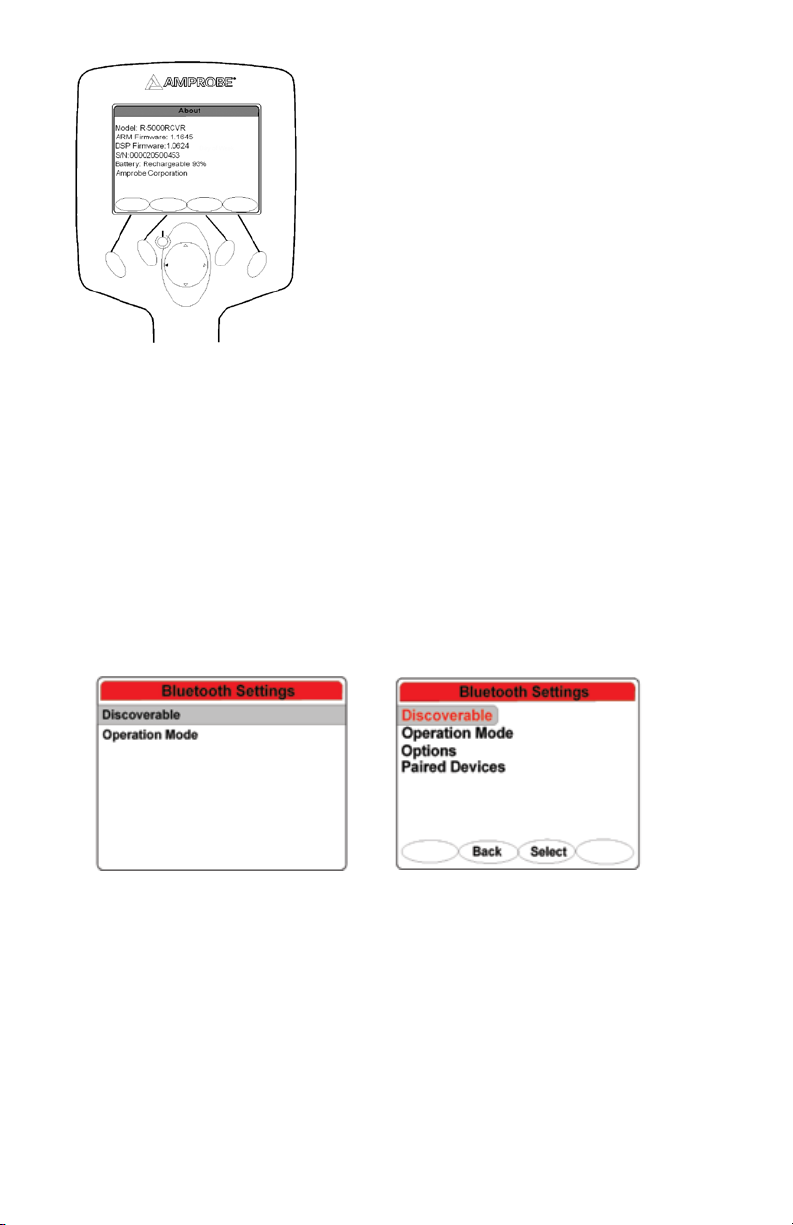
Bluetooth Wireless Interfaces .................................................................................................................................................................. 25
Bluetooth Settings – Discoverable ..................................................................................................................................................... 25
Operation Mode .................................................................................................................................................................................25
Options ................................................................................................................................................................................................ 26
Paired Devices .....................................................................................................................................................................................26
Pairing a Transmitter and Receiver .................................................................................................................................................... 27
Shortcuts Menu ........................................................................................................................................................................................27
Data Logging Menu ................................................................................................................................................................................. 28
R-5000 Frequency System ........................................................................................................................................................................ 30
R-5000 Gain System ............................................................................................................................................................................ 31
R-5000 Volume System ............................................................................................................................................................................. 31
Guidance Compass ...................................................................................................................................................................................31
Center Line Position ................................................................................................................................................................................. 32
Operation ................................................................................................................................................................................................. 32
Applications and principles of direct coupling ....................................................................................................................................... 34
Direct Coupling ................................................................................................................................................................................... 35
Direct Coupling using the SC-5000 Clamp ......................................................................................................................................... 36
Inductive Coupling .............................................................................................................................................................................. 36
Locating Passive Lines (Radio and Power Modes) ............................................................................................................................. 37
3
Page 6

Locating unknown cables ................................................................................................................................................................... 38
Depth and Current Measurements .................................................................................................................................................... 39
Battery Pack (R-5000) ............................................................................................................................................................................... 40
Battery Pack (T-5000) ...............................................................................................................................................................................40
R-5000 Receiver Technical Specifications ................................................................................................................................................ 41
T-5000 Transmitter Technical Specifications ...........................................................................................................................................42
4
Page 7
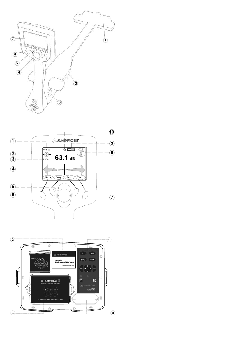
R-5000 Receiver
➊ Detection Sensor
Battery Compartment
➋
Smart Connector
➌
4-Way Navigation Control
➍
ON/OFF Power Button
➎
Soft Keys
➏
Operator Interface
➐
➊ Active Frequency
Signal Select
➋
Auto or Manual Gain
➌
Distance Sensitive Left/Right Guidance Needle
➍
ON/OFF Power Button
➎
Soft Keys
➏
4-Way Navigation Button
➐
Guidance Compass
➑
Battery Indicator
➒
Audio Volume Indicator
➓
R-5000 Operational Interface
T-5000 Top Panel View
Controls
➊
Operational Interface LCD
➋
Battery Compartment
➌
RS232 Serial Port and Fuse
➍
5
Page 8
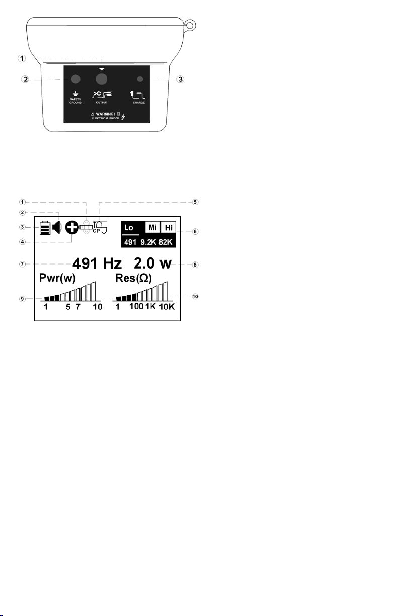
T-5000 Side Panel View
T-5000 Operational Interface LCD
Direct connect or Clamp
➊
Safety Ground
➋
Charger or External 12 Vdc
➌
(External Power supply is not included:
12V, 5.5A, Plug standard:2.1 x 5.5 x 11mm,
center positive)
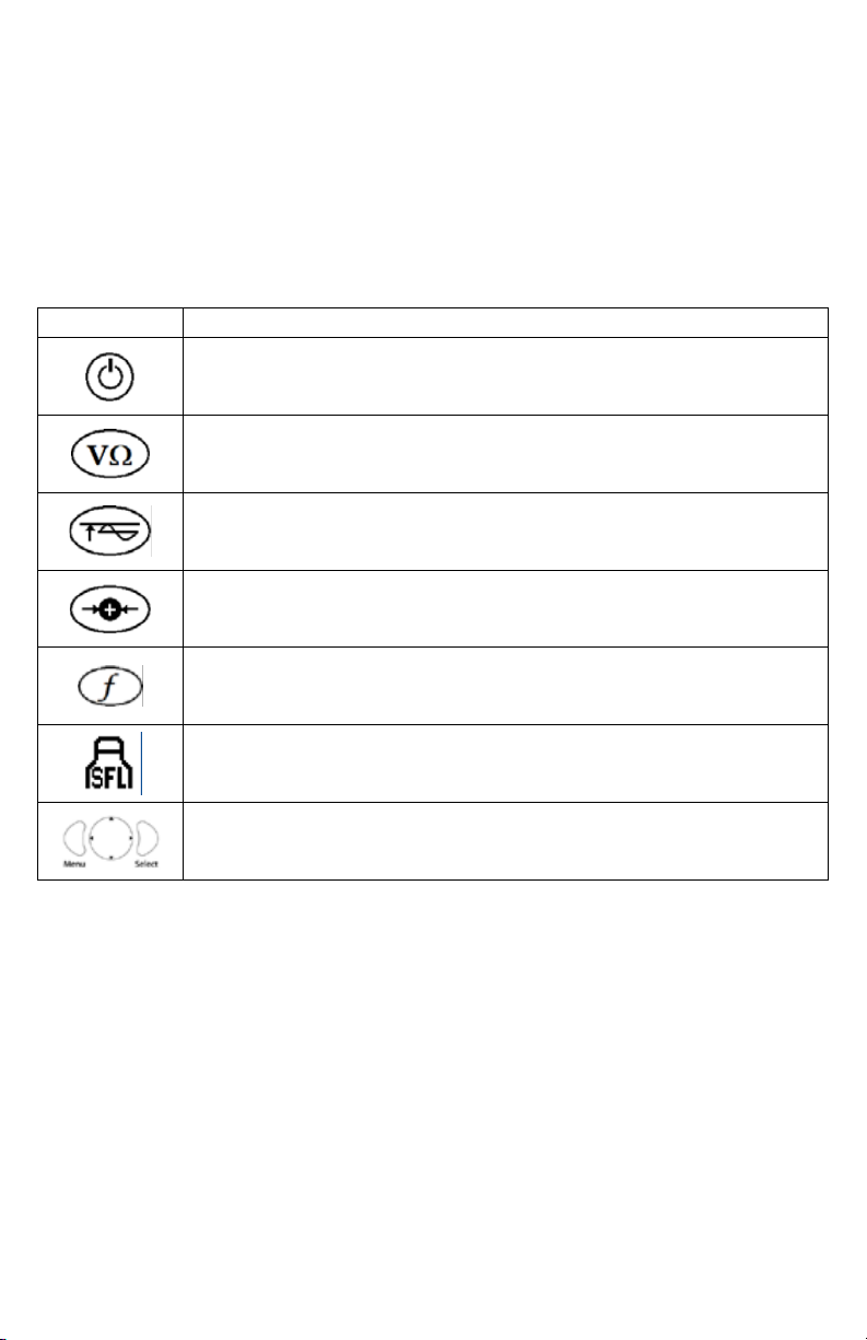
➊ Direct Connection
Audio Volume
➋
Battery Status
➌
Signal Select
➍
Constant Power
➎
Active Frequency Menu
➏
Frequency in use
➐
Power output in use
➑
Power output level
➒
Resistance output level
➓
6
Page 9

INTRODUCTION
The Amprobe AT-5000 is a state-of-the-art utility cable locator precisely designed with many powerful features to provide you
with optimum information about your application.
Having confidence in an instrument is an important part of to use the instrument. All Applications are different and unique. An
understanding of the system’s operation Could mean the difference between several minutes or several hours on the job.
Please read this manual carefully. Take the time to learn how the instrument operates. The operation is user friendly and easy to
learn. Test it in a variety of situations. You will soon have the confidence to use it on a daily basis to solve the problems that were
unsolvable before.
PRECAUTIONS AND SAFETY MEASURES
General
This instrument has been designed in compliance with EN 61010-1:2001 directive. For your own safety and to avoid damaging
the instrument we suggest you follow the procedures hereby prescribed and to read carefully all the notes preceded by the
symbol .
Before and during measurements please be very diligent in following instructions below:
Do not measure voltage or current in wet or dusty places;•
Do not measure in presence of gas, explosive materials or combustibles;•
Do not touch the circuit under test if no measurement is being taken;•
Do not touch exposed metal parts, unused terminals, circuits and so on;•
Do not use the instrument if it seems to be malfunctioning (i.e. if you notice deformations, breaks, leakage of substances, and •
absence of messages on the display and so on);
Use only cables and accessories approved by Amprobe.•
Symbols used in this manual
Important instructions concerning the protection of staff and equipment as well as technical safety within this document are
labeled with one of the following symbols:
Indicates a potentially hazardous situation, which, if not avoided, may result in minor or moderate injury or material
damage.
Indicates a potentially hazardous situation, which, if not avoided, could result in death or serious injury.
Notes have important information and useful tips on the operation of your equipment. Non-observance may result
in incorrect measurement results.
Safety Precautions
This manual contains basic advice for the installation and operation of Amprobe Underground cable locator and accessories.
The manufacturer is not liable for damage to material or humans due to non-observance of the instructions and safety advice
provided in this manual. Therefore, this manual should be provided and reviewed by all personnel associated with the cable
locating equipment.
Safety Practices
Familiarize yourself with all required safety practices of the local utility company, or other owner of the plant before entering an
access area, or connecting an Amprobe transmitter. Ensure that the line is de-energized and out of service, before connecting
the transmitter directly to any conductor. NEVER make a direct connection to a live power cable. Follow the appropriate safety
procedures to avoid the risk of injury if using a clamp on energized electrical or control lines. Pay special attention when using a
locator in high traffic areas.
Intended Application
Safe operation is only realized when using the equipment for its intended purpose. Using the equipment for other purposes
may lead to human danger and equipment damage.
The limits described under the technical data section may not be exceeded.
Malfunction Behavior
The equipment may only be used when working properly. When irregularities or malfunctions appear that cannot be solved
consulting this manual, the equipment must immediately be put out of operation and marked as not functional. Amprobe must
be contacted for technical support and/or service. The instrument may only be operated when the malfunction is resolved.
Dangers when operating with HV:
Special safety attention is needed when operating HV facilities, especially non-stationary equipment. The regulations VDE 0104
about setting up and operation of electric test equipment, i.e. the corresponding EN 50191 as well as country-specific regulations
and standards must be observed.
Safety installations may not be by-passed nor deactivated.
Operation requires a minimum two people whereas the second person must be able to activate the emergency switch in case of
danger.
To avoid hazardous electric charges of metallic parts in the vicinity, all metallic parts must be grounded.
To avoid drawing dangerous arcs, switching should only be done in a de-energized condition.
7
Page 10
The equipment and all accessories must be connected according to applicable standards VDE, EN or DIN as well as countryspecific regulations.
UNPACKING AND INSPECTION
Your shipping carton should include:
1 x R-5000 Receiver
1 x T-5000 Transmitter
1 x CK-5000 Test leads and Ground Stake
1 x Instruction Manual
1 x Carrying case Nylon Bag
T-5000 TRANSMITTER SYSTEM OVERVIEW
Controls
Control Description
Power ON – Push to turn the transmitter ON or OFF. An amber LED illuminates when the transmitter
is ON.
Circuit Condition – Available only in direc t connection mode. Push to toggle through and view the
actual condition of the circuit in volts, milliamps, wat ts, and ohms .
Output Level – Push to change the output level. Push repeatedly or use the left /right navigational
button to increases or decrease the output level.
Signal Select – Push to turn Signal Select ON or OFF for positive line identification.
Frequency Select – Push to toggle through the active frequencies.
Sheath Fault Locate (SFL) – Push to turn the SFL feature ON or OFF. A red LED illuminates when the
feature is ON.
4-Way Navigation Control – Push to select and navigate through the operational menu screens
and active frequenc y menu.
8
Page 11
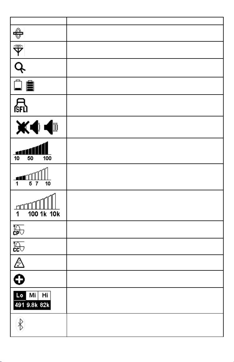
T-5000 LCD Display Indicator Icons
Icon Description
Direct Connection Mode - When displayed, direc t connection operation is active.
Induc tive Connection Mode – When displayed, inductive connection operation is active
Clamp – When displayed, a clamp is connec ted to the transmitter
Battery Status – Displays the available battery charge capacity from low to full.
Sheath Fault Locate– W hen displayed, sheath fault locate feature is active
Audio Volume – Displays the audio volume level from off to high
% Power Output – Displays the output power percentage in SFL or induction mode
(clamp and internal antenna).
Power Output Level – Displays the output power in Wat ts (W) in direct connection mode.
Resistance (Ω) Output Level – Displays the loop resistance graph
Constant Power Output – When displayed, constant power feature is active.
Constant Current Output - When displayed, constant current feature is active.
Live Voltage Warning – When displayed, the Power Protection feature is ON.
Signal Select – When displayed, signal select modulation is active.
Active Frequency Menu – Displays the active frequencies.
Indicates an active Bluetooth connection.
9
Page 12
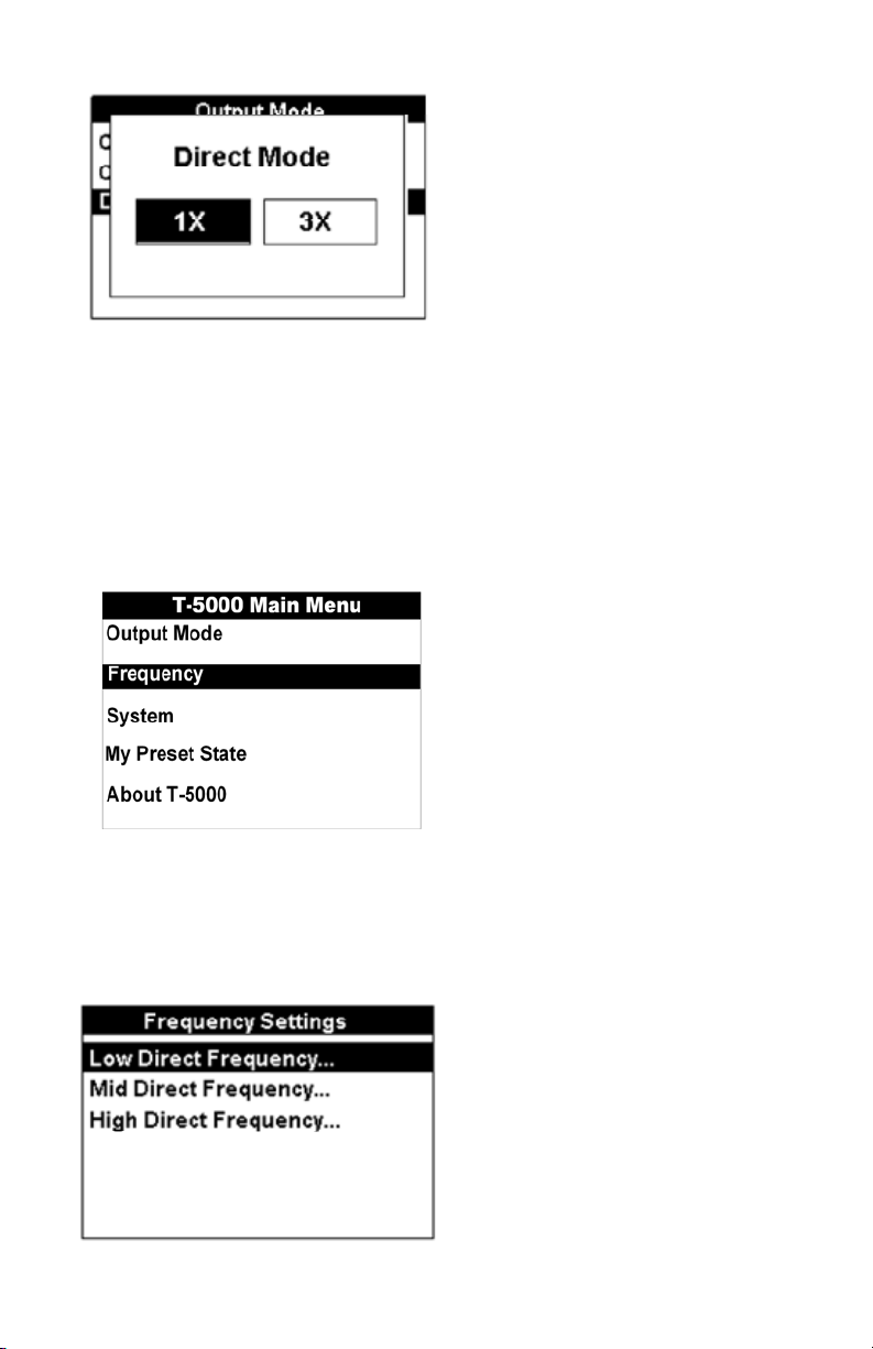
T-5000 Transmitter Main Menu
The Transmitter includes five (5) selectable menus for operation.
The desired menu is selected using the three-button navigational keypad.
Push Menu. •
Push the up/down arrows to select the desired menu option.•
Push Select to open the desired menu screen. •
Push Menu to return to the operational display screen. •
Output Mode Menu
The T-5000 Transmitter output mode menu allows the operator to configure the desired output settings – constant current,
constant power, or direct mode.
The desired output mode is configured using the three-button navigational keypad.
Push the • up/down arrows to select the desired output.
Push • Select to activate the desired output. The transmitter automatically returns to the operational display screen and the
selected display indicator icon is visible.
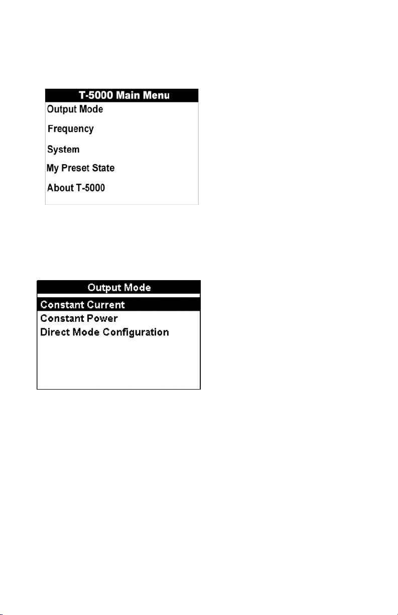
Output Mode Menu – Direct (Conductive) Mode Configuration
The T-5000 Transmitter allows the operator to configure up to three active frequencies simultaneously in direct (conductive)
connection mode.
The desired direct mode is configured using the three-button navigational keypad.
Push the left/right arrows to select the desired quantity of active frequencies available for use simultaneously.
10
Page 13
Push Select to activate the desired configuration. The transmitter displays the active configuration and returns to the operational
display screen.
Frequency Menu
The T-5000 Transmitter frequency menu allows the operator to configure the desired active frequency (ies). Different menu
screens appear depending upon the connection mode – direct (conductive), inductive coupling with clamps, or inductive
antenna. The operator can then select the desired available frequencies.
Sheath fault locating (SFL) frequency selection is discussed separately.
The desired menu is selected using the three-button navigational keypad.
Push Menu.
Push the up/down arrows to select the desired menu option.
Push Select to open the desired menu screen.
Push Menu to return to the operational display screen.
Frequency Menu - Direct (Conductive) Connection Mode
Direct (conductive) connection mode allows the operator to configure up to three active frequencies. The operator is limited to
selecting one frequency in each frequency menu – low, mid, and high.
The desired frequency settings menu is configured using the three-button navigational keypad.
Push the • up/down arrows to select the desired option.
Push • Select to open the desired frequency settings menu.
Push • Menu to return to the previous screen.
The desired frequency is configured using the three-button navigational keypad.
11
Page 14
Push the • up/down arrows to select the desired frequency.
Push • Select to activate the desired frequency.
Push the • Signal Select
frequency is marked with an X. An operator can activate the Signal Select feature for all available frequencies even if the
frequency is not currently selected for use.
Repeatedly pushing the • output level control
the selected frequency. The output can be increased in 1X, 2X, 5X, or 10X increments up to 1A or 10W, respectively.
Push Menu or Select to return to the frequency settings menu screen.•
Push Menu to return to the operational display screen.•
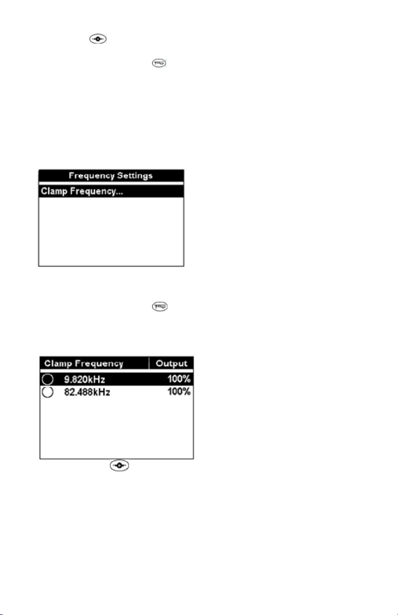
Frequency Menu - Inductive Coupling with Clamps
Inductive coupling with Amprobe clamps SC-5000 enables the operator to induce a signal onto the target conductor. It allows the
operator to configure one active frequency for operation – 9.82 kHz or 82.488 kHz.
Frequency Menu – Inductive Coupling with the Signal Select™ Clamp
The desired clamp frequency is configured using the three-button navigational keypad.
Push Select to activate the desired frequency.•
Push Menu to return to the frequency settings menu.•
The desired frequency is configured using the three-button navigational keypad.
Push the • up/down arrows to select the desired frequency.
Push • Select to activate the desired frequency.
Repeatedly pushing the • output level control
the selected frequency. The applied output can be increased incrementally by 10%, 25%, 50%, 75%, or 100% of maximum
power.
Push • Menu or Select to return to the frequency settings menu screen.
Push • Menu to return to the operational display screen.
button to activate or deactivate the Signal Select feature if available. The activated Signal Select
button allows the operator to configure the output current or power of
button allows the operator to configure the output current or power of
Push the Signal Select button • to activate or deactivate the Signal Select feature. The Signal Select icon is displayed on
the operational display screen when activated.
Frequency Menu - Inductive Antenna Connection Mode
Inductive antenna connection mode enables the operator to select one active frequency.
The desired frequency settings menu is configured using the three-button navigational keypad.
Push • Select to open the inductive frequency settings menu.
12
Page 15
Push • Menu to return to the previous screen.
The desired frequency is configured using the three-button navigational keypad.
Push the up/down arrows to select the desired frequency. •
Push Select to activate the desired frequency. •
Repeatedly pushing the output level control •
frequency. The applied output can be increased incrementally by 10%, 25%, 50%, 75%, or 100% of maximum power.
Push Select to return to the inductive frequency menu screen. •
Push • Menu to return to the operational display screen.
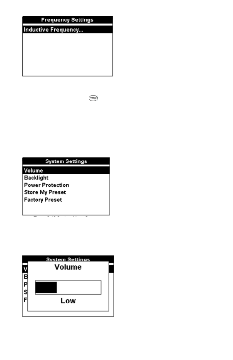
System Settings Menu
The T-5000 Transmitter system menu allows the operator to configure the desired system settings.
The desired system settings menu is configured using the three-button navigational keypad.
Push the • up/down arrows to select the desired option.
Push• Select to open the system settings menu option.
Push • Menu to return to the previous screen.
button allows the operator to configure the output power of the selected
System Settings Menu – Volume
Selecting Volume allows the operator to set the transmitter volume level: OFF, low, medium, or high.
The desired volume level is configured using the three-button navigational keypad.
Push the left/right arrows to select the desired volume level.•
Push Select to activate the desired volume level. The transmitter automatically returns to the operational display screen and •
the selected display indicator icon is visible.
System Settings Menu – Backlight
Selecting Backlight allows the operator to set the transmitter operational display backlight ON – always ON or Auto (during
configuration or pressing control buttons).
The backlight is configured using the three-button navigational keypad.
13
Page 16

Push the left/right arrows to select the desired setting. •
Push Select to activate the desired setting. The transmitter automatically returns to the operational display screen.•
System Menu – Power Protection
Selecting Power Protection allows the operator to set the transmitter’s Power Protection feature – always On or Auto
(recommended).
The Power Protection feature is configured using the three-button navigational keypad.
Push the left/right arrows to select the desired setting. •
Push Select to activate the desired setting. The transmitter automatically returns to the operational display screen and the •
selected display indicator icon is visible.
System Menu – Store My Preset
Selecting Store My Preset allows the operator to save the transmitter’s current configured operational conditions – No or Yes, as
the preset state.
The Store My Preset feature is configured using the three-button navigational keypad.
Push the left/right arrows to select the desired setting.•
Push Select to activate the desired setting. The transmitter automatically returns to the operational display screen.•
System Menu – Factory Preset
Selecting Factory Preset allows the operator to reset the transmitter’s operational conditions to the recommended factory
settings.
The Factory Preset feature is configured using the three-button navigational keypad.
Push the • left/right arrows to select the desired setting.
14
Page 17

Push • Select to activate the desired setting. The transmitter automatically returns to the operational display screen.
My Preset State Menu
The T-5000 My Preset State allows the operator to return the transmitter’s operational conditions to the configured and saved
preset state by selecting – No or Yes.
The My Preset State feature is configured using the three-button navigational keypad.
Push the left/right arrows to select the desired setting. •
Push Select to activate the desired setting. The transmitter automatically returns to the operational display screen.•
About T-5000 Menu
The About T-5000 menu allows the operator to view the transmitter’s serial number, hardware, and firmware information.
Push Menu to return to the previous screen.•
Sheath Fault Locating (SFL) Optional Accessory A-5000
The Sheath Fault Locating (SFL) feature is available in Direct (Conductive) Connection mode only.
Push the SFL button, •
Frequency selection is not configurable through the frequency menu screen.
Frequency selection: 9.82 kHz or 82 kHz, is activated by pressing the frequency button,
The active frequency is displayed on the operational display screen.
, to activate operation.
.
15
Page 18
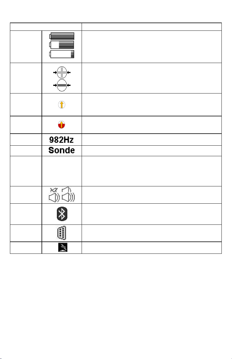
R-5000 LCD Display indicators
The color graphical display shows intuitive icons used to aid in accurate locating by the user.
Display Icon Description
Battery Level
Signal
Select™
Guidance
Compass™
Distortion
Alert™
Frequency
Locate Mode
Signal Gain
Mode
Speaker
Volume
Bluetooth
Auto
Man
Displayed as a continuous level from a full 100% charge to 0%.
Displayed when activated in direct (conductive) connection or Signal Select
Clamp mode. This icon alerts the user if the receiver detects Signal Select
modulation.
A single graphical icon that implements three tools aiding locating accuracy –
signal select, distortion alert, and line guidance.
The Distortion Alert, displayed as a red-filling or emptying circle, denotes when
a non-ideal magnetic field is detected.
The active frequency, or the passive band name (power or RF), is always
displayed on the top left of the display.
In Sonde locate mode, the active mode is displayed on the top left of the
display. Otherwise, line locate mode is active.
Indicates Auto or Manual signal strength mode. In auto mode, signal strength
is measured in decibels (dB). The auto gain mode can be readjusted pressing
the 4-way navigation button up. Manual gain is displayed in a linear scale from
000 to 999. The manual gain can be increased or decreased by pressing the
4-way navigation button right or left, respectively. Manual gain is displayed in
a linear scale from 000 to 999.
Indicates the speaker volume setting - from off to high.
Indicates an active Bluetooth connection.
RS232
GPS
Appears when a host serial cable is connected to R-5000 receiver.
Indicates the receiver can receive signals from 3 or more satellites (optional).
Not available for AT-5000
16
Page 19

R-5000 MENU SYSTEM
The receiver’s menu system includes five (5) active selectable menus for configuring the AT-5000. The Bluetooth menu is not
available for the R-5000.
Push the <Menu> soft key from the R-5000 operational interface to access the main menu.•
Use the 4-way navigation button to select the desired menu option. The selected menu is highlighted on the interface as well •
as labeled at the top of the display.
Main Menu Selection
Frequency Selection
The frequency menu allows you to choose one of the five frequency ranges available: Low, Mid, High, Power, and RF.
Low Frequency:491Hz,577Hz,640Hz,982Hz
Mid Frequency: 8.192kHz,9.82kHz,35kHz
17
Page 20

High Frequency: 82kHz
Power: 50Hz, 60Hz
RF: ALL RF frequencies
Push the 4-way navigation button (up/Down/Left/Right) to highlight the frequency menu.•
Push the Select button to open the frequency menu•
Push the 4-way navigation button (up or down) to select Low, Mid, High, Power, RF frequency range.•
Push the 4-way navigation button(Left or right) to move to the frequency values•
Push the 4-way navigation button(up or down) to toggle through the values•
Push the Select button to activate or deactivate a value•
Push Use button to confirm your choices•
Push Back button to return to the previous menu interface or cancel the changes•
NB. Deactivating frequencies does not permanently remove them from the R-5000 receiver. Access the frequency menu to
reactivate them.
Activated frequencies can be selected from the operational interface by Pushing the <Freq> soft key. Selecting fewer
frequencies allows faster toggling between frequencies from the operational interface.
18
Page 21
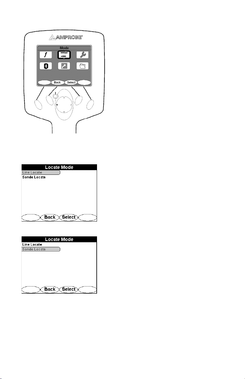
Mode Menu
Two locate modes are available: Line and Sonde
Push the 4-way navigation button (up/Down/Left/Right) to highlight the Mode menu.•
Push the Select button to open the Mode menu•
Push the 4-way navigation button (Up or Down) to highlight a desired locate mode.•
Push Select button to activate the desired locate mode•
Push Back to return to the previous menu interface•
Line Locate1.
Line locate is used to trace the cable using the T-5000 signal transmitter
Sonde Locate2.
Sonde Locate is used to trace the cable using the M-5000 sonde transmitter. The R-5000 receiver automatically adjusts
its depth calculation algorithms to reflect the differences between a line radiating a transmitter signal and the signal
generated by a sonde transmitter.
19
Page 22

SETTINGS MENU
The following options are available: Personalise, Audio, Initial Setup, Tools, Supervisor, Preset State, and About.
Push the 4-way navigation button (up/Down/Left/Right) to highlight the Mode menu.•
Push the Select button to open the Settings menu•
Push the 4-way navigation button (Up or Down) to highlight a desired setting mode.•
Push the 4-way navigation button (right) to highlight an option•
Push the 4-way navigation button (Up or Down) to toggle through the options.•
Push Select button to activate or deactivate an option•
Push Back to return to the previous menu interface•
Personalise
The personalize menu gives you the option to control the distortion number, the distortion graph, the signal select, the guidance
compass, and the peak hold. Check an option to activate it and uncheck an option to deactivate it.
20
Page 23
Audio
The Audio menu controls the R-5000 receiver audio output characteristics.
The following options are available:
Volume: Off, Low, Med, High•
Sound: None, LR (Left/Right audio guidance), AM(Amplitude modulated audio mode mapped to Peak signal strength)•
Key-Sound: On, Off•
Initial Setup
The Initial Setup section of the Settings menu controls the following receiver features:
Backlight: Off, 60s, On•
Units: US, Metric•
Auto-Off: Off, On•
Freq: Last used,512Hz,577Hz,640Hz,982Hz,8.192kHz,9.82kHz,35kHz,82kHz•
Line Freq: 60Hz,50Hz•
Language: English, Español, Français, Deutsch, Polski•
21
Page 24

Tools
The tools section of the setup menu controls the following receiver features: Display Clock, Time Zone, Daylight Saving, and GPS
Status.
Display Clock
Displays the clock status.
Push Back button to return to previous menu•
Time Zone
Displays the available time zones around the world
Push 4-way navigation button (Up or Down) to highlight a time zone•
Push Select button to activate a time zone•
Daylight Savings
Allows you to adjust the clock for daylight savings
22
Page 25

Push Yes to activate daylight savings•
GPS Status: NOT AVAILABLE WITH AT-5000
Supervisor
Allows you to lock and unlock the settings.
Push the 4-way navigation button (right) to highlight UNLOCK•
Push Select button to enter access code•
Push the 4-way navigation button (Up/Down/Right/Left) to enter your access code.•
Push submit to unlock the settings•
Preset State
Allow you to reset the R-5000 receiver to its initial state.
23
Page 26
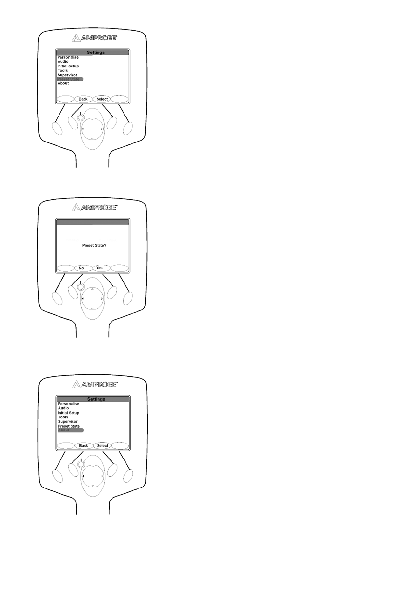
Push Select to open the preset state menu•
Push YES to reset the device to its initial state•
Push no to cancel and return to previous menu•
About
Allows you to see the information about the firmware version, Serial number, Battery status etc…
Push Select button to enter the About screen•
24
Page 27
Push any button to return to the previous menu•
BLUETOOTH WIRELESS INTERFACES
The AT-5000 Bluetooth wireless feature allows the operator to transmit data from the T-5000 transmitter to the R-5000 Receiver
or another Bluetooth-enabled device such as a computer.
Data and digital photos can be saved in memory and transferred via Bluetooth wireless communication to laptop computers or
PCs. The reverse is also available - locate ticket information and digital photos may be loaded into the R-5000 memory.
To access the Bluetooth menu, use the 4-way navigation button (R-5000) or the three-button navigational keypad (T-5000) to
highlight the Bluetooth icon. The chosen menu is also labeled at the top of the menu screen.
Press the <Select> soft key to open the desired menu screen. Press <Back> to return to the operational interface. Use the 4-way
navigation button (R-5000) or the three-button navigational keypad (T-5000) to select another menu.
Bluetooth Settings – Discoverable
Select Discoverable on the T-5000 transmitter or the R-5000 receiver to configure both the transmitter and the receiver’s wireless
Bluetooth transmission feature. If activated, the transmitter or the receiver automatically searches for surrounding Bluetoothenabled devices.
The Discoverable state feature is configured using the three-button navigational keypad on the T-5000 or the 4-way navigation
button on the R-5000. Press the up/down and left/right arrows to select the Discoverable option. Press <Select> to activate the
desired setting. The transmitter or the receiver automatically returns to the operational display screen.
T-5000 Discoverable R-5000 Discoverable
Operation Mode
The operation mode sets the data transmission selection – Bluetooth, RS232, or either option. Selecting Auto allows receiver
connections via the RS232 cable or via Bluetooth. If the RS232 cable is connected, Bluetooth is not available. Selecting ON allows
connection with Bluetooth only. Selecting OFF turns the Bluetooth feature off. The default setting is Auto for the R-5000.
Use the 4-way navigation button to move up and down the Bluetooth Settings list. Use the 4-way navigation button to move
right and highlight the options. Press the <Select> soft key to choose the option. Press the <Back> soft key to return to the
previous interface.
25
Page 28

T-5000 Bluetooth Operation mode R-5000 Bluetooth Operation mode
Options
Selecting Factory Preset resets certain internal Bluetooth settings to factory defaults.
Make sure the R-5000 receiver Bluetooth Setting is in the OFF position before entering any telecommunications central office or
other telecommunications data transmission infrastructure.
R-5000 Options mode
Paired Devices
The paired devices menu allows the user to mate up to six transmitters to a single receiver. If a receiver is within 30 ft. (9 m) of
a transmitter and Bluetooth transmission is ON for both instruments, the receiver logs the output power conditions and active
frequencies every 30 sec. Logged data is stored in the receiver memory until the receiver is synchronized with a PC or a web
server. The blue LED emits during active transmission.
Use the 4-way navigation button to move up and down the Bluetooth Settings list. Use the 4-way navigation button to move
right and highlight the options. Press the <Select> soft key to choose the option.
Press the <Back> soft key to return to the previous interface.
26
Page 29

Pairing a Transmitter and Receiver
To pair a transmitter and receiver, make sure both instruments have the Bluetooth feature ON. Press the <Select> soft key to
initiate discovery of the transmitter. Press the <Back> soft key to return to the previous interface.
Upon completion of the transmitter discovery, the receiver displays the paired transmitter. The last four digits of each transmitter
denote the unique identity of each paired unit.
To remove a paired transmitter, use the 4-way navigation button to highlight the desired unit. Press the <Clear> soft key to erase
a paired transmitter from the list.
To remove all paired devices, use the 4-way navigation button to highlight Clear all devices. Press the <Clear> soft key to erase
all paired devices.
SHORTCUTS MENU
The following shortcuts are available to access from the main screen: Adjust Volume, Backlight Power and Ticket Management.
Push the 4-way navigation button (up/Down/Left/Right) to highlight the Shortcuts menu.•
Push Select to open the shortcuts menu•
Push the 4-way navigation button (Up or Down) to toggle through the options
Push Select to activate an option
27
Page 30
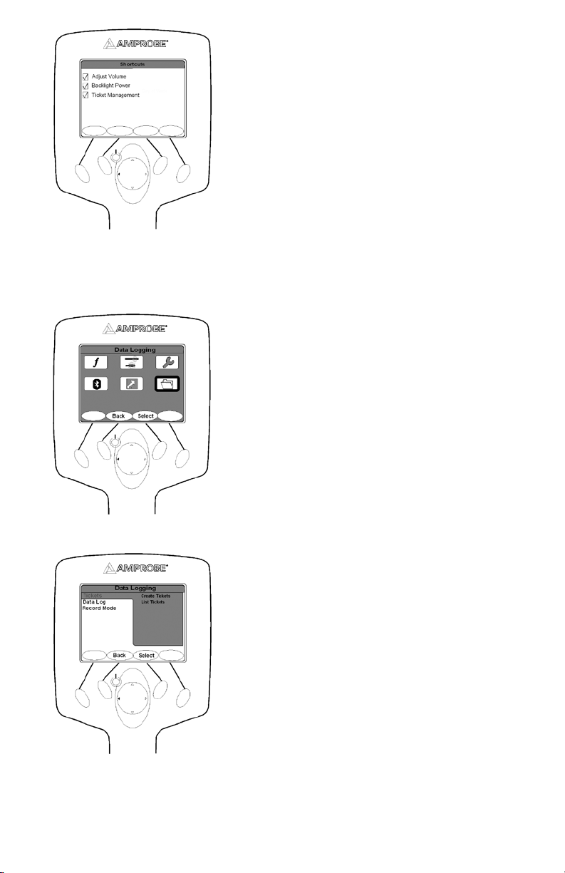
DATA LOGGING MENU
The Data Logging feature provides data ticket management services for the AT-5000.
Three selections are available in this menu: Tickets, Data log, and Record Mode.
Push the 4-way navigation button (up/Down/Left/Right) to highlight the Data Logging menu.•
Push Select button to open the Data Logging menu•
Push the 4-way navigation button (Up or Down) to toggle through the options
Push Select button to activate an option
Tickets
Two options are available on the tickets menu – creating tickets and List tickets.
Push the 4-way navigation button (Right) to highlight a desired option.•
Push Select button to open the menu•
Push Back button to return to previous menu•
28
Page 31

Create Tickets
Create Ticket generates a new ticket on the R-5000 receiver. A notification that a new ticket is being created appears on the
screen for a few moments and the screen returns to the Data Logging Tickets window.
Push the 4-way navigation button (Up or Down) to highlight create•
Push Select Button to create a new ticket•
List Tickets
All tickets in memory will be listed along with the menu option: Information / Activate / Close / Enter Response.
Push the 4-way navigation button (Up or Down) to highlight List Tickets•
Push Select Button to open the list of tickets•
Information
The Ticket Information header indicates the open or closed status of a ticket.
Push Active button to open the ticket. •
Push Close button to close the ticket •
Push Back button to return to the previous menu.•
Activate
Selecting Activate opens a ticket to store data
Push 4-way navigation button to highlight a. Activate
Push Select to open the ticketb.
Push Back to return to previous menuc.
Close
Selecting close deactivate a ticket and no data will be stored under that ticket. The ticket name will be stricken through denoting
its closure.
Data Log
Data Log gives you the options to access the log memory and the images stored in the R-5000 memory.
29
Page 32

Log Memory
Push the 4-way navigation button to highlight Log Memory•
Push Select button to open Log Memory•
Pictures
Selecting Pictures displays the name and size of all Locate Images in memory. Images are recorded in chronological order. No
viewing capability is currently available on the receiver LCD.
To log a picture into the receiver memory, a Bluetooth-ready camera must be ON and ready for transmission. The R-5000 receiver
must also be set on discoverable prior to transferring the image. The captured image can then be transmitted through the
camera’s send function. The receiver’s blue LED will emit confirming that the Bluetooth connection is active.
Record Mode
Record Mode allows the user to select the data logging format. Two choices are available for selection - on Depth or on Depth
+ Timer.
Push the 4-way navigation button (Up or Down) to highlight an option.•
Push Select button to activate or deactivate an option•
Push Back button to return to previous menu•
R-5000 FREQUENCY SYSTEM
The active frequency or the passive band name (power or RF), is always displayed on the top left of the R-5000 receiver
display. When the frequency soft key is used to change frequency, the display is updated as well.
Push Freq button to select the frequency to use.•
30
Page 33

R-5000 Gain System
Push GAIN button once to switch from manual and Automatic gain•
Push the 4-way navigation button(left or Right) to decrease or increase the gain•
Push Gain button twice successively to switch between Left/Right guidance mode and Peak Null mode.•
In peak mode, a graphical peak is displayed. Signal strength is represented numerically in dB and graphically with a blue •
signal level. As the signal strength increases, the blue bar graph begins to peak towards the top of the graph.
As the peak position is identified and the receiver is used in a swinging motion, the peak position is displayed graphically by the
green bar graph then slowly decreases as the signal strength changes.
R-5000 VOLUME SYSTEM
The volume setting has four levels available: OFF, LOW, MED, and HIGH
Push the VOL button to switch from OFF
GUIDANCE COMPASS
The guidance compass indicator provides additional information about the cable you are tracing:
The direction of the signal is indicated by the orientation of the orange arrow inside the guidance compass indicator. A •
FORWARD pointing arrow indicates that the receiver detects a signal flowing away from the transmitter. A DOWNWARD
pointing arrow means that the signal is a return signal flowing back towards the transmitter.
Changes in the direction of the line relative to the orientation of the receiver are indicated by the signal direction arrow •
moving away from the North or South position.
, LOW , MED and HIGH
31
Page 34

The presence of bleed over signals is indicated by the RED color filling the inside of the guidance compass indicator.•
CENTER LINE POSITION
The Left/Right display is tremendously useful in refining the precise location of the target line. The vertical black bar represents
the underground utility cable. Follow the vertical bar to determine the position of the cable. When shown at centerline it
indicates that the R-5000 Receiver is on top of the target.
Signal Select
The direction of the signal in the targeted line is determined by analyzing the sign of the demodulated Signal Select signal.
When the R-5000 receiver is positioned over a signal that carries an inverted field (i.e., one in which the phase is –180° from the
expected, the Guidance Compass points down, as shown below for a line that is bonded to the target line and carries return
current.
OPERATION
Decide which mode of operation to use for your application1.
: Transmitter’s signal is emitted through the integrated antenna and is thereby inductively coupled with any
Induction
metallic lines located within a certain radius.
Base Frequencies (Hz): 9.82k, 82k a.
32
Page 35

Place the T-5000 transmitter on the site to be searched. b.
Direct Connection
connected to the jacks on the front panel of the transmitter. Transmitter clamps, alligator clips or power socket adapters
(for example) may be used to connect the measurement cable to the lines.
: Transmitter’s signal is directly coupled with a metallic line via the measurement cable which is
Connect the T-5000 transmitter to the line to be located using the desired method for your application.a.
Connecting directly to the target utility provides a higher field strength 1.
North America Base Frequencies (Hz): 491, 982, 8.44k, 9.82k, 35k, 82k, 83k 2.
International Base Frequencies (Hz): 491, 577, 640, 982, 8.192k, 8.44k, 9.82k, 35k, 82k, 83k 3.
Clamp (induction) b.
Connecting with SC-5000 clamp 1.
Base Frequencies (Hz): 9.82k, 82k 2.
Connect the T-5000 Transmitter to the Conductor (for direct connection). 2.
With the transmitter OFF, plug the conductive attachment located on the side panel. a.
Stretch the black lead 90 degrees away from the conductor. Push the ground rod as deeply as possibly into the earth. b.
Connect the black lead to the ground rod.
Clamp the red lead to the target conductor, ensuring good metal-to-metal contact.c.
Turn on the T-5000 Transmitter. 3.
Push the Power ON button to turn on the transmitter. An amber LED will illuminate. The T-5000 introduction screen is
displayed for two seconds before displaying the operational display.
Select Frequency 4.
The T-5000 saves the selected frequencies from the last locate.a.
Push the 4-way navigation button (up/down) to change from Lo/Mi/Hi frequency menu. b.
Push the frequency button to change the active frequency displayed. c.
To change the quantity of active frequencies available for locating, d.
Push Menu button. 1.
Push the 4-way navigation button (up/down) to select Output Mode from the T-5000 Main Menu. 2.
Push Select. 3.
Push the 4-way navigation button (up/down) to select Direct Mode Configuration. 4.
Push Select. 5.
Push the 4-way navigation button (left/right) to select 1x or 3x. 6.
Push Select. 7.
Select Power Setting. 5.
The T-5000 has two output choices: a.
Constant Current
Constant Power (the factory default to maximize field strength and battery life)
To change the output setting:b.
Push Menu 1.
Push the 4-way navigation button (up/down) to select Output Mode from the T-5000 Main Menu. 2.
Push Select 3.
Push the 4-way navigation button (up/down) to select the desired output mode. 4.
Push Select. 5.
Turn On the R-5000 Receiver6.
Select the Frequency to use for the application. Refer to R-5000 Frequency system.7.
Determine the Center line position. Refer to R-5000 Signal Select.8.
Observe the guidance compass. Refer to R-5000 Guidance Compass.9.
Start tracing10.
Hold the R-3500 receiver in an upright position in front of you as close to the ground as possible. 11.
Receiver in line with the conductor
Maximum signal strength
33
Page 36

Receiver perpendicular to the conductor minimum signal strength
APPLICATIONS AND PRINCIPLES OF DIRECT COUPLING
Single-wire cables or pipes (with or without insulation against ground)1.
The distance between the grounding rod and the ends of the connected lines should be as great as possible because return
current tends to flow through the earth into adjacent lines, which could result in their path being followed.
Single-wire cable with metallic screen and ground insulation2.
Short circuit between internal conductor and screen at the end of the cable with ground at the beginning and end of the
cable as well.
Failure to make the connection as shown will result in current cancellation from the internal conductor and the return current
in the screen. Under certain circumstances this can prevent the cable from being detected.
34
Page 37

Multiple-Wire Cable (Internal conductor connected or disconnected) with metallic screen and grounding insulation3.
Metallic Conduit (With or Without Insulation)4.
The grounding rod and the conduit should be spaced as far apart as possible. Under certain circumstances, optimum positioning
of the grounding rod may require several attempts.
If a return wire is available5.
The spacing of the return wire should correspond to at least 10 times the depth of the line being located.
Pair of wires (with or without screen) with short circuit at the end of the cable6.
For twisted cable pair (with a length of lay of the twist greater or equal to the laying depth), the orientation of the cable can
be easily determined.
Adjacent lines which are horizontal to each other Minimum of the reception signal
Lines situated on top of each other vertically Maximum of the reception signal
Direct Coupling
Connect the red test lead of the T-5000 transmitter with the conductor to be traced1.
Connect the black test lead of the T-5000 transmitter to ground using the grounding rod. Alternatively the black test lead 2.
may be clipped to the rim of a valve box or manhole cover.
Switch the T-5000 on3.
Select the mode of signal transmission4.
Switch the R-5000 Receiver on5.
35
Page 38

Begin to trace the cable from the point of application about 50-FT (15m) away6.
Move slowly over the cable. Decrease or increase the sensitivity as needed7.
Direct Coupling using the SC-5000 Clamp
Plug the SC-5000 clamp into the T-5000 transmitter connection socket1.
Place the clamp around the pipe or cable2.
Switch the T-5000 transmitter on3.
Set the T-5000 transmitter to the desired signal transmission4.
Switch the R-5000 Receiver on5.
Set the R-5000 Receiver to the desired signal reception6.
Begin to trace the cable from the point of application about 15m away7.
Inductive Coupling
1. Position the T-5000 transmitter above the presumed cable
2. Switch the T-5000 transmitter on
3. Set the T-5000 transmitter to the desired signal transmission mode
4. Switch the R-5000 receiver on
5. Set the R-5000 receiver to the desired signal reception mode
6. Begin to trace the line from the transmitter at least 15m away.
36
Page 39

7. Make sure that a distance of at least 50-FT (15m) is always maintained between the receiver and transmitter in order to
prevent the coupling of the transmitter’s signal through the air.
Locating Passive Lines (Radio and Power Modes)
The R-5000 Receiver can locate passive cables that carry radio signals in the frequency range between 15 kHz and 23 kHz as well
as power signals between the range of 50 Hz and 60 Hz without the help of the T-5000 Transmitter.
Turn the R-5000 Receiver on1.
Select radio mode or power mode. 2.
Set the sensitivity to maximum3.
Sweep the area using a grid pattern as shown below4.
Adjust the sensitivity to pinpoint the conductor5.
37
Page 40

Rotate the R-5000 to find the maximum response6.
Locating unknown cables
Set the T-5000 Transmitter to inductive mode. 1.
Set the R-5000 Receiver to inductive mode.2.
38
Page 41

Start sweeping the area with the R-5000. Keep the receiver 50-FT (15m) apart from the transmitter.3.
Adjust the sensitivity of the R-5000 as needed4.
When a conductor is located, pinpoint the strongest signal and mark the location5.
Repeat steps 1 and 2. Move the transmitter at least 3.3-FT (1m) and 90-degree from the initial position.6.
Repeat the process until the right cable is detected. 7.
Depth and Current Measurements
When the receiver is located directly over the centerline (the left/right position is at the null), the Depth button (“down” section
of 4-way navigation key) can be used to estimate both the depth and current of the target line. The receiver must be at rest,
and held in a vertical position with the tip on the ground. At this position, the audio output is silent, indicating that the receiver
is at the centerline.
When the Depth button is pushed, the receiver averages the signal strength for a few seconds and displays the results.
Push the 4-way navigation button (down) to measure the depth and current•
39
Page 42

BATTERY PACK (R-5000)
The R-5000 receiver is powered by a high-capacity alkaline battery pack or a Li-ion rechargeable battery pack. See figure below.
Battery Pack Legend
a. Battery Lock
Recharging Receptacle
b.
(Power supply is not included. 12V, 5.5A. Plug adapter standard:2.1 x 5.5 x
11mm, center positive.)
Replacing the Battery Pack. R-5000
Twist the battery pack lock counter-clockwise and pull it toward you1.
Release the lock on the battery pack door by pushing it downward2.
Grab the battery pack door on the sides and pull it toward you3.
Remove the old batteries and replace them with new batteries as indicated on the side of the battery pack4.
Close the battery pack door and activate the lock by pushing it upward5.
Insert the battery pack6.
Twist the lock clockwise to secure the battery pack7.
BATTERY PACK (T-5000)
The R-5000 receiver is powered by a high-capacity alkaline battery pack or a Li-ion rechargeable battery pack. See figure below.
Replacing the Battery Pack. T-5000
Twist the battery pack locks counter-clockwise and pull it toward you1.
Remove the old batteries and replace them with new batteries as indicated on the top of the battery pack2.
Insert the battery pack3.
Twist the pad locks clockwise to secure the battery pack4.
Recharging the Battery (Li-Ion)
The battery pack Li-Ion can be recharged while seated inside the receiver body.
To recharge the battery pack:
Make sure recharging of the receiver battery occurs at room temperature. Charging the battery at low and high ambient 1.
temperature will affect how many charge cycles the battery can withstand and might cause other battery damage.
Excess heat can damage batteries, causing a rupture or ignition. Do not place batteries near fire, heat, or in direct sunshine.
Attach the battery charger plug to the charging jack of the Li-ion battery pack. 2.
Plug the power supply into the electrical outlet.3.
The recharging time for a fully discharged battery pack is approximately 8 hrs.4.
The battery pack can also be recharged via the 12VDC vehicle adapter.
40
Page 43

Batteries contain hazardous material that may be harmful to the environment. Dispose used batteries sensibly. Follow local
recycling guidelines for disposal of similar material.
R-5000 RECEIVER TECHNICAL SPECIFICATIONS
Active Frequencies (Hz)
Passive Frequencies (Hz)
Depth Display Accuracy
491, 982, 8.44k, 9.82k, 35k, 82k, 83k (North America)
491, 512, 577, 640, 982, 8k, 8.44k, 9.82k, 35k, 65.5k, 82k, 83k
50, 60, 100, 120, RF (14k-21k)
Extended and special frequency sets available
0-10ft: ±(5%+2”) under ideal field conditions
10-20ft: ±10% under ideal field conditions
Depth Range Maximum 20ft (600 cm)
Gain Adjustment Automatic & manual with pushbutton centering
Controls Four-way navigation key and soft keys
Display Indicators
Frequency Audio volume, battery condition, Guidance Compass
Signal Select™, signal strength, Distance Sensitive Lef t/ Right Guidance™, menu softkey,
frequency softkey, gain softkey, shortcut softkey
™
, Distortion Alert™,
Line ID Signal Select, Guidance Compass , Distortion Aler t
Display ¼ VGA Bright Color
Antenna
Peak Null or
Distance Sensitive Left /Right Guidance
Data Acquisition Internal data logging memor y
Operating Temperature -4°F to +122°F (-20°C to +50°C)
Battery Type
Li-ion rechargeable
9 AA Alkaline
Battery Life 30 hours continuous
Battery Check Continuous display
Dimensions 8 ¼" W x 13 ¼" H x 29" L (21.0cm x 33.7 cm x 74.3cm)
Weight 4.9 lb (2.2 kg)
Regulatory Compliance FCC, CE
Environmental IP54
41
Page 44

T-5000 TRANSMITTER TECHNICAL SPECIFICATIONS
Output Frequencies (Hz)
Output Power Variable to 10W
Simultaneous Output Up to three active frequencies
Controls
Display Indicators
Display 1/8 VGA monochrome
Battery Type NiMH rechargeable or six (6) D alkaline
Battery Life 6 – 12 hours continuous use, depending on power level and line conditions
Operation Temperature -4 ºF to +122 ºF (-20 ºC to +50 ºC)
Dimensions 11" W x 6 ¾" H x 9" L (27.9 cm x 17.1 cm x 22.9 cm)
Weight 8.24 lbs. (3.7 kg)
Regulatory Compliance FCC, CE
Environmental IP54
491, 982, 8.44k, 9.82k, 35k, 82k, 83k (North America)
491, 577, 640, 982, 8.192k, 8.44k, 9.82k, 35k, 82k, 83k
Extended and special frequency sets available
Frequency select, measurement units (mA, Volts, Ohms, Watts), output power, Signal
Select™, menu, 4-way navigation, select, SFL, On/Off
Battery status, audio volume, output mode, frequency setting, frequency output, % output
in SFL or induction mode, output graph, loop resistance graph
42
Page 45

AT-5000
Traceur de fils souterrains
Mode d’emploi
AT5000_Rev002
© 2009 Amprobe Test Tools.
Tous droits réservés.
Français
43
Page 46

Limites de garantie et de responsabilité
Amprobe garantit l’absence de vices de matériaux et de fabrication de ce produit pendant une période d’un an prenant effet à
la date d’achat. Cette garantie ne s’applique pas aux fusibles, aux piles jetables ni à tout produit mal utilisé, modifié, contaminé,
négligé ou endommagé par accident ou soumis à des conditions anormales d’utilisation et de manipulation. L’obligation de
garantie d’Amprobe est limitée, au choix d’Amprobe, au remboursement du prix d’achat ou à la réparation/remplacement
gratuit d’un produit défectueux. Les revendeurs n’ont pas l’autorisation de prolonger toute autre garantie au nom d’Amprobe.
Pour bénéficier de la garantie, renvoyez le produit accompagné d’un justificatif d’achat auprès d’un centre de services agréé
par Amprobe Test Tools ou d’un distributeur ou d’un revendeur Amprobe. Voir la section Réparation pour tous les détails.
La présente garantie est votre recours exclusif. Toutes autres garanties, explicites, implicites ou statutaires, notamment le cas
échéant, les garanties de qualité marchande ou d’adaptation à un objectif particulier sont exclues par les présentes. Amprobe,
la société mère ou ses filiales ne peuvent en aucun cas être tenues responsables des dommages particuliers, indirects, accidentels
ou consécutifs, ni d’aucuns dégâts ou pertes de données, sur une base contractuelle, extra-contractuelle ou autre. Etant donné
que certaines juridictions n’admettent pas les limitations d’une condition de garantie implicite ou l’exclusion ou la limitation de
dégâts accidentels ou consécutifs, il se peut que les limitations et les exclusions de cette garantie ne s’appliquent pas à votre cas.
Réparation
Tous les outils de test renvoyés pour un étalonnage ou une réparation couverte ou non par la garantie doivent être accompagnés
des éléments suivants : nom, raison sociale, adresse, numéro de téléphone et justificatif d’achat. Ajoutez également une brève
description du problème ou du service demandé et incluez les cordons de mesure avec l’appareil. Les frais de remplacement ou
de réparation hors garantie doivent être acquittés par chèque, mandat, carte de crédit avec date d’expiration, ou par bon de
commande payable à l’ordre de Amprobe
Remplacements et réparations sous garantie – Tous pays
Veuillez lire la déclaration de garantie et vérifier la pile avant de demander une réparation. Pendant la période de garantie,
tout outil de test défectueux peut être renvoyé auprès de votre distributeur Amprobe
un produit identique ou similaire. Consultez la section « Where to Buy » sur le site www.amprobe.com pour obtenir la liste
des distributeurs dans votre région. Au Canada et aux Etats-Unis, les appareils devant être remplacés ou réparés sous garantie
peuvent également être envoyés dans un centre de services Amprobe
Remplacements et réparations hors garantie – Canada et Etats-Unis
Les appareils à réparer hors garantie au Canada et aux Etats-Unis doivent être envoyés dans un centre de services Amprobe® Test
Tools. Appelez Amprobe
remplacement ou de réparation.
®
Test Tools ou renseignez-vous auprès de votre lieu d’achat pour connaître les tarifs en vigueur de
Aux Etat s-Unis Au Canada
Amprobe Test Tools Amprobe Test Tools
Everett, WA 98203 Mississauga, ON L4Z 1X9
Tel: 888-993-5853 Tel: 905-890-7600
Fax: 425 -4 46-6390 Fax: 905-890-6866
Remplacements et réparations hors garantie – Europe
Les appareils européens non couverts par la garantie peuvent être remplacés par votre distributeur Amprobe
une somme nominale. Consultez la section « Where to Buy » sur le site www.amprobe.com pour obtenir la liste des distributeurs
dans votre région.
Adresse postale européenne*
Amprobe® Test Tools Europe
Beha-Amprobe GmbH
In den Engematten 14
79286 Glottertal, Germany
Tel. : +49 (0) 7684 80 09 - 0
*(Réservée à la correspondance – Aucune réparation ou remplacement n’est possible à cette adresse. Nos clients européens
doivent contacter leur distributeur.)
®
Test Tools.
®
Test Tools pour être échangé contre
®
Test Tools (voir page suivante pour les adresses).
®
Test Tools pour
44
Page 47

AT-5000
Traceur de fils souterrains
TABLE DES MATIÈRES
Introduction ................................................................................................................................................................................................ 7
Précautions et mesures de sécurité ........................................................................................................................................................... 7
Caractéristiques générales ................................................................................................................................................................... 7
Symboles utilisés dans ce manuel ........................................................................................................................................................7
Consignes de sécurité ...........................................................................................................................................................................6
Déballage et inspection ............................................................................................................................................................................. 8
Présentation du système de transmission T-5000 ..................................................................................................................................... 8
Commandes ........................................................................................................................................................................................... 8
Icônes d’indication sur l’afficheur LCD du T-5000 ............................................................................................................................... 9
Menu principal de l’émetteur T-5000 ................................................................................................................................................ 10
Menu Output Mode (le menu du mode de sortie) ........................................................................................................................... 10
Menu Frequency (le menu de fréquence) ......................................................................................................................................... 11
Menu System Settings (le menu du système) .................................................................................................................................... 13
Menu My Preset State ........................................................................................................................................................................ 15
Menu About T-5000 ............................................................................................................................................................................ 15
Accessoire de détection des défauts de gainage (SFL) en option de l’A-5000 ................................................................................ 15
Indicateurs de l’afficheur LCD du R-5000 .......................................................................................................................................... 16
Système de menus du R-5000 .................................................................................................................................................................. 17
Sélection des fréquences .................................................................................................................................................................... 17
Menu Mode ......................................................................................................................................................................................... 19
Menu Settings .......................................................................................................................................................................................... 20
Interfaces sans fil Bluetooth .................................................................................................................................................................... 25
Paramètres Bluetooth – Discoverable (localisable) ........................................................................................................................... 25
Operation Mode (le mode de fonctionnement) ............................................................................................................................... 25
Options ................................................................................................................................................................................................ 26
Paired Devices (dispositifs appariés) .................................................................................................................................................. 26
Appairage d’un émetteur et d’un récepteur ....................................................................................................................................27
Menu Shortcuts ........................................................................................................................................................................................27
Menu Data Logging ................................................................................................................................................................................. 28
Système de fréquences du R-5000 ........................................................................................................................................................... 30
Système de gain du R-5000 ................................................................................................................................................................31
Système de volume du R-5000 ................................................................................................................................................................. 31
Boussole de guidage (Guidance Compass) .............................................................................................................................................31
Position de ligne médiane ....................................................................................................................................................................... 32
Fonctionnement ....................................................................................................................................................................................... 32
Applications et principes du couplage direct ......................................................................................................................................... 34
Couplage direct ................................................................................................................................................................................... 35
Couplage direct en utilisant la pince SC-5000 ................................................................................................................................... 36
Couplage inductif ...............................................................................................................................................................................36
Localisation des lignes passives (modes Radioélectrique et Alimentation) .................................................................................... 37
45
Page 48

Localisation des câbles inconnus ........................................................................................................................................................ 39
Mesures de profondeur et de courant ..............................................................................................................................................39
Bloc-batterie (R-5000) ..............................................................................................................................................................................40
Bloc-batterie (T-5000) ............................................................................................................................................................................... 40
Caractéristiques techniques du récepteur R-5000 .................................................................................................................................. 41
Caractéristiques techniques de l’émetteur T-5000 ................................................................................................................................. 42
46
Page 49

Récepteur R-5000
Interface opérationnelle du R-5000
➊ Capteur de détection
Logement des piles
➋
Connecteur intelligent
➌
Sélecteur de navigation à 4 flèches
➍
Bouton d’alimentation marche/arrêt
➎
Touches programmables
➏
Interface opérateur
➐
➊ Fréquence active
Sélection du signal (Signal Select)
➋
Gain automatique ou manuel
➌
Aiguille de guidage gauche/droite sensible
➍
à la distance (Distance Sensitive Left/Right
Guidance Needle)
Bouton d’alimentation marche/arrêt
➎
Touches programmables
➏
Sélecteur de navigation à 4 flèches
➐
Boussole de guidage
➑
Indicateur de batterie
➒
Indicateur de volume sonore
➓
Vue de la face supérieure du T-5000
Commandes
➊
Ecran LCD de l’interface opérationnelle
➋
Logement des piles
➌
Port série RS232 et fusible
➍
47
Page 50

Vue de la face latérale du T-5000
Ecran LCD de l’interface opérationnelle du T-5000
Pince ou branchement direct
➊
Sécurité à la terre
➋
Chargeur ou alimentation externe 12 V c.c.
➌
(Alimentation externe non comprise :
12 V, 5,5 A, fiche standard : 2,1 x 5,5 x 11 mm,
centre positif)
➊ Branchement direct
Volume sonore
➋
Etat de la batterie
➌
Sélection du signal
➍
Alimentation constante
➎
Menu de fréquence active
➏
Fréquence utilisée
➐
Sortie d’alimentation utilisée
➑
Niveau de sortie d’alimentation
➒
Niveau de sortie de résistance
➓
48
Page 51

INTRODUCTION
L’Amprobe AT-5000 est un traceur de câbles d’utilité publique à la pointe de la technique, spécialement conçu avec de
nombreuses fonctions puissantes pour vous fournir des informations optimales sur votre application.
La confiance en un instrument est cruciale pour son utilisation. Chaque application est différente et unique. Une bonne
compréhension du système peut limiter une intervention à quelques minutes au lieu d’exiger plusieurs heures.
Il est donc important de lire ce manuel attentivement. Prenez le temps de vous familiariser avec l’instrument. Son
fonctionnement est convivial et facile à maîtriser. Testez-le dans des situations variées. Très vite, vous en saurez suffisamment
pour l’utiliser quotidiennement et résoudre des anomalies jusque-là insolubles.
PRÉCAUTIONS ET MESURES DE SÉCURITÉ
Caractéristiques générales
Cet instrument a été conçu en conformité à la directive EN 61010-1:2001. Pour votre propre sécurité et éviter d’endommager
l’instrument, nous vous recommandons de respecter les procédures décrites dans le présent document et de lire attentivement
toutes les remarques précédées du symbole.
Avant et pendant les mesures, veillez à bien respecter les consignes suivantes :
ne mesurez pas la tension ni le courant dans des lieux humides ou poussiéreux ;•
ne procédez pas à des mesures en présence de gaz, de matériaux explosifs ou de combustibles ;•
ne touchez pas au circuit testé si aucune mesure n’est effectuée ;•
ne touchez pas aux parties métalliques exposées, aux bornes inutilisées, aux circuits, etc. ;•
n’utilisez pas l’instrument si un dysfonctionnement est suspecté (si vous remarquez des déformations, des cassures, des fuites •
de substances, l’absence de messages affichés, etc.) ;
utilisez uniquement les câbles et les accessoires approuvés par Amprobe.•
Symboles utilisés dans ce manuel
Les instructions importantes concernant la protection du personnel et des équipements et la sécurité technique sont marquées
par l’un des symboles suivants dans ce document :
Indique une situation potentiellement dangereuse, susceptible d’entraîner des dégâts matériels ou des blessures
mineures et modérées si elle n’est pas évitée.
Indique une situation potentiellement dangereuse, susceptible d’entraîner des blessures graves voire la mort si elle
n’est pas évitée.
Les remarques contiennent d’importantes informations et des conseils utiles sur le fonctionnement de l’équipement.
Le non-respect de ces remarques pourrait entraîner des résultats de mesure erronés.
Consignes de sécurité
Ce manuel contient des conseils de base sur l’installation et le fonctionnement des traceurs de câbles souterrains Amprobe et
sur les accessoires qui les accompagnent. Le fabricant n’est pas responsable des dommages ou blessures liés au non-respect
des instructions et des conseils de sécurité fournis dans ce manuel. Ce manuel doit donc être remis et consulté par toutes les
personnes associées aux équipements de détection des câbles.
Pratiques de sécurité
Familiarisez-vous avec toutes les pratiques de sécurité requises par la compagnie d’utilité publique concernée ou par le
propriétaire des installations avant de pénétrer dans la zone d’accès ou de brancher un émetteur Amprobe. Assurez-vous que
la ligne est hors tension et hors service, avant de brancher l’émetteur directement à un conducteur. N’établissez JAMAIS de
branchement direct à un câble d’alimentation sous tension. Suivez les procédures de sécurité appropriées pour éviter les risques
de blessure en utilisant une pince sur des lignes de commande ou d’électricité sous tension. Faites particulièrement attention en
utilisant un traceur dans les secteurs à fort trafic.
Application prévue
Le fonctionnement n’est véritablement sécurisé que si l’équipement est utilisé dans le but prévu. L’utilisation de l’équipement
dans d’autres buts risque de provoquer des dégâts ou d’exposer des personnes à des dangers.
Les limites décrites dans la fiche technique ne doivent pas être dépassées.
En cas de dysfonctionnement
L’équipement ne doit être utilisé que s’il fonctionne correctement. Si ce manuel ne permet pas de réparer les dysfonctionnements
ou anomalies qui apparaissent, l’équipement ne doit plus être utilisé jusqu’à nouvel ordre et doit être étiqueté comme étant hors
service. Vous devez ensuite contacter Amprobe pour accéder au support et/ou au service technique. L’instrument ne doit être
utilisé qu’une fois l’anomalie réparée.
Dangers d’intervention sur les hautes tensions :
Les installations HT, et notamment les équipements non-stationnaires, doivent faire l’objet d’une attention particulière
concernant la sécurité. Les réglementations VDE 0104 sur l’installation et le fonctionnement des appareils d’essais électriques,
notamment la directive EN 50191 correspondante, les réglementations et les normes nationales en vigueur doivent
être observées.
Les installations de sécurité ne doivent pas être ignorées ou désactivées.
Leur fonctionnement exige l’intervention d’au moins deux personnes car un assistant doit pouvoir actionner le commutateur
d’urgence en cas de danger.
49
Page 52

Pour éviter les décharges électriques dangereuses des parties métalliques avoisinantes, toutes les parties métalliques doivent être
mises à la terre.
Pour ne pas attirer d’arcs électriques dangereux, la commutation ne doit avoir lieu qu’une fois le système hors tension.
L’équipement et tous ses accessoires doivent être branchés conformément aux normes VDE, EN ou DIN applicables et aux
réglementations nationales en vigueur.
DÉBALLAGE ET INSPECTION
Le carton d’emballage doit inclure les éléments suivants :
1 récepteur R-5000
1 émetteur T-5000
1 piquet de terre et des cordons de mesure CK-5000
1 mode d’emploi
1 sacoche de transport en nylon
PRÉSENTATION DU SYSTÈME DE TRANSMISSION T-5000
Commandes
Commande Description
Mise sous tension – Appuyer pour mettre l’émetteur sous ou hors tension. Un témoin orangé
s’allume lorsque l’émetteur est sous tension.
Condition du circuit – Uniquement en mode de branchement direct. Appuyer pour permuter et
visualiser la condition du circuit en volts, milliampères, wat ts et ohms.
Niveau de sortie – Appuyer pour changer le niveau de sortie. Appuyer plusieurs fois ou utiliser le
bouton de navigation gauche/droite pour augmenter ou diminuer le niveau de sor tie.
Sélection du signal – Appuyer pour ac tiver ou désactiver la sélection du signal afin d’obtenir une
identification positive de la ligne.
Sélection de fréquence – Appuyer pour passer d’une fréquence active à l’autre.
Détection des défauts de gainage (SFL) – Appuyer pour activer ou désactiver la fonction SFL. Un
voyant rouge s’allume lorsqu’une fonction est activée.
Sélecteur de navigation à 4 flèches – Appuyer pour sélectionner et naviguer sur les écrans de
menus opérationnels et sur le menu de fréquence active.
50
Page 53

Icônes d’indication sur l’afficheur LCD du T-5000
Icône Description
Mode de branchement direct - Le mode de branchement direct est activé lorsque cette
icône est affichée.
Mode de branchement inductif – Le mode de branchement inductif est activé lorsque
cette icône est affichée.
Pince – Une pince est reliée à l’émet teur activé lorsque cette icône est affichée.
Etat de la batterie – Indique la charge de batterie disponible (de faible à pleine charge).
Détec tion de défauts de gainage – La fonction de détection est active lorsque cette
icône est affichée.
Volume sonore – Affiche le niveau du volume sonore (inactif à fort).
Puissance de sortie en % – Affiche le pourcentage de puissance de sortie en mode SFL ou
induction (pince et antenne interne).
Niveau de puissance en sortie – Affiche le niveau de sortie en wat ts (W) en mode de
branchement direct.
Niveau de résistance (Ω) de sortie – Affiche le graphe de résistance de boucle
Puissance constante en sor tie – La fonction de puissance constante est active lor sque
cette icône est affichée.
Courant constant en sortie – La fonction de courant constant est active lorsque cette
icône est affichée.
Présence de tension active – Lorsque cette mise en garde es t affichée, la fonction de
protec tion d’alimentation est active.
Sélec tion du signal – Lorsque ce message est affiché, la modulation de sélection du
signal est active.
Menu de fréquence active – Affiche les fréquences actives.
Indique une connexion Bluetooth active.
51
Page 54

Menu principal de l’émetteur T-5000
L’émetteur possède cinq (5) menus sélectionnables pour son utilisation.
Le menu souhaité est sélectionné en utilisant le pavé de navigation à trois flèches.
Appuyez sur Menu. •
Appuyez sur les flèches haut/bas pour sélectionner l’option de menu souhaitée.•
Appuyez sur Select pour ouvrir l’écran du menu souhaité. •
Appuyez sur Menu pour revenir à l’écran opérationnel. •
Menu Output Mode (le menu du mode de sortie)
Le menu du mode de sortie de l’émetteur T-5000 permet à l’opérateur de configurer les paramètres de sortie souhaités : courant
constant, puissance constante ou mode direct.
Le mode de sortie souhaité est configuré en utilisant le pavé de navigation à trois boutons.
Appuyez sur les • flèches haut/bas pour sélectionner la sortie souhaitée.
Appuyez sur • Select pour activer la sortie souhaitée. L’émetteur revient automatiquement à l’écran opérationnel et l’icône
d’indication sélectionnée est visible.
Menu Output Mode – Configuration du mode direct (conducteur)
L’émetteur T-5000 permet à l’opérateur de configurer trois fréquences actives simultanées en mode de branchement direct
(conducteur).
Le mode direct souhaité est configuré en utilisant le pavé de navigation à trois boutons.
Appuyez sur les flèches gauche/droite pour sélectionner le nombre de fréquences actives souhaité en utilisation simultanée.
52
Page 55

Appuyez sur Select pour activer la configuration souhaitée. L’émetteur affiche la configuration active et revient à l’écran
opérationnel.
Menu Frequency (le menu de fréquence)
Le menu de fréquence de l’émetteur T-5000 permet à l’opérateur de configurer la ou les fréquences actives souhaitées. Les
différents écrans de menu s’affichent selon le mode de branchement choisi : direct (conducteur), couplage inductif avec pinces
ou antenne inductive. L’opérateur peut ensuite sélectionner les fréquences actives souhaitées.
La sélection des fréquences de détection des défauts de gainage (SFL) est traitée séparément.
Le menu souhaité est sélectionné en utilisant le pavé de navigation à trois boutons.
Appuyez sur Menu.
Appuyez sur les flèches haut/bas pour sélectionner l’option de menu souhaitée.
Appuyez sur Select pour ouvrir l’écran de menu souhaité.
Appuyez sur Menu pour revenir à l’écran opérationnel.
Menu Frequency - Mode de branchement direct (conducteur)
Le mode de branchement direct (conducteur) permet à l’opérateur de configurer jusqu’à trois fréquences actives. L’opérateur ne
peut sélectionner qu’une seule fréquence faible, moyenne et élevée dans chaque menu de fréquence.
Les paramètres de fréquence souhaités sont configurés sur le menu en utilisant le pavé de navigation à trois boutons.
Appuyez sur les • flèches haut/bas pour sélectionner l’option souhaitée.
Appuyez sur • Select pour ouvrir le menu des paramètres de fréquence souhaités.
Appuyez sur • Menu pour revenir à l’écran précédent.
La fréquence souhaitée est configurée à l’aide du pavé de navigation à trois boutons.
53
Page 56

Appuyez sur les • flèches haut/bas pour sélectionner la fréquence souhaitée.
Appuyez sur • Select pour activer la fréquence souhaitée.
Appuyez sur le bouton • Signal Select
La fréquence activée pour la sélection de signal est marquée d’une croix X. L’opérateur peut activer la fonction de sélection
du signal (Signal Select) pour toutes les fréquences disponibles, même cette fréquence n’est pas actuellement choisie en vue
d’être utilisée.
La pression répétée du bouton de contrôle • du niveau de sortie
de la fréquence sélectionnée. La sortie peut être augmentée par incréments de 1X, 2X, 5X ou 10X jusqu’à 1A ou 10W,
respectivement.
Appuyez sur Menu ou Select pour revenir à l’écran du menu des paramètres de fréquence.•
Appuyez sur Menu pour revenir à l’écran opérationnel.•
Menu Frequency - Couplage inductif avec pinces
Le couplage inductif avec les pinces Amprobe SC-5000 permet à l’opérateur d’induire un signal sur le conducteur cible. Il permet
de configurer une fréquence de fonctionnement active à 9,82 kHz ou 82,488 kHz.
Menu Frequency – Couplage inductif avec la pince Signal Select™
La fréquence souhaitée pour la pince est configurée à l’aide du pavé de navigation à trois boutons.
Appuyez sur Select pour activer la fréquence souhaitée.•
Appuyez sur Menu pour revenir au menu des paramètres de fréquence.•
La fréquence souhaitée est configurée en utilisant le pavé de navigation à trois boutons.
Appuyez sur les • flèches haut/bas pour sélectionner la fréquence souhaitée.
Appuyez sur • Select pour activer la fréquence souhaitée.
La pression répétée du bouton de • commande du niveau de sortie
puissance de la fréquence sélectionnée. La sortie appliquée peut être augmentée par paliers incrémentaux de 10 %, 25 %,
50 %, 75 % ou 100 % de la puissance maximum.
Appuyez sur • Menu ou sur Select pour revenir à l’écran du menu des paramètres de fréquence.
Appuyez sur • Menu pour revenir à l’écran opérationnel.
pour activer ou désactiver la fonction de sélection du signal si elle est disponible.
permet de configurer le courant de sortie ou la puissance
permet de configurer le courant de sortie ou la
Appuyez sur le bouton Signal Select • pour activer ou désactiver la fonction Signal Select. L’icône Signal Select s’affiche
sur l’écran opérationnel lorsque la fonction est activée.
Menu Frequency - Mode de branchement d’antenne inductif
Le mode branchement d’antenne inductif permet à l’opérateur de sélectionner une fréquence active.
Le menu des paramètres de fréquence souhaitée est configuré à l’aide du pavé de navigation à trois boutons.
Appuyez sur • Select pour ouvrir le menu des paramètres de fréquence inductive.
54
Page 57

Appuyez sur • Menu pour revenir à l’écran précédent.
La fréquence souhaitée est configurée à l’aide du pavé de navigation à trois boutons.
Appuyez sur les flèches haut/bas pour sélectionner la fréquence souhaitée. •
Appuyez sur Select pour activer la fréquence souhaitée. •
La pression répétée du bouton de contrôle du niveau de sortie •
de la fréquence sélectionnée. La sortie appliquée peut être augmentée par paliers incrémentaux de 10 %, 25 %, 50 %, 75 %
ou 100 % de la puissance maximum.
Appuyez sur Select pour revenir au menu de fréquence inductive. •
Appuyez sur • Menu pour revenir à l’écran opérationnel.
Menu System Settings (le menu du système)
Le menu du système de l’émetteur T-5000 permet à l’opérateur de configurer les paramètres souhaités pour le système.
Les paramètres souhaités pour le système sont configurés sur le menu à l’aide du pavé de navigation à trois boutons.
Appuyez sur les • flèches haut/bas pour sélectionner l’option souhaitée.
Appuyez sur • Select pour ouvrir l’option souhaitée sur le menu des paramètres du système.
Appuyez sur • Menu pour revenir à l’écran précédent.
permet à l’opérateur de configurer la puissance de sortie
Menu System Settings – Volume
La sélection Volume permet à l’opérateur de régler le niveau du volume de l’émetteur : OFF, low, medium ou high soit
respectivement Inactif, faible, moyen ou élevé.
Le niveau du volume souhaité est configuré à l’aide du pavé de navigation à trois boutons.
Appuyez sur les flèches gauche/droite pour sélectionner le niveau souhaité pour le volume.•
Appuyez sur Select pour activer le niveau de volume souhaité. L’émetteur revient automatiquement à l’écran opérationnel et •
l’icône d’indication sélectionnée est visible.
Menu System Settings – Backlight
La sélection de Backlight permet de faire en sorte que le rétroéclairage de l’écran opérationnel de l’émetteur soit toujours actif
(ON) ou automatique (pendant la configuration ou la pression des boutons de commande).
55
Page 58

Le rétroéclairage est configuré à l’aide du pavé de navigation à trois boutons.
Appuyez sur les flèches gauche/droite pour sélectionner le paramètre souhaité. •
Appuyez sur Select pour activer le paramètre souhaité. L’émetteur revient automatiquement sur l’écran opérationnel.•
Menu System – Power Protection
La sélection Power Protection permet de faire en sorte que la protection de l’alimentation soit toujours active On ou
Automatique (recommandée).
La fonction Power Protection est configurée à l’aide du pavé de navigation à trois boutons.
Appuyez sur les flèches gauche/droite pour sélectionner le paramètre souhaité. •
Appuyez sur Select pour activer le paramètre souhaité. L’émetteur revient automatiquement à l’écran opérationnel et l’icône •
d’indication sélectionnée est visible.
Menu System – Store My Preset
La fonction Store My Preset permet à l’opérateur d’enregistrer les conditions opérationnelles actuelles de l’émetteur – No ou Yes
en tant que réglage prédéfini.
La fonction Store My Preset est configurée à l’aide du pavé de navigation à trois boutons.
Appuyez sur les flèches gauche/droite pour sélectionner le paramètre souhaité.•
Appuyez sur Select pour activer le paramètre souhaité. L’émetteur revient automatiquement à l’écran opérationnel.•
Menu System – Factory Preset
La sélection Factory Preset permet à l’opérateur de rétablir les paramètres d’usine recommandés pour les conditions
opérationnelles de l’émetteur.
La fonction Factory Preset est configurée à l’aide du pavé de navigation à trois boutons.
Appuyez sur les • flèches gauche/droite pour sélectionner le paramètre souhaité.
56
Page 59

Appuyez sur • Select pour activer le paramètre souhaité. L’émetteur revient automatiquement à l’écran opérationnel.
Menu My Preset State
L’option My Preset State du T-5000 permet à l’opérateur de rétablir les conditions opérationnelles de l’émetteur dans leur état
configuré et enregistré prédéfini en sélectionnant No ou Yes.
La fonction My Preset State est configurée à l’aide du pavé de navigation à trois boutons.
Appuyez sur les flèches gauche/droite pour sélectionner le paramètre souhaité. •
Appuyez sur Select pour activer le paramètre souhaité. L’émetteur revient automatiquement à l’écran opérationnel.•
Menu About T-5000
Le menu About T-5000 permet à l’opérateur d’afficher le numéro de série de l’émetteur et des informations sur le micrologiciel
et le matériel.
Appuyez sur Menu pour revenir à l’écran précédent.•
Accessoire de détection des défauts de gainage (SFL) en option de l’A-5000
La fonction de détection des défauts de gainage (SFL) n’est disponible qu’en mode de branchement direct (conducteur)
uniquement.
Appuyez sur le bouton SFL •
La sélection de fréquence n’est pas configurable à partir du menu Frequency.
Sélection des fréquences : 9,82 kHz ou 82 kHz, est activé en appuyant sur le bouton de fréquence,
La fréquence active s’affiche sur l’écran opérationnel.
pour activer l’opération.
.
57
Page 60

Indicateurs de l’afficheur LCD du R-5000
L’affichage graphique en couleur présente des icônes contextuelles destinées à faciliter la localisation pour l’utilisateur.
Icône d’affichage Description
Niveau
des piles
Signal
Select™
Guidance
Compass™
Distortion
Alert™
Fréquence
Mode de
localisation
Mode de gain
de signal
Volume du
haut-parleur
Auto
Man
Affichée en continu le niveau de la pleine charge à 100 % jusqu’à 0 %.
Affiché en branchement direct (conducteur) ou en mode sélection de signal
avec pince. Cette icône alerte l’utilisateur si le récepteur détecte la modulation
Signal Select.
Icône graphique qui met en œuvre trois outils facilitant la précision de la
localisation : sélection de signal, l’alerte de distorsion et le guidage de ligne.
La fonction Distortion Alert, affichée sous forme de cercle rouge se remplissant
ou se vidant signale la détection d’un champ magnétique non idéal.
La fréquence active, ou le nom de la bande passive (alimentation ou RF),
s’affiche toujours dans le coin supérieur gauche de l’affichage.
En mode de localisation Sonde, le mode actif s’affiche dans le coin supérieur
gauche de l’écran. Sinon, le mode de localisation de ligne est actif.
Indique le mode d’intensité du signal Auto ou Manuel. En mode automatique,
l’intensité du signal est mesurée en décibels (dB). Le mode du gain automatique
peut être réajusté en appuyant sur le bouton de navigation à 4 flèches vers
le haut. Le gain manuel est affiché sur une échelle linéaire de 000 à 999.
L’opérateur peut augmenter ou diminuer le gain manuel en appuyant sur le
bouton de navigation à 4 flèches droit ou gauche, respectivement. Le gain
manuel est affiché sur une échelle linéaire de 000 à 999.
Indique le réglage du volume du haut-parleur : inactif à élevé.
Bluetooth
RS232
GPS
Indique une connexion Bluetooth active.
S’affiche lorsqu’un câble hôte série est connecté au récepteur R-5000.
Indique que le récepteur peut recevoir des signaux de 3 satellites ou davantage
(facultatif). Non disponible pour l’AT-5000.
58
Page 61

SYSTÈME DE MENUS DU R-5000
Le système de menus du récepteur comprend cinq (5) menus sélectionnables actifs pour configurer l’AT-5000. Le menu Bluetooth
n’est pas disponible pour le R-5000.
Appuyez sur la touche programmable <Menu> de l’interface opérationnelle du R-5000 pour accéder au menu principal.•
Utilisez le bouton de navigation à 4 flèches pour sélectionner l’option de menu souhaitée. Le menu sélectionné est mis en •
surbrillance sur l’interface et étiqueté en haut de l’écran.
Sélection du menu principal
Sélection des fréquences
Le menu Frequency permet de choisir l’une des cinq gammes de fréquences disponibles : Low, Mid, High, Power et RF, soit
respectivement Basse, Moyenne, Haute, Alimentation et RF.
Basse fréquence : 491 Hz, 577 Hz, 640 Hz, 982 Hz
Moyenne fréquence : 8,192 kHz, 9,82 kHz, 35 kHz
59
Page 62

Haute fréquence : 82 kHz
Alimentation : 50 Hz, 60 Hz
RF : TOUTES les fréquences RF
Appuyez sur le bouton de navigation à 4 flèches (haut/bas/gauche/droite) pour mettre en surbrillance le menu de fréquence.•
Appuyez sur le bouton Select pour ouvrir le menu de fréquence.•
Appuyez sur le bouton de navigation à 4 flèches (haut ou bas) pour sélectionner la gamme de fréquences Low, Mid, High, •
Power, RF.
Appuyez sur le bouton de navigation à 4 flèches (gauche ou droit) pour faire défiler les valeurs des fréquences.•
Appuyez sur le bouton de navigation à 4 flèches (haut ou bas) pour basculer d’une valeur à l’autre.•
Appuyez sur le bouton Select pour activer ou désactiver une valeur.•
Appuyez sur le bouton Use pour confirmer vos choix.•
Appuyez sur le bouton Back pour revenir à l’interface du menu précédent ou annuler les modifications.•
NB. La désactivation des fréquences ne les supprime pas définitivement du récepteur R-5000. Accédez au menu de fréquence
pour les réactiver.
Les fréquences activées peuvent être sélectionnées sur l’interface opérationnelle en activant la touche programmable <Freq>.
En réduisant le nombre de fréquences choisies, vous pouvez basculer plus rapidement entre les fréquences sur l’interface
opérationnelle.
60
Page 63

Menu Mode
Deux modes de localisation sont disponibles : Line Locate et Sonde Locate (Ligne et Sonde)
Appuyez sur le bouton de navigation à 4 flèches (haut/bas/gauche/droite) pour mettre en surbrillance le menu Mode.•
Appuyez sur le bouton Select pour ouvrir le menu Mode.•
Appuyez sur le bouton de navigation à 4 flèches (haut ou bas) pour mettre en surbrillance le mode de localisation souhaité.•
Appuyez sur le bouton Select pour activer le mode de localisation souhaité.•
Appuyez sur Back pour revenir à l’interface du menu précédent.•
Localisation de ligne1.
La fonction Line locate permet de dépister le câble en utilisant l’émetteur du signal du T-5000.
Localisation par sonde2.
Sonde Locate permet de dépister le câble en utilisant l’émetteur de la sonde M-5000. Le récepteur R-5000 ajuste
automatiquement ses algorithmes de calcul de profondeurs pour refléter les différences entre une ligne qui rayonne un
signal de l’émetteur et le signal généré par un émetteur de sonde.
61
Page 64

MENU SETTINGS
Les options suivantes sont disponibles : Personalise, Audio, Initial Setup, Tools, Supervisor, Preset State et About, soit
respectivement Personaliser, Audio, Configuration initiale, Outils, Supervision, Etat prédéfini et A propos.
Appuyez sur le bouton de navigation à 4 flèches (haut/bas/gauche/droite) pour mettre en surbrillance le menu Mode.•
Appuyez sur le bouton Select pour ouvrir le menu Settings.•
Appuyez sur le bouton de navigation à 4 flèches (haut ou bas) pour mettre en surbrillance le mode de paramètre souhaité.•
Appuyez sur le bouton de navigation à 4 flèches (droit) pour mettre en surbrillance une option.•
Appuyez sur le bouton de navigation à 4 flèches (haut ou bas) pour passer d’une option à l’autre.•
Appuyez sur le bouton Select pour activer ou désactiver une option.•
Appuyez sur Back pour revenir à l’interface du menu précédent.•
Personalise
Le menu Personnaliser permet de contrôler la valeur de distorsion, le graphique de distorsion, la sélection du signal, la boussole
de guidage et le maintien de la valeur de crête. Cochez une option pour l’activer et supprimez la coche pour la désactiver.
62
Page 65

Audio
Le menu Audio contrôle les caractéristiques de sortie audio du récepteur R-5000.
Les options suivantes sont disponibles :
Volume : Off, Low, Med, High•
Sound : None, LR (guidage audio gauche/droite), AM (Mode audio à amplitude modulée, mappé sur l’intensité du signal •
de crête)
Key-Sound : On, Off•
Configuration initiale
La section Initial Setup initiale du menu Settings contrôle les fonctions suivantes du récepteur :
Backlight (rétroéclairage) : Off (arrêt), 60s, On (marche)•
Units : US, Metric•
Arrêt automatique : Off (arrêt), On (marche)•
Freq (fréquence) : Last used (dernière utilisée), 512 Hz, 577 Hz, 640 Hz, 982 Hz, 8,192 kHz, 9,82 kHz, 35 kHz, 82 kHz•
Line Freq (fréquence de ligne) : 60 Hz, 50 Hz•
Language (langue) : English, Español, Français, Deutsch, Polski•
63
Page 66

Tools
La section des outils du menu de configuration contrôle les fonctions suivantes du récepteur : Display Clock, Time Zone, Daylight
Saving et GPS Status.
Display Clock
Affiche l’état de l’horloge.
Appuyez sur le bouton Back pour revenir au menu précédent.•
Time Zone
Affiche les fuseaux horaires du monde entier.
Appuyez sur le bouton de navigation à 4 flèches (haut ou bas) pour mettre en surbrillance un fuseau horaire.•
Appuyez sur le bouton Select pour activer un fuseau horaire.•
Daylight Savings
Permet d’ajuster l’horloge sur l’heure d’été.
64
Page 67

Appuyez sur Yes pour activer l’heure d’été.•
GPS Status : NON DISPONIBLE AVEC L’AT-5000
Supervisor (surveillance)
Permet de verrouiller et déverrouiller les paramètres.
Appuyez sur le bouton de navigation à 4 flèches (droit ) pour mettre en surbrillance UNLOCK.•
Appuyez sur le bouton Select pour saisir le code d’accès.•
Appuyez sur le bouton de navigation à 4 flèches (haut/bas/droit/gauche) pour saisir le code d’accès.•
Appuyez sur Submit pour débloquer les paramètres.•
Preset State
Permet de rétablir le récepteur R-5000 à l’état initial.
65
Page 68

Appuyez sur Select pour ouvrir le menu de l’état prédéfini.•
Appuyez sur YES pour rétablir l’appareil sur son état initial.•
Appuyez sur No pour annuler et revenir au menu précédent.•
About
Permet de visualiser les informations sur la version du micrologiciel, le numéro de série, l’état de la batterie, etc.
Appuyez sur le bouton Select pour ouvrir l’écran About.•
66
Page 69

Appuyez sur un bouton quelconque pour revenir au menu précédent.•
INTERFACES SANS FIL BLUETOOTH
La fonction sans fil Bluetooth AT-5000 permet à l’opérateur de transmettre les données de l’émetteur T-5000 vers le récepteur
R-5000 ou un autre dispositif compatible Bluetooth tel qu’un ordinateur.
Les données et les photos numériques peuvent être enregistrées en mémoire et transférées par la liaison sans fil Bluetooth vers
des ordinateurs portables ou PC. La liaison inverse est également possible : les informations du billet de localisation peuvent être
chargées en mémoire du R-5000.
Pour accéder au menu Bluetooth, utilisez le bouton de navigation à 4 flèches (R-5000) ou le pavé de navigation à trois flèches
(T-5000) pour mettre en surbrillance l’icône Bluetooth. L’étiquette du menu choisi apparaît également en haut de l’écran
du menu.
Appuyez sur la touche programmable <Select> pour ouvrir l’écran du menu souhaité. Appuyez sur <Back> pour revenir à
l’interface opérationnelle. Utilisez le bouton de navigation à 4 flèches (R-5000) ou le pavé de navigation à trois boutons (T-5000)
pour sélectionner un autre menu.
Bluetooth Settings – Discoverable (localisable)
Sélectionnez Discoverable sur l’émetteur T-5000 ou sur le récepteur R-5000 pour configurer la fonction de transmission sans fil
Bluetooth de l’émetteur et du récepteur. Si la fonction est activée, l’émetteur ou le récepteur recherche automatiquement les
dispositifs compatibles Bluetooth à proximité.
La fonction d’état de découverte est configurée à l’aide du pavé de navigation à trois boutons sur le T-5000, ou le bouton de
navigation à 4 flèches sur le R-5000. Appuyez sur les flèches haut/bas et gauche/droite pour sélectionner l’option Discoverable.
Appuyez sur <Select> pour activer le paramètre souhaité. L’émetteur ou le récepteur revient automatiquement à l’écran
d’affichage opérationnel.
T-5000 localisable R-5000 localisable
Operation Mode (le mode de fonctionnement)
Le mode de fonctionnement définit la transmission de données choisie : Bluetooth, RS232 ou l’une des deux options. La sélection
Auto permet d’établir les connexions du récepteur par le biais du câble RS232 ou de la liaison Bluetooth. Si le câble RS232
est connecté, la fonction Bluetooth n’est pas disponible. La sélection ON ne permet que la liaison Bluetooth uniquement. La
sélection OFF désactive la fonction Bluetooth. Le paramètre par défaut pour le R-5000 est Auto.
Utilisez le bouton de navigation à 4 flèches pour faire défiler la liste des paramètres Bluetooth Settings vers le bas et le haut.
Utilisez le bouton de navigation à 4 flèches pour aller vers la droite et mettre en surbrillance les options. Appuyez sur la touche
programmable <Select> pour choisir l’option. Appuyez sur la touche programmable <Back> pour revenir à l’interface précédente.
67
Page 70

Mode de fonctionnement Bluetooth du T-5000 Mode de fonctionnement Bluetooth du R-5000
Options
La sélection de Factory Preset rétablit les valeurs par défaut de certains paramètres Bluetooth internes.
Veillez à régler l’option Bluetooth Setting du récepteur R-5000 sur OFF avant d’accéder à l’infrastructure de transmission des
données de télécommunication ou du central.
Mode des options du R-5000
Paired Devices (dispositifs appariés)
Le menu des dispositifs appariés permet à l’utilisateur d’associer jusqu’à six émetteurs à un récepteur. Si un récepteur est à moins
de 9 mètres (30 pieds) d’un émetteur alors que la transmission Bluetooth est active (ON) sur les deux instruments, le récepteur
enregistre les conditions de puissance en sortie et les fréquences actives toutes les 30 secondes. Les données enregistrées sont
sauvegardées dans la mémoire du récepteur jusqu’à ce que celui-ci soit synchronisé avec un PC ou un serveur Web. Le voyant à
DEL bleue est allumé pendant la transmission active.
Utilisez le bouton de navigation à 4 flèches pour faire défiler les paramètres de la liste Bluetooth Settings. Utilisez le bouton
de navigation à 4 flèches pour aller vers la droite et mettre en surbrillance les options. Appuyez sur la touche programmable
<Select> pour choisir l’option.
Appuyez sur la touche programmable <Back> pour revenir à l’interface précédente.
68
Page 71

Appairage d’un émetteur et d’un récepteur
Pour apparier un émetteur et un récepteur, assurez-vous que la fonction Bluetooth est active (ON) sur les deux instruments.
Appuyez sur la touche programmable <Select> pour lancer la recherche de l’émetteur. Appuyez sur la touche programmable
<Back> pour revenir à l’interface précédente.
Le récepteur affiche l’émetteur apparié à la conclusion de la découverte de l’émetteur. Les quatre derniers chiffres de chaque
émetteur identifient de façon unique chaque appareil apparié.
Pour supprimer l’association d’un émetteur, utilisez le bouton de navigation à 4 flèches pour mettre en surbrillance l’appareil
souhaité. Appuyez sur la touche programmable <Clear> pour supprimer un émetteur apparié de la liste.
Pour supprimer l’association de tous les appareils, utilisez le bouton de navigation à 4 flèches pour mettre en surbrillance
Clear all devices. Appuyez sur la touche programmable <Clear> pour effacer toutes les dispositifs appariés.
MENU SHORTCUTS
Les raccourcis suivants sont disponibles pour accéder sur le menu principal : Adjust Volume, Backlight Power et Ticket
Management, soit respectivement Réglage du volume, Alimentation du rétroéclairage et gestion des tickets.
Appuyez sur le bouton de navigation à 4 flèches (haut/bas/gauche/droite) pour mettre en surbrillance le menu Shortcuts.•
Appuyez sur Select pour ouvrir le menu des raccourcis.•
Appuyez sur le bouton de navigation à 4 flèches (haut ou bas) pour faire défiler les options.
Appuyez sur Select pour activer une option.
69
Page 72

MENU DATA LOGGING
La fonction d’acquisition des données assure les services de gestion des tickets techniques pour l’AT-5000.
Ce menu propose trois sélections : Tickets, Data log et Record Mode, soit respectivement Tickets, Journal d’acquisition et Mode
d’enregistrement.
Appuyez sur le bouton de navigation à 4 flèches (haut/bas/gauche/droite) pour mettre en surbrillance le menu Data Logging.•
Appuyez sur le bouton Select pour ouvrir le menu Data Logging.•
Appuyez sur le bouton de navigation à 4 flèches (bas ou haut) pour passer d’une option à l’autre.
Appuyez sur le bouton Select pour activer une option.
Tickets
Le menu des tickets propose deux options : Creating tickets et List tickets, soit respectivement Création des tickets et Liste
des tickets.
Appuyez sur le bouton de navigation à 4 flèches (droit) pour mettre en surbrillance l’option souhaitée.•
70
Page 73

Appuyez sur le bouton Select pour ouvrir le menu.•
Appuyez sur le bouton Back pour revenir au menu précédent.•
Create Tickets
Cette option génère un nouveau ticket sur le récepteur du R-5000. La notification de la création d’un nouveau ticket s’affiche sur
l’écran pendant quelques instants, puis l’écran revient de nouveau à la fenêtre Data Logging Tickets.
Appuyez sur le bouton de navigation à 4 flèches (haut ou bas) pour mettre en surbrillance Create.•
Appuyez sur le bouton Select pour créer un nouveau ticket.•
List Tickets
Tous les tickets en mémoire s’affichent dans une liste avec l’option de menu : Information / Activate / Close / Enter Response, soit
respectivement Informations / Activer / Fermer / Entrer la réponse.
Appuyez sur le bouton de navigation à 4 flèches (bas ou haut) pour mettre en surbrillance List Tickets.•
Appuyez sur le bouton Select pour ouvrir la liste des tickets.•
Information
L’en-tête d’informations sur le ticket indique l’état ouvert ou fermé d’un ticket.
Appuyez sur le bouton Active pour ouvrir le ticket. •
Appuyez sur le bouton Close pour refermer le ticket •
Appuyez sur le bouton Back pour revenir au menu précédent.•
Activate
La sélection de l’option Activate ouvre un ticket pour mémoriser ses données.
Appuyez sur le bouton de navigation à 4 flèches pour mettre en surbrillance a. Activate.
Appuyez sur Select pour ouvrir le ticket.b.
Appuyez sur Back pour revenir au menu précédent.c.
Close
La sélection de l’option Close désactive un ticket et aucune donnée n’est enregistrée avec ce ticket. Le nom du ticket affiché est
alors barré pour indiquer sa fermeture.
Data Log
Le journal d’acquisition fournit les options pour accéder aux données et aux images enregistrées en mémoire du R-5000.
71
Page 74

Log Memory
Appuyez sur le bouton de navigation à 4 flèches pour mettre en surbrillance Log Memory.•
Appuyez sur le bouton Select pour ouvrir Log Memory.•
Pictures
La sélection de l’option Pictures affiche le nom et la taille de toutes les images en mémoire. Les images sont enregistrées dans
l’ordre chronologique. Aucune fonctionnalité de visualisation n’est actuellement disponible sur l’écran LCD du récepteur.
Pour consigner une image dans la mémoire du récepteur, une caméra compatible Bluetooth doit être allumée et prête à la
transmission. Le récepteur R-5000 doit, par ailleurs, être réglé sur l’option de découverte avant le transfert de l’image. L’image
capturée est ensuite transmise à partir de la fonction d’envoi de la caméra. Le témoin bleu du récepteur confirme que la
connexion Bluetooth est active.
Mode Record
Le mode d’enregistrement permet à l’utilisateur de sélectionner le format d’enregistrement des données. Deux options sont
disponibles : on Depth ou on Depth + Timer, soit respectivement Sur profondeur ou Sur profondeur + Minuterie.
Appuyez sur le bouton de navigation à 4 flèches (haut ou bas) pour mettre en surbrillance une option.•
Appuyez sur le bouton Select pour activer ou désactiver une option.•
Appuyez sur le bouton Back pour revenir au menu précédent.•
SYSTÈME DE FRÉQUENCES DU R-5000
La fréquence active ou le nom de la bande passive (alimentation ou RF) est toujours affiché dans le coin supérieur gauche de
l’écran du récepteur R-5000. Lorsque la touche programmable de fréquence est utilisée pour modifier la fréquence, l’affichage
est également actualisé.
72
Page 75

Appuyez sur le bouton Freq pour sélectionner la fréquence à utiliser.•
Système de gain du R-5000
Appuyez une fois sur GAIN pour basculer entre gain automatique et manuel.•
Appuyez sur le bouton de navigation à 4 flèches (gauche ou droit) pour diminuer ou augmenter le gain.•
Appuyez deux fois consécutivement sur le bouton Gain pour basculer entre mode de guidage gauche/droite (L/R) et le mode •
zéro crête.
Le mode crête affiche un pic graphique. L’intensité du signal est représentée numériquement en dB et par en mode •
graphique par un niveau de signal bleu. A mesure que l’intensité du signal augmente, la barre bleue pointe vers le haut
du graphe.
A mesure que la position crête est identifiée et que le récepteur est déplacé dans un mouvement de balancier, la position de •
crête est représentée par un graphique vert à barres qui diminue lentement lorsque l’intensité du signal change.
SYSTÈME DU VOLUME DU R-5000
Le réglage du volume propose quatre niveaux : OFF, LOW, MED et HIGH soit respectivement Inactif, Faible, Moyen et Elevé
Appuyez sur le bouton VOL pour basculer entre ces différents réglages OFF
BOUSSOLE DE GUIDAGE (GUIDANCE COMPASS)
L’indicateur de la boussole de guidage fournit des informations supplémentaires sur le câble dépisté :
, LOW , MED et HIGH
73
Page 76

La direction du signal est indiquée par l’orientation de la flèche orange dans l’indicateur de la boussole de guidage. Une •
flèche pointant VERS L’AVANT indique que le récepteur détecte un signal s’éloignant de l’émetteur. Une flèche pointant VERS
LE BAS signale un signal inverse, retournant vers l’émetteur.
Le changement de direction de la ligne par rapport à l’orientation du récepteur est indiqué par la flèche de direction du •
signal s’éloignant de la position nord ou sud.
La présence de signaux adjacents est indiquée par le remplissage ROUGE de l’indicateur de la boussole Guidage Compass.•
POSITION DE LIGNE MÉDIANE
L’affichage gauche/droite (L/R) est particulièrement utile pour affiner la localisation précise de la ligne ciblée. La barre noire
verticale représente le câble de la ligne souterraine. Suivez la barre verticale pour déterminer la position du câble. Quand elle
s’affiche au centre, elle indique que le récepteur R-5000 est au-dessus de la cible.
Signal Select
La direction du signal dans la ligne ciblée est déterminée par l’analyse du signe du signal Signal Select démodulé. Lorsque le
récepteur R-5000 est positionné sur un signal transportant un champ inversé (un champ dont la phase est à -180° de la valeur
attendue, la boussole Guidance Compass pointe vers le bas, conformément à l’exemple ci-dessous pour une ligne liée à la ligne
ciblée et transportant un courant de retour.
74
Page 77

FONCTIONNEMENT
Choisissez le mode de fonctionnement destiné à votre application.1.
Le signal est émis à partir de l’émetteur par l’antenne intégrée ; il est donc couplé en mode inductif avec les
Induction :
lignes métalliques situées dans un certain rayon.
Fréquences de base (Hz) : 9,82 k, 82 k a.
Positionnez l’émetteur T-5000 sur le site à explorer. b.
Branchement direct :
lequel est relié aux jacks sur la face avant de l’émetteur. Les pinces de l’émetteur, les pinces crocodiles ou les adaptateurs
d’alimentation (par exemple) peuvent être utilisés pour relier le câble de mesure aux lignes.
Le signal de l’émetteur est couplé directement à la ligne métallique par le biais du câble de mesure
Branchez l’émetteur T-5000 à la ligne à localiser, en utilisant la méthode souhaitée pour l’application.a.
Un branchement direct à la ligne d’utilité ciblée assure une intensité de champ plus élevée. 1.
Fréquences de base en Amérique du Nord (Hz) : 491, 982, 8,44 k, 9,82 k, 35 k, 82 k, 83 k 2.
Fréquences de base internationales (Hz) : 491, 577, 640, 982, 8,192 k, 8,44 k, 9,82 k, 35 k, 82 k, 83 k 3.
b. Pince (induction)
Branchement avec une pince SC-5000 1.
Fréquences de base (Hz) : 9,82 k, 82 k 2.
2. Branchez l’émetteur T-5000 au conducteur (pour un branchement direct).
Branchez la fixation conductrice sur la face latérale, l’émetteur étant hors tension. a.
Etirez le cordon noir à 90° en l’éloignant du conducteur. Enfoncez la tige de terre le plus profondément possible dans b.
la terre. Reliez le cordon noir à la tige de terre.
Serrez le cordon rouge sur le conducteur cible, en veillant à assurer un bon contact de métal à métal.c.
3. Mettez l’émetteur T-5000 sous tension.
Appuyez sur le bouton Power ON pour mettre l’émetteur sous tension. Un témoin orangé s’allume. L’écran d’introduction
du T-5000 s’affiche pendant deux secondes avant d’afficher l’écran opérationnel.
Sélectionnez la fréquence. 4.
Le T-5000 enregistre les fréquences sélectionnées lors de la dernière localisation effectuée.a.
Appuyez sur le bouton de navigation à 4 flèches (haut/bas) pour faire défiler les options Lo/Mi/Hi du menu de b.
fréquences.
Appuyez sur le bouton de fréquence pour changer la fréquence active affichée. c.
Pour changer la quantité de fréquences actives disponibles lors de la localisation, d.
Appuyez sur le bouton Menu. 1.
Appuyez sur le bouton de navigation à 4 flèches (haut/bas) pour sélectionner Output Mode sur le menu principal 2.
du T-5000.
Appuyez sur Select. 3.
Appuyez sur le bouton de navigation à 4 flèches (up/down) pour sélectionner Direct Mode Configuration. 4.
Appuyez sur Select. 5.
Appuyez sur le bouton de navigation à 4 flèches (gauche/droite) pour sélectionner 1x ou 3x. 6.
Appuyez sur Select. 7.
5. Sélectionnez Power Setting.
Le T-5000 propose deux options : a.
Constant Current
Constant Power (le paramètre d’usine par défaut pour maximiser l’intensité du champ et la durée des piles)
Pour modifier le paramètre de sortie :b.
Appuyez sur Menu. 1.
Appuyez sur le bouton de navigation à 4 flèches (up/down) pour sélectionner Output Mode sur le menu principal 2.
du T-5000.
Appuyez sur Select. 3.
Appuyez sur le bouton de navigation à 4 flèches (up/down) pour sélectionner le mode de sortie souhaité. 4.
Appuyez sur Select. 5.
Mettez le récepteur R-5000 sous tension6.
Sélectionnez la fréquence destinée à l’application. Reportez-vous au système de fréquences du R-5000.7.
Déterminez la position de ligne médiane. Reportez-vous à la sélection du signal du R-5000.8.
Observez la boussole de guidage. Reportez-vous à la boussole de guidage du R-5000.9.
Lancez le dépistage10.
75
Page 78

Maintenez le récepteur R-3500 en position verticale devant vous, aussi près du sol que possible. 11.
Récepteur aligné avec le conducteur
Récepteur perpendiculaire au conducteur
Intensité de signal maximale
Intensité de signal minimale
APPLICATIONS ET PRINCIPES DU COUPLAGE DIRECT
Câbles ou conduits monofilaires (avec ou sans isolation par rapport à la terre)1.
La distance entre la tige de terre et les extrémités des lignes connectées doit être la plus grande possible car le courant de
retour tend à rentrer dans la terre par les lignes adjacentes, en risquant alors de suivre leur trajet.
2. Câble monofilaire à blindage métallique et isolé à la terre
Court-circuit entre conducteur interne et blindage à l’extrémité du câble avec la terre, en début et en fin du câble également.
Le non-respect du branchement illustré entraîne l’annulation du courant du conducteur interne et du courant de retour dans
le blindage. Dans certain cas, cela empêche la détection du câble.
76
Page 79

3. Câbles multifilaires (conducteur interne branché ou débranché) avec blindage métallique et isolement à la terre
4. Conduit métallique (avec ou sans isolation)
La tige de terre et le conduit doivent être éloignés le plus possible l’un de l’autre. Dans certains cas, le positionnement
optimal de la tige de terre demande plusieurs tentatives.
5. Si un fil de retour est disponible
L’écartement du fil de retour doit être d’au moins 10 fois la profondeur de la ligne localisée.
6. Paire de fils (avec ou sans blindage) avec court-circuit à l’extrémité du câble
Pour les paires torsadées (avec une longueur de pas de torsade supérieure ou égale à la profondeur de pas), l’orientation du
câble peut être facilement déterminée.
Lignes adjacentes horizontales entre elles Valeur minimum du signal de réception
Lignes situées l’une sur l’autre à la verticale Valeur maximum du signal de réception
Couplage direct
Branchez le cordon de test rouge de l’émetteur T-5000 avec le conducteur à dépister.1.
Branchez le cordon de test noir de l’émetteur T-5000 à la terre en utilisant la tige de terre. Une autre solution consiste à fixer 2.
le cordon de test noir au rebord d’une boîte à clapets ou d’un couvercle de puits d’accès.
Mettez le T-5000 sous tension.3.
Sélectionnez le mode de transmission du signal.4.
77
Page 80

Mettez le récepteur R-5000 sous tension.5.
Lancez le dépistage du câble à partir du point d’application à environ 15 mètres (50 pieds).6.
Balayez lentement le câble avec l’appareil. Diminuez ou augmentez la sensibilité s’il y a lieu.7.
Couplage direct en utilisant la pince SC-5000
Branchez la pince SC-5000 dans la prise de branchement de l’émetteur T-5000.1.
Fixez la pince autour du conduit ou du câble.2.
Mettez l’émetteur T-5000 sous tension.3.
Réglez l’émetteur T-5000 sur la transmission du signal souhaité.4.
Mettez le récepteur R-5000 sous tension.5.
Réglez le récepteur R-5000 sur la transmission du signal souhaité.6.
Lancez le dépistage du câble à partir du point d’application à environ 15 mètres.7.
Couplage inductif
Positionnez l’émetteur T-5000 au-dessus du câble présumé.1.
Mettez l’émetteur T-5000 sous tension.2.
Réglez l’émetteur T-5000 sur le mode de transmission du signal souhaité.3.
Mettez le récepteur R-5000 sous tension.4.
Réglez le récepteur R-5000 sur le mode de réception de signal souhaité.5.
Lancez le dépistage de la ligne à partir de l’émetteur à au moins 15 m.6.
Veillez à maintenir une distance d’au moins 15 m (50 pieds) entre le récepteur et l’émetteur afin d’empêcher le couplage du 7.
signal de l’émetteur dans l’atmosphère.
78
Page 81

Localisation des lignes passives (modes Radioélectrique et Alimentation)
Le récepteur R-5000 peut localiser les câbles passifs transportant des signaux radioélectriques dans la plage de fréquences de
15 kHz à 23 kHz ainsi que les signaux d’alimentation entre 50 Hz et 60 Hz sans l’aide de l’émetteur T-5000.
Mettez le récepteur R-5000 sous tension.1.
Sélectionnez le mode radioélectrique ou le mode d’alimentation. 2.
Réglez la sensibilité au maximum.3.
Balayez la zone en vous reportant à la grille ci-dessous.4.
Réglez la sensibilité pour identifier le conducteur.5.
79
Page 82

Faites pivoter le R-5000 pour détecter la réponse maximum.6.
80
Page 83

Localisation des câbles inconnus
Réglez l’émetteur T-5000 sur le mode inductif. 1.
Réglez le récepteur R-5000 sur le mode inductif.2.
Commencez à balayer la zone avec le R-5000. Tenez le récepteur éloigné à 15 m (50 pieds) de l’émetteur.3.
Réglez la sensibilité du R-5000 comme il y a lieu.4.
Lorsqu’un conducteur est localisé, ciblez le signal le plus intense et marquez son emplacement.5.
Répétez les étapes 1 et 2. Amenez l’émetteur à au moins 1 m (3,3 pieds) et à 90 degrés de la position initiale.6.
Répétez le processus jusqu’à la détection du câble approprié. 7.
Mesures de profondeur et de courant
Lorsque le récepteur est positionné directement au-dessus de la ligne médiane (la position gauche/droite est au neutre), le
bouton Depth (pavé « bas » de la touche de navigation à 4 flèches) permet d’estimer à la fois la profondeur et le courant de la
ligne ciblée. Le récepteur doit être inactif et maintenu à la verticale avec le nez dirigé vers le sol. Dans cette position, la sortie
audio est muette, indiquant que le récepteur est au niveau de la ligne médiane. Lorsque le bouton Depth est activé, le récepteur
établit la moyenne de l’intensité du signal pendant quelques secondes et affiche les résultats.
Appuyez sur le bouton de navigation à 4 flèches (down) pour mesurer la profondeur et le courant.•
81
Page 84

BLOC-BATTERIE (R-5000)
Le récepteur R-5000 est alimenté par un bloc-batterie de piles alcalines à haute capacité ou un bloc-batterie rechargeable au
lithium-ion. Voir la figure ci-dessous.
Légende du bloc-batterie
a. Verrou de la batterie
Prise de recharge
b.
(Alimentation non comprise. 12 V, 5,5 A. Adaptateur à fiche standard :
2,1 x 5,5 x 11 mm, centre positif.)
Remplacement du bloc-batterie R-5000
Appliquez une torsion au verrou du bloc-batterie dans le sens anti-horaire en le tirant vers vous.1.
Relâchez le verrou sur le couvercle du bloc-batterie en le poussant vers le bas.2.
Saisissez le couvercle du bloc-batterie par les côtés et tirez-le vers vous.3.
Retirez les anciennes piles et remplacez-les par des piles neuves conformément aux indications sur le bord du bloc-batterie.4.
Refermez le couvercle du bloc-batterie et engagez le verrou en le poussant vers le haut.5.
Introduisez le bloc-batterie.6.
Appliquez une torsion au verrou dans le sens horaire pour fixer le bloc-batterie.7.
BLOC-BATTERIE (T-5000)
Le récepteur R-5000 est alimenté par un bloc de piles alcalines à haute capacité ou un bloc-batterie rechargeable au lithium-ion.
Voir la figure ci-dessous.
Remplacement du bloc-batterie T-5000
Appliquez une torsion au verrou du bloc-batterie dans le sens anti-horaire en le tirant vers vous.1.
Retirez les anciennes piles et remplacez-les par des piles neuves conformément aux indications en haut du bloc-batterie.2.
Introduisez le bloc-batterie.3.
Appliquez une torsion aux verrous dans le sens horaire pour fixer le bloc-batterie.4.
Recharge de la batterie (lithium-ion)
Le bloc-batterie au lithium-ion peut être rechargé en restant dans le corps du récepteur.
Pour recharger le bloc-batterie :
Veillez à recharger le bloc-batterie du récepteur à température ambiante. La mise en charge du bloc-batterie à une 1.
température ambiante basse ou élevée affecte le nombre de cycles de charge que le bloc-batterie est en mesure de supporter,
ce qui risque d’endommager la batterie.
Une chaleur excessive peut endommager les piles en entraînant leur rupture ou ignition. Ne placez pas les piles à proximité
d’un feu, de la chaleur ou à la lumière directe du soleil.
Reliez le chargeur à la fiche de mise en charge du bloc-batterie au lithium-ion. 2.
Branchez l’alimentation dans la prise électrique.3.
Le temps de mise en charge pour un bloc-batterie totalement épuisé est d’environ 8 heures.4.
82
Page 85

Le bloc-batterie peut également être rechargé à partir d’un adaptateur 12 V c.c. pour automobile.
Les piles contiennent des matières dangereuses pour l’environnement. Mettez les piles au rebut conformément aux
réglementations en vigueur. Suivez les directives de recyclage locales pour mettre ces matières au rebut.
CARACTÉRISTIQUES TECHNIQUES DU RÉCEPTEUR R-5000
Fréquences ac tives (Hz)
Fréquences passives (Hz)
Précision de l’affichage
des profondeurs
491, 982, 8,44 k , 9,82 k, 35k, 82 k, 83 k (Amérique du Nord)
491, 512, 577, 640, 982, 8 k, 8,44 k, 9,82 k , 35 k, 65,5 k, 82 k, 83 k
50, 60, 100, 120, RF (14 k-21 k)
Jeux de fréquences étendus ou spéciaux proposés
0 à 3 m : ±(5 % + 5 cm) en conditions idéales sur le terrain
3 à 6 m : ±10 % en conditions idéales sur le terrain
Plage de profondeurs Maximum 600 cm (20 pieds)
Réglage du gain Automatique et manuel avec centrage à bouton-poussoir
Commandes Touche de navigation à 4 flèches et touches programmables
™
, Distortion Alert™,
Indicateurs
Volume de fréquence audio, état des piles, Guidance Compass
Signal Select
de menu programmable, touche de fréquence programmable, touche de gain
programmable, touche de raccourcis programmable
™
, intensité du signal, Dis tance Sensitive Lef t/Right Guidance™, touche
ID de ligne Signal Select, Guidance Compass , Distortion Aler t
Affichage Couleur lumineux ¼ VGA
Antenne
Crête zéro ou
Guidage gauche/droite sensible à la distance
Acquisition de données Mémoire interne d’acquisition des données
Température de
fonctionnement
Type de batterie
-20 °C à +50 °C (- 4 °F à +122 °F)
Rechargeable au lithium-ion
9 piles alcalines AA
Durée de vie des piles 30 heures en continu
Contrôle de bat terie Affichage continu
Dimensions 21,0 cm x 33,7 cm x 74,3 cm (8 ¼ l x 13 ¼ H x 29 L pouces)
Poids 2,2 kg (4,9 lb)
Conformité réglementaire FCC, CE
Environnement IP54
83
Page 86

CARACTÉRISTIQUES TECHNIQUES DE L’ÉMETTEUR T-5000
Fréquences de sortie (Hz)
Puissance de sortie Variable jusqu’à 10 W
Sortie simultanée Jusqu’à trois fréquences actives
Commandes
Indicateurs
Affichage 1/8 VGA monochrome
Type de batterie Rechargeable NiMH ou six piles (6) D alcalines
Durée de vie des piles
Température de
fonctionnement
Dimensions 27,9 cm x 17,1 cm x 22,9 cm (11 l x 6 ¾ H x 9 L pouces)
Poids 3,7 kg (8,24 lb)
Conformité réglementaire FCC, CE
Environnement IP54
491, 982, 8,44 k, 9,82 k, 35 k, 82 k, 83 k (Amérique du Nord)
491, 577, 640, 982, 8,192 k, 8,44 k, 9,82 k, 35 k, 82 k, 83 k
Jeux de fréquences étendus et spéciaux proposés
Sélection de fréquence, unités de mesure (mA, volts, ohms, watts), puissance de sortie, Signal
Select™, menu, navigation à 4 flèches, sélection, SFL, marche/arrêt
Etat de la batterie, volume audio, mode de sortie, réglage de fréquence, sortie en fréquence,
% de sortie en mode SFL ou d’induction, graphique de sortie, graphique de résistance
de boucle
6 à 12 heures en utilisation continue en fonction du niveau d’alimentation et des conditions
sur la ligne
-20 ºC à +50 ºC (-4 ºF à +122 ºF)
84
Page 87

AT-5000
Unterflur-Drahtsuchgerät
Bedienungshandbuch
AT5000_Rev002
© 2009 Amprobe Test Tools.
Alle Rechte vorbehalten.
Deutsch
85
Page 88

Beschränkte Gewährleistung und Haftungsbeschränkung
Es wird gewährleistet, dass dieses Amprobe-Produkt für die Dauer von einem Jahr ab dem Kaufdatum frei von Material- und
Fertigungsdefekten ist. Diese Gewährleistung erstreckt sich nicht auf Sicherungen, Einwegbatterien oder Schäden durch
Unfälle, Nachlässigkeit, Missbrauch, Änderungen oder abnormale Betriebsbedingungen bzw. unsachgemäße Handhabung.
Die Garantieverpflichtung von Amprobe beschränkt sich darauf, dass Amprobe nach eigenem Ermessen den Kaufpreis ersetzt
oder aber das defekte Produkt unentgeltlich repariert oder austauscht. Die Verkaufsstellen sind nicht dazu berechtigt, diese
Gewährleistung im Namen von Amprobe zu erweitern. Um während der Gewährleistungsperiode Serviceleistungen in Anspruch
zu nehmen, das Produkt mit Kaufnachweis an ein autorisiertes Amprobe Test Tools Service-Center oder an einen AmprobeFachhändler/-Distributor einsenden. Nähere Einzelheiten siehe Abschnitt „Reparatur“. Diese Gewährleistung stellt den einzigen
und alleinigen Rechtsanspruch auf Schadenersatz dar. Alle anderen Gewährleistungen, vertraglich geregelte oder gesetzlich
vorgeschriebene, einschließlich der gesetzlichen Gewährleistung der Marktfähigkeit und der Eignung für einen bestimmten
Zweck, werden hiermit ausgeschlossen. Weder Amprobe noch dessen Muttergesellschaft oder Tochtergesellschaften übernehmen
Haftung für spezielle, indirekte, Neben- oder Folgeschäden oder für Verluste, die auf beliebiger Ursache oder Rechtstheorie
beruhen. Weil einige Staaten oder Länder den Ausschluss oder die Einschränkung einer implizierten Gewährleistung sowie
den Ausschluss von Begleit- oder Folgeschäden nicht zulassen, ist diese Gewährleistungsbeschränkung möglicherweise für Sie
nicht gültig.
Reparatur
Alle Geräten, die innerhalb oder außerhalb des Garantiezeitraums zur Reparatur oder Kalibrierung eingesendet werden, müssen
mit folgenden Informationen und Dokumenten versehen werden: Name des Kunden, Firmenname, Adresse, Telefonnummer
und Kaufbeleg. Zusätzlich bitte dem Messgerät eine kurze Beschreibung des Problems oder der gewünschten Wartung sowie die
Messleitungen beilegen. Die Gebühren für Reparaturen außerhalb der Garantie oder für den Ersatz von Instrumenten müssen
per Scheck, Geldanweisung oder Kreditkarte (Kreditkartennummer mit Ablaufdatum) beglichen werden oder es muss ein
Auftrag an Amprobe
Garantiereparaturen und -austausch - alle Länder
Bitte die Garantieerklärung lesen und die Batterie prüfen, bevor Reparaturen angefordert werden. Während der
Garantieperiode können alle defekten Geräte zum Umtausch gegen dasselbe oder ein ähnliches Produkt an den Amprobe
Tools-Distributor gesendet werden. Ein Verzeichnis der zuständigen Distributoren ist im Abschnitt „Where to Buy“
(Verkaufsstellen) auf der Website www.amprobe.com zu finden. Darüber hinaus können in den USA und in Kanada Geräte an
ein Amprobe
Reparaturen und Ersatz außerhalb des Garantiezeitraums - USA und Kanada
Für Reparaturen außerhalb des Garantiezeitraums in den Vereinigten Staaten und in Kanada werden die Geräte an ein
®
Amprobe
Sie von Amprobe
In den USA In Kanada
Amprobe Test Tools Amprobe Test Tools
Everett, WA 98203 Mississauga, ON L4Z 1X9
Tel: 888-993-5853 Tel: 905- 890 -7600
Fax: 425 -4 46-6390 Fax: 905-890- 6866
Reparaturen und Austausch außerhalb des Garantiezeitraums - Europa
Geräte mit abgelaufener Garantie können durch den zuständigen Amprobe
werden. Ein Verzeichnis der zuständigen Distributoren ist im Abschnitt „Where to Buy“ (Verkaufsstellen) auf der Website
www.amprobe.com zu finden.
Korrespondenzanschrift für Europa*
Amprobe® Test Tools Europe
Beha-Amprobe GmbH
In den Engematten 14
79286 Glottertal, Germany
Tel.: +49 (0) 7684 8009 - 0
*(Nur Korrespondenz – keine Reparaturen und kein Umtausch unter dieser Anschrift. Kunden in Europa wenden sich an den
zuständigen Distributor.)
®
Test Tools formuliert werden.
®
Test
®
Test Tools Service-Center (Adresse siehe nächste Seite) zur Reparatur oder zum Umtausch eingesendet werden.
Test Tools Service-Center gesendet. Auskunft über die derzeit geltenden Reparatur- und Austauschgebühren erhalten
®
Test Tools oder der Verkaufsstelle.
®
Test Tools-Distributor gegen eine Gebühr ersetzt
86
Page 89

AT-5000
Unterflur-Drahtsuchgerät
INHALT
Einleitung ................................................................................................................................................................................................... 7
Vorsichtsmaßnahmen und Sicherheitsvorkehrungen .............................................................................................................................. 7
Allgemein .............................................................................................................................................................................................. 7
Symbole in diesem Handbuch .............................................................................................................................................................. 7
Sicherheitsvorkehrungen ..................................................................................................................................................................... 7
Auspacken und Überprüfen ......................................................................................................................................................................8
T-5000 Sender - Systemübersicht ............................................................................................................................................................... 8
Bedienelemente .................................................................................................................................................................................... 8
T-5000 LCD-Anzeige - Anzeigesymbole ............................................................................................................................................... 9
T-5000 Sender - Menü „T-5000 Main“ ...............................................................................................................................................10
Menü „Output Mode“ (Ausgangsmodus) ......................................................................................................................................... 10
Menü „Frequency“ (Frequenz) ..........................................................................................................................................................11
Menü „System Settings“ (Systemeinstellungen) ............................................................................................................................... 13
Menü „My Preset State“ (Meine Voreinstellungen) ......................................................................................................................... 15
Menü „About T-5000“ (T-5000 Info) .................................................................................................................................................. 15
Mantelfehlersuche (SFL) - optionales Zubehör A-5000 ....................................................................................................................15
R-5000 LCD-Anzeige - Anzeigeelemente .......................................................................................................................................... 16
R-5000 Menüsystem .................................................................................................................................................................................17
Frequenzauswahl ................................................................................................................................................................................ 17
Menü „Mode“ (Modus) ...................................................................................................................................................................... 19
Menü „Settings“ (Einstellungen) ............................................................................................................................................................20
Bluetooth-Funkschnittstellen ..................................................................................................................................................................25
Bluetooth-Einstellungen – Discoverable (Erkennbar) ....................................................................................................................... 25
Betriebsmodus .................................................................................................................................................................................... 25
Optionen .............................................................................................................................................................................................26
Paired Devices (Gepaarte Geräte) ...................................................................................................................................................... 26
Paaren eines Senders und Empfängers ............................................................................................................................................. 27
Menü „Shortcuts“ ....................................................................................................................................................................................27
Menü „Data Logging“ (Datenaufzeichnungen) ....................................................................................................................................28
R-5000 Frequenzsystem ........................................................................................................................................................................... 30
R-5000 Verstärkungssystem ................................................................................................................................................................ 31
R-5000 Lautstärkesystem ......................................................................................................................................................................... 31
Guidance Compass (Führungskompass) .................................................................................................................................................. 31
Mittellinienposition ................................................................................................................................................................................. 32
Bedienung ................................................................................................................................................................................................ 32
Anwendungen und Prinzipien direkter Kopplung ................................................................................................................................34
Direkte Kopplung ...............................................................................................................................................................................35
Direkte Kopplung unter Verwendung der SC-5000 Klemme ........................................................................................................... 36
Induktive Kopplung ............................................................................................................................................................................ 36
Auffinden passiver Leitungen (Funk- und Strommodi) .................................................................................................................... 37
87
Page 90

Auffinden unbekannter Kabel ........................................................................................................................................................... 38
Tiefen- und Stromstärkemessungen .................................................................................................................................................. 39
Batteriepack (R-5000) ............................................................................................................................................................................... 40
Batteriepack (T-5000) ............................................................................................................................................................................... 40
R-5000 Empfänger - technische Spezifikationen .................................................................................................................................... 41
T-5000 Sender - technische Spezifikationen ........................................................................................................................................... 42
88
Page 91

R-5000 Empfänger
➊ Erkennungssensor
Batteriefach
➋
Smart-Anschluss
➌
4-Wege-Navigationssteuerung
➍
EIN/AUS-Schalter (ON/OFF)
➎
Softkeys
➏
Bedieneroberfläche
➐
➊ Aktive Frequenz
Signal Select
➋
Automatische oder manuelle Verstärkung
➌
Entfernungsabhängige Links/Rechts-
➍
Führungsnadel
EIN/AUS-Schalter (ON/OFF)
➎
Softkeys
➏
4-Wege-Navigationstaste
➐
Guidance Compass (Führungskompass)
➑
Batterieanzeige
➒
Lautstärkeanzeige
➓
R-5000 Bedienungsoberfläche
T-5000 Oberes Feld
Bedienelemente
➊
Bedienungsoberfläche-LCD
➋
Batteriefach
➌
RS232 Serieller Anschluss und Sicherung
➍
89
Page 92

T-5000 Seitliches Feld
T-5000 Bedienungsoberfläche-LCD
Direktanschluss oder Klemme
➊
Schutzerdung
➋
Ladegerät oder 12 V Gleichspannung extern
➌
(externe Stromversorgung ist nicht enthalten:
12 V, 5,5 A, Steckerstandard: 2,1 x 5,5 x 11 mm,
Mitte positiv)
➊ Direktanschluss
Lautstärke
➋
Batteriezustand
➌
Signal Select
➍
Konstantleistung
➎
Menü „Active Frequency“ (Aktive Frequenz)
➏
Frequenz in Gebrauch
➐
Leistungsausgang in Gebrauch
➑
Leistungsausgangspegel
➒
Widerstandsausgangspegel
➓
90
Page 93

EINLEITUNG
Das Amprobe AT-5000 ist ein modernes Versorgungskabelsuchgerät mit vielen leistungsfähigen Funktionen, die optimale
Informationen über die jeweilige Anwendung bereitstellen.
Das Vertrauen in ein Messgerät ist ein wichtiger Teil der Verwendung des Messgeräts. Alle Anwendungen sind unterschiedlich
und einzigartig. Das Verständnis der Funktionsweise des Systems kann den Unterschied zwischen einigen Minuten oder
mehreren Stunden Arbeitswand ausmachen.
Bitte lesen Sie dieses Handbuch sorgfältig durch. Nehmen Sie sich die Zeit zu lernen, wie das Messgerät funktioniert. Die
Bedienung ist benutzerfreundlich und einfach zu erlernen. Testen Sie es in einer Reihe von Situationen. Sie werden bald das
Vertrauen haben, um es täglich zu gebrauchen, um die Probleme zu lösen, die bisher unlösbar waren.
VORSICHTSMASSNAHMEN UND SICHERHEITSVORKEHRUNGEN
Allgemein
Dieses Messgerät wurde in Übereinstimmung mit der Richtlinie EN 61010-1:2001 entwickelt. Für die eigene Sicherheit und zur
Vermeidung von Schäden am Messgerät wird empfohlen, die hierin beschriebenen Verfahren zu befolgen und alle Hinweise,
denen das Warnsymbol vorausgeht, sorgfältig zu lesen.
Vor und während Messungen bitte die folgenden Anweisungen gewissenhaft einhalten:
Spannung und Stromstärke nicht in nassen oder staubigen Umgebungen messen.•
Keine Messungen in Umgebungen mit Gasen, explosiven Stoffen oder Brennstoffe durchführen.•
Den zu prüfenden Schaltkreis nicht berühren, wenn keine Messung vorgenommen wird.•
Keine exponierten Metallteile, unbenutzten Anschlüsse, Schaltkreise usw. berühren.•
Das Messgerät nicht verwenden, wenn es fehlerhaft zu sein scheint (zu den möglichen Anzeichen gehören: Verformungen, •
Risse, austretende Stoffe oder fehlende Meldungen auf der Anzeige).
Nur von Amprobe gutgeheißene Kabel und gutgeheißenes Zubehör verwenden.•
Symbole in diesem Handbuch
Wichtige Anweisungen hinsichtlich Schutz von Personal und Ausrüstung sowie technischer Sicherheit innerhalb dieses
Dokuments sind mit einem der folgenden Symbole gekennzeichnet:
Zeigt eine möglicherweise gefährliche Situation an, die, falls sie nicht vermieden wird, u. U. zu geringfügigen oder
mäßigen Verletzungen oder Materialschäden führen kann.
Zeigt eine möglicherweise gefährliche Situation an, die, falls sie nicht vermieden wird, u. U. zu Tod oder schweren
Verletzungen führen kann.
Hinweise enthalten wichtige Informationen und nützliche Tipps zur Bedienung der Geräte. Nichtbeachtung kann zu
inkorrekten Messergebnissen führen.
Sicherheitsvorkehrungen
Dieses Handbuch enthält grundlegende Anweisungen zur Installation und zum Betrieb des Amprobe Unterflur-Kabelsuchgeräts
und entsprechendem Zubehör. Der Hersteller ist nicht verantwortlich für Beschädigung von Material oder Verletzungen
aufgrund von Nichtbeachtung der in diesem Handbuch gelieferten Anweisungen und Sicherheitshinweisen. Dieses Handbuch
muss demzufolge jeglichem Personal, das mit Kabelsuchgeräten zu tun hat, zur Durchsicht zur Verfügung gestellt werden.
Sicherheitspraktiken
Vor Betreten eines Zugangsbereichs oder Anschließen eines Amprobe-Senders müssen sich Bediener mit allen vorgeschriebenen
Sicherheitspraktiken des lokalen Versorgungsunternehmens bzw. eines anderen Besitzers der Anlage vertraut machen. Vor
Anschließen des Senders direkt an einen beliebigen Leiter sicherstellen, dass die Leitung stromlos und außer Betrieb ist.
NIEMALS einen Direktanschluss an ein stromführendes Kabel herstellen. Bei Verwendung einer Stromzange an stromführenden
elektrischen Leitungen oder Steuerleitungen die entsprechenden Sicherheitsverfahren befolgen, um die Gefahr von
Verletzungen zu vermeiden. Bei Verwendung einer Suchhilfe in einer Umgebung mit viel Personenverkehr ist besondere
Vorsicht angesagt.
Vorgesehene Anwendung
Sicherer Betrieb ist nur gegeben, wenn das Gerät für den vorgesehenen Zweck verwendet wird. Wenn das Gerät für andere
Zwecke verwendet wird, kann dies zu für Personen gefährlichen Situationen und Gerätebeschädigung führen.
Die unter den technischen Daten beschriebenen Grenzwerte dürfen nicht überschritten werden.
Funktionsstörungen
Das Gerät darf nur verwendet werden, wenn es korrekt funktioniert. Wenn Unregelmäßigkeiten oder Funktionsstörungen
auftreten, die mit Hilfe dieses Handbuchs nicht behoben werden können, muss das Gerät unverzüglich außer Betrieb genommen
und als „funktionsuntauglich“ gekennzeichnet werden. Amprobe muss für technische Unterstützung und/oder Service
kontaktiert werden. Das Messgerät darf erst wieder in Betrieb genommen werden, wenn die Funktionsstörung behoben wurde.
Gefahren bei Betrieb mit Hochspannung:
Besondere Sicherheitsvorkehrungen sind bei Hochspannungseinrichtungen erforderlich, insbesondere bei nicht-stationären
Einrichtungen/Anlagen. Die Vorschriften in VDE 0104 über Einrichtung und Betrieb elektrischer Testanlagen, d. h. EN 50191,
sowie auch länderspezifische Vorschriften und Standards müssen eingehalten werden.
Sicherheitseinrichtungen dürfen nicht umgangen oder deaktiviert werden.
Der Betrieb erfordert mindestens zwei Personen, wobei die zweite Person in der Lage sein muss, bei Gefahr den Notschalter
zu betätigen.
91
Page 94

Um gefährliche elektrische Aufladung von metallischen Teilen zu vermeiden, müssen alle metallischen Teile geerdet sein.
Um gefährliche Lichtbogenbildung zu vermeiden, sollte nur in einem stromlosen Zustand geschaltet werden.
Die Ausrüstung und jegliches Zubehör müssen gemäß geltenden Standards (VDE, EN oder DIN) sowie auch länderspezifischen
Vorschriften angeschlossen werden.
AUSPACKEN UND ÜBERPRÜFEN
Der Verpackungskarton sollte Folgendes enthalten:
1 x R-5000 Empfänger
1 x T-5000 Sender
1 x CK-5000 Messleitungen und Erdspieß
1 x Bedienungshandbuch
1 x Schutzbehälter und Nylon-Tragetasche
T-5000 SENDER - SYSTEMÜBERSICHT
Bedienelemente
Bedienelement Beschreibung
Strom EIN/AUS – Drücken, um den Sender ein- bzw. auszuschalten (ON/OFF). Eine bernsteinfarbene
LED leuchtet auf, wenn das Messgerät eingeschaltet ist (ON).
Schaltkreiszustand – Nur im Direk tanschlussmodus verfügbar. Drücken, um den aktuellen Zustand
des Schaltkreises in Volt, Milliampere, Watt und Ohm zu durchlaufen/anzuzeigen.
Ausgangspegel – Drücken, um den Ausgangspegel zu verändern. Wiederholt drücken oder die
Links /Rechts-Navigationstaste drücken, um den Ausgangspegel zu erhöhen bzw. zu verringern.
Signal Select – Drücken, um Signalauswahl für positive Leitungsidentifizierung ein- bzw.
auszuschalten (ON/OFF).
Frequenzauswahl – Drücken, um die aktiven Frequenzen zu durchlaufen.
Mantelfehlersuchhilfe (SFL) – Drücken, um die SFL-Funktion ein- bzw. auszuschalten (ON/OFF).
Eine rote LED leuchtet auf, wenn die Funktion eingeschaltet ist (ON).
4-Wege-Navigationssteuerung – Drücken, um die Bedienungsmenübildschirme und das
Aktiv-Frequenz- Menü zu steuern.
92
Page 95

T-5000 LCD-Anzeige - Anzeigesymbole
Symbol Beschreibung
Direktanschlussmodus – Angezeigt = Direktanschlussmodus ist aktiviert.
Induktiver Anschlussmodus – Angezeigt = induktiver Anschlussmodus is t aktiviert.
Klemme – Angezeigt = Klemme ist am Sender angeschlossen.
Batteriezustand – Zeigt die verfügbare Batterieladung von „niedrig“ bis „voll“ an.
Mantelfehler suchhilfe – Angezeigt = SFL-Funktion (Sheath Fault Locate) ist aktiviert.
Lautstärke – Zeigt den Lautstärkepegel von „aus“ bis „hoch“ an.
% Leitungsausgang – Zeigt den Ausgangsleistungsprozentsatz im SFL- oder im
induktiven Modus an (Klemme und internen Antenne).
Leistungsausgangspegel – Zeigt die Ausgangsleistung in Wat t (W ) im
Direktanschlussmodus an.
Wider stand (Ω) Ausgangspegel – Zeigt das Schleifenwiderstandsdiagramm an.
Konstantleistungsausgang – Angezeigt = Konstantleistungsfunk tion is t aktiviert.
Konstantstromausgang – Angezeigt = Konstantstromfunktion ist aktiviert.
Berührungsspannungswarnung – Angezeigt = Leistungsschutzfunktion ist
eingeschaltet (ON).
Signal Select – Angezeigt = Signal Select-Modulation ist aktiviert .
Aktiv-Frequenz- Menü – Zeigt die aktiven Frequenzen an.
Zeigt eine aktive Bluetooth-Verbindung an.
93
Page 96

T-5000 Sender – Menü „T-5000 Main“
Der Sender umfasst fünf (5) auswählbare Betriebsmenüs.
Das gewünschte Menü wird über das drei Tasten aufweisende Navigationstastenfeld ausgewählt.
„Menu“ drücken. •
Die Aufwärts-/Abwärtspfeile drücken, um die gewünschte Menüoption auszuwählen.•
„Select“ drücken, um den gewünschten Menübildschirm auszuwählen. •
„Menu“ drücken, um zum Betriebsanzeigebildschirm zurückzukehren. •
Menü „Output Mode“ (Ausgangsmodus)
Mit dem Ausgangsmodusmenü des T-5000 Senders kann der Bediener die gewünschten Ausgangseinstellungen konfigurieren:
Konstantstrom, Konstantleistung oder Direktmodus.
Der gewünschte Ausgangsmodus wird über das drei Tasten aufweisende Navigationstastenfeld konfiguriert.
Die • Aufwärts-/Abwärtspfeile drücken, um den gewünschten Ausgang auszuwählen.
Select• drücken, um den gewünschten Ausgang zu aktivieren. Der Sender kehrt automatisch zum Betriebsanzeigebildschirm
zurück und das ausgewählte Anzeigesymbol ist sichtbar.
Menü „Output Mode“ (Ausgangsmodus) – Direktmodus-Konfiguration (konduktiv)
Mit dem T-5000 Sender kann der Bediener bis zu drei aktive Frequenzen gleichzeitig im Direktanschlussmodus (konduktiv)
konfigurieren.
Der gewünschte Direktmodus wird über das drei Tasten aufweisende Navigationstastenfeld konfiguriert.
Die Links-/Rechtspfeile drücken, um die gewünschte Anzahl von aktiven Frequenzen zur gleichzeitigen Verwendung
auszuwählen.
94
Page 97

„Select“ drücken, um die gewünschte Konfiguration zu aktivieren. Der Sender zeigt die aktive Konfiguration an und kehrt zum
Betriebsanzeigebildschirm zurück.
Menü „Frequency“ (Frequenz)
Mit dem Frequenzmenü des T-5000 Senders kann der Bediener die gewünschten aktiven Frequenzen konfigurieren. Abhängig
vom Anschlussmodus erscheinen unterschiedliche Menübildschirme: direkt (konduktiv), induktive Kopplung mit Klemmen oder
induktive Antenne. Der Bediener kann dann die gewünschten verfügbaren Frequenzen auswählen.
Die Frequenzauswahl für die Mantelfehlersuchhilfe (SFL) wird separat erörtert.
Das gewünschte Menü wird über das drei Tasten aufweisende Navigationstastenfeld ausgewählt.
„Menu“ drücken.
Die Aufwärts-/Abwärtspfeile drücken, um die gewünschte Menüoption auszuwählen.
„Select“ drücken, um den gewünschten Menübildschirm auszuwählen.
„Menu“ drücken, um zum Betriebsanzeigebildschirm zurückzukehren.
Menü „Frequency“ – Direktanschlussmodus (konduktiv)
Im Direktanschlussmodus (konduktiv) kann der Bediener bis zu drei aktive Frequenzen konfigurieren. Der Bediener ist
eingeschränkt und kann in jedem Frequenzmenü eine Frequenz auswählen – low (niedrig), mid (mittel) und high (hoch).
Die gewünschten Frequenzeinstellungen werden über das drei Tasten aufweisende Navigationstastenfeld konfiguriert.
Die • Aufwärts-/Abwärtspfeile drücken, um die gewünschte Option auszuwählen.
Select• drücken, um das gewünschte Frequenzeinstellungsmenü zu öffnen.
Menu• drücken, um zum vorherigen Bildschirm zurückzukehren.
Die gewünschte Frequenz wird über das drei Tasten aufweisende Navigationstastenfeld konfiguriert.
95
Page 98

Die • Aufwärts-/Abwärtspfeile drücken, um die gewünschte Frequenz auszuwählen.
Select• drücken, um die gewün schte Frequenz zu aktivieren.
Die Schaltfläche • Signal Select
deaktivieren. Die aktivierte Signal Select-Frequenz ist mit einen X gekennzeichnet. Ein Bediener kann die Signal SelectFunktion für alle verfügbaren Frequenzen aktivieren, selbst wenn die Frequenz derzeit nicht für Gebrauch ausgewählt ist.
Durch wiederholtes Drücken der Schaltfläche •
Ausgangsleistung der ausgewählten Frequenz konfigurieren. Der Ausgang kann in Schritten von 1X, 2X, 5X oder 10X bis zu
1 A bzw. 10 W erhöht werden.
„Menu“ oder „Select“ drücken, um zum Frequenzeinstellungsmenü zurückzukehren.•
„Menu“ drücken, um zum Betriebsanzeigebildschirm zurückzukehren.•
Menü „Frequency“ – induktive Kopplung mit Klemmen
Induktive Kopplung mit Amprobe SC-5000 Klemmen ermöglicht es dem Bediener, ein Signal in den Zielleiter zu induzieren Der
Bediener kann eine aktive Frequenz für den Betrieb konfigurieren: 9,82 kHz oder 82,488 kHz.
Menü „Frequency“ – induktive Kopplung mit Signal Select™ Klemme
Die gewünschte Klemmenfrequenz wird über das drei Tasten aufweisende Navigationstastenfeld konfiguriert.
„Select“ drücken, um die gewünschte Frequenz zu aktivieren.•
„Menu“ drücken, um zum Frequenzeinstellungsmenü zurückzukehren.•
Die gewünschte Frequenz wird über das drei Tasten aufweisende Navigationstastenfeld konfiguriert.
Die • Aufwärts-/Abwärtspfeile drücken, um die gewünschte Frequenz auszuwählen.
Select• drücken, um die gewünschte Frequenz zu aktivieren.
Durch wiederholtes Drücken der Schaltfläche •
Ausgangsleistung der ausgewählten Frequenz konfigurieren. Der angelegte Ausgang kann schrittweise um 10 %, 25 %, 50 %,
75 % oder 100 % der maximalen Leistung erhöht werden.
Menu• oder Select drücken, um zum Frequenzeinstellungsmenü zurückzukehren.
Menu• drücken, um zum Betriebsanzeigebildschirm zurückzukehren.
drücken, um, falls verfügbar, die Signalauswahlfunktion zu aktivieren bzw. zu
Ausgangspegelsteuerung kann der Bediener den Ausgangsstrom bzw. die
Ausgangspegelsteuerung kann der Bediener den Ausgangsstrom bzw. die
Die Schaltfläche Signal Select • drücken, um die Signalauswahlfunktion zu aktivieren bzw. zu deaktivieren. Das Signal
Select-Symbol wird, falls aktiviert, auf dem Betriebsanzeigebildschirm angezeigt.
Menü „Frequency“ – induktiver Antennenanschlussmodus
Im induktiven Antennenanschlussmodus kann der Bediener eine aktive Frequenz auswählen.
Die gewünschten Frequenzeinstellungen werden über das drei Tasten aufweisende Navigationstastenfeld konfiguriert.
Select• drücken, um das induktive Frequenzeinstellungsmenü zu öffnen.
96
Page 99

Menu• drücken, um zum vorherigen Bildschirm zurückzukehren.
Die gewünschte Frequenz wird über das drei Tasten aufweisende Navigationstastenfeld konfiguriert.
Die Aufwärts-/Abwärtspfeile drücken, um die gewünschte Frequenz auszuwählen. •
„Select“ drücken, um die gewünschte Frequenz zu aktivieren. •
Durch wiederholtes Drücken der Schaltfläche •
Ausgangsleistung der ausgewählten Frequenz konfigurieren. Der angelegte Ausgang kann schrittweise um 10 %, 25 %, 50 %,
75 % oder 100 % der maximalen Leistung erhöht werden.
„Select“ drücken, um zum induktiven Frequenzeinstellungsmenü zurückzukehren. •
Menu• drücken, um zum Betriebsanzeigebildschirm zurückzukehren.
Menü „System Settings“ (Systemeinstellungen)
Mit dem Systemmenü des T-5000 Senders kann der Bediener die gewünschten Systemeinstellungen konfigurieren.
Die gewünschten Systemeinstellungen werden über das drei Tasten aufweisende Navigationstastenfeld konfiguriert.
Die • Aufwärts-/Abwärtspfeile drücken, um die gewünschte Option auszuwählen.
Select • drücken, um die Menüoption „System settings“ zu öffnen.
Menu• drücken, um zum vorherigen Bildschirm zurückzukehren.
Ausgangspegelsteuerung kann der Bediener den Ausgangsstrom bzw. die
Menü „System Settings“ – Volume (Lautstärke)
Durch Auswählen von „Volume“ kann der Bediener den Senderlautstärkepegel einstellen: OFF (Aus), low (niedrig), medium
(mittel) oder high (hoch).
Der gewünschte Lautstärkepegel wird über das drei Tasten aufweisende Navigationstastenfeld konfiguriert.
Die Links-/Rechtspfeile drücken, um den gewünschten Lautstärkepegel auszuwählen.•
„Select“ drücken, um den gewünschten Lautstärkepegel zu aktivieren. Der Sender kehrt automatisch zum •
Betriebsanzeigebildschirm zurück und das ausgewählte Anzeigesymbol ist sichtbar.
Menü „System Settings“ – Backlight (Hintergrundbeleuchtung)
Durch Auswählen von „Backlight“ kann der Bediener die Hintergrundbeleuchtung der Betriebsanzeige des Senders auf ON (Ein),
always ON (stets ein) oder Auto (automatisch) einstellen (während der Konfiguration oder Drücken von Kontrollschaltflächen).
97
Page 100

Die Hintergrundbeleuchtung wird über das drei Tasten aufweisende Navigationstastenfeld konfiguriert.
Die Links-/Rechtspfeile drücken, um die gewünschte Einstellung auszuwählen. •
„Select“ drücken, um die gewünschte Einstellung zu aktivieren. Der Sender kehrt automatisch zum Betriebsanzeigebildschirm •
zurück.
Menü „System Settings“ – Power Protection (Leistungsschutz)
Durch Auswählen von „Power Protection“ kann der Bediener die Leistungsschutzfunktion des Senders auf always On (stets ein)
oder Auto (automatisch) (empfohlen) einstellen.
Die Leistungsschutzfunktion wird über das drei Tasten aufweisende Navigationstastenfeld konfiguriert.
Die Links-/Rechtspfeile drücken, um die gewünschte Einstellung auszuwählen. •
„Select“ drücken, um die gewünschte Einstellung zu aktivieren. Der Sender kehrt automatisch zum Betriebsanzeigebildschirm •
zurück und das ausgewählte Anzeigesymbol ist sichtbar.
Menü „System Settings“ – Store My Preset (Meine Voreinstellungen speichern)
Durch Auswählen von „Store My Preset“ kann der Bediener die derzeitig konfigurierten Betriebsbedingungen des Senders als
„Meine Voreinstellungen“ speichern: No (Nein) oder Yes (Ja).
Die Funktion „Store My Preset“ (Meine Voreinstellungen speichern) wird über das drei Tasten aufweisende Navigationstastenfeld
konfiguriert.
Die Links-/Rechtspfeile drücken, um die gewünschte Einstellung auszuwählen.•
„Select“ drücken, um die gewünschte Einstellung zu aktivieren. Der Sender kehrt automatisch zum Betriebsanzeigebildschirm •
zurück.
Menü „System Settings“ – Factory Preset (Werkseitige Voreinstellungen)
Durch Auswählen von „Factory Preset“ kann der Bediener die Betriebsbedingungen des Senders auf die werkseitig empfohlenen
Einstellungen zurücksetzen.
Die Funktion „Factory Preset“ (Werkseitige Voreinstellungen) wird über das drei Tasten aufweisende Navigationstastenfeld
konfiguriert.
Die • Links-/Rechtspfeile drücken, um die gewünschte Einstellung auszuwählen.
98
 Loading...