

Page 1
Functional Test
• Set the G-3000 PRO to pulsed operation, switch on
and place on the ground
• Check there is an audible sound from the speaker
• Place the R-3000 PRO flat on the ground and pointing
toward the G-3000 PRO
With the sensitivity switched on and set to maximum
sensitivity, check that the audio response (which should
be synchronised with the G-3000 PRO audio output) as
detailed in the table below.
Mouse transmitters for non-metallic pipe location
These devices have relatively short battery lives.
They should always be fitted with new batteries before
use. Insert one battery and use a tested R-3000 PRO to
confirm that the Mouse can be located at
4 metres . Remember that the R-3000 PRO blade must be in
line with the Mouse which is the opposite to that which
is normally used for pipe or cable locating.
Mode Test Distance Audio Output
Power 30cm (1ft) Pulsed, clearly audible
Radio 1.5m (5ft) Pulsed, clearly audible
Genny 15m (50ft) Pulsed, very high volume
Avoidance 15m (50ft) Pulsed, very high volume
www.amprobe.com
Advanced Test Products, Inc., 3270 Executive Way, Miramar, FL 33025
Phone: 954-499-5400 Fax: 954-499-5418 Toll free: 1-800-327-5060
Service and Maintenance
The AT-3000 PRO is designed so that they do not require regular calibration. However,
as with all safety equipment, it is recommended that they are serviced at least once a year
either at Amprobe or an approved repair centre.
Amprobe products are under continuous development and are subject to change without notice.
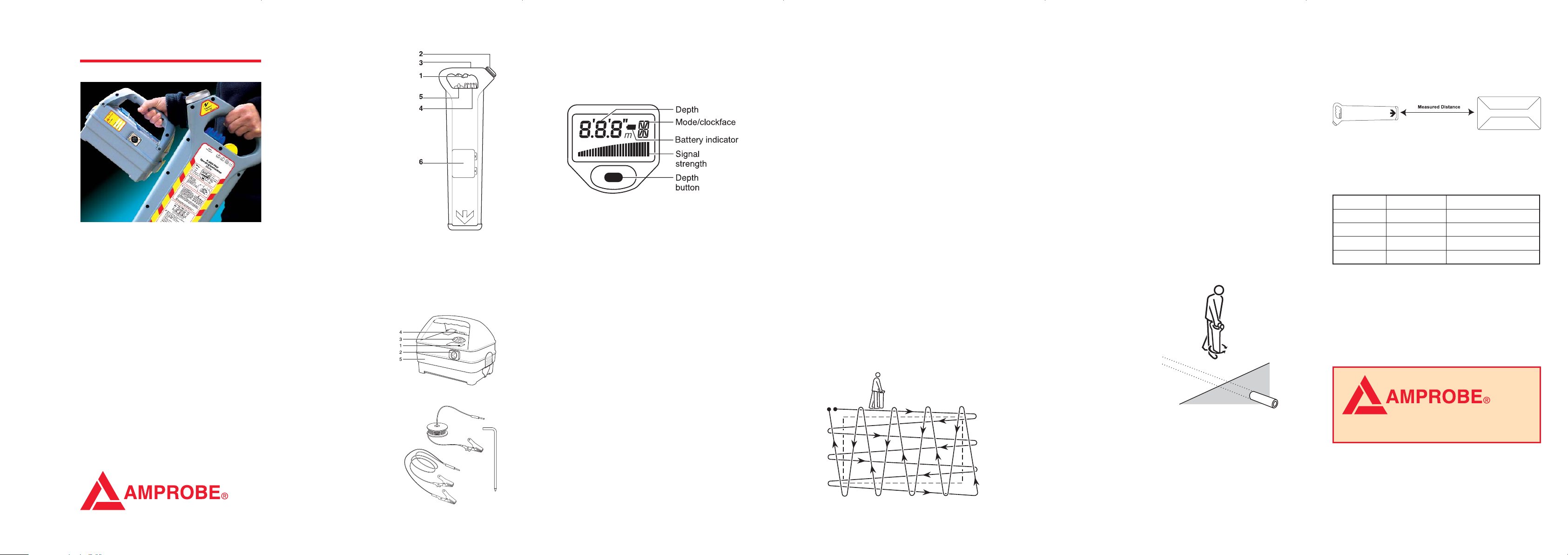
R-3000 PRO Locator features
1 On/Off
Press and hold to use R-3000 PRO
2 Loudspeaker
Detachable speaker for use
in noisy environments
3 LCD Display
4 Sensitivity Control
5 Function Switch
Selects locate mode
6 Battery compartment
To replace batteries, open the
access cover using a screwdriver
or coin. Use two LR20 or D type
alkaline batteries (or equivalent
NiMH rechargeable batteries)
WARNING
When using the R-3000 PRO in noisy environments, the
speaker can be detached and held closer to the ear.
To avoid excessive noise exposure it is advisable to
hold the speaker no closer than 15cm (6”) from the ear.
Prolonged use at this level should be avoided.
G-3000 PRO Signal
Generator features
1 On/Off button
Press to switch On and
Off. Press and hold to
reduce volume
2 Direct connection socket
3 Loudspeaker
4 Battery compartment
To replace batteries, open the
access cover using a screwdriver
or coin. Use four LR20 or D type
alkaline batteries (or equivalent
NiMH rechargeable batteries)
Trace the buried conductor keeping the R-3000 PRO vertical
and moving it steadily from side to side. Follow the line of the
buried conductor marking it with chalk or paint across the
area to be excavated.
Switch back to AvoidanceScan
™
mode to resume the sweep
of the area to be excavated.
Operation of Power and Radio modes
Power and Radio modes can be used independently of
AvoidanceScan™and it is recommended that this is done to
pinpoint services in very congested areas.
Regularly check your AT-3000 PRO, in all modes, over a
cable which gives a response you are familiar with.
Using Power mode
Select Power using the function switch.
Grip the handle.
Squeeze trigger and listen for bleep indicating the batteries
are OK. Replace both batteries if there is no bleep or if the
battery icon is flashing.
Rotate the Sensitivity Control fully clockwise for
maximum sensitivity but reduce if there is a blanket
signal across the site.
Define the area to be
excavated and carry
out a grid pattern sweep
as described in
AvoidanceScan
™
.
The presence of a
buried metallic pipe or
cable will be indicated
by a tone emitted from
the speaker. Keep the
blade of the R-3000
PROvertical and move
slowly backwards and
forwards over the cable or pipe, reducing the sensitivity for
a narrower response. Use the meter deflection to aid
pinpointing. Maximum meter deflection indicates the position
of the conductor.
Trace the conductor out of the area, marking the position
with chalk or paint.
ALWAYS DIG WITH CAUTION.
Using AvoidanceScan
™
Grip the handle.
Squeeze trigger and listen for bleep indicating the
batteries are OK. Replace both batteries if there is
no bleep or if the battery icon is flashing.
Turn Function Switch to A (AvoidanceScan
™
) to sweep the
area for conductors radiating Power, Radio or Genny signals.
In this mode the depth button will not be active and the
sensitivity control will only adjust the G-3000 PRO signal
level. (P and R will be set to maximum sensitivity).
Keep the sensitivity at maximum unless there is a blanket
G-3000 PRO signal, in which case turn down the
sensitivity until the blanket G-3000 PRO signal is reduced
to a usable level.
Note
Best results are obtained in the AvoidanceScan
™
mode when
the G-3000 PRO is set to pulse operation.
Sweep the area to be excavated with a steady and deliberate
motion. Hold the R-3000 PRO with the blade vertical and
with the bottom end just above the ground. Ensure the whole
area is covered by adopting a grid pattern.
Maximum meter and speaker response indicates the position
of a buried conductor.
If necessary switch to a dedicated mode (P,R or G-3000 PRO)
to pinpoint the conductor, adjusting the signal level control to
give a narrow locate band over the conductor. Rotate the
R-3000 PRO to give maximum response. The R-3000 PRO
is now at right angles to the conductor. (This can be less
precise in the power mode because of the nature of the
power signal).
5 Storage compartment
Holding connection cable,
Ground stake and ground cable
6 Pulse/Continuous switch
R-3000 PRO LCD features
The R-3000 LCD display provides visual representation of
the following parameters:
• Depth
• Battery indicator (flashing icon indicates
that batteries are low)
• Signal strength indicator
• Mode/clockface indicator
• Depth button
Operation of Power, Radio
and AvoidanceScan™modes
Regularly check your AT-3000 PRO, in all modes, over a
cable which gives a response you are familiar with.
AvoidanceScan
™
Use the AvoidanceScan™mode to undertake an initial sweep
of an area to be excavated. AvoidanceScan™will detect all
modes simultaneously.
Power signals:- radiated by loaded, unbalanced cables.
These signals are also found on other nearby conductors
that ‘re-radiate’ the power signal.
Radio signals:- originate from distant radio transmitters.
These penetrate the ground and are re-radiated by buried
conductors. However, they are not always present.
G-3000 PRO signals:- present on buried conductors that
have had a G-3000 PRO signal applied. There are various
ways of applying the G-3000 PRO signal (see Locating
with the AT-3000 PRO).
AT-3000 PRO
User Guide
This User Guide covers the use of the
underground wire tracer, the AT-3000 PRO.
The AT-3000 PRO consists of receiver
the R-3000 PRO and Generator, the
G-3000 PRO.
The R-3000 PRO provides four detection
modes, audio and visual indication and
depth measurment.
www.amprobe.com
2 3 4 5 12
90/UG063AMP
Page 2
Using Radio mode
Set the Function Switch to Radio.
Follow the same procedure as outlined in ‘Using the
Power mode’.
WARNING
Increased risk of property damage, death, or serious
injury may result if buried utilities, pipes, and cables are
not properly located before digging.
Make sure to read and follow all instructions and warnings
in the owner's guide when using the AT-3000 PRO.
The R-3000 PRO detects most buried cables and
conductors, BUT SOME CABLES AND CONDUCTORS
(EVEN LIVE ONES) DO NOT RADIATE SIGNALS, SO
THE R-3000 PRO WILL NOT DETECT THEM. Also, the
R-3000 PRO does not indicate whether a signal comes
from a single cable or conductor or from several cables
or conductors buried in close proximity to each other.
Even if using a AT-3000 PRO, ALWAYS DIG WITH
CAUTION.
Call your local support number (available from
www.radiodetection.com) for questions regarding
the proper use, maintenance, and repair of the
R-3000 PRO and Genny
3
.
Locating with the AT-3000 PRO
The G-3000 PRO is used to apply a tone to a buried
conductor. This signal can be traced using the R-3000 PRO
locator switched to the Genny mode.
Direct Connection
Direct connection is an
efficient form of signal
application and is
suitable for connection
to a valve, meter, junction
box or other access point.
WARNING
Connection to a power cable sheath should only be
undertaken by qualified personnel.
Method
Locate the target line as described previously.
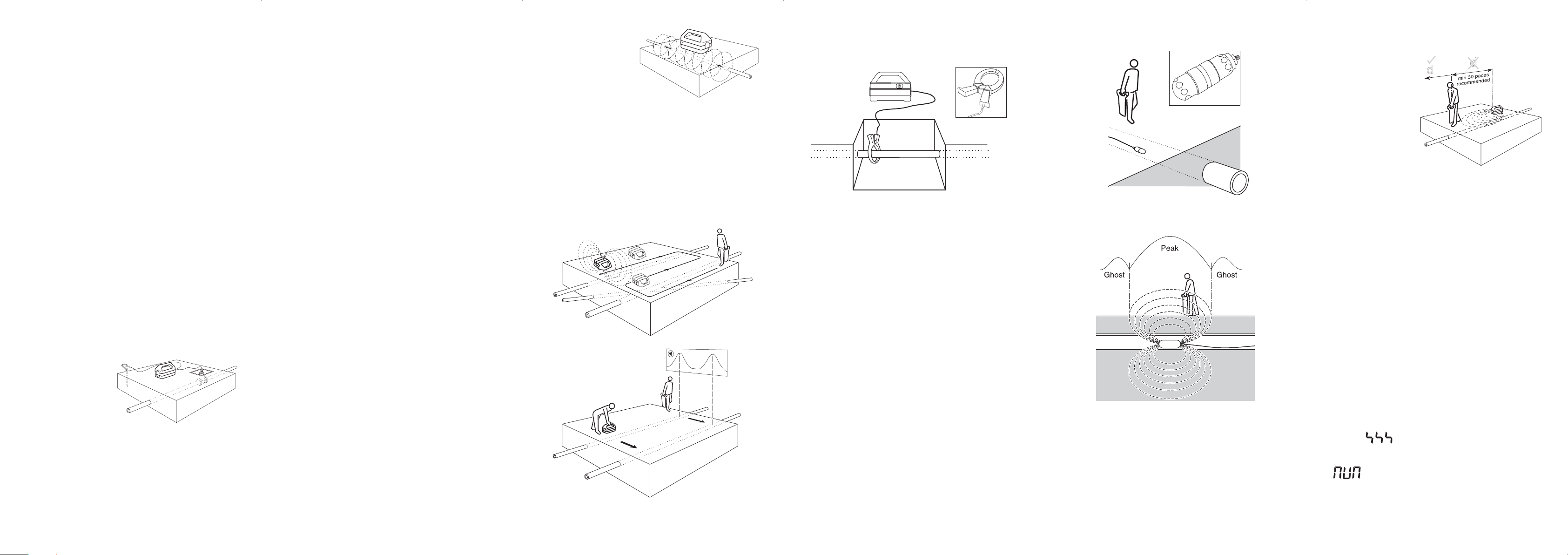
If using the G-3000
PRO in induction
ensure that the depth
measurement position
is at least 30 paces
from the G-3000
PRO. If using direct
connection or a signal
clamp, this distance
can be reduce to
approximately 5 paces.
Hold the R-3000 PRO still,
vertical and at right angles to the
buried line. Momentarily depress the depth button.
The display will show a moving clockface followed by the
depth measurement.
Taking Mouse depth measurements using the R-3000 PRO
Depth measurements are only possible when using the R-3000
PRO in the G-3000 PRO mode with a M-3000 transmitter,
identified with a central orange band.
Method
Locate the main Mouse signal as previously described. Hold
the R-3000 PRO vertical and in line with the Mouse. Press
and hold the depth button until ‘M’ appears on the display and
then release. A clockface will appear in the top right hand
corner of the display while the depth calculation is made.
The approximate depth to the Mouse will then be displayed.
Note
If the StrikeAlert
™
feature is enabled the alarm will activate at
approximately 1.2m when locating a sonde. If this is an
inconvenience, the StrikeAlert
™
feature can be disabled in the
Genny mode by pressing and holding the depth button for the
duration of the battery test bleep at switch on.
Error messages
Flashing indicates conductor out of range.
---
indicates depth attempted in radio which is not allowed.
not possible to indicate depth eg, high interference.
WARNING
Do not use the R-3000 PRO depth measurement to
decide if mechanical digging over a buried conductor
is appropriate.
Insert the Mouse approximately 1m/yd into the duct or drain
and adjust the R-3000 PRO sensitivity to receive the signal.
Smaller ghost signals appear before and behind the main
signal position. Locate all three peaks to be sure the largest
middle one is identified as the Mouse position.
Rotating the R-3000 PRO about it’s axis to obtain the largest
signal puts the blade of the R-3000 PRO in line with the
Mouse and is a good way of identifying the direction of the
duct or pipe.
Taking line depth measurements using
the AT-3000 PRO
For best accuracy use the G-3000 PRO in continuous
mode (it is possible to perform depth measurements with
the G-3000 PRO set to pulse mode but a slight reduction
in accuracy may be experienced).
Method
Decide if the G-3000 PRO is to be switched to pulse or
continuous operation. As a guide, depth measurements are
best done with a continuous signal. If battery power saving is
an issue, switch to pulse operation. A pulsing signal may also
be easier to detect as the signal gets weak towards the end
of the trace length. The pulse/continuous switch is located on
the underside of the G-3000 PRO.
Plug the connection lead into the G-3000 PRO connection
socket and attach the red lead to the target line. If necessary,
clean the connection point to ensure a good electrical
contact. If the jaws of the clip do not open far enough, and
the connection point is a ferrous material, use the magnet
that is on the clip to attach it.
Clip the ground lead to the earth stake which should be
placed in the ground 3 or 4 paces away from, and at right
angles to the target line.
Alternatively the ground lead may be clipped to the rim of a
valve box or manhole cover. Use the earth spool lead to
extend the earth connection if necessary.
Switch the G-3000 PRO on. After an initial warble, a good
connection is indicated by a drop in loudspeaker tone. If there
is no tone or it is a very slow bleep, replace the batteries.
Switch the R-3000 PRO to G-3000 PRO mode (or
AvoidanceScan
™
if conducting a general sweep) and begin
to trace the line from the point of application. Keep the blade
of the R-3000 PRO vertical and across the probable direction
of the line. Move slowly backwards and forwards over the
conductor, reducing the sensitivity for a narrower response.
Maximum audio and meter deflection will indicate the
position of the target line.
When directly over the line and with the sensitivity level
set for approximately
3
⁄4 deflection, rotate the R-3000 PRO
on it’s axis until a signal minimum is found. The blade is
now in line with the target line. Continue tracing the line as
outlined above.
Induction
Induction is a convenient and quick way of applying the
G-3000 PRO signal to a pipe or cable where limited access
does not permit direct connection or the use of a signal
clamp.
Using the optional Signal Clamp
The Signal Clamp applies a Genny signal safely to a pipe
or live cable up to 76mm (3 inches) diameter, without
interrupting the supply.
Method
Plug the Clamp into the G-3000 PRO Connection socket.
Place the Clamp around the pipe or cable ensuring the
jaws are closed. Switch the G-3000 PRO on. Open and close
the Clamp. If the jaws are closing correctly there will be
a change in tone as the jaws are closed.
An earth connection, from the G-3000 PRO, is not necessary
but efficient signal transfer is only achieved if the target
line is grounded at both ends. This is usually the case
with power cables.
The Signal clamp can be used with the G-3000 PRO set
to either pulse or continuous mode.
Using the optional Mouse Signal Transmitter
The Mouse is a small self-contained watertight transmitter
which can be detected by the R-3000 PRO when switched to
the G-3000 PRO mode.
Method
Unscrew the housing and insert the single LR6 or AA type
alkaline battery in the orientation shown by the diagram
in the battery compartment.
Note
Placing the battery in the incorrect orientation will not harm
the Mouse and is a good method of storing the battery
when not in use.
Place the Mouse on the ground, set the R-3000 PRO to
G-3000 PRO mode and, whilst holding the R-3000 PRO
in line with the Mouse, check that the signal is being received.
Set the G-3000 PRO
to pulse or continuous
mode. Place the
G-3000 PRO over
the assumed position
of the conductor
and in the orientation shown.
Start tracing the target line at
least five paces from the G-3000 PRO
with the R-3000 PRO set in the G-3000 PRO mode. Working
too close to the G-3000 PRO may give false readings as
the R-3000 PRO will detect radiated signals directly from the
G-3000 PRO rather than the target line.
Active search using Induction
Placing the G-3000 PRO on it’s side swamps an area with
G-3000 PRO signal. Note that signal is not transmitted
directly below the G-3000 PRO in this orientation, so repeat
the exercise with the G-3000 PRO moved to the side by at
least one metre.
Alternatively, use a two
man technique to search
an area for buried
utilities as shown.
76 8 9 10 11
 Loading...