

Page 1

Users Manual
AT-1000
Advanced Wire
Tracer
Page 2

AT-1000
Advanced Wire Tracer
Users Manual
AT1000_Rev001
© 2008 Amprobe Test Tools.
All rights reserved.
English
Page 3

Limited Warranty and Limitation of Liability
Your Amprobe prod uct will be free from defect s in mate rial and w orkma nship for 2 years
from the d ate of purchase. This warrant y does n ot cover f uses , disp osable batteries or
damage from accident , neglect, misus e, alteration, contaminatio n, or abnormal conditi ons
of opera tion or handling. Rese llers a re not au thorize d to extend any other war ranty on
Amprobe’s be half. To obtai n service dur ing the wa rrant y perio d, return the produc t with
proof of p urchase to an authorize d Ampro be Test Tools Service Cen ter or to an Ampro be
dealer o r distributo r. See Repair Sec tion for d etail s. THIS WARR ANT Y IS YOUR ONLY REMEDY.
ALL OTHER WARR ANTIES - WHE THER E XPRESS, IM PLIED O R STAUTORY - INCLUDING
IMPLI ED WARR ANTIES OF FI TNESS FOR A PARTICUL AR PURPOSE O R MERCH ANTABI LIT Y, ARE
HEREBY DI SCL AIMED. MANU FACTURER SHALL NOT BE LIABLE FOR ANY SPECIAL, IN DIREC T,
INCID ENTAL OR CO NSEQU ENTI AL DAMAG ES OR LOSSES, ARISIN G FROM AN Y CAUS E OR
TH EOR Y. Since some states or countrie s do not all ow the exclusion or limit ation of a n implie d
warrant y or of incidental or con sequ ential d amage s, thi s limita tion of liabilit y may not apply
to you.
Repair
All test tools returne d for war ranty o r non- warran ty rep air or for calibration sh ould be
accomp anied by the following: yo ur name , company’s nam e, address , telep hone nu mber,
and proof of purchase. Additio nally, ple ase include a brief descript ion of the p roble m or
the ser vice re ques ted an d include the test lead s with th e meter. Non-wa rrant y repair or
replac ement c harge s shoul d be remi tted i n the form of a check, a mone y order, credit ca rd
with expiration date, or a purcha se order made p ayable to Ampro be® Test Tools.
In-Warranty R epair s and Replacement – All Countr ies
Please read the warrant y statemen t and che ck your battery bef ore requesting repair. During
the warra nty period any defec tive te st too l can be re turne d to your Amprob e® Test Tools
distributor f or an exchange fo r the same or like produc t. Plea se che ck the “Where to Buy”
section on w ww.amprob e.com fo r a list of d istri butor s near you. Additionally, in the United
States a nd Canada In-Warranty repair and re placement units can also be s ent to a Am probe®
Test Tools Service Center (see ad dress below).
Non-Warrant y Repairs and Replacement – US and Can ada
Non- warranty repairs in th e Unite d State s and Canada should be sent to a Amprobe ® Test
Tools Ser vice Ce nter. Call A mprobe® Test Tool s or inquire at your point of p urcha se for
curren t repair a nd repl aceme nt rates.
In USA In Canada
Amprobe Test Tools Amprobe Test Tools
Everett, WA 98203 Mississauga, ON L4Z 1X9
Tel: 877-AMPROBE (267-7623) Tel: 905- 890-7600
Non-Warrant y Repairs and Replacement – Eu rope
Europea n non- warran ty uni ts can b e repla ced by you r Amprobe® Tes t Tools distributor for a
nominal charge. Please check the “Wh ere to Buy” sec tion on w ww. ampro be.com for a list of
distributor s near yo u.
2
Page 4
R1000 Receiver
X1000 Transmitter
3
Page 5

CONTENTS
Symbols ....................................................................................................................................................
5
Introduction .............................................................................................................................................
5
Safety Precautions and Warnings ..........................................................................................................
5
Unpacking and inspection ......................................................................................................................
6
Component Description ..........................................................................................................................
6
R1000 Receiver ...................................................................................................................................
6
X1000 Transmitter ..............................................................................................................................
6
Replacing Batteries: R1000 and X1000 ..................................................................................................
7
Operation ................................................................................................................................................
7
Tracing Energized Wires .........................................................................................................................
7
Locating Opens ........................................................................................................................................
8
Locating Shorts ........................................................................................................................................
8
Fuse Replacement ...................................................................................................................................
8
Specifications ...........................................................................................................................................
9
Advanced Wire Tracer
AT-1000
4
Page 6

SYMBOLS
Battery
Double insulated
Direct Current
Alternating Current
Conforms to relevant Australian
standards.
Do not dispose of this product as
unsorted municipal waste.
Application around and removal
from hazardous live conductors
is permitted
INTRODUCTION
AMPROBE is dedicated to designing, manufacturing and marketing high quality, reliable
instruments for the skilled professional. AMPROBE has a history of providing safe, reliable
equipment to trace energized wires, circuit breakers, tracing deenergized wires, and locating
opens. The AT-1000 Advanced Tracing System combines these features in one versatile tool and is
effective in solving most tracing problems.
The AT-1000 is a troubleshooting tool. An experienced troubleshooter will understand how
the system to be traced works under normal conditions, and be familiar with the types of
malfunctions that can exists. A thorough understanding of “Ohms Law” is helpful. It is a
good idea to test the circuit for parameters such as Volts, Ohms, and Current to determine
whether the circuit is “shorted”, “semi-shorted”, or “open”, before attempting to trace. The
characteristics of these malfunctions will designate which components, and tracing method, will
be most effective in locating these malfunctions.
A thorough understanding of the operation and function of each of the AT-1000 components is
essential. Overall, this knowledge could mean the difference between spending several minutes
or several hours on a job. Pay special attention to the “Safety Precautions and Warnings”.
Experiment under known conditions. You will gain the confidence to use it on a daily basis and
solve problems which were previously unsolvable.
SAFETY PRECAUTIONS AND WARNINGS
Read this manual in its entirety before proceeding with any testing.1.
Refer to the manual
Dangerous Voltage
Earth Ground
Audible tone
Complies with EU directives
Underwriters Laboratories.
5
Page 7

This equipment should only be used by trained professionals who are familiar with electrical 2.
hazards.
Wear lineman gloves, safety glasses, and protective clothing at all times.3.
Do not attempt to replace or remove the battery in the X1000 Transmitter until X1000 is 4.
removed from the circuit and the cord set test leads are removed from the X1000 transmitter.
Always inspect the components and accessories for damage and proper operation BEFORE 5.
using. Replace any damaged components.
Before connecting the X1000 Transmitter to a circuit, verify that the voltage, at the intended 6.
point of contact, does not exceed 300VAC/DC.
Store the components in the case when not in use.7.
Remove the battery from the R1000 Receiver and X1000 Transmitter if the components will 8.
not be in use for a long period of time.
Before proceeding with any testing, confirm the X1000 is functioning correctly by switching 9.
the X1000 to the “ON” position. The Battery Indicator should flash. If the Battery Indicator
remains “OFF”, replace the battery.
Connections to the test circuit should be made after insertion of test leads into X1000.10.
UNPACKING AND INSPECTION
AT-1000 (US version) AT-1000E (Europe version)
1 x R1000 Receiver 1 x R1000 Receiver
1 x X1000 Transmitter 1 x X1000 Transmitter
1 x C2901 Cordset 2 x Test probes (in set EU-200)
1 x C2902 Cordset 2 x Crocodile clips (in set EU-200)
1 x AD-1 Adapter 2 x Test leads (in set EU-200)
1x Instruction Manual 1 x. Instruction Manual
1x Soft Carrying case 1 x Hard carrying case
2 x 9V Battery 2 x 9V Battery
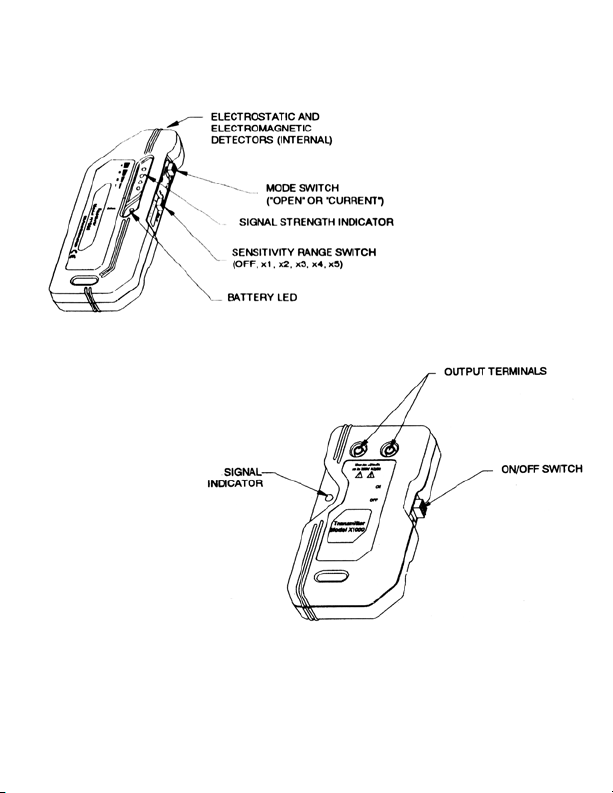
COMPONENT DESCRIPTION
R1000 Receiver
The R1000 contains two built-in detectors that are tuned to pick-up the 17kHz signal generated
by the X1000. The detector is selected by the MODE Switch. The “OPEN” position selects the
electrostatic (voltage potential) detector. The “CURRENT” position selects the electromagnetic
(current) detector. The selection of detector depends on the condition of the circuit to be traced.
The electromagnetic detector is set in one direction within the R1000 housing. The manner
in which the receiver is held, and the direction in which the detector is pointed, will vary the
amount of signal that is displayed and give the user an indication of the direction of the wire
being traced. This is particularly evident when the R1000 is in the “CURRENT” MODE. Pointing
the receiver perpendicular to the wire, so that the front label faces the direction of the wire, will
yield the maximum signal displayed.
6
Page 8

The R1000 is designed to display the signal strength visually with a series of four LED’s, and
audibly by emitting a pulsed tone. The R1000 is turned “ON” and “OFF”, as well as varying the
amount of signal strength that is displayed, by the Sensitivity Range Switch (OFF, X1, X2, X3, X4,
X5). The Battery LED illuminates when the R1000 is turned ON. The distance the R1000 is held
from the wire carrying the signal will also vary the signal strength that is displayed. The receiver
can typically detect a signal approximately 1-3 feet away from the wire carrying the signal.
Always try to keep the sensitivity low enough, or high enough, to maintain a maximum of 3
LED’s on the indicator so the wire that is carrying the maximum signal is easily identified.
The user must vary the sensitivity to what is considered an acceptable, usable level (usually
3 LED’s), while holding the receiver in the proper direction, to locate the conductor that is
carrying the signal and to identify its direction.
X1000 Transmitter
Warning
X1000 – Do not connect to live circuits above 300VAC/DC!
The X1000 Transmitter enables tracing of energized circuits up to 300VAC/DC as well as tracing
deenergized lines.
When connected to a closed or energized circuit that allows current to flow, the X1000 will
turn on and off and cause a 17kHz current fluctuation that can be detected, by the R1000 in
the “CURRENT” mode, along the circuit path. The signal will flow to the lowest impedance in
the circuit. Usually, the signal is more evident and detected on the conductors going back to
the source (transformer). To increase the signal current travelling to the source (transformer),
disconnect any know loads on that circuit.
When connected to an open circuit, the X1000 will inject a 17kHz voltage fluctuation that can
be detected, by the R1000 in the “OPEN” mode, along the circuit path to the end of that circuit.
Proper operation of the X1000 Transmitter is confirmed when the R1000 received indicates a
pulsed signal.
REPLACING BATTERIES: R1000 AND X1000 (see Fig. 1)
Warning
Do not attempt to replace or remove the battery in the X1000 Transmitter until X1000 is
removed from the circuit and the cord set test leads are removed from the X1000 Transmitter.
The patented battery compartment, on the back of the R1000 and X1000, allows you to replace
the battery quickly and easily. Two holes on the bottom of the compartment accept the round
terminals of a 9 volt battery. The compartment is designed to accept the battery in only one
orientation, so if the door doesn’t close, turn the battery 180° and try again.
OPERATION
Warning
Make sure the line voltage DOES NOT EXCEED the range of the X1000: 300VAC/DC max.
Using either the C2901 Pigtail Cords Set for 120V receptacles (see Fig. 2), or the C2902 1.
Alligator-Clip Banana Plug Cord Set (see Fig. 3), connect the X1000 Transmitter to the circuit
7
Page 9

(see Fig. 4). When using the C2902, always connect to ground first and disconnect from
ground last.
Switch the R1000 Receiver “ON” by sliding the Sensitivity Range Switch” to position 3 and set 2.
the R1000 Mode Switch to “CURRENT MODE”.
Verify that the X1000 Transmitter is generating a current signal by placing the R1000 tip 3.
against one of the cord set leads.
Go to the panel and move the Receiver up and down, and in front of, each circuit breaker to 4.
determine which one has the strongest signal. Remember to keep the receiver perpendicular
to the breakers. Reduce the R1000 sensitivity with the “Sensitivity Range Switch” if the signal
strength goes above 4 LED’s. Leave it in this position until you come across another breaker
with a stronger signal. The strongest signal will determine the proper breaker.
If two or more breakers produce the same signal strength indication, reduce the sensitivity or 5.
pull back the R1000 slightly from the breakers until detecting the right one.
TRACING ENERGIZED WIRES
Warning
Make sure the line voltage does not exceed the range of the X1000 Transmitter: 300VAC/DC
max.
The X1000 Transmitter produces opposing signals on each output terminal. When the conductors
that are connected to these terminals come within close proximity of each other, the signal
strength is attenuated (see Fig. 5).
This can make tracing conductors more difficult, if not impossible. In most cases you can solve
this problem by using the C2902 cord set and connecting one output terminal to a different
signal return path. Use something other than the return (neutral) running adjacent to the
conductor you are trying to trace, like a water pipe or a ground rod. The AD-1 adapter enables
access to the hot conductor in 120VAC receptacles (see Fig. 6).
Connect the X1000 Transmitter as in Fig. 6 and turn the unit “ON”.1.
Set the R1000 Mode Switch to the “CURRENT “ MODE.2.
Switch the R1000 Receiver “ON” by sliding the “Sensitivity Range Switch” set to position 5.3.
Verify that the X1000 Transmitter is generating a current signal by placing the tip against one 4.
of the cord set leads.
Move the R1000 Receiver along the conductor path, perpendicular to the conductor, and 5.
adjust the “Sensitivity Range” as needed to maintain approximately 3-4 LED’s of signal
strength.
Proceed to trace the wire by moving the R1000 left to right over the path of the wire so that 6.
you can see the rise and fall of the signal level (see Fig. 7). The strongest signal confirms the
path of the wire. If the signal drops off, the wire may have taken a turn in another direction.
Before attempting to adjust the sensitivity, back track and try tracing from another angle, if
possible. If the signal becomes too strong, adjust the sensitivity as necessary.
8
Page 10

LOCATING OPENS
“Opens” are deenergized conductors that are not connected to a source or a load, and therefore
do not pass current. First verify that the conductor is deenergized, using a voltmeter, then verify
that it is open, with respect to ground and/or adjacent conductors, using an Ohmmeter.
Using the C2902 Cord Set, connect the X1000 Transmitter to the open conductor and a 1.
separate ground as shown in Fig. 8. Use the AD-1 if applicable.
Where possible, ground any other conductors sharing the same path as the open wire to 2.
reduce capacitive coupling, or “signal bleed-off” onto those conductors.
Switch the R1000 Receiver to the “OPEN” mode and turn the receiver “ON” by sliding the 3.
“Sensitivity Range Switch” and set it to position 5.
Verify that the X1000 Transmitter is generating a signal by placing the R1000 tip against one 4.
of the cord set leads.
Proceed to trace the wire by moving the R1000 left to right over the path of the wire so 5.
that you can see the rise and fall of the signal level (see Fig. 7). Adjust the “Sensitivity Range
Switch” to display 3 LED’s of signal strength. The strongest signal confirms the path of the
wire. If the signal drops off, the wire may have taken a turn in another direction, or may be
open at this point. Before attempting to adjust the sensitivity, back track and try tracing from
another angle, if possible. Pinpoint the location of the open (where the signal drops off) by
reducing the sensitivity while decreasing the distance between the R1000 and the conductor.
If possible, repeat the process starting from the other end of the wire to verify the location 6.
of the open.
LOCATING SHORTS
Using the C2902 Cord Set, connect the X1000 Transmitter to the shorted conductor and a 1.
separate ground as shown in Fig. 9. Use the AD-1 adapter if tracing a conductor connected to
a receptacle.
Switch the R1000 Receiver to the “CURRENT” mode and turn the receiver “ON” by sliding the 2.
“Sensitivity Range Switch” and set it to position 5
Verify that the X1000 Transmitter is generating a signal by placing the R1000 tip against one 3.
of the cord set leads.
Proceed to trace the wire by moving the R1000 left to right over the path of the wire so 4.
that you can see the rise and fall of the signal level (see Fig. 7). Adjust the “Sensitivity Range
Switch” to display 3 LED’s of signal strength. The strongest signal confirms the path of the
wire. If the signal drops off, the wire may have taken a turn in another direction, or may be
shorted at this point. Before attempting to adjust the sensitivity, back track and try tracing
from another angle, if possible. Pinpoint the location of the short (where the signal drops
off) by reducing the sensitivity while decreasing the distance between the R1000 and the
conductor.
If possible, repeat the process starting from the other end of the wire to verify the location 5.
of the short.
9
Page 11

Fig. 1: Battery Replacement
Fig. 2a: C2901 Cordset
Fig. 2b: C2902 Cordset
Fig. 3: EU-200 Cordset
10
Page 12

Fig. 4: Locating Breakers
Fig. 5: Signal Attenuation
11
Page 13

Fig. 6: Tracing Conductors
Fig. 7: Tracing Wires
12
Page 14

Fig. 8: Tracing Opens
Fig. 9: Locating Shorts
13
Page 15

Fig. 10a: Back View Fig. 10b: X1000 with Front
Fig. 10: Fuse Replacement
Cover Removed
14
Page 16

Visit www.Amprobe.com for
Catalog•
Application notes•
Product specifications•
User manuals•
Please Recycle
 Loading...