

Page 1

99 Washington Street
Melrose, MA 02176
Phone 781-665-1400
Toll Free 1-800-517-8431
Visit us at www.TestEquipmentDepot.com
HD160C
Heavy-Duty True-rms Digital Multimeter
User Manual
English
Page 2

HD160C
OFF
2 A
mA
A
V
V
Hz
F
C
REL
MIN MAX
AVG
RANGEHOLD
A
HD160C
V
A
Temp
COM
2A MAX
FUSED
MAX
1500V
1000V
IV
CAT
1000 V
Hz
1
2
3
4
5
6
7
8
9
10
11
12
13
# Description
1 COM Input - common or low input for all measurements
2 Current and Capacitance Input
3 Function/Range Selector Switch
4 MIN MAX AVG Button
5 RELative Button
6 Low Battery Indicator
7 Hold Indicator
8 4-Digit LCD with measurement indicators
9 Data HOLD Button
10 RANGE Lock Button
11 AC DC Selection Button for Current Ranges
12 Backlight Button
13 Temperature, Volts, Ohms, and Frequency Input
Page 3

HD160C
Contents
Symbols .........................................................................................................................................2
Introduction ..................................................................................................................................2
Warnings and Precautions ...........................................................................................................2
Unpacking and Contents .............................................................................................................3
Display Symbols and Audible Symbols ........................................................................................4
Overload Condition ......................................................................................................................4
Incorrect Input Warning ..............................................................................................................4
Dangerous Voltage Warning .......................................................................................................4
Audible Feedback .........................................................................................................................4
Analog Bargraph ..........................................................................................................................5
Disable Beeper and Auto-Power Off ..........................................................................................5
Measuring Procedures .................................................................................................................5
Measuring DC Voltage (See Figure 1) .........................................................................................5
Measuring AC Voltage - True rms (See Figure 2) ........................................................................6
True rms AC Measurements .........................................................................................................6
Measuring DC Current (See Figure 3) .........................................................................................7
Measuring AC Current - True rms (See Figure 4) ........................................................................7
Continuity Test (See Figure 5) ......................................................................................................8
Resistance Measurement (See Figure 6) .....................................................................................8
Measuring Capacitance (See Figure 7) ........................................................................................9
Measuring Frequency (See Figure 8) ...........................................................................................9
Measuring Temperature (See Figure 9) ......................................................................................9
Button Functions ........................................................................................................................10
RANGE.......................................................................................................................................10
HOLD .........................................................................................................................................10
REL (Relative Measurements) .................................................................................................10
MIN MAX AVG ..........................................................................................................................11
Auto-Power Off ..........................................................................................................................11
Safety Test Leads ........................................................................................................................11
Specifications ..............................................................................................................................12
General Specifications..............................................................................................................12
Electrical Specifications ............................................................................................................12
DC Volts ............................................................................................................................12
AC Volts True rms ............................................................................................................13
DC Current .......................................................................................................................13
AC Current True rms ........................................................................................................ 13
Resistance .........................................................................................................................13
Continuity Test .................................................................................................................13
Capacitance ...................................................................................................................... 13
Temperature ....................................................................................................................13
Frequency ......................................................................................................................... 13
Optional Accessories ................................................................................................................13
Maintenance and Repair ...........................................................................................................14
Battery/Fuse Replacement (Figure 10) ......................................................................................14
Repair Information .....................................................................................................................15
Test Equipment Depot - 800.517.8431 - 99 Washington Street Melrose, MA 02176
FAX 781.665.0780 - TestEquipmentDepot.com
Heavy-Duty True-rms Digital Multimeter
Page 4

Symbols
Battery
B
Double insulated
Direct Current
Alternating Current
Fuse
Conforms to relevant Australian
standards.
Do not dispose of this product as unsorted municipal waste. Contact
Amprobe or a qualified recycler for disposal.
Refer to the manual
Dangerous Voltage
Earth Ground
Audible tone
Complies with EU directives
Canadian Standards Association.
®
[Note: Canadian and US.]
Introduction
The Amprobe digital multimeter HD160C is a heavy-duty 4-digit, autoranging, AC-coupled
True rms measuring instrument that measures voltage, current, resistance, continuity, as
well as capacitance, frequency and temperature. It also offers Range Lock, Data Hold,
Relative Measurement, Auto Min Max Measurement, a bright backlight, and Auto Power
Off to save battery life. The instrument is completely o-ring sealed to pass strict IP-67
ratings for moisture and dust proof. The HD160C also has internal components shock mounted for drop proof capability. The HD160C meets the highest safety rating of CAT IV
1000 V (1500V DC max).
Warnings and Precautions
This instrument is EN61010-1 certified for Cat IV, 1000 V ac/1500 V dc and lower
installations. Based on EN61010-1 transient requirements, this product should
only be used in installations where transients do not exceed 12,000 volts (a 1.2
µS/50 µS pulse).
• All inputs are protected against overload conditions up to the limits of each
function's stated input protection (see specifications). Never exceed these
limits or the ratings marked on the instrument itself.
• Exercise extreme caution when: measuring voltage >20 V, current >10 mA, ac
power line with inductive loads, ac power line during electrical storms. High
voltages can be lethal and high voltage transients may occur at any time.
• Operator injury or damage to the multimeter may occur during current
measurements if the fuse blows in a circuit with open circuit voltage 1000 V
ac/1500 V dc.
2
Page 5

• Always inspect your DMM, test leads and accessories for signs of damage or
abnormality before use. If an abnormal condition exists (broken or damaged
test leads, cracked case, display not reading, etc.), do not use. All internal
battery and fuse covers are integral to the EN61010-1 Cat IV safety rating and
must be in place to avoid potential shock hazards.
• When testing for voltage or current, make sure these ranges function correctly.
Take a reading of a known voltage or current first.
• Never ground yourself when taking measurements. Do not touch exposed
metal pipes, outlets, fixtures, etc., which might be at ground potential. Keep
your body isolated from ground and never touch exposed wiring, connections,
test probe tips, or any live circuit conductors. Do not use the Flex-Strap to
attach the meter to your body.
• Always measure current in series with the load – NEVER connect the
multimeter ACROSS a voltage source. Check fuse first.
• Never replace a fuse with one of a different rating.
• Do not operate instrument in an explosive atmosphere (flammable gases,
fumes, vapor, dust.)
• Do not use this or any piece of test equipment without proper training
• CRT SERVICE SAFETY REMINDER: A potential danger exists when measuring
voltages in the horizontal output and damper stages of CRT equipment. (High
voltage transients greater than 8000 V). Refer to your CRT service manual for
proper servicing instructions.
Unpacking and Contents
Your shipping carton should include the HD160C multimeter, a holster with Magna-Grip,
one test lead set with alligator clips(one black, one red), one temperature adaptor, one
Type K thermocouple probe, one 9 V battery (installed), a hex wrench (held inside holster)
and this manual. If any of the items are damaged or missing, immediately return the
complete package to the place of purchase for an exchange. The holster/tilt stand provides
additional protection of the meter from accidental falls and provides greater ease of
use. Both test lead probes can be attached to the holster for storage. One probe can be
attached for measurement, holding the meter with probe in one hand and the second
probe in the other hand.
3
Page 6

Display Symbols and Audible Symbols
Dangerous voltage warning (also double beep tone). Indicates input
voltages higher than 30 V ac or 60 V dc.
Low-battery voltage
B
- Negative polarity indicator
Overload Condition
Input Overload (highest range in autoranging) is indicated by “OL or -OL” and a
continuous tone. Remove test leads from the measurement setup as the input is beyond
the range of the meter.
Display Overload (input exceeds the selected range while range is locked) is also indicated
by “OL or -OL”. Select the next higher range until a value is displayed, or return to
autoranging. If overload still exists in the highest range, remove test leads from the
measurement setup as input is beyond the range of the meter.
Note: In both instances, overload indication is normal in the ohms and continuity ranges
(no sound) when the leads are not connected to anything or when the measured value is
higher than the selected resistance range.
Incorrect Input Warning
The meter displays a function error code “Err” when a test lead is placed in the A input
jack and the Selector switch is not set to a current or capacitance range. (If the meter is
connected to a voltage source with leads connected for current, very high current could
result). All current ranges are protected with a fast acting fuse.
Dangerous Voltage Warning
Displayed voltage warning and double-beep warning when input voltages are greater than
30 V ac/60 V dc, .
Audible Feedback
The meter emits a single beep when a parameter is changed, a “valid” front panel button
is pushed, or Auto Min Max values are updated. A double beep indicates a dangerous input
voltage (>30 V ac or 60 V dc).
The meter emits a continuous tone in the case of input overload, for continuity
measurement when resistance is <40Ω, and for current measurements, when the A input is
used and the current
exceeds 2 A.
4
Page 7

Analog Bargraph
The 41 segment analog bargraph indicates the percentage of the range the displayed
measurement relates to. The zero segment is lit when the instrument is turned on. Each
segment after that equals 2.5 % of range. The 400 mA, 40 MΩ, and Capacitance ranges are
limited to 16 segments.
Example: a 500 mV input in the 1 V range (50 %) is represented by 21 segments (50).
400mA (of a theoretical 1000 mA range) = 16 segments (40 %).
Disable Beeper and Auto-Power Off
You can disable the beeper and Auto Power Off by pressing and holding the REL button
while turning the meter ON.
Measuring Procedures
• Turn instrument on by turning function/range switch away from OFF and
selecting the parameter you want to measure.
• This instrument is autoranging on all ranges. It automatically selects the range
that gives the best resolution for the measured value. A range can be locked
through menu selection (see Button Functions, later in this manual). You
can tell which range you are in by the position of the decimal point and the
measurement unit displayed.
• When connecting or disconnecting test leads to a circuit, always turn off power
to device or circuit being tested and discharge all capacitors.
• Strictly observe the max input limits.
• Do not change functions while test leads are connected to circuit.
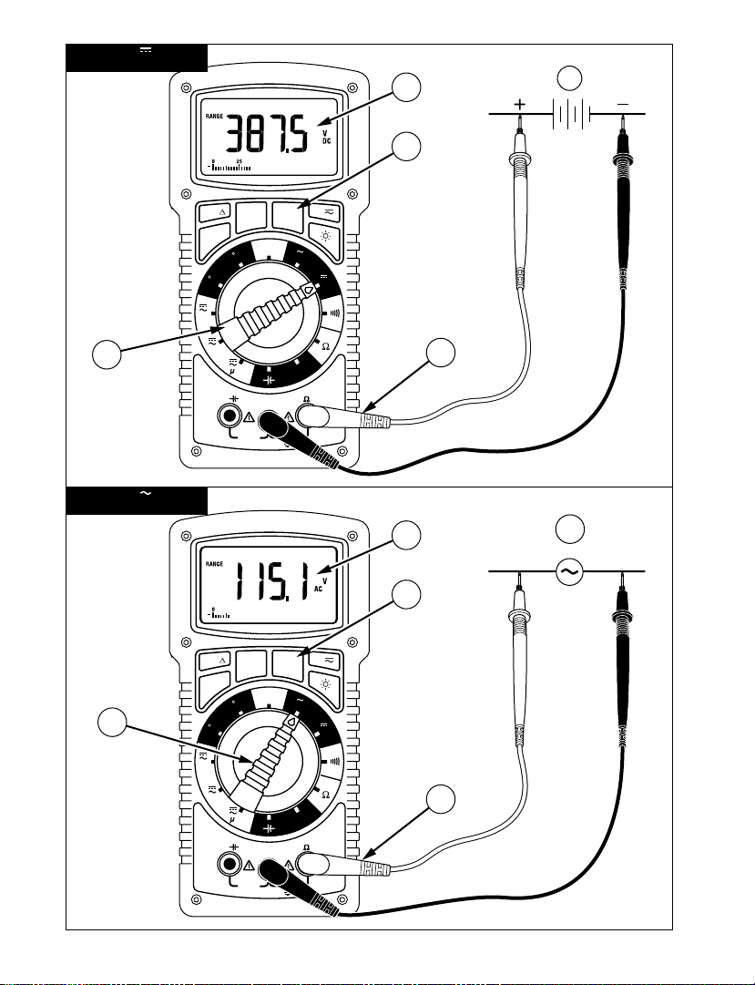
Measuring DC Voltage (See Figure 1)
1. Set the Function Switch to .
2. If
RANGE is displayed, press the RANGE button to enable auto ranging.
3. Connect the test leads: Red to
4. Connect the test leads to the circuit test points.
5. Read the display, and, if necessary, correct any overload (OL) conditions.
Temp VΩHz, Black to COM
Test Equipment Depot - 800.517.8431 - 99 Washington Street Melrose, MA 02176
FAX 781.665.0780 - TestEquipmentDepot.com
Page 8

Measuring AC Voltage - True rms (See Figure 2)
5.0
4.0
3.0
2.5
1.0
2%
0%
5%
4%
3%
100%806040200
Wave form,Crest Factor
Additional correction from 1.5 to 5.0
Input RMS, Percentage of Full-Scale
1. Set the Function Switch to .
2. If
RANGE is displayed, press the RANGE button to enable auto ranging.
3. Connect the test leads: Red to
4. Connect the test leads to the circuit test points.
5. Read the display, and, if necessary, correct any overload (OL) conditions.
Temp VΩHz, Black to COM
True rms AC Measurements
Model HD160C is an ac-coupled True rms measuring meter. It measures the True rms value
of distorted AC voltage or current signals. The Crest Factor handling capability is shown in
Table 1. The Crest Factor is the Peak Voltage divided by the rms voltage.
Table 1 - Crest Factor Handling Capability
Note: To accurately measure a DC voltage with an AC component, measure the AC
component first with selector switch set to . Note the measurement and range used.
Switch to , activate Range Lock (see Button Functions later in this manual) and select a
range equal to or higher then the range used previously. Note the measurement. The
result is the measured AC Voltage on top of the measured DC component. (Max input is
1500 V dc or 1000 V ac).
6
Page 9

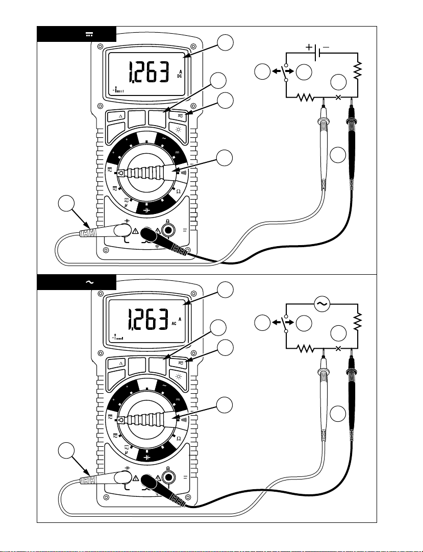
Measuring DC Current (See Figure 3)
1. Set the Function Switch to a current function, μA, mA, or 2A.
2. If AC is displayed, press the
3. If the 2A function is not selected and
to enable auto ranging.
4. Connect the test leads: Red to
5. Turn off power to the circuit being measured.
6. Open the circuit (-X-) in which current is to be measured (voltage between this
point and ground must not exceed 1500 V dc).
7. Securely connect test leads in series with the load.
8. Turn on power to the circuit being measured.
9. Read the display, and, if necessary, correct any overload (OL or -OL) conditions.
A button to turn on DC.
RANGE is displayed, press the RANGE button
A, Black to COM.
Measuring AC Current - True rms (See Figure 4)
1. Set the Function Switch to a current function, μA, mA, or 2A.
2. If DC is displayed, press the
3. If the 2A function is not selected and
to enable auto ranging.
4. Connect the test leads: Red to
5. Turn off power to the circuit being measured.
6. Open the circuit (-X-) in which current is to be measured (voltage between this
point and ground must not exceed 1000 V ac).
7. Securely connect test leads in series with the load.
8. Turn on power to the circuit being measured.
9. Read the display, and, if necessary, correct any overload (OL) conditions.
A button to turn on AC.
RANGE is displayed, press the RANGE button
A, Black to COM.
7
Page 10

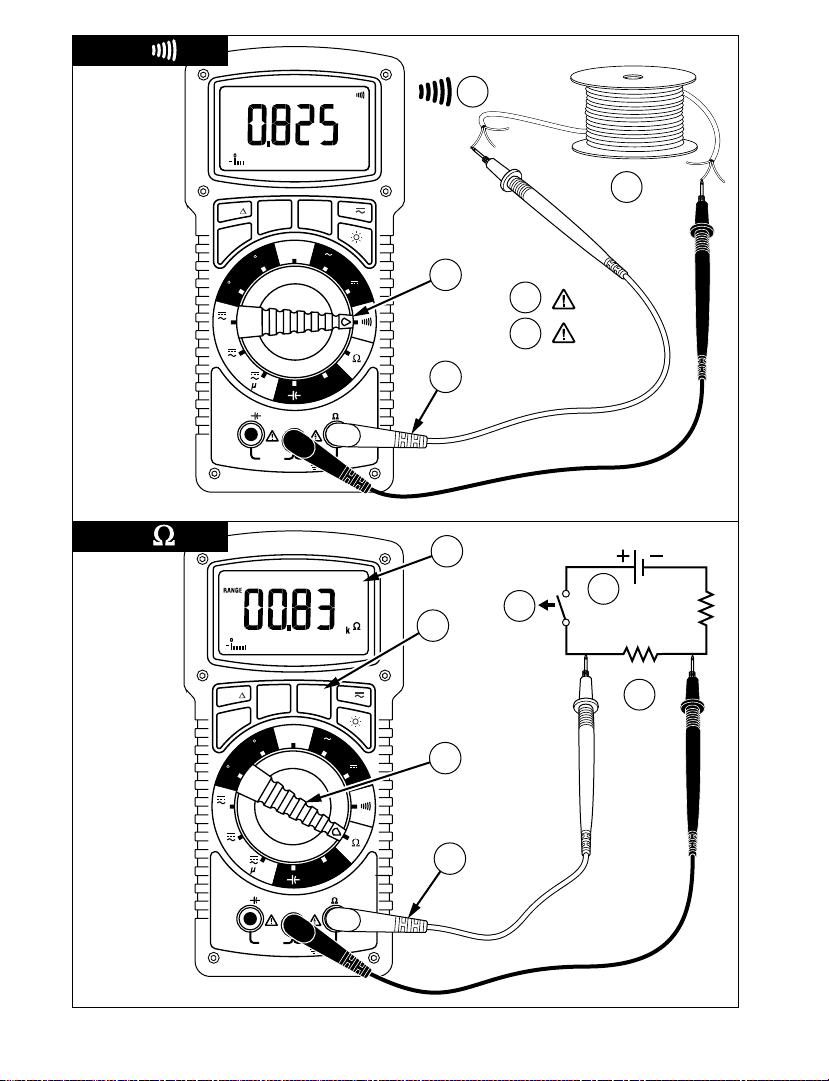
Continuity Test (See Figure 5)
1. Set the Function Switch to .
2. Connect the test leads: Red to
3. Turn off power to the circuit being measured.
4. Discharge any capacitors that may influence the reading.
5. Connect the test leads across the resistance.
6. Listen for the tone that indicates continuity (< 40
When measuring continuity the meter emits a continuous tone when the resistance value
falls below 40Ω.
Temp VΩHz, Black to COM.
Ω).
Resistance Measurement (See Figure 6)
1. Set the Function Switch to Ω.
2. If
RANGE is displayed, press the RANGE button to enable auto ranging.
3. Connect the test leads. Red to
4. Turn off power to the circuit being measured. Never measure resistance across a
voltage source or on a powered circuit.
5. Discharge any capacitors that may influence the reading.
6. Connect the test leads across the resistance.
7. Read the display. If OL appears on the highest range, the resistance is too large to
be measured.
Temp VΩHz, Black to COM.
Note: When measuring very low resistances, use Relative Measurement to eliminate the
test lead resistance (see Button Functions later in this manual).
8
Page 11

Measuring Capacitance (See Figure 7)
1. Set the Function Switch to the function.
2. If
RANGE is displayed, press the RANGE button to enable auto ranging.
3. Connect the test leads: Red to
4. Turn off power to the circuit being measured.
5. Discharge the capacitor using a 100 k
6. Free at least one end of the capacitor from the circuit.
7. Connect the test leads across the capacitor. When measuring an electrolytic
capacitor match the test lead polarity to the polarity of the capacitor.
8. Read the display.
COM, Black to A.
Ω resistor.
Measuring Frequency (See Figure 8)
1. Set the Function Switch to Hz.
2. If
RANGE is displayed, press the RANGE button to enable auto ranging.
3. Connect the test leads: Red to
4. Connect the test leads to the signal source.
5. Read the display.
Temp VΩHz, Black to COM.
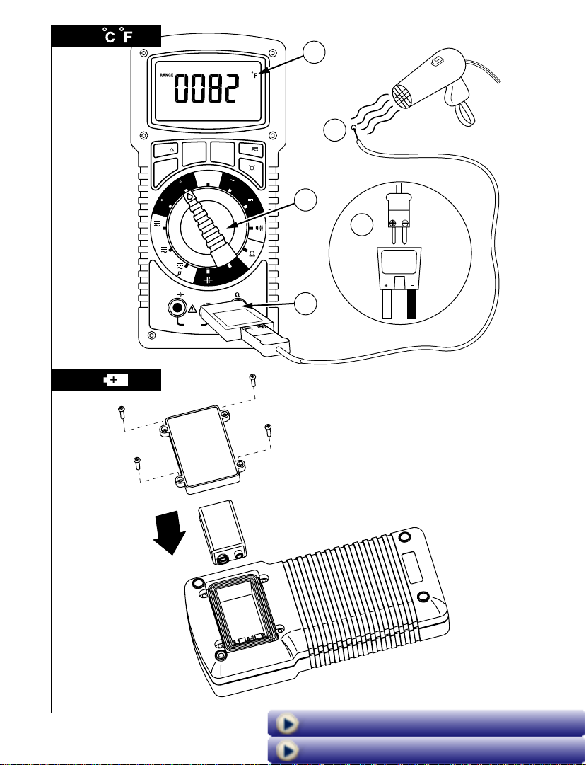
Measuring Temperature (See Figure 9)
1. Set the Function Switch to °C or °F.
2. Connect the K-type thermocouple to a TEMP adapter (TA-1A); match the polarity
of the adapter to the polarity of the thermocouple.
3. Connect the TEMP adapter to the
Note: The HD160C is compatible with all K-type thermocouples. The K-type bead
thermocouple supplied with the meter is not intended for contact with liquids or
electrical circuits.
4. Expose the thermocouple to the temperature to be measured.
5. Read the display.
Temp VΩHz and COM inputs.
Test Equipment Depot - 800.517.8431 - 99 Washington Street Melrose, MA 02176
FAX 781.665.0780 - TestEquipmentDepot.com
Page 12

Button Functions
Display Backlight
Button
AC DC Mode
RANGE
HOLD
REL
(Relative Measurements)
Model HD160C has Digi-GloTM backlighting, one of the best
backlights available in the industry. This button turns the
backlight on and off. To conserve battery life, backlight will
automatically turn off after approximately 60 seconds.
Each press alternately selects the AC or DC mode for the
current function. The selected mode appears on the display
above the button.
Locks the currently displayed range. Each subsequent push
of the button moves to a higher range. From highest range,
the meter returns to the lowest range. The meter functions
in the 4000 count mode when range is locked.
Freezes the reading present on the LCD at the moment
the button is pressed. To use this button feature set up the
meter for the type of measurement and range desired.
Connect the test leads to the circuit/component to be
measured, then press Hold. The LCD reading will freeze and
display “HOLD.” You may now remove the test leads and
the reading will not change until you press Hold again.
The Relative mode displays the difference between the
actual reading and a reference value. It may be used with
any function or range; however, the range must be set
manually. To make a relative measurement first establish
a reference value by measuring a value and then pressing
the REL button after the reading has stabilized. This stores
the measured value as the reference and sets the display
to zero. The meter subtracts the reference value from
subsequent measurements and displays this difference as
the relative value. Measurement values greater than the
reference value will be positive and values less than the
reference value will be negative. To exit the Relative Mode,
Press and hold the REL button for 2 seconds. Select the
proper Range using the RANGE button before enabling the
REL feature. This function will not autorange.
10
Page 13
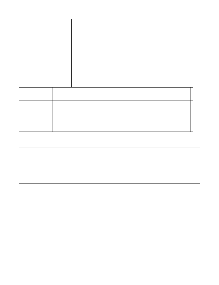
The MIN MAX AVG feature reads and updates the display
to show the maximum, minimum, or average value
measured after you press the MIN MAX AVG button.
Pressing the MIN MAX AVG button for less than 1 second
will put the meter into a mode of displaying the maximum,
MIN MAX AVG
Button Display Value Displayed
MNMX MAX Maximum value after feature activated
< 1 second MNMX MIN Minimum value after feature activated
< 1 second MNMX AVG Average value after feature is activated
< 1 second MNMX Actual reading, min max being recorded.
> 2 seconds
Exit MIN MAX
AVG
minimum, average, or actual readings. Each time the
button is pressed, the meter will cycle to the next display
mode as shown in the table below. Press the MIN MAX AVG
button for more than 2 seconds to disable this feature.
Select the proper Range using the RANGE button before
enabling the MIN MAX AVG feature.
This function will not autorange.
Normal measurement, actual reading
Auto-Power Off
In order to save battery life, your multimeter powers down automatically after
approximately 30 minutes of inactivity. You can turn it back on by turning the function
selector switch to OFF and back to a measuring function. The instrument does not power
down while in Max MIN AVG mode. You can disable Auto Power Off by pressing and
holding the MAX MIN AVG button while turning the meter ON.
Safety Test Leads
The test leads provided with your HD160C meter have shrouded banana plugs to eliminate
the possibility of shock if the plugs accidentally pull out of the meter while making a
measurement. Each set of test leads includes a pair of threaded alligator clips for secure
attachment to the probe tips. Replacement part number for Safety test leads is TL1500.
11
Page 14

Specifications
General Specifications
Display: 4 digit LCD, 9999 counts, with
annunciators, menu features and 41 segment
bargraph.
Polarity Indication: Automatic
Input overload indication: OL, -OL.
Low Battery Indication: B; less than 50 hours
battery life remain, accuracy is no longer
guaranteed
Display Update Rate: 2/sec, nominal; 20/sec for
bargraph.
Oper. Temp. 0 °C to +50 °C @ 0 to 75 % R.H.
Storage Temp: -20 °C to 60 °C @ 0 to 80 % RH,
battery removed
Altitude: 2000 meters - indoor/outdoor use
Temperature coefficient: 0.1 x (spec. accuracy)/
°C (0 °C to 18 °C and 28 °C to 50 °C)
Fuse: F 2 A/1500 V fuse (8 mm x 65 mm),
I.R. 30 kA – Amprobe p/n FP700
Power: Standard 9-volt battery, NEDA 1604, JIS
006P, IEC 6F22
Auto Power-Down: Meter powers down after
approximately 30 minutes of inactivity. Not in
Min/Max function.
Battery Life (typical): 150 hours, alkaline.
Backlight usage consumes extra power and will
decrease battery life significantly. Backlight
auto-off after approx. 60 seconds.
Dimensions, without holster (H x W x D): 200
x102 x59 mm (7.9 in x 4. 0 in x 2.3 in)
Weight (incl. battery): 642 g (22 oz)
Accessories: Heavy Duty Test leads with
threaded alligator clips, battery (installed),
hex wrench (inside holster), Holster with
Magne-Grip strap, Type K thermocouple probe
(TP255A), Temperature Adaptor (TA-1A) and
User Manual.
Case material: Reinforced, high-impact, fire
retardant thermoplastic
Safety: Meets EN 61010-1 Cat IV -1500 V dc or
1000 V ac. Class II. EN 60529:IP67
EMC: Meets EN 61326-1
EMC: This product complies with
requirements of the following European
Community Directives: 89/336/EEC
(Electromagnetic Compatibility) and 73/23/EEC
(Low Voltage) as amended by 93/68/EEC (CE
Marking). However, electrical noise or intense
electromagnetic fields in the vicinity of the
equipment may disturb the measurement
circuit. Measuring instruments will also respond
to unwanted signals that may be present within
the measurement circuit. Users should exercise
care and take appropriate precautions to avoid
misleading results when making measurements
in the presence of electronic interference.
Electrical Specifications
Accuracy at 23 °C ± 5 °C, <75 % RH, guaranteed
for one year.
DC Volts
Ranges: 1000 mV, 10 V, 100 V, 1500 V
Resolution: 0.1 mV in 1000 mV range:
Accuracy: ±(0.1 % rdg + 5 dgt)
Input Impedance: 10 MΩ
CMRR: >120 dB up to 1500 V dc
NMRR: >60 dB at 50 or 60 Hz
OL Protection: 1500 V dc or 1000 V ac rms.
Transient protection: 12 kV impulse (1.2
µS/50 µS) based on EN 61010-1:2001 impulse
requirement for at CAT IV 1000 V/1500V dc
product. This product should not be used in
installations where transients exceed 12 kV.
AC Volts True rms
Ranges: 1000 mV, 10 V, 100 V, 1000 V
Resolution: 0.1 mV in 1000 mV range
Accuracy:
1000 mV (45 Hz to 400 Hz)
±(1.2 % rdg + 10 dgt)
10 V, 100 V (45 Hz to 500 Hz)
±(1.2 % rdg + 10 dgt)
10 V, 100 V (500 Hz to 2 kHz)
±(2.0 % rdg + 10 dgt)
1000 V (45 Hz to 1 kHz)
±(2.0 % rdg + 10 dgt)
Input Impedance: 10 MΩ
Conversion type: True rms, ac coupled 5 % to
100 % of range
Crest factor: ≤ 3
OL Protection: 1500 V dc or 1000 V ac rms
Transient protection: 12 kV impulse (1.2
µS/50 µS) based on EN 61010-1:2001 impulse
requirement for at CAT IV 1000 V product. This
product should not be used in installations
where transients exceed 12 kV
12
Page 15

DC Current
Ranges: 100 µA, 1000 µA, 10mA, 100mA,
400mA, 2A (Auto/Manual ranging)
Resolution: 0.01µA in 100 µA range
Accuracy:
100 µA range; ± (0.5% rdg + 10 dgts)
1000 µA to 400 mA ranges: ± (0.5% rdg + 5
dgts)
2 A ±(1.5% rdg + 10 dgts)range
Input protection: 2 A/1500 V fast blow ceramic
fuse 8×65 mm on A input , FP700
Burden voltage: µA range of 1 mV/1 µA, mA
range of 10 mV/1 mA, 2A range of 500 mV/1A,
500 mV max. (2 V max. on 1000 µA, 100 mA,
400 mA, 2 A ranges)
AC Current True rms
Ranges: 100 µA, 1000 µA, 10 mA, 100 mA,
400 mA, 2 A
Resolution: 0.01 µA in 100 µA range
Accuracy( 45 Hz to 1kHz):
100 µA to 100 mA: ± (1.5 % + 10 dgts)
400 mA: ± (2.0 % + 10 dgts)
2 A: ± (2.5 % + 20 dgts)
Voltage burden: see DC Current
Conversion type: True rms ac coupled 10 to
100% of range
Crest factor: ≤ 3
OL protection: see DC Current.
Resistance
Ranges:1000 Ω, 10 kΩ, 100 kΩ, 1000 kΩ,
10 MΩ, 40 MΩ
Resolution: 0.1 Ω in 1000 Ω range
Accuracy:
1000 Ω to 1000 KΩ ranges: ±(0.5 % rdg
+8 dgts);
10 MΩ range: ± (1.0 % rdg +10 dgts)
40 MΩ range: ± (2.0 % rdg +10 dgts)
Overload protection, all ranges: 1500 V dc
or 1000 V ac rms
Continuity Test
Audible indication: Less than 40 Ω
Response time: 100 ms
Overload protection:1500 V dc or 1000 V ac rms
Capacitance
Ranges: 40 ηF, 400 ηF, 4 µF, 40 µF, 400 uF (3999
counts) ( Auto/Manual ranging )
Resolution: 0.01 ηF
Accuracy: ±(3.0% rdg +10dgts) on 40 ηF, 400 µF
ranges
±(3.0% rdg +5dgts) on 400 ηF to 40 µF ranges
Test voltange: < 1 V
Test Frequency: 1.3 Hz on 40 ηF to 40 µF ranges;
0.7 Hz on 400 µF range
Overload protection: 1500 V dc or 1000 V ac rms
Temperature
Ranges: -20 °C ~ 1300 °C (-4° F ~ 2372 °F) 3999
counts
Resolution: 1 °C, 1 °F
Accuracy: ±(2.0% rdg +4 °C) -20 °C ~ 10 °C
±(1.0% rdg +3 °C)10 °C ~ 200 °C
±(2.0% rdg + 2 °C) 200 °C ~ 1300 °C
±(2.0% rdg + 8 °F) -4 °F ~ 50 °F
±(1.0% rdg + 6 °F) 50° F ~ 400 °F
±(2.0% rdg +4 °F)400 °F ~2372 °F
Overload protection: 1500 V dc or 1000 V ac rms
Frequency
Ranges: 100Hz, 1000Hz, 10kHz, 100kHz,
1000kHz, 10MHz
Resolution: 0.01 Hz on 100 Hz range
Accuracy: ±(0.1% rdg + 5 dgts)
Sensitivity:
3 Hz to 1 MHz: >2.5 V ac rms;
1MHz to 10MHz: >2.5V ac rms, <5V ac rms
Minimum input range:
100 Hz range >3 Hz;
1000 Hz range >30 Hz
Minimum pulse width: > 25 ns
Duty cycle limits: > 30 % and < 70 %
Overload protection: 1500 V dc or 1000 V ac rms
Optional Accessories
TL1500 Test Leads with Alligator Clips
CT235A 1000 A ac/dc Clamp
CT237A 200 A ac/dc Current Clamp
CT238A 20 A ac/dc Current Clamp
VC221B Padded Vinyl Case. Fits meter & holster.
DC205C Deluxe Hard-Shell Carry Case
DC207C Large Deluxe Hard-Shell Carry Case
with extra space for accessories
HV231-10A High Voltage Probe
FP 700 Replacement Fuse, 2 A/1500 V
TA-1A K-type thermocouple, temperature
adapter.
Test Equipment Depot - 800.517.8431 - 99 Washington Street Melrose, MA 02176
FAX 781.665.0780 - TestEquipmentDepot.com
Page 16

Maintenance and Repair
If there appears to be a malfunction during the operation of the meter, the following steps
should be performed in order to isolate the cause of the problem:
1. Check the battery.
2. Review the operating instructions for possible mistakes in operating procedure.
3. Inspect and test the test leads for a broken or intermittent connection.
4. Inspect and test the fuses. See Battery/Fuse Replacement for additional
information.
Except for the replacement of the battery or fuse, or test probes, repair of the multimeter
should be performed only by a Factory Authorized Service Center or by other qualified
instrument service personnel. The front panel and case can be cleaned with a mild solution
of detergent and water. Apply sparingly with a soft cloth and allow to dry completely
before using. Do not use aromatic hydrocarbons or chlorinated solvents for cleaning.
Battery/Fuse Replacement (Figure 10)
Warning
To prevent electrical shock or meter damage, disconnect the meter’s test leads from any
circuit and the meter then turn the meter off before removing the rear case cover.
PRECAUTIONS
• The hex head case screws each have a washer and gasket integral to the meter’s
water/dust-proof integrity. Upon opening, be sure these are retained and replaced
when closing.
• Prying the rear case cover off with a knife or screwdriver is not recommended as this
may damage the case rim flanging and/or gasket thereby destroying the water/dustproof integrity.
• The fuse cover is integral to the EN 61010-1 Cat IV safety rating and must be replaced
to avoid potential shock hazards.
• Battery or fuse replacement should be performed in a clean environment and with
appropriate care taken to avoid contaminating the meter’s interior components.
• There are no user serviceable parts or components on the circuit boards. Disassembly
beyond the instructions list below for battery and/or fuse replacement will void all
warranties.
BATTERY REPLACEMENT
Disconnect the test leads, turn off the meter and remove the holster. Remove the 4 hex head
battery cover screws from the rear case cover using the 2 mm hex wrench as Shown in Figure
10. Replace the battery with a NEDA type1604 or equivalent 9V alkaline battery. Make sure the
battery compartment seal is in good condition and properly aligned before replacing the
cover and screws.
FUSE REPLACEMENT
The fuse is located under the protective cover. Disconnect the test leads, turn off the meter
and remove the holster. Remove the six hex head screws in the face plate using the 2 mm hex
wrench mounted in holster. Remove the rear case cover carefully and place the front of the
14
Page 17

meter face down on a clean padded surface. Lift off cover and carefully remove the fuse by
gently prying under the fuse. Pry out the large fuse by placing a small flat screwdriver under the
fuse’s center using the circuit board edge toward the bottom of the meter as a fulcrum. Do NOT
use the gasket as a fulcrum point as this could permanently disfigure the gasket.
Warning
Use only the same size and type fuse specified. Use of higher amperage or lower voltage or different type fuses could result in
shock, injury and/or damage to the meter. Replacement fuse is:
2 A/1500 V fast blow ceramic size 8 x 65 mm. Amprobe p/n: FP700.
CLOSING THE BATTERY COMPARTMENT
After fuse replacement, replace the fuse cover and the rear case cover; be careful not to
bend or pinch the case rim gasket. Re-install the six hex-head screws with a gasket and
washer and tighten securely with an even amount of torque on each. Do NOT over tighten
as this may strip case threading. Turn on the meter and test operation. If working normally
replace the holster.
Repair Information
All test tools returned for warranty or non-warranty repair or for calibration should be accompanied
by the following: your name, company’s name, address, telephone number, and proof of purchase.
Additionally, please include a brief description of the problem or the service requested and include
the test leads with the meter. Non-warranty repair or replacement charges should be remitted in the
form of a check, a money order, credit card with expiration date, or a purchase order made payable to
Amprobe Test Tools.
In-Warranty Repairs and Replacement – All Countries
Please read the warranty statement and check your battery before requesting repair. During the
warranty period any defective test tool can be returned to your Amprobe Test Tools distributor for an
exchange for the same or like product. Please check the “Where to Buy” section on www.amprobe.com
for a list of distributors near you. Additionally, in the United States and Canada In-Warranty repair and
replacement units can also be sent to an Amprobe Test Tools Service Center (see below for address).
Non-Warranty Repairs and Replacement – US and Canada
Non-warranty repairs in the United States and Canada should be sent to an Amprobe Test Tools
Service Center. Call Amprobe Test Tools or inquire at your point of purchase for current repair and
replacement rates.
In USA In Canada
Amprobe Test Tools Amprobe Test Tools
Everett, WA 98203 Mississauga, ON L4Z 1X9
Tel: 877-AMPROBE (267-7623) Tel: 905-890-7600
Non-Warranty Repairs and Replacement – Europe
European non-warranty units can be replaced by your Amprobe Test Tools distributor for
a nominal charge. Please check the “Where to Buy” section on www.amprobe.com for a list
of distributors near you.
European Correspondence Address*
Amprobe
P.O. Box 1186
5602 BD Eindhoven
Test Tools Europe
The Netherlands
*(Correspondence only – no repair or replacement available from this address. European customers
please contact your distributor.)
15
Page 18
1
2
V
OFF
2 A
mA
A
V
V
Hz
F
C
REL
MIN MAX
AVG
RANGEHOLD
A
HD160C
V
A
Temp
COM
2A MAX
FUSED
MAX
1500V
1000V
IV
CAT
1000 V
Hz
OFF
2 A
mA
A
V
V
Hz
F
C
REL
MIN MAX
AVG
RANGEHOLD
A
HD160C
V
A
Temp
COM
2A MAX
FUSED
MAX
1500V
1000V
IV
CAT
1000 V
Hz
4
V
4
3
3
2
5
2
5
1
1
16
Page 19
3
4
A
A
OFF
2 A
mA
A
V
V
Hz
F
C
REL
MIN MAX
AVG
RANGEHOLD
A
HD160C
V
A
Temp
COM
2A MAX
FUSED
MAX
1500V
1000V
IV
CAT
1000 V
Hz
OFF
2 A
mA
A
V
V
Hz
F
C
REL
MIN MAX
AVG
RANGEHOLD
A
HD160C
V
A
Temp
COM
2A MAX
FUSED
MAX
1500V
1000V
IV
CAT
1000 V
Hz
5
8
5
7
4
8
6
7
9
2
3
1
5
1
4
9
2
3
Test Equipment Depot - 800.517.8431 - 99 Washington Street Melrose, MA 02176
FAX 781.665.0780 - TestEquipmentDepot.com
Page 20
5
6
OFF
2 A
mA
A
V
V
Hz
F
C
REL
MIN MAX
AVG
RANGEHOLD
A
HD160C
V
A
Temp
COM
2A MAX
FUSED
MAX
1500V
1000V
IV
CAT
1000 V
Hz
OFF
2 A
mA
A
V
V
Hz
F
C
REL
MIN MAX
AVG
RANGEHOLD
A
HD160C
V
A
Temp
COM
2A MAX
FUSED
MAX
1500V
1000V
IV
CAT
1000 V
Hz
5
3
4
6
1
2
4
6
5
7
3
2
1
18
Page 21

7
8
OFF
2 A
mA
A
V
V
Hz
F
C
REL
MIN MAX
AVG
RANGEHOLD
A
HD160C
V
A
Temp
COM
2A MAX
FUSED
MAX
1500V
1000V
IV
CAT
1000 V
Hz
OFF
2 A
mA
A
V
V
Hz
F
C
REL
MIN MAX
AVG
RANGEHOLD
A
HD160C
V
A
Temp
COM
2A MAX
FUSED
MAX
1500V
1000V
IV
CAT
1000 V
Hz
5
6
7
4
4
5
3
2
1
1
2
8
3
19
Page 22
20
9
10
OFF
2 A
mA
A
V
V
Hz
F
C
REL
MIN MAX
AVG
RANGEHOLD
A
HD160C
V
A
Temp
COM
2A MAX
FUSED
MAX
1500V
1000V
IV
CAT
1000 V
Hz
K
1
5
4
3
2
Visit us at www.TestEquipmentDepot.com
Back to Amprobe HD110C/HD160C Page
 Loading...