

Page 1
Test Equipment Depot - 800.517.8431 - 99 Washington Street Melrose, MA 02176
TestEquipmentDepot.com
Quick Start Guide
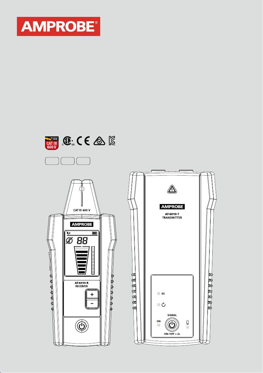
AT-6010 Advanced Wire Tracer
Reliable, precise breaker
identification
Tested by Fluke and safety
certified by 3rd party labs
ENG FRE SPA
Intuitive Transmitter
automatically senses whether
the system is energized or
de-energized
Most accurate wire tracing
in its class with eight
sensitivity modes
Page 2

AT-6010 Advanced Wire Tracer
Page 3

Quick Guide Table of Contents
2. Tracing Energized and De-energized Wires
Connecting Transmitter to Energized w
3.
Identifying Breakers and Fuses
4.
5. Special Application: Finding Shorts
6. Special Application: Finding Breaks
orking system
7. Special Application: Metal Conduit
8. Wire Tracer Specications
9. Included in Wire Tracer Kits
AT-6010 Advanced Wire Tracer
Special Applications:
• GFCI-protected circuit wire tracing
•
Find breaks, openings, and shorts
• Trace wires in metal conduit
• Trace non-metallic pipes and conduits
•
Trace shielded wires
• Trace underground wires
• Trace low voltage wires and data cables
•
Sort bundled wires
• Map circuits using test leads connection
• Trace breakers on system with light dimmers
•
CT-400 signal clamp (optional accessory) to improve accuracy
and performance when there is no access to bar
e conductors
English
See the user manual for further instructions regarding special applications.
Page 4
AT-6010
Tracing Energized and De-energized Wires
Set-up:
1
Test Leads
Proper connection
with separate
ground
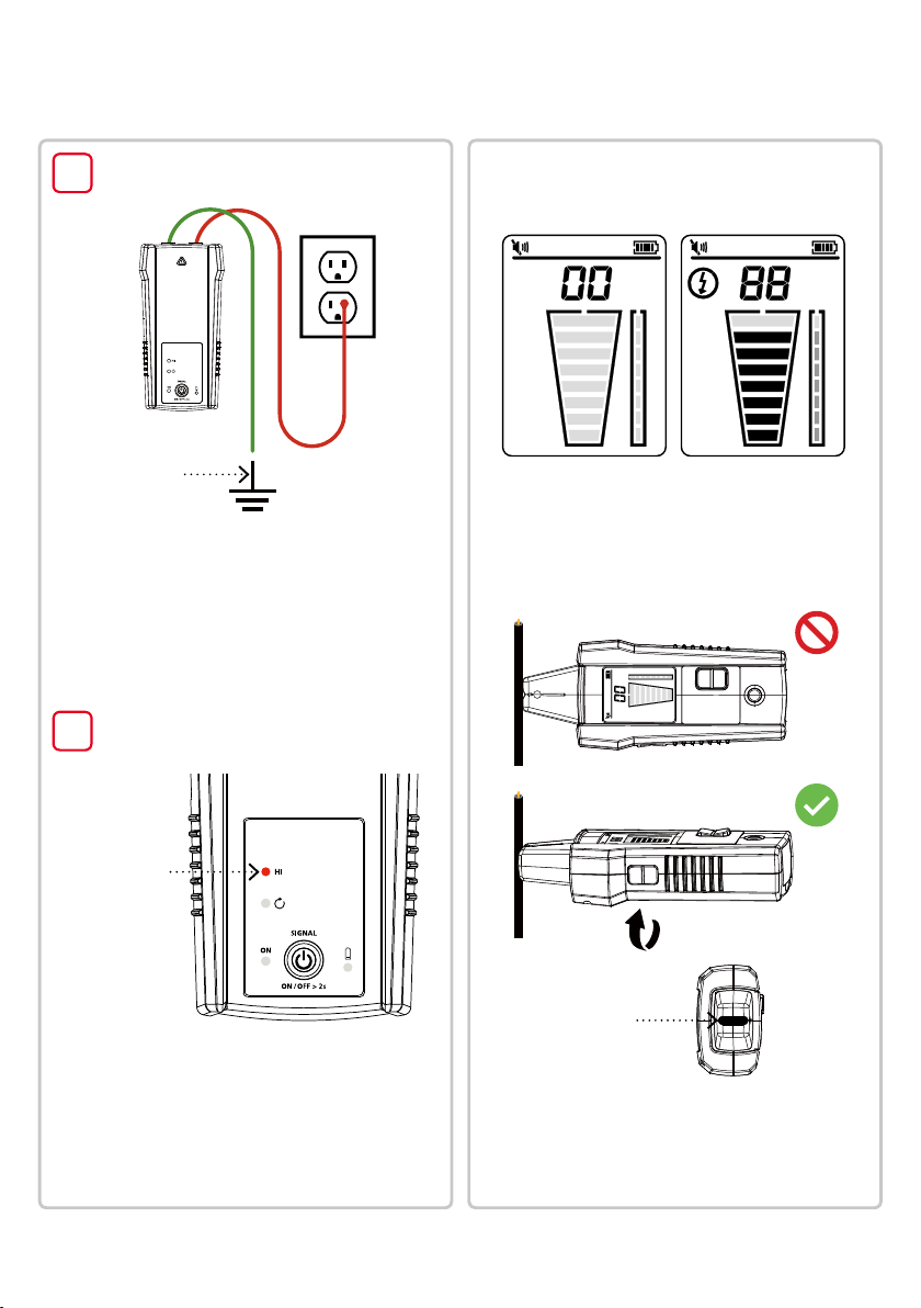
1. Plug the green and red test leads into the Transmitter.
2. Connect the red test lead to the wire being traced,
Energized or De-energized. For receptacles, make
sure to connect the test lead to the hot wire.
The signal will only be transmitted between the
load-side to which the Transmitter is connected and
the source of power.
Connect the green wire to a separate ground.
3.
Set-up:
2
Transmitter
Receiver:
Tracing Mode
Use this mode to easily follow the direction of a wire.
Signal not detected Signal detected
1. Turn on the Receiver. Tracing mode is
automatically activated.
2. Scan the target area with the Tip Sensor to nd the
highest signal level, then begin tracing the detected
wire. Increase or decrease sensitivity of the Receiver
by pressing + or - on the keypad as necessary.
2
Transmitter
indicator showing
signal in
HIGH mode
1. Turn on the Transmitter.
that the test leads are properly connected;
2.
Verify
the red LED voltage status light should be on
for circuits with voltage above 30 V AC/DC, and
it should be off for De-energized circuits below
30 V AC/DC.
3.
HIGH signal mode is automatically activated
when the Transmitter is turned on.
Tip groove
TIP: Align groove on the Tip Sensor with wire
direction for best results while tracing Energized
wires. Signal may be not detected if not properly
aligned. To verify wire direction, periodically
rotate the Receiver 90 degrees. Signal strength
will be the highest when wire is aligned with the
Tip Sensor groove.
Page 5
Advanced Wire Tracer - Quick Guide
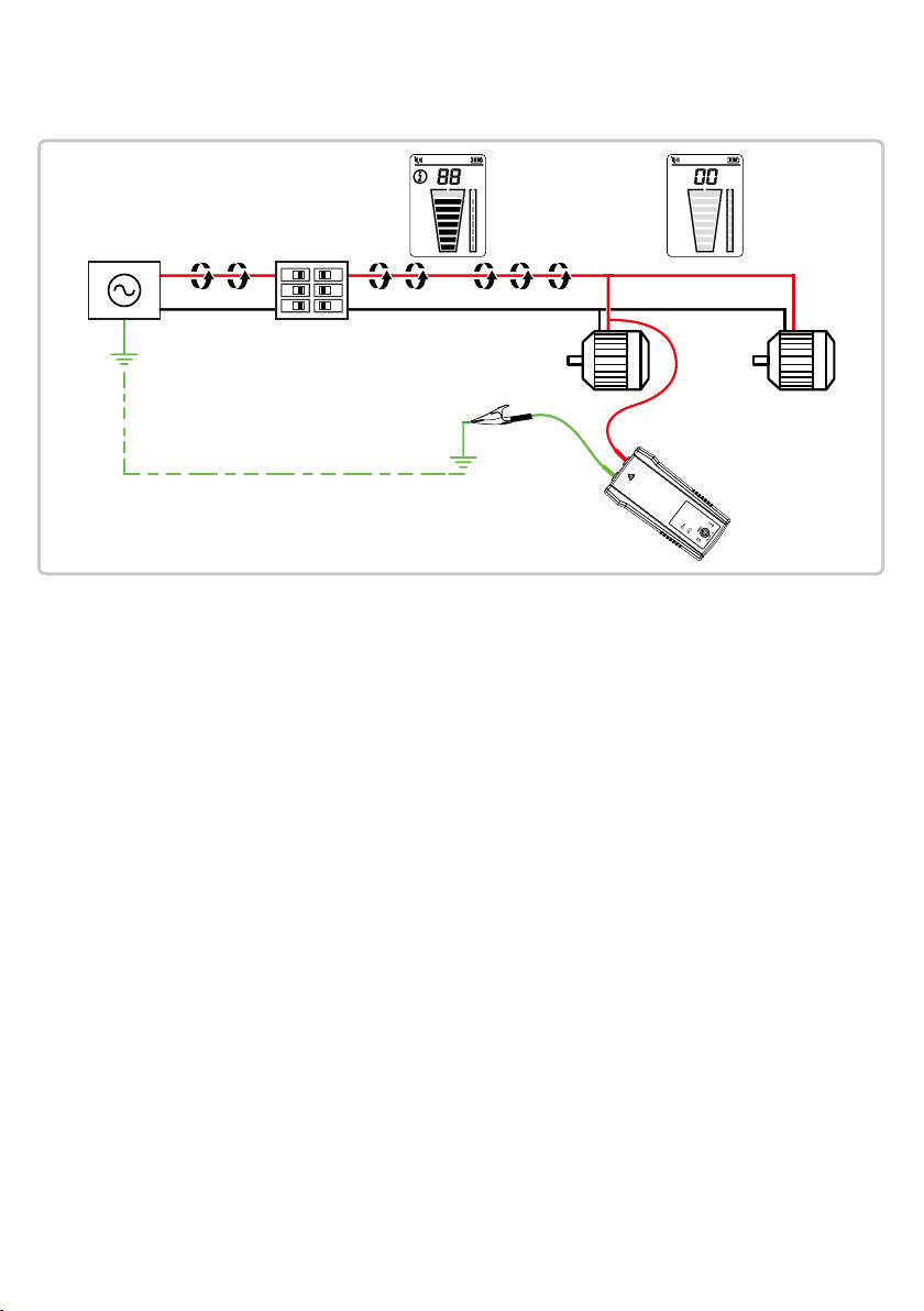
Connecting Transmitter to Energized working system
The Transmitter, with the red test lead, can be directly connected
to the live wire of the working electrical equipment under load
(motor, electronics, etc). Tracing can be performed without
needing to turn off the equipment or switching power off.
3
Page 6
AT-6010
Identifying Breakers and Fuses
Set-up:
Test Leads
Proper connection
with separate
ground
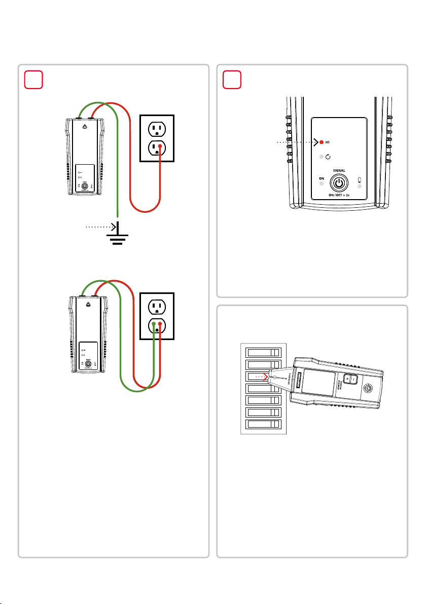
Separate ground connection (Preferred)
Set-up:
21
Transmitter
Transmitter
indicator showing
signal in
HIGH mode
Tur
1.
n on the Transmitter.
that the test leads are properly connected;
2.
Verify
the red LED voltage status light should be on
for circuits with voltage above 30 V AC/DC, and
it should be off for De-energized circuits below
30 V AC/DC.
HIGH signal mode is automatically activated
3.
when the T
ransmitter is turned on.
Receiver:
Breaker Tracing
4
Simplied direct connection
1. Connect the green and red test leads to the
Transmitter using either simplied direct
connection or separate ground connection.
Separate ground connection (preferred): rst
connect the red lead to the Energized hot wire on
the load side of the system. The signal will ONLY
be transmitted between the outlet to which the
Transmitter is connected and the source of power.
Simplied direct connection: connect the test
leads directly to the hot and neutral wires. While
locating a breaker, wires will not be traceable as
the signals will cancel each other out.
2. Connect the green lead to a separate ground.
Align the tip sensor
groove with the breaker
1. Turn on the Receiver.
Tracing mode is automatically activated.
2. Align the groove on the Tip Sensor with the
breaker lengthwise.
3. Scan all breakers in any order to nd a breaker with
the highest signal. Adjust sensitivity by pressing + or on the keypad to show the signal strength near 50 for
the breaker with the highest signal.
4. Rescan all breakers to nd the one with the highest
signal level.
Page 7
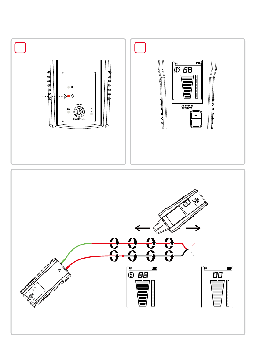
Special Application: Finding Shorts
Advanced Wire Tracer - Quick Guide
Set-up:
1 2
Transmitter
Verify the
Loop LED
is ON.
1.
Connect the Transmitter with the test leads
to the circuit.
2. Switch the Transmitter to Loop mode by
short press of On/Off button. V
Loop LED is ON.
erify that the
Tracing mode:
Tracing a cable to find shorts
1. Start tracing the cable until the signal stops.
2. Verify the place of the fault: move the
Transmitter to the other end of the wire and
repeat tracing from the opposite end. If the
signal stops at the exact same location the
fault has been located.
Set-up:
Receiver
1.
the Receiver. Tracing mode is
Turn on
automatically activated.
Note: This method will be affected
by signal cancellation effect. Expect
a relatively weak signal.
Page 8
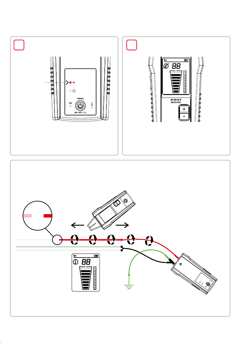
AT-6010
Special Applications: Finding Breaks
Set-up:
1 2
Transmitter
Transmitter
indicator showing
signal in
HIGH mode
1. Ensure the wire is De-energized.
2.
Connect the T
to the circuit.
HIGH signal mode is automatically
3.
activated when the T
ransmitter with the test leads
ransmitter is turned on.
Tracing mode:
Tracing a cable to find
breaks or opens
Set-up:
Receiver
Turn on the Receiver. Tracing mode is
1.
automatically activated.
1. Start tracing the cable until the
signal stops.
Verify the place of the fault:
2.
move the T
end of the wire and repeat tracing
from the opposite end. If the signal
stops at the exact same location the
fault has been located.
ransmitter to the other
6
Note: For best results, ground all
De-energized wires that run in
parallel with the black test lead.
Page 9
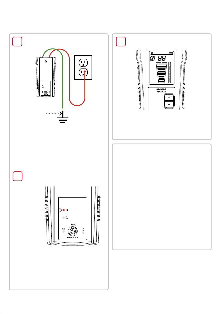
Special Application: Metal Conduit
Advanced Wire Tracer - Quick Guide
Set-up:
1
Test Leads
Proper connection
with separate
ground
1. Connect the green and red test leads to
the Transmitter.
2. Connect the red test lead to the wire being
traced, Energized or De-energized. For receptacles,
make sure to connect the test lead to the hot wire.
The signal will only be transmitted between the
load-side to which the Transmitter is connected
and the source of power.
3.
Connect the green wire to a separate ground.
Set-up:
2
Transmitter
Set-up:
1
Receiver
Turn on the Receiver. Tracing mode is
1.
automatically activated.
Receiver:
Tracing Wires in
Metal Conduit
1. Open junction boxes and use the Receiver
Tip Sensor to detect which wire in the
junction box is carrying the signal.
2. Move from junction box to junction box to
follow the path of the wire.
Transmitter
indicator showing
signal in
HIGH mode
the Transmitter.
Turn on
1.
2.
Verify that the test leads are properly connected;
the red LED voltage status light should be on
for circuits with voltage above 30 V AC/DC, and
it should be off for De-energized circuits below
30 V AC/DC.
3. HIGH signal mode is automatically activated
when the Transmitter is turned on.
Important Notes:
Applying a signal directly to the conduit will send the
signal through all the conduit branches, making tracing
a particular conduit path impossible.
The Receiver is unable to pick up the signal from a
wire through a metal conduit. The metal conduit will
completely shield the tracing signal. The Receiver will be
able to detect wires in a non-metallic conduit. For these
applications follow general tracing guidelines.
Page 10
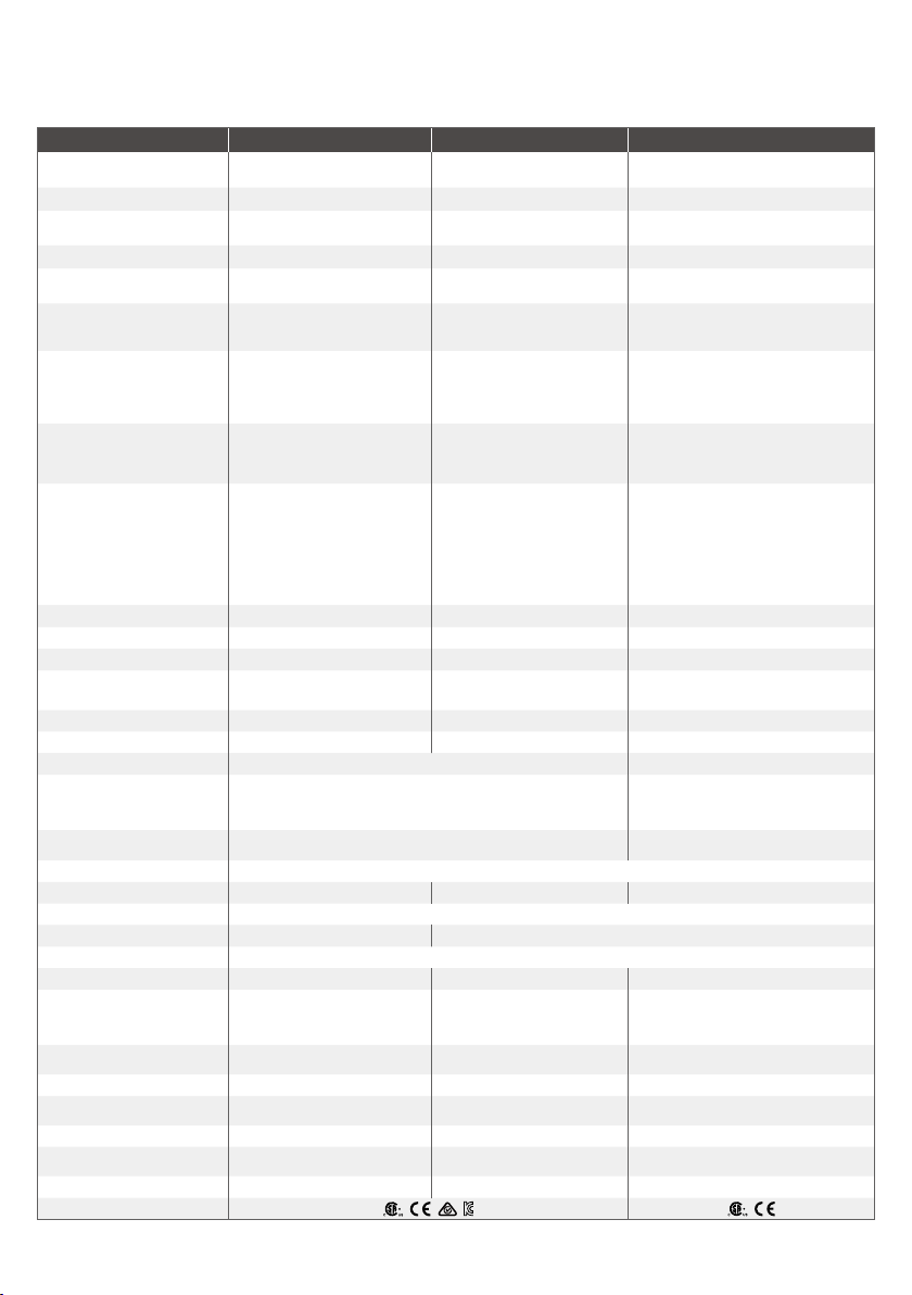
AT-6010
Specications
Measurement Category
Operating Voltage
Operating Frequency
Voltage Detection
Signal Indications
Response Time
Current Output of Signal
(typical)
Signal Voltage Output
(nominal)
Range Detection (open air)
Display size
Display dimensions (W x H)
Display type
Display color
Booting time
Backlight
Operating temperature
Operating humidity
Storage temperature and
humidity
Operating altitude
Transient protection
Pollution degree
IP rating
Drop test
Power supply
Power consumption (typical)
Battery life (typical)
Low battery indication
Fuse
Maximum conductor Size
Dimensions (L x W x H)
Weight
Certications
AT-6010-R Receiver AT-6010-T Transmitter CT-400 Signal Clamp
CAT III 600 V CAT III 600 V
0 to 600 V AC/DC 0 to 600 V AC/DC 0 to 1000 V AC
Energized: 6.25 kHz
De-Energized: 32.768 kHz
N/A > 30 V AC/DC N/A
Numeric bar graph display and
audible beep
Tip Sensor (Energized /
De-energized): 500 ms
Battery voltage monitoring: 5 sec
N/A
N/A
Tip Sensor (Energized):
Max distance via air:
up to 6.1 m (20 ft)
Pinpointing:
approx. 5 cm (1.97 in)
Tip Sensor (De-energized):
Max distance via air:
up to 4.5 m (14.7 ft)
Pinpointing: approx. 5 cm (1.97 in)
LCD 2.5 in (6.35 cm) LEDs N/A
1.45 x 1.93 in (36.72 x 48.96 mm)
Segment LCD LEDs
Black and white
< 3 sec < 2 sec
Yes
-4 °F to 122 °F (-20 °C to 50 °C) 32 °F to 122 °F (0 °C to 50 °C)
45%: -4 °F to <50 °F (-20 °C to <10 °C)
95%: 50 °F to <86 °F (10 °C to <30 °C)
75%: 86 °F to <104 °F (30 °C to <40 °C)
45%: 104 °F to 122 °F (40 °C to 50 °C)
-4 °F to 158 °F (-20 °C to 70 °C), <95% RH -4 °F to 140 °F(-20 °C to 60 °C), <95% RH
N/A
IP 52 IP 40
4 x AA (alkaline) 8 x AA (alkaline)
70 mA
Approx. 25 h
Yes Yes
N/A
N/A
Approx. 7.2 x 2.95 x 1.69 in
(183 x 75 x 43 mm)
Approx. 0.6 lb (0.27 kg) Approx. 1.25 lb (0.57 kg) Approx. 0.25 lb (0.114 kg)
Energized: 6.25 kHz
De-Energized: 32.768 kHz
LEDs N/A
Line/phase voltage monitoring: 1 sec
Battery voltage monitoring: 5 sec
Energized circuit:
HI mode: 60 mA RMS
De-energized circuit:
HI mode: 130 mA RMS
Loop mode: 160 mA RMS
De-energized circuit:
HIGH: 33 V RMS, 140 Vp-p
With CT-400-EUR:
Loop model: 31 V RMS, 120 Vp-p
N/A N/A
N/A N/A
Operating mode LEDs: red
Battery status LEDs: red
N/A N/A
0 to 6561 ft (2000 m)
6.00 kV (1.2/50 μS surge)
Loop mode with Clamp: 90 mA
Consumption without signal
transmission: 10 mA
Hi mode: approx. 25 h
Loop mode: approx. 18 h
1.6 A, 700 V, fast-acting,
Approx. 7.2 x 3.66 x 1.97 in
(183 x 93 x 50 mm)
2
3.28 ft (1 m)
Hi mode: 70 mA
Ø 6x32mm
Yes 1.26 in (32 mm)
AC current measurement: 45 Hz to 400 Hz
1 mA/A for AC current measurement with
75%: 86 °F to <104 °F (30 °C to <40 °C)
45%: 104 °F to <122 °F (40 °C to <50 °C)
CAT IV 600 V,
CAT III 1000 V
Wire tracing: 32.768 kHz
Instantaneous
multimeter
De-energized circuit:
2.4 V RMS, 24 Vp-p
N/A
N/A
N/A
95%: 50 °F to <86 °F (10 °C to <30 °C)
N/A
N/A
N/A
N/A
N/A
N/A
Approx. 5.9 x 2.75 x 1.18 in
(150 x 70 x 30 mm)
8
Page 11
Advanced Wire Tracer - Quick Guide
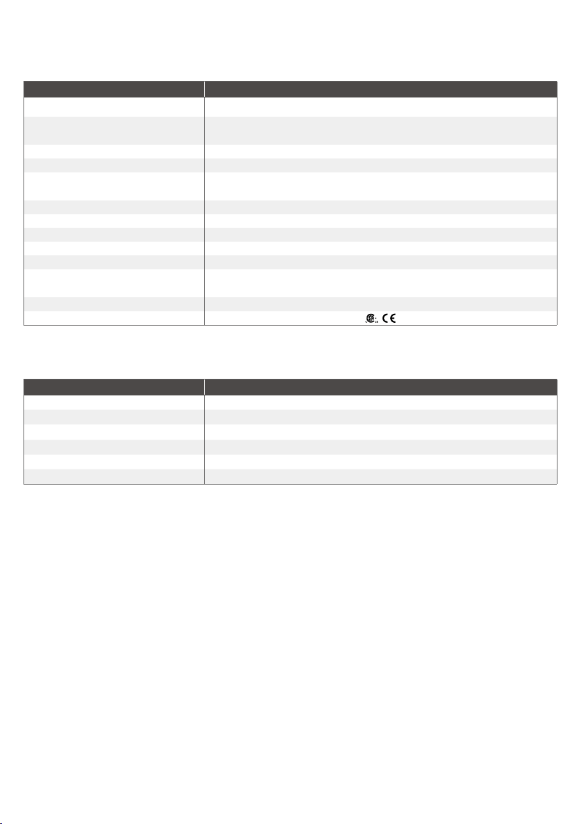
Accessory specications
TL-6000-INTL
Measurement Category
Operating Voltage and Current
Operating Frequency N/A
Operating Temperature 32 °F to 122 °F (0 °C to 50 °C)
Operating Humidity
Storage Temperature and Humidity -4 °F to 140 °F (-20 °C to 60 °C), <95% RH
Operating Altitude 0 to 6561 ft (2000 m)
Pollution Degree 2
IP Rating IP 20
Drop Test 3.28 ft (1 m)
Dimensions
Weight Approx. 0.75 lb (0.34 kg)
Certications
45%: 104 °F to <122 °F (40 °C to <50 °C)
Alligator clips: approx. 3.74 x 1.77 x 0.94 in (95 x 45 x 24 mm)
CAT III (test leads)
CAT IV (alligator clips)
1000 V, 16 A max. (red/green leads)
600 V, 16 A max. (black lead)
600 V, 10 A max. (alligator clips)
95%: 50 °F to <86 °F (10 °C to <30 °C)
75%: 86 °F to <104 °F (30 °C to <40 °C)
Red/black leads: 3.28 ft (1 m)
Green lead: 22.97 ft (7 m)
Included in Wire Tracer Kits
AT-6010-KIT
AT-6010-R Receiver 1
AT-6010-T Transmitter 1
TL-6000-INTL test lead and accessory kit* 1
CC-6010 soft carrying case 1
User manual 1
1.5 V AA (IEC LR6) battery 12
*TL-6000-INTL test lead and accessory kit includes:
• 2 x 1 m test leads (red, black)
1 x 7 m test lead (green)
•
• 2 x Alligator clips (red, black)
• 2 x Outlet blade adapter (red, black)
• 2 x Outlet round adapter (red, black)
Optional accessories:
ADPTR-SCT Socket adapter
HS-1 Magnetic hanger
TL-7000-25M Test lead
CT-400 Signal clamp
9
Page 12

© 2018 - 2019 Fluke Corporation.
All rights reserved.
Printed in the U.S.A.
6010521 A
Specications subject to change
without notice.
 Loading...