

Page 1

AMB-45
Digital Megohmmeter
Insulation Resistance Tester
Users Manual
For detailed specifications and ordering info go to www.TestEquipmentDepot.com
Page 2

AMB-45
Digital Megohmmeter
Insulation Resistance Tester
Users Manual
Page 3

Limited Warranty and Limitation of Liability
Your Amprobe product will be free from defects in material and workmanship for 1 year from the
date of purchase. This warranty does not cover fuses, disposable batteries or damage from accident,
neglect, misuse, alteration, contamination, or abnormal conditions of operation or handling.
Resellers are not authorized to extend any other warranty on Amprobe’s behalf. To obtain service
during the warranty period, return the product with proof of purchase to an authorized Amprobe
Test Tools Service Center or to an Amprobe dealer or distributor. See Repair Section for details.
THIS WARRANTY IS YOUR ONLY REMEDY. ALL OTHER WARRANTIES - WHETHER EXPRESS, IMPLIED
OR STAUTORY - INCLUDING IMPLIED WARRANTIES OF FITNESS FOR A PARTICULAR PURPOSE OR
MERCHANTABILITY, ARE HEREBY DISCLAIMED. MANUFACTURER SHALL NOT BE LIABLE FOR ANY
SPECIAL, INDIRECT, INCIDENTAL OR CONSEQUENTIAL DAMAGES OR LOSSES, ARISING FROM ANY
CAUSE OR THEORY. Since some states or countries do not allow the exclusion or limitation of an
implied warranty or of incidental or consequential damages, this limitation of liability may not apply
to you.
Repair
All test tools returned for warranty or non-warranty repair or for calibration should be accompanied
by the following: your name, company’s name, address, telephone number, and proof of purchase.
Additionally, please include a brief description of the problem or the service requested and include
the test leads with the meter. Non-warranty repair or replacement charges should be remitted in the
form of a check, a money order, credit card with expiration date, or a purchase order made payable
to Amprobe® Test Tools.
In-Warranty Repairs and Replacement – All Countries
Please read the warranty statement and check your battery before requesting repair. During the
warranty period any defective test tool can be returned to your Amprobe® Test Tools distributor
for an exchange for the same or like product.
Non-Warranty Repairs and Replacement – US and Canada
Non-warranty repairs in the United States and Canada should be sent to a Amprobe® Test Tools
Service Center. Call Amprobe® Test Tools or inquire at your point of purchase for current repair and
replacement rates.
Page 4
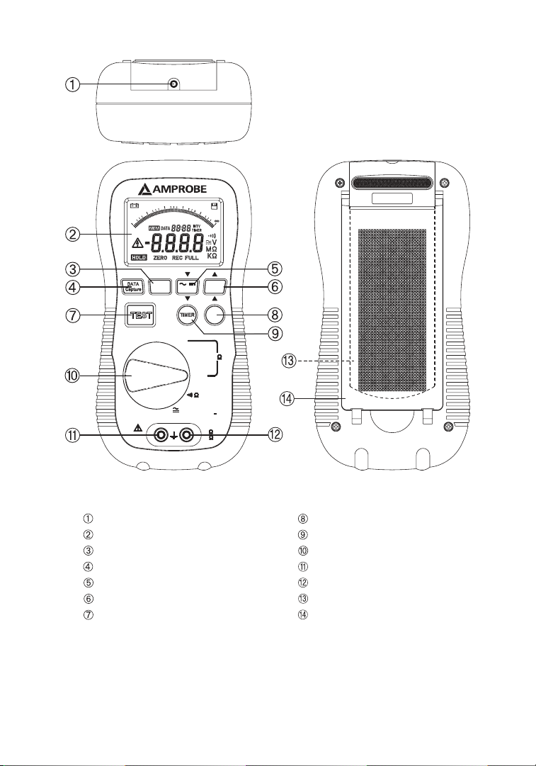
RS232 connector REC interval setup button
LCD Display
Insulation timer button
REC button
Function selection dial
Data capture Button
Black terminal
AC/DC button
Red terminal
Data Hold Button
Battery Compartment Cover
TEST Button
Foldable stand
EXIT
STORE
250V
45
M
1000V CAT
COM
II
V
600V CAT
OFF
V
III
AMB
INTV
HOLD
M
500V
1000V
REC
REC
/
ZERO
RS - 232
700
300
0.2
0
0
1
00
200
9
00
1000
800
5
200
M1
0.5
500
600
10050M
2
5
400
10M
20
1GK
2
500
1
Page 5
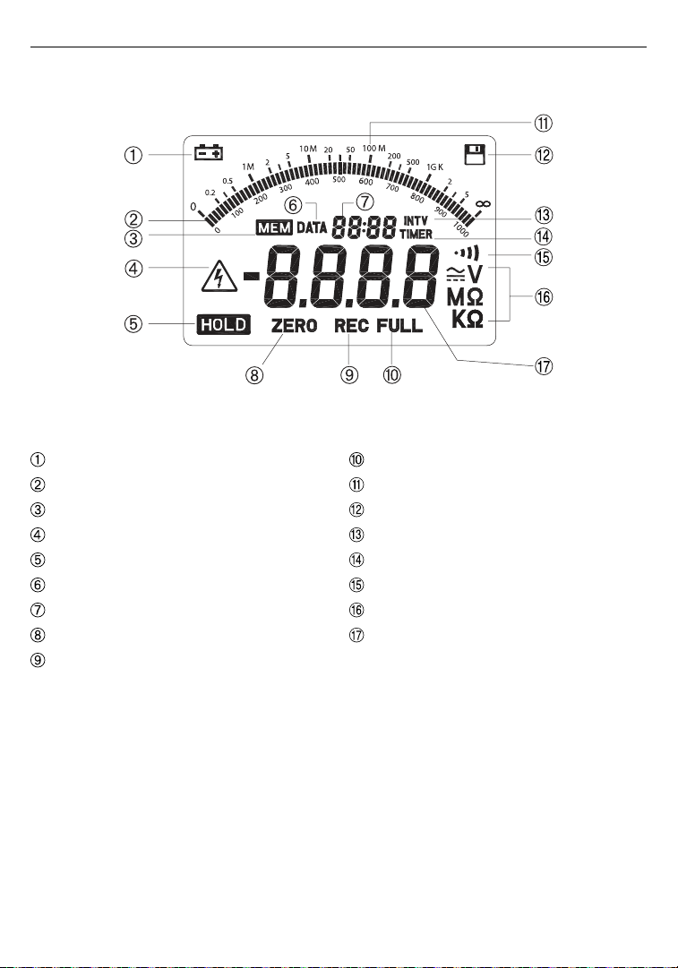
Symbol Definition and Button Location
Low battery
Analog bar display
Data in capture memory
High voltage warning
Data hold
Data capture mode indication
Second digit display
Low ohm zero function
REC in process
Memory full
Analog Bar Scale
Data recording
REC interval symbol
Insulation test timer symbol
Continuity buzzer function
Measuring unit
Main digit display
2
Page 6
AMB-45 Digital Megohmmeter Insulation Resistance Tester
CONTENTS
SAFETY INFORMATION .............................................................................................................. 2
Environment Conditions ..................................................................................................... 2
Maintenance & Cleaning .................................................................................................... 2
Safety Symbols .................................................................................................................... 3
GENERAL SPECIFICATION ............................................................................................................ 3
ELECTICAL SPECIFICATION .......................................................................................................... 4
SYMBOL DEFINITION & BUTTON LOCATION ............................................................................. 5
MEASURING FUNCTION .............................................................................................................. 7
ACV Function ....................................................................................................................... 7
DCV Function ....................................................................................................................... 7
Low Ohm Function and Continuity Function .................................................................... 7
MegaOhm Function ............................................................................................................ 7
AUTO POWER OFF ..................................................................................................................... 10
BATTERY CHANGING ................................................................................................................. 10
FUSE CHANGING ........................................................................................................................ 10
SAFETY SYMBOLS:
�
Caution (Refer to this manual before using the meter)
Dangerous voltages, risk of electric shock.
Meter is protected throughout by double insulation. When servicing, use only specied
replacement parts.
Underwriters Laboratories Inc. [Note: Canadian and US.]
3
Page 7

SAFETY INFORMATION
• Read the following safety information carefully before attempting to operate or service the meter.
• The circuit under test must be de-energized and isolated before connections are made except for voltage
measurement.
Circuit connections
•
• After insulation test, capacitance circuits must be allowed to discharge before disconnecting the test leads.
• To avoid damages to the instrument do not apply the signals, which exceed the maximum limits shown in
the technical specification tables, to the meter.
Do not
•
•
•
•
ENVIRONMENT CONDITIONS:
•
•
•
•
• Relatively humidity 80% max.
• Operation Temperature 0 ~ 40℃
MAINTENANCE & CLEANING:
•
•
use the meter or test leads if they look damaged. Use extreme caution when working around bare
conductors or bus bars.
Use the
meter only as specified in this manual; otherwise, the protection provided by the meter may be
impaired.
Caution when
Before taking
supply and all loads from the circuit.
Installation Categories
Pollution Degree
Altitude up
Indoor use
Only qualified
Periodically wipe the case with a dry cloth. Do not use abrasives or solvents on these instruments.
must not be touched during a test.
working with voltages above 60V DC or 30 V AC RMS. Such voltages pose a shock hazard.
resistance measurements or testing acoustic continuity, disconnect circuit from main power
III 600V, Categories II-1000V
2
to 2000 meters
only
personnel should perform repairs or servicing not covered in this manual.
GENERAL SPECIFICATION:
• Display: 70 x 46mm Big LCD Panel with 60 segments analog bar Indication.
• Over range Indication: “OL” will be shown on the LCD Panel when out of range measurement is made,
except for insulation resistance test, where the “HI“ will be shown.
• Low Battery Indication: The will be show when the battery need to be changed.
• Sampling Rate: 2.5 times/sec Digital Display; 10 times/sec Bar Graph
• Power Source: 1.5V AA size Battery X 8
• Operating Temperature and Humidity: 0℃ to 40℃ (32℉ to 104℉), below 80% RH
• Storage Temperature: -10℃ to 60℃ (14℉ to 140℉)
• Dimension: 230 x 116 x 62 mm; 9 x 4.6 x 2.4 inch
• Weight: Approx. 750g (with battery)
• Accessories: Test Lead, Large Jaw Alligator Clips, Battery, Carrying Case, Software, RS-232 Cable, Users
Manual.
4
Page 8
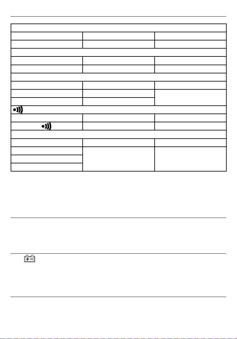
ELECTRICAL SPECIFICATION:
AC Voltage
Range Resolution Accuracy
600V 0.1V 1.5%rdg+5dgts
DC Voltage
Range Resolution Accuracy
600V 0.1V 1%rdg+3dgts
Ω Ohms (Autoranging)
Range Resolution Accuracy
400Ω 0.1Ω
4000Ω 1Ω
Continuity Beeper
Range Active Protection
MΩ ( Autoranging )
Range Resolution Accuracy
4/40/400/4000MΩ ( 250V)
4/40/400/4000MΩ ( 500V)
4/40/400/4000MΩ ( 1000V)
Recording Length: 4000 records
1%rdg+5dgts
40Ω 250Vrms
1KΩ
3%rdg+5dgts < 2GΩ
5%rdg+5dgts < 4GΩ
AUTO POWER OFF
When the tester is idle for thirty minutes, with no function selector or button operation, it will turn itself off
automatically. To turn the tester on again, the user has to turn the function selector to “OFF” position, then the
selected function.
BATTERY CHANGING
When appears on the LCD, the battery need to be replaced with new ones. To replace the battery the
user should turn the function selector to OFF position. Then the user needs to open the battery compartment
cover with a screwdriver. Eight AA 1.5V batteries are needed to replace the old ones. After all Batteries are
changed, put the cover back and fasten the screw.
FUSE CHANGING
When connect the meter under Ohm rang to a source > 10V, the protection fuse will break the circuit and new
one will be needed for replacement. To replace the fuse, user should prepare an F 0.5A 600V fuse. First, the user
should turn the tester off and remove the test leads then remove the Back Cover and Replace the fuse.
5
Page 9

MEASURING FUNCTIONS
ACV FUNCTION:
Turn function selector to voltage range. Connect black test lead to Black terminal and red one to
the Red terminal. Connect test lead to the test circuit in parallel. Operator can hold the reading by
pressing the
DCV FUNCTION:
Turn function selector to voltage range. Connect black test lead to Black terminal and red one to the Red
terminal.
Press the
parallel. One can hold the reading by pressing the
LOW OHM FUNCTION AND CONTINUITY FUNCTION:
Turn function selector to Ohm range. Connect black test lead to Black terminal and red one to the Red terminal.
Connect test lead to the test circuit in parallel. If the reading is less than 40 Ohm, the continuity beeper will
sound.
One may null the lead resistance (under 40 Ohm) by shorting the test lead than press the
the lead resistance is recorded a ZERO symbol will display on the LCD. Press
normal operation. If the lead resistance is great than 40Ω, the error beeping will sound. Because the test current
provided by the meter could reach 200mA, do not use this range to test electronic component like diode,
transistor or fuse.
key.
button to change the mode form ACV to DCV function. Connect test lead to the test circuit in
key.
key. When
key again to go back to
Caution:
Before measuring, verify the circuit is not live by voltage function
MEGAOHM FUNCTION:
Turn the function selector to the desired test voltage range. The LCD will display “----” to indicate the tester is
standing by. Connect black test lead to Black terminal and red one to the Red terminal. Connect test lead to the
test circuit in parallel. One may take the measuring under manual power mode or power lock mode:
6
Page 10

• Manual Mode: If the timer symbol and setup is not shown on the center of LCD, the tester is under manual
mode. Press the test key to activate the test voltage source and the measuring will stop after it got the first
stable reading or the
the high voltage output. A series of beeping with shorter period indicate the discharging in progress. When
the beeper stops, the discharge is completed. The test result will be held on the display automatically.
Lock Mode:
•
timer and setup will be shown in the center of LCD. Press the test button once to activate the test source
and the testing down counter will be shown in the 2nd digital display. A periodic beeping will warn the
high voltage output. The test process can be stop by pressing the
down counter reaches zero. A series of beeping with shorter period indicate the discharging in progress.
hen the beeper stops, the discharge is completed. The test result will be held on the display automatically.
Press the
is pressed again before a stable reading is reached. A periodic beeping will warn
button to enter or exit the Power Lock operation mode. Under this mode the
button again or when the testing
Caution:
Before measuring, verify the circuit is not live by voltage function.
Do not start the test before the lead is connected to the test circuit properly.
Do not remove the test leads from the test circuit before the discharge process is completed.
Setup Timer: When
•
sing
for 2 seconds. The timer setup will blink in LCD and it can be changed by and keys.
Pressing these keys one time will change the setup by one second and pressing these keys for more than
two seconds the value will change continuously. Once the setup is done, the user needs to press the timer
again to store the value into the memory.
• Setup REC interval: The user can setup the REC interval by pressing
LCD and it can be changed by
one second and pressing these keys for more han two seconds the value will change continuously. Once the
setup is done, the user needs to press the timer again to store the value into the memory.
Start/Stop REC
•
the user can start the REC function by pressing
down counter will also be shown in LCD to forecast the next data sampling time. When the second that the
recording occurs, a disk symbol will be shown to indicate this process. When the function selector is under
insulation ranges, the user can set the REC mode only before the measuring start. If the REC mode is set, a
measuring will start the REC process automatically.
Data Capture
•
enter data capture window. The tester will automatically searched the next available capture memory
to store the reading or the user can browse up and down by press the
address is chosen, the user need to press
dow by press
Erase Data
•
and hold
When it is done, message
the function selector is under insulation ranges, the user can setup the timer by pres-
. The interval setup will blink in
and keys. Pressing these keys one time will change the setup by
measuring DATA: When the function selector is under voltage and low resistance ranges,
key. The REC symbol will display in the LCD. The REC
Function: When the user want to store a reading on the LCD, he can press
and keys. Once the
key to store reading. The user can exit data capture win-
key again.
Memory: The user can erase all the memory in the following process. Turn the tester off. Press
key then turn on the tester. will be shown to indicate the erasing is under process.
will be shown in the LCD and the user can release the key.
key to
7
 Loading...