

Page 1

Users Manual
ACD-14 PLUS
ACD-14 TRMS-PLUS
Clamp-on Multimeter
With Dual Display
For detailed specifications and ordering info go to www.TestEquipmentDepot.com
Page 2

ACD-14 PLUS
ACD-14 TRMS-PLUS
Clamp-on Multimeter With Dual Display
Users Manual
Page 3
1
MAX 600A
MAX
HOLD
ON
OFF
SELECT
MAX
COM
A
Hz
ACD-14 PLUS
!
!
A
600V CAT III
kM
Hz
℉
℉
©
m
n
%
kM
Hz
℉
©
m
n
%
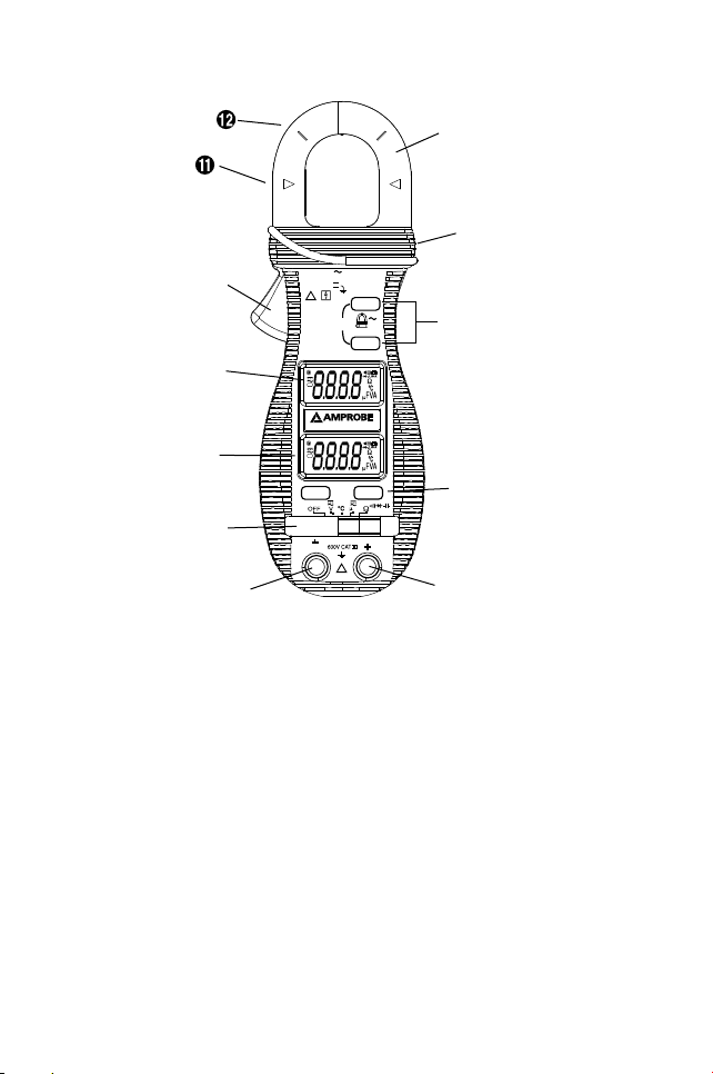
Features of this instrument
1) Transformer Clamp Jaw for AC current magnetic field pick up
2) Hand/Finger Barrier to indicate the limits of safe access of the meter during
measurement
3) Push-buttons for special functions & features. Also as power ON/OFF buttons
for ACA function in Twin Display Models
4) Push-buttons for special functions & features on Slide-switch Selector functions
5)
Input Jack
for all functions EXCEPT non-invasive ACA current function
6)
Common (Ground
reference) Input Jack for all functions
7) Slide-switch Selector
to turn the power ON/OFF and Select a function
8)
3-3/4 digits
4000 counts LCD display(s)
9)
3-3/4 digits
display for ACA
10)
Jaw trigger
for opening the transformer clamp jaw
11)
Jaw center
Indicators, at where best ACA accuracy is specified
12)
Jaw marking
lines for ACA position error indication
➊
➓
➒
➑
➐
➏
➎
➍
➌
➋
Page 4

2
Limited Warranty and Limitation of Liability
Your Amprobe product will be free from defects in material and workmanship for 1
year from the date of purchase. This warranty does not cover fuses, disposable batteries
or damage from accident, neglect, misuse, alteration, contamination, or abnormal
conditions of operation or handling. Resellers are not authorized to extend any other
warranty on Amprobe’s behalf. To obtain service during the warranty period, return the
product with proof of purchase to an authorized Amprobe Test Tools Service Center or
to an Amprobe dealer or distributor. See Repair Section for details. THIS WARRANTY
IS YOUR ONLY REMEDY. ALL OTHER WARRANTIES - WHETHER EXPRESS, IMPLIED OR
STAUTORY - INCLUDING IMPLIED WARRANTIES OF FITNESS FOR A PARTICULAR PURPOSE
OR MERCHANTABILITY, ARE HEREBY DISCLAIMED. MANUFACTURER SHALL NOT BE
LIABLE FOR ANY SPECIAL, INDIRECT, INCIDENTAL OR CONSEQUENTIAL DAMAGES OR
LOSSES, ARISING FROM ANY CAUSE OR THEORY. Since some states or countries do not
allow the exclusion or limitation of an implied warranty or of incidental or consequential
damages, this limitation of liability may not apply to you.
Repair
All test tools returned for warranty or non-warranty repair or for calibration should be
accompanied by the following: your name, company’s name, address, telephone number,
and proof of purchase. Additionally, please include a brief description of the problem or
the service requested and include the test leads with the meter. Non-warranty repair or
replacement charges should be remitted in the form of a check, a money order, credit
card with expiration date, or a purchase order made payable to Amprobe® Test Tools.
Non-Warranty Repairs and Replacement – US and Canada
Non-warranty repairs in the United States and Canada should be sent to a Amprobe®
Test Tools Service Center. Call Amprobe® Test Tools or inquire at your point of purchase
for current repair and replacement rates.
In-Warranty Repairs and Replacement – All Countries
Please read the warranty statement and check your battery before requesting repair.
During the warranty period any defective test tool can be returned to your Amprobe®
Test Tools distributor for an exchange for the same or like product.
Page 5
3
ACD-14 PLUS & ACD-14 TRMS-PLUS
Clamp-on Multimeter With Dual Display
Contents
Instrument Familiarization ............................................................................................ 1
Warranty and Repair ....................................................................................................... 2
Symbols ............................................................................................................................. 3
Introduction. ..................................................................................................................... 4
Warnings and Precautions ............................................................................................... 4
Unpacking and Inspection ............................................................................................... 5
Operation .........................................................................................................................5
Maintenance and Troubleshooting ................................................................................. 9
Battery Replacement. ..................................................................................................... 10
Specications ................................................................................................................. 10
Figures ............................................................................................................................. 15
SYMBOLS
Caution! Refer to the explanation in this Manual
Earth (Ground)
Double Insulation or Reinforced insulation
AC--Alternating Current
DC--Direct Current
Conforms to relevant Australian standards
Underwriters Laboratories Inc. [Note: Canadian and US.]
Complies with European Directives
Application around and removal from hazardous live conductors
is permitted
Do not dispose of this product as unsorted municipal waste
Page 6

4
Introduction
The ACD-14 PLUS and ACD-14 TRMS-PLUS are digital clampmeters that measure both AC
and DC voltage, AC current, Resistance, Frequency, Continuity and Diode Test. Frequency
can be measured in the voltage and current modes.
WARNINGS AND PRECAUTIONS
Safety Information
•
The ACD-14
PLUS Series Digital Clampmeters conform to EN61010-1:2001; EN61010-
2-032:2002; CAT III 600 V, class 2 and pollution deg.2
•
This instrument
is EN61010-1 certified for Installation Category III (600V). It is recommended for use in distribution level and fixed installations, as well as lesser installations, and not for primary supply lines, overhead lines and cable systems.
•
Do not
exceed the maximum overload limits per function (see specifications) nor the
limits marked on the instrument itself. Never apply more than 600 Vdc/600 V ac rms
between the test lead and earth ground.
WARNING
•
Before and
after hazardous voltage measurements, test the voltage function on a
known source such as line voltage to determine proper meter functioning.
•
Disconnect the
test leads from the test points before changing meter functions.
•
Inspect the
Clampmeter, test leads and accessories before every use. Do not use any
damaged part.
•
Never ground
yourself when taking measurements. Do not touch exposed circuit ele-
ments or test probe tips.
•
Do not
operate the instrument in an explosive atmosphere.
•
To reduce the risk of fire or electric shock, do not expose this product to rain or moisture.
•
The meter
is intended only for indoor use. To avoid electrical shock hazard, observe
the proper safety precautions when working with voltages above 60 VDC or 30 VAC
rms. These voltage levels pose a potential shock hazard to the user.
•
Before and
after hazardous voltage measurements, test the voltage function on a
known source such as line voltage to determine proper meter functioning.
•
Keep your
hands/fingers behind the hand/finger barriers (of the meter and the test
leads) that indicate the limits of safe access of the hand-held part during measurement.
•
Inspect test
leads, connectors, and probes for damaged insulation or exposed metal
before using the instrument. If any defects are found, replace them immediately.
•
This Clamp-on
meter is designed to apply around or remove from uninsulated
hazardous live conductors. Individual protective equipment must be used if
hazardous live parts of the installation could be accessible.
•
Exercise extreme
caution when: measuring voltage >20 V // current >10 mA // AC
power line with inductive loads // AC power line during electrical storms // current,
Page 7

5
when the fuse blows in a circuit with open circuit voltage >1000 V // servicing CRT
equipment.
• Remove test leads before opening the case to change the battery.
• Disconnect circuit power and discharge all high-voltage capacitors before testing
resistance,continuity, diodes, or capacitance.
•
To avoid
false readings, which could lead to possible electric shock or personal
injury, replace the batteries as soon as the low battery indicator () appears.
Unpacking and Inspection
Your shipping carton should include:
1 Digital clamp meter
1 Carrying case
1 Test lead set (one black, one red)
1 Two coin cell batteries
1 Manual
If any of the items are damaged or missing, return the complete package to the place of
purchase for an exchange.
OPERATION
CAUTION
The Hz button will alternate the display between the voltage function selected and
frequency reading.
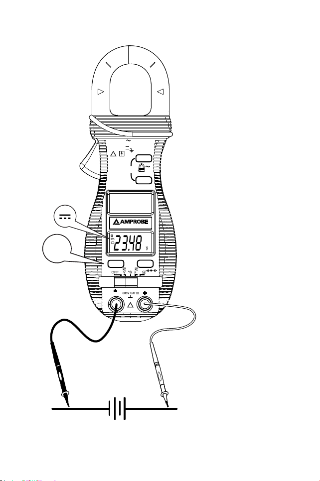
Measuring DC Voltage - See Figure 1
1.
Set the
Function Switch to V.
2. Connect the test leads: Red to +, Black to COM.
3. Connect the test probes to the circuit test points.
4. Read the
display, and if necessary, correct any overload (0L) conditions.
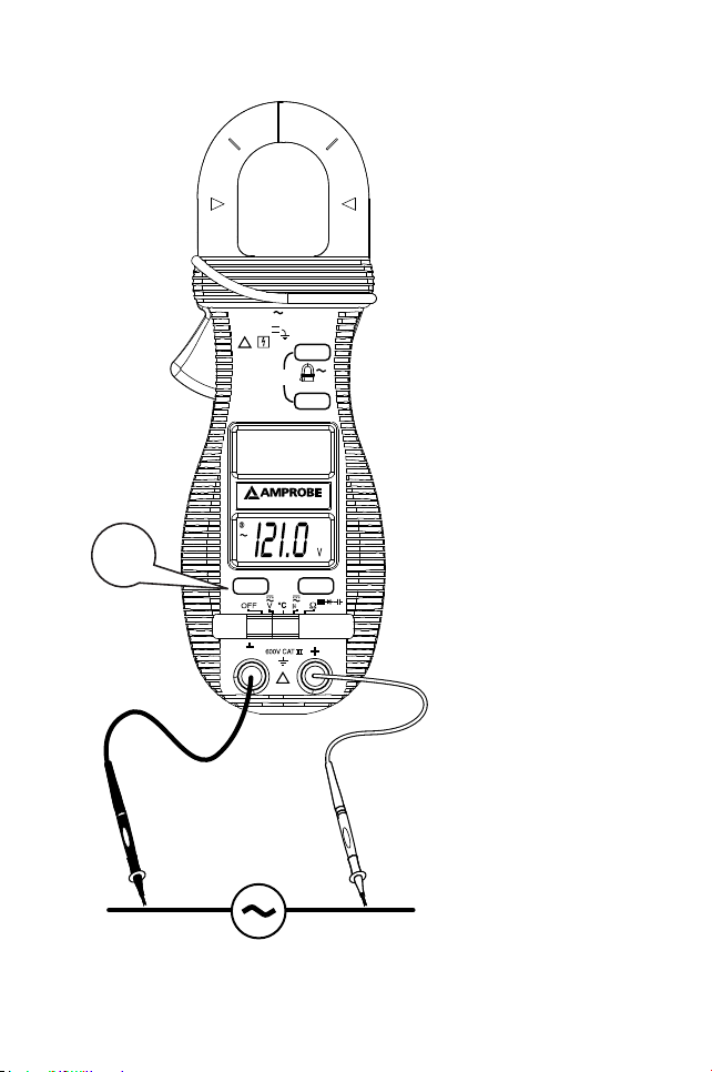
Measuring AC Voltage - See Figure 2
1. Set the Function Switch to V.
2. Connect the test leads: Red to +, Black to COM.
3. Connect the test probes to the circuit test points.
4. Read the display, and if necessary, correct any overload (0L) conditions.
Page 8

6
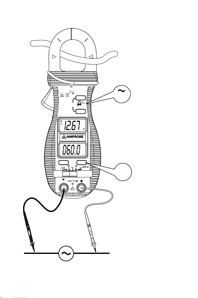
Measuring AC Current - See Figure 3
1. Set the Function Switch to A position.
2. Open spring-loaded clamp by pressing the lever on left side of meter.
3.
Position clamp around one wire or conductor and release the clamp lever. Make sure
that the clamp is entirely closed. The clamp must be positioned around only one conductor. If it is placed around two or more current carrying conductors, the reading is
FALSE.
4. Read the displayed value, and if necessary, correct any overload (0L) conditions.
Measuring Frequency - See Figure 3
The Voltmeter detects the frequency of the voltage applied to the test leads.
1. Set-up AC voltage measurement and press the Hz button.
2. Read the frequency value on the display .
CAUTION
Using the Resistance, Continuity, Diode or Capacitance functions on a live circuit will
produce false results and may damage the instrument. In many cases the suspected
component must be disconnected from the circuit to obtain an accurate measurement
reading.
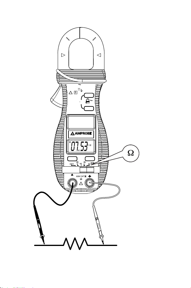
Measuring Resistance - See Figure 4
1. Set the Function Switch to Ω.
2. Connect the test leads: Red to +, Black to COM.
3. Turn off power to the circuit being measured.
4. Discharge any capacitors that may inuence the reading.
5. Connect the test probes across the resistance.
6. Read the display. If 0L appears on the highest range, the resistance is too large to be
measured or the circuit is an open circuit.
Page 9

7
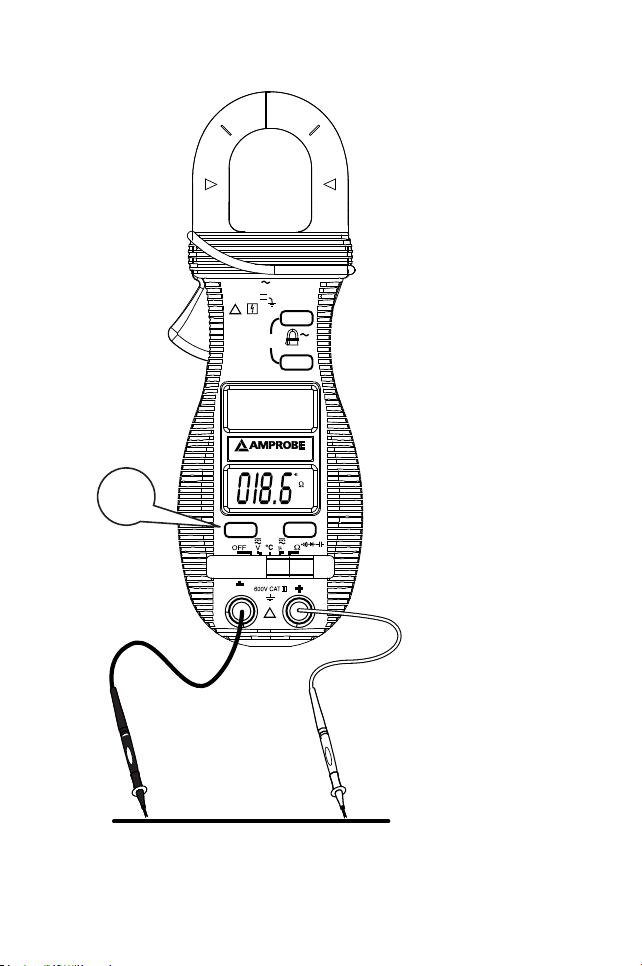
Continuity Testing - See Figure 5
1. Set the Function Switch to Ω and press the SELECT button until is displayed.
2.
Connect the
test leads: Red to +, Black to COM.
3.
Turn off
power to the circuit being measured.
4.
Discharge any
capacitors that may influence the reading.
5.
Connect the
test probes across the resistance or the two points of test.
6.
Listen for
the tone that indicates continuity (>10 Ω and < 120 Ω).
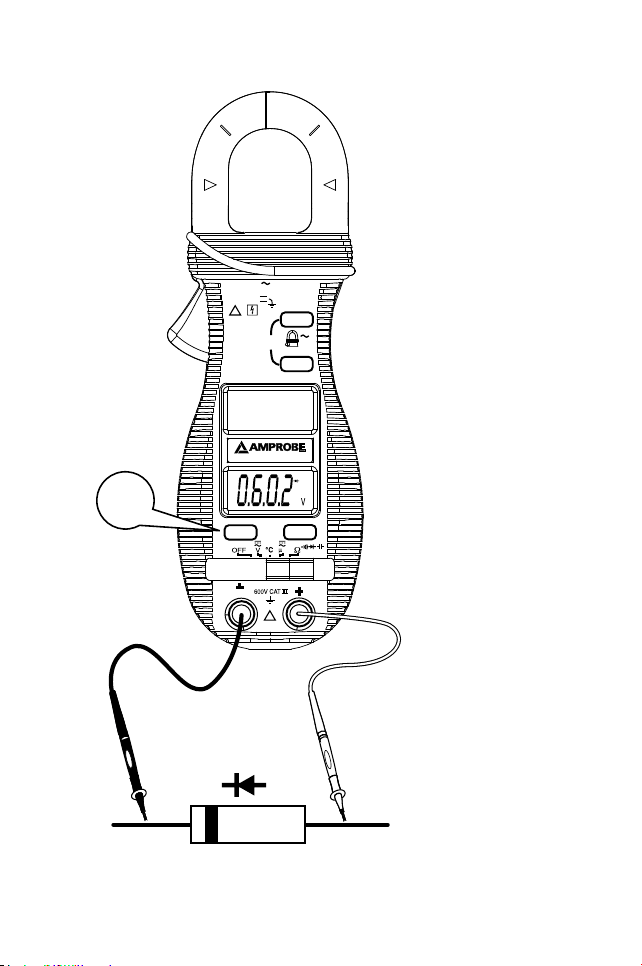
Testing Diodes - See Figure 6
1.
Set the
Function Switch to Ω and press the SELECT button until is displayed.
2.
Connect the
test leads: Red to +, Black to COM.
3.
Turn off
power to the circuit being measured.
4.
Free at
least one end of the diode from the circuit.
5.
Connect the
test probes across the diode noting polarity.
6. Read the
display. A good diode has a forward voltage drop of about 0.6 V. An open
or reverse biased diode will read .0L.
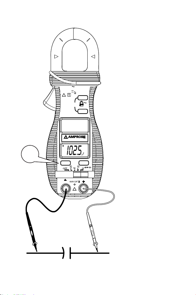
Measuring Capacitance - See Figure 7
1.
Set the
Function Switch to Ω and press the SELECT button until is displayed.
2. Connect the test leads: Red to +, Black to COM.
3.
Turn OFF
power to the circuit being measured.
4.
Discharge the
capacitor using a 100 kΩ resistor.
5.
Free at least one end of the capacitor from the circuit.
6. Connect the
test probes across the capacitor.
7.
Read the display.
8. Relative zero
mode can be used to zero out the parasitic capacitance of the leads
and the internal protection circuitry of the meter when measuring low capacitance
in the order of Pico Farad (pF).
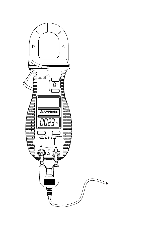
Measuring Temperature - See Figure 8
1.
Set the Function Switch to °F / °C and press the SELECT button until correct temperature range is displayed.
2. Connect the
thermocouple to the input jacks: + to +, - to COM.
You can also use a plug adapter TA-1A (optional purchase) with banana pins to type-K
socket to adapt other type-K standard mini plug temperature probes.
Page 10

8
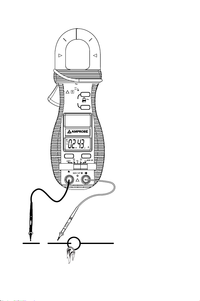
Measuring μA Current - See Figure 9
1.
Set the
Function Switch to and press the SELECT button for AC or DC is displayed.
2. Connect the test leads: Red to +, Black to COM.
3. Turn OFF power to the circuit being measured and break the circuit for connecting
test leads.
4.
Turn ON
the circuit and read the display.
μA Current function
Application notes:
The DCμA function is designed especially for HVAC/R ame sensor applications. The
0.1μA resolution is useful for identifying the minute current changes in ame detector
applications. Flame signal current check should indicate steady ame signal of at least
2μA for a rectication type, or 1.5μA for an ultraviolet type (8μA for self checking
systems). If a ame signal current with inadequate strength or uctuation beyond 10%,
check the following to avoid the risk of unwanted ame relay dropout :
1-1) For gas or oil flames (Minipeeper):
• Low supply voltage
• Detector location
• Defective detector wiring
• Dirty viewing windows
• Faulty Minipeeper
1-2) For oil flames (Photocell):
• Detector location & wiring
• Smoky flame or poorly adjusted air shutter
• Faulty Photocell
• Temperature over 165 °F (74 °C) at photocell
1-3) For gas flames (Flame Rod):
• Ignition interference (A flame signal current difference with the ignition both on
and off greater than 0.5μA indicates the presence of ignition interference)
• Insufficient ground (must be at least 4 times the detector area)
• Flame lifting off burner head (ground), or not continuously in contact with the
flamerod
•
Temperature in
excess of 600 °F (316 °C) at the flame electrode insulator causing
short to ground.
Page 11

9
FEATURES
HOLD / MAX
The HOLD feature freezes the display when the button is pressed. The MAX feature
compares and displays the measured maximum value as fast as 30ms with auto-ranging
capability.
HOLD
Press the HOLD button momentarily toggles to hold mode for the ACA function. To
release the HOLD feature momentarily press the HOLD button.
MAX
Press the HOLD button for 1 second or more activates the MAX HOLD feature for the
ACA function. To release the MAX HOLD feature press the HOLD button for 1 second or
more.
Auto Power Off (APO)
When the meter is on, the Auto Power Off (APO) feature will switch the meter into a
sleep mode automatically to extend battery life after approximately 30 minutes of no
slide-switch nor push button operations. To wake up the meter from APO, press the
buttons momentarily or set the slide-switch to the OFF position and then slide back on
again. Always set the slide-switch to the OFF position manually when the meter is not in
use.
MAINTENANCE
WARNING
To avoid electrical shock, disconnect the meter from circuit, remove the test leads from
the input jacks and turn OFF the meter before opening the case. Do not operate the
meter with open case.
Trouble Shooting
If the instrument fails to operate, check batteries and test leads etc., and replace as
necessary. Double check operating procedure as described in this user’s manual.
The voltage and resistance measurement circuits are protected by fusible resistors and
a parallel high resistance path. If the instrument voltage-resistance input terminal has
been subjected to high voltage transients (caused by lightning or switching surges in the
system), the series fusible input resistors will open like fuses and the voltmeter will read
approximately 85% of the actual value and cause the resistance range to not work. The
meter voltage reading (approximately 15% low) will let the user know that the meter has
been damaged, and the circuit under test is active.
Page 12

10
Refer to the LIMITED WARRANTY section for obtaining warranty or service.
Cleaning and Storage
Periodically wipe the case with a damp cloth and mild detergent; do not use abrasives
or solvents. If the meter is not to be used for periods of longer than 60 days, remove the
battery and store separately.
Battery replacement
The meter uses two 3V IEC-CR2032 coin batteries. Remove the test leads and loosen the
two screws from the case bottom and remove the bottom case. Slide the battery out the
side of the holder and replace with a new battery (observe polarity). Replace the bottom
case. Re-fasten the screws.
GENERAL SPECIFICATIONS
Display: 3-3/4 digits 4000 counts LCD display
Update Rate: 3 per second nominal
Polarity: Automatic
Operating Temperature: 0 °C to 40 °C; < 80% RH for temperature up to 31 °C decreasing
linearly to 50% RH at 40 °C
Altitude: Operating below 2000m; Indoor use
Storage Temperature: -20 °C to 60 °C, < 80% RH (with battery removed)
Temperature Coefficient: nominal 0.15 x (specied accuracy)/°C @ (0 °C ~ 18 °C
or 28 °C ~ 40 °C)
Low Battery: Below approx. 2.4V
Power Supply: 2 each 3V coin battery IEC-CR2032
Power Consumption: 2.8 mA typical except that 3.3 mA typical for ACA function
APO Timing: Idle for 30 minutes
APO Consumption: 5μA typical on all functions except that 40μA typical on voltage
function
Dimension: 190 x 63 x 32 mm (7.4 x 2.5 x 1.3 in)
Weight: 207 gm (.5 lb.)
Jaw Opening & Conductor Diameter: max 26 mm (1”)
Accessories: Test leads (pair), batteries, user’s manual, soft carrying case, and banana plug
type-K bead probe
Special Features: 30ms Max Hold; Data Hold; Simultaneous A+V, A+Hz
Page 13
11
Safety : Meets EN61010-2-032, UL61010B-2-032, IEC61010-1 2nd Ed., EN61010-1 2nd
Ed., UL61010-1 2nd Ed. CAT III-600 Volts AC & DC; Pollution degree : 2
EMC: Conforms to EN61326-1.
This product complies with requirements of the following European Community
Directives: 89/ 336/ EEC (Electromagnetic Compatibility) and 73/ 23/ EEC (Low Voltage)
as amended by 93/ 68/ EEC (CE Marking). However, electrical noise or intense
electromagnetic elds in the vicinity of the equipment may disturb the measurement
circuit. Measuring instruments will also respond to unwanted signals that may be
present within the measurement circuit. Users should exercise care and take appropriate
precautions to avoid misleading results when making measurements in the presence of
electronic interference.
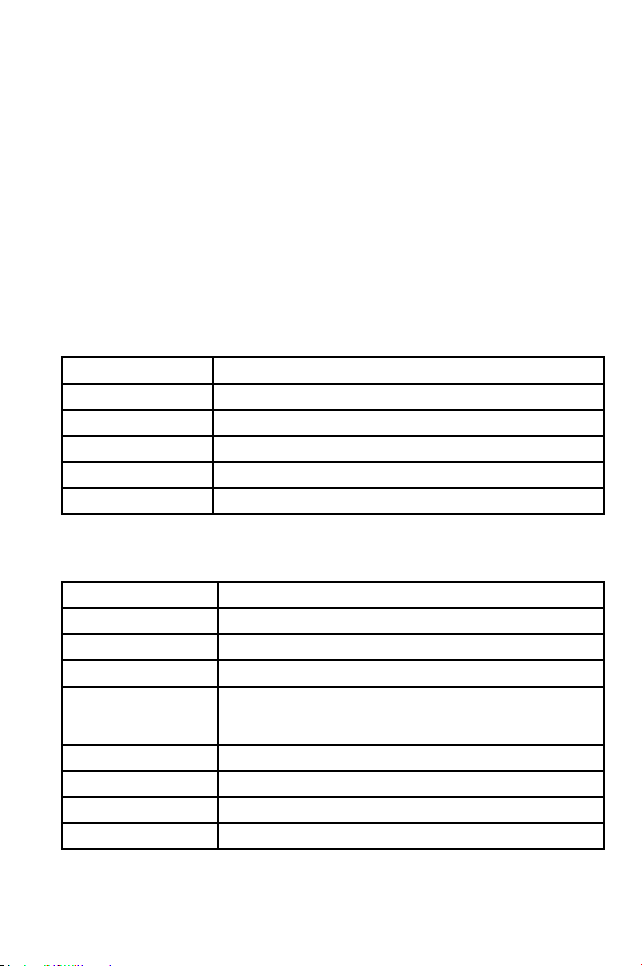
ELECTRICAL SPECIFICATIONS Accuracy at 23 °C ± 5 °C & < 75% R.H.
DC Voltage
Range Accuracy
400.0 mV ±( 0.3% rdg + 4 digits)
4.000, 40.00, 400.0 V ±( 0.5% rdg + 3 digits)
600 V ±( 1.0% rdg + 4 digits)
NMRR: >50 dB @ 50/60Hz
CMRR: >120 dB @ DC, 50/60 Hz, Rs=1 kΩ
Input Impedance: 10 MΩ, 30 pF nominal (1000 MΩ for 400.0 mV range)
Transient protection: 6.5 kV (1.2/50 μs surge)
AC Voltage (50Hz ~ 500Hz)
Range Accuracy
4.000, 40.00, 400.0 V ±( 1.5% rdg + 5 digits)
600 V ±( 2.0% rdg + 5 digits)
CMRR: >60dB @ DC to 60 Hz, Rs=1 kΩ
Maximum Crest Factor: < 1.75 : 1 at full scale & < 3.5 : 1 at half scale limited to
fundamental and harmonics, that fall within the meter
specied AC bandwidth for non-sinusoidal waveforms
Input Impedance: 10 MΩ, 30 pF nominal
Transient protection: 6.5 kV (1.2/50μs surge)
ACD-14 Plus: Average Sensing
ACD-14 TRMS Plus: True RMS sensing - 5% to100 % of range
Page 14
12
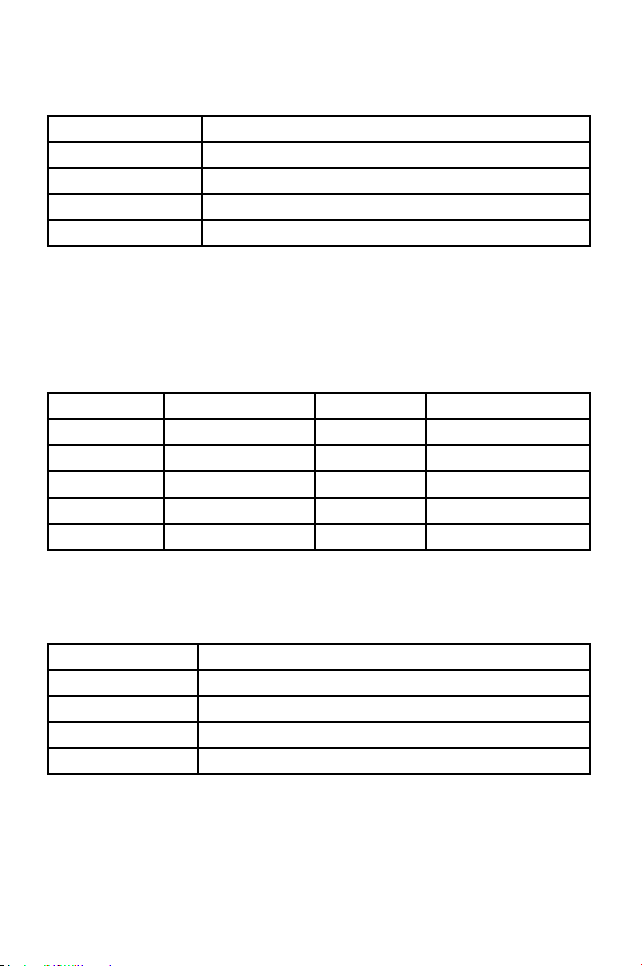
ACA Current (Clamp-on 50Hz / 60Hz)
Range Accuracy
1) 2) 3)
40.00, 400.0, 600 A ±( 1.5% rdg + 8 digits)
Overload Protections: ACA Clamp-on jaws: 600 A rms continuous
ACD-14 Plus: Average Sensing
ACD-14 TRMS Plus: True RMS sensing - 10 % to 100 % of range
1) Max Induced error from adjacent current carrying conductor: 0.05 A
2)
Specified accuracy
is from 1% rdg to 100% rdg of range and for measurements
made at the jaw center. When the conductor is not positioned at the jaw center,
position errors introduced are: Add 2% rdg to specified accuracy for measurements
made BEYOND jaw marking lines (toward jaw opening)
3)
Add 8
digits to specified accuracy @ reading < 10% rdg of range
Frequency
Function Sensitivity (Sine RMS) Range Accuracy
400.0 mVac 350mV 10 Hz ~ 2 kHz ±( 0.5% rdg + 4 digits)
4.000 Vac 1V 5 Hz ~ 5 kHz ±( 0.5% rdg + 4 digits)
4.000, 40.00 Vac 32V 5 Hz ~ 100 kHz ±( 0.5% rdg + 4 digits)
400.0 Vac 90V 5 Hz ~ 10 kHz ±( 0.5% rdg + 4 digits)
600 Vac 500V 5 Hz ~ 5 kHz ±( 0.5% rdg + 4 digits)
Display counts: 5000
Resolution: 0.001Hz
Transient protection : VAC input jacks : 6.5kV (1.2/50μs surge)
Ohms
Range Accuracy
400.0 Ω ±( 0.8% rdg + 8 digits)
4.000, 40.00, 400.0 kΩ ±( 0.6% rdg + 4 digits)
4.000 MΩ ±( 1.0% rdg + 4 digits)
40.00 MΩ ±( 2.0% rdg + 4 digits)
Open Circuit Voltage : 0.4 VDC typical
Transient protection : 6.5 kV (1.2/50μs surge)
Page 15
13
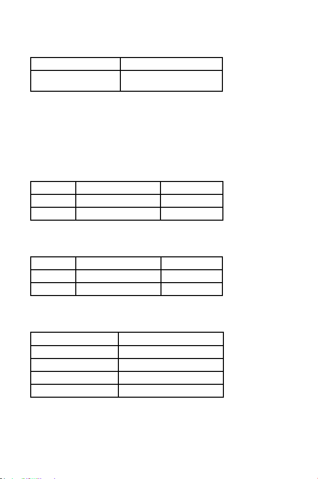
Capacitance
Range 1) Accuracy
2) 3)
500.0nF, 5.000μF, 50.00μF,
500.0μF, 3000μF
±( 3.5% rdg + 6 digits)
1)
Additional 50.00nF
range accuracy is not specified
2)
Accuracies with
film capacitor or better
3)
Specified with
battery voltage above 2.8V (approximately half full battery).
Accuracy decreases gradually to 12% rdg at low battery warning voltage of
approximately 2.4V
Transient protection: 6.5 kV (1.2/50 μs surge)
DC μA
Range Accuracy Burden Voltage
400.0μA ±( 2.0% rdg + 4 digits) 2.8mV/μA
2000μA ±( 1.2% rdg + 3 digits) 2.8mV/μA
Transient protection: 6.5 kV (1.2/50 μs surge)
AC μA (50Hz ~ 500Hz)
Range Accuracy Burden Voltage
400.0μA ±( 2.0% rdg + 5 digits) 2.8mV/μA
2000μA ±( 1.2% rdg + 5 digits) 2.8mV/μA
Transient protection: 6.5 kV (1.2/50 μs surge)
Type-K Temperature
Range Accuracy
-20 °C ~ 300 °C ±( 2% rdg + 3 °C)
301 °C ~ 537 °C ±( 3% rdg + 3 °C)
-4 °F ~ 572 °F ±( 2% rdg + 6 °F)
573 °F ~ 999 °F ±( 3% rdg + 6 °F)
Type-K thermocouple range & accuracy not included
Page 16

14
Audible Continuity Tester
Audible indication: between 10 Ω and 120 Ω.
Transient protection: 6.5 kV (1.2/50 μs surge)
Diode Tester / Open Circuit Voltage Test Current
(Typical) < 1.6 VDC @ 0.25 mA
Transient protection: 6.5 kV (1.2/50 μs surge)
Max Hold* (where applicable)
Specied accuracy ± 50 digits for changes > 25 ms in duration
Page 17
15
MAX 600A
MAX
HOLD
ON
OFF
SELECT
MAX
COM
A
Hz
ACD-14 PLUS
!
!
A
600V CAT III
℉
Black
Red
SELECT
Measuring
DC Voltage
Figure 1
Page 18
16
MAX 600A
MAX
HOLD
ON
OFF
SELECT
MAX
COM
A
Hz
ACD-14 PLUS
!
!
A
600V CAT III
℉
SELECT
Black
Red
Measuring
AC Voltage
Figure 2
Page 19
17
MAX 600A
MAX
HOLD
ON
OFF
SELECT
MAX
COM
A
Hz
ACD-14 PLUS
!
!
A
600V CAT III
Hz
℉
Black
Red
A
Hz
Measuring
AC Current
and Frequency
Figure 3
Page 20
18
MAX 600A
MAX
HOLD
ON
OFF
SELECT
MAX
COM
A
Hz
ACD-14 PLUS
!
!
A
600V CAT III
℉
Black
Red
Measuring
Resistance
Figure 4
Page 21
19
MAX 600A
MAX
HOLD
ON
OFF
SELECT
MAX
COM
A
Hz
ACD-14 PLUS
!
!
A
600V CAT III
℉
Black
Red
SELECT
Continuity
Testing
Figure 5
Page 22
20
MAX 600A
MAX
HOLD
ON
OFF
SELECT
MAX
COM
A
Hz
ACD-14 PLUS
!
!
A
600V CAT III
℉
Black
Red
SELECT
Testing Diodes
Figure 6
Page 23
21
MAX 600A
MAX
HOLD
ON
OFF
SELECT
MAX
COM
A
Hz
ACD-14 PLUS
!
!
A
600V CAT III
℉
Black
+-
Red
SELECT
Measuring
Capacitance
Figure 7
Page 24
22
MAX 600A
MAX
HOLD
ON
OFF
SELECT
MAX
COM
A
Hz
ACD-14 PLUS
!
!
A
600V CAT III
℉
+
-
Measuring
Temperature
Figure 8
Page 25
23
MAX 600A
MAX
HOLD
ON
OFF
SELECT
MAX
COM
A
Hz
ACD-14 PLUS
!
!
A
600V CAT III
℉
Black
X
Red
Measuring
μA Current
Figure 9
 Loading...