

Page 1
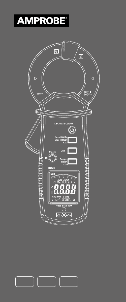
ALC-110
Leakage Current
Clamp
User Manual
ENG FRE
SPA
Page 2

Page 3

ALC-110
Leakage Current
Clamp
User Manual
English
11/2018, 6011518 A
©2018 Amprobe
All rights reserved. Printed in Taiwan
Page 4

Limited Warranty and Limitation of Liability
Your Amprobe product will be free from defects in material and
workmanship for one year from the date of purchase unless local
laws require otherwise. This warranty does not cover fuses, disposable
batteries or damage from accident, neglect, misuse, alteration,
contamination, or abnormal conditions of operation or handling.
Resellers are not authorized to extend any other warranty on the
behalf of Amprobe. To obtain service during the warranty period,
return the product with proof of purchase to an authorized Amprobe
Service Center or to an Amprobe dealer or distributor. See Repair
Section for details. THIS WARRANTY IS YOUR ONLY REMEDY. ALL
OTHER WARRANTIES - WHETHER EXPRESS, IMPLIED OR STATUTORY
- INCLUDING IMPLIED WARRANTIES OF FITNESS FOR A PARTICULAR
PURPOSE OR MERCHANTABILITY, ARE HEREBY DISCLAIMED.
MANUFACTURER SHALL NOT BE LIABLE FOR ANY SPECIAL, INDIRECT,
INCIDENTAL OR CONSEQUENTIAL DAMAGES OR LOSSES, ARISING FROM
ANY CAUSE OR THEORY. Since some states or countries do not allow
the exclusion or limitation of an implied warranty or of incidental or
consequential damages, this limitation of liability may not apply to you.
Repair
All Amprobe returned for warranty or non-warranty repair or
for calibration should be accompanied by the following: your
name, company’s name, address, telephone number, and proof of
purchase. Additionally, please include a brief description of the
problem or the service requested and include the test leads with
the meter. Non-warranty repair or replacement charges should be
remitted in the form of a check, a money order, credit card with
expiration date, or a purchase order made payable to Amprobe.
In-warranty Repairs and Replacement – All Countries
Please read the warranty statement and check your battery before
requesting repair. During the warranty period, any defective test tool
can be returned to your Amprobe distributor for an exchange for the
same or like product. Please check the “Where to Buy” section on
amprobe.com for a list of distributors near you. Additionally, in the
United States and Canada, in-warranty repair and replacement units
can also be sent to an Amprobe Service Center (see address below).
Non-warranty Repairs and Replacement – United States and Canada
Non-warranty repairs in the United States and Canada should be
sent to an Amprobe Service Center. Call Amprobe or inquire at your
point of purchase for current repair and replacement rates.
USA: Canada:
Amprobe Amprobe
Everett, WA 98203 Mississauga, ON L4Z 1X9
Tel: 877-AMPROBE (267-7623) Tel: 905-890-7600
Non-warranty Repairs and Replacement – Europe
European non-warranty units can be replaced by your BehaAmprobe distributor for a nominal charge. Please check the “Where
to Buy” section on beha-amprobe.com for a list of distributors near
you.
Beha-Amprobe
Division and reg. trademark of Fluke Corp. (USA)
Germany* United Kingdom
In den Engematten 14 52 Hurricane Way
79286 Glottertal Norwich, Norfolk
Germany NR6 6JB United Kingdom
Phone: +49 (0) 7684 8009 - 0 Phone: +44 (0) 1603 25 6662
beha-amprobe.de beha-amprobe.com
The Netherlands - Headquarters**
Science Park Eindhoven 5110
5692 EC Son
The Netherlands
Phone: +31 (0) 40 267 51 00
beha-amprobe.com
*(Correspondence only – no repair or replacement available from
this address. European customers please contact your distributor.)
**single contact address in EEA Fluke Europe BV
Page 5

Leakage Current Clamp
CONTENTS
SYMBOLS ............................................................... 2
SAFETY INFORMATION .........................................2
UNPACKING AND INSPECTION .............................4
FEATURES AND APPLICATIONS ............................. 4
DESCRIPTION OF THE INSTRUMENT ..................... 5
DESCRIPTION OF THE LCD .................................... 5
POWER ON/OFF ..................................................... 6
AUTO BACKLIGHT ................................................. 6
AC CURRENT MEASUREMENT .............................. 7
LEAKAGE CURRENT MEASUREMENT ................... 8
DATA HOLD........................................................... 10
MAX HOLD ........................................................... 10
LOW PASS FILTER (50-60 HZ)
& APPLIANCE FILTER ............................................. 11
SPECIFICATIONS ....................................................13
ELECTRICAL SPECIFICATIONS ...............................15
MAINTENANCE ..................................................... 17
BATTERY REPLACEMENT ...................................... 17
1
Page 6
SYMBOLS
�
CAT III
B
> 30 A/m
Caution
WARNING. HAZARDOUS VOLTAGE
Risk of electric shock
Consult user documentation
Application around and removal from
uninsulated hazardous live conductors is
permitted
Measurement Category III is applicable to
test and measuring circuits connected to
the distribution part of the building’s
low-voltage MAINS installation
Alternating current
Do not operate within external low
frequency magnetic fields >30 A/m
Equipment protected throughout by
DOUBLE INSULATION or REINFORCED
INSULATION
Battery
Conforms to European Union directives
Certified by CSA Group to North American
safety standards
Conforms to relevant Australian EMC
standards
This product complies with the WEEE
Directive marking requirements. The
affixed label indicates that you must not
discard this electrical/electronic product
in domestic household waste. Product
Category: With reference to the equipment
types in the WEEE Directive Annex I,
this product is classed as category 9
“Monitoring and Control Instrumentation”
product. Do not dispose of this product as
unsorted municipal waste.
SAFETY INFORMATION
The meter complies with:
• IEC/EN 61010-1 3rd Ed., UL61010-1 3rd Ed. and CAN/
CSA C22.2 No. 61010-1-12 to CAT III 600 V, pollution
degree 2.
• IEC/EN 61010-2-032
• IEC/EN 61557-13
• EMC IEC/EN 61326-1 and IEC/EN 61326-2-2
Measurement Category III (CAT III) is for measurements
performed in a building installation. Examples include
measurements on distribution boards, circuit breakers
and wiring — including cables, bus-bars, junction boxes,
switches, socket-outlets in a fixed installation — as well as
equipment for industrial use and stationary motors with a
permanent connection to the fixed installation.
2
Page 7

CENELEC Directives
The instrument conforms to CENELEC Low-voltage
directive 2014/35/EU and Electromagnetic compatibility
directive 2014/30/EU
Warning
To prevent possible electrical shock, fire, or personal injury:
• Read all safety information before you use the Product.
• Carefully read all instructions.
• Use the Product only as specified, or the protection
supplied by the Product can be compromised.
• Do not use the Product around explosive gas, vapor, or
in damp or wet environments.
• Do not touch voltages >30 V AC rms, 42 V AC peak,
or 60 V DC.
• Before each use, examine the Product. Look for cracks
or missing pieces of the Product housing. Also look for
loose or weakened components. Carefully examine the
insulation around the jaws.
• Do not use the Product if it is damaged.
• Limit operation to the specified measurement category,
voltage, or amperage ratings.
• Use extreme caution when working around bare
conductors or busbars. Contact with the conductor could
result in electric shock.
• Do not hold the Product anywhere beyond the tactile barrier.
• When measuring current, center the conductor in the clamp.
• Remove the batteries if the Product is not used for an
extended period of time, or if stored in temperatures
above 140 °F (60 °C). If the batteries are not removed,
battery leakage can damage the Product.
• Replace the batteries when the low battery indicator
shows to prevent incorrect measurements.
• Use only 1.5V AAA batteries, properly installed in the
Product case, to power the Product.
• Use only 1.5V AAA alkaline batteries and follow all
battery care from the manufacturer.
• Never remove the battery cover or open the case of
the Product without first removing the jaws from a live
conductor.
• The battery door must be closed and locked before you
operate the Product.
• Do not leave the Product on or near objects of high
temperature.
• For use by competent persons only.
• For safe operation of the Product, do not operate within
external low frequency magnetic fields >30 A/m. Ensure
the jaw is locked before making measurements.
• Have an approved technician repair the Product.
Caution
• For best accuracy please consider following impacts:
- use whenever possible optimized position of the
clamp when the conductor is positioned is in the center
of jaw and the angle between conductor and jaw is 90°
- reduce influences by external magnetic field
(for impact see error E11 in specification table)
- reduce influences by contamination of the jaw
(recommendation for cleaning see in chapter
maintenance)
• The measurement of differential current will be
influenced by the load current (for influence of load
current, see error E12 in Specification table).
3
Page 8

• If the Product is used in the vicinity of equipment that
generates electromagnetic interference, the display
may become unstable or the measurements shown may
be subject to large errors.
• Do not subject the jaw to unreasonably strong shock,
vibration or force.
• If dust gets into the top of the jaw, remove it
immediately. Do not close the jaw when dust is trapped
in its joints as the sensor may be damaged.
UNPACKING AND INSPECTION
Your package should include:
1 ALC-110 Leakage Current Clamp
2 1.5 V AAA batteries
1 User manual
1 Soft carrying case
If any of the items are damaged or missing, return the
complete package to the place of purchase for an exchange.
Note: Batteries do not come installed. Please refer to the
Battery Replacement section for further instructions.
FEATURES AND APPLICATIONS
Features
• CAT III 600 V safety rated
• Leakage clamp acc. IEC/EN61557-13, VDE 0413-13
• Low influence of external low frequency magnetic
fields @ I
operating class 2, ≤ 30A/m
• True-rms measurements for best accuracy when
measuring complex, non-sinusoidal waveforms
• Highest resolution of 0.001 mA, measure up to 60 A:
Range: 6 mA, resolution of 0.001 mA
Range: 60 mA, resolution of 0.01 m
Range: 600 mA, resolution of 0.1 mA
Range: 6 A, resolution of 0.001 A
Range: 60 A, resolution of 0.01 A
• Selectable limits: 3.5 mA, 10 mA, 12 mA, 0.25 mA, 0.5 mA
• Selectable filter function to remove unwanted noise:
- appliance filter (acc. IEC/EN 61557-16),
- 50/60 Hz filter
- no filter
• Frequency range 15 Hz to 1 kHz to cover railway and
industrial application
• Max and data hold
• Mechanical jaw lock
• 1.2 in (30 mm) jaw opening
• Auto backlight
• Auto power off
Applications
• Measurement of earth leakage current.
• Measurement of differential leakage currents.
• Measuring leakage current through the earth (PE)
conductor.
• Tracing the source of earth leakage current.
• Measurement of current consumption of appliances in
service or customer service sector without interruption
to the circuit.
3.5 mA … 600 mA / 40 Hz to 1 kHz:
N
4
Page 9
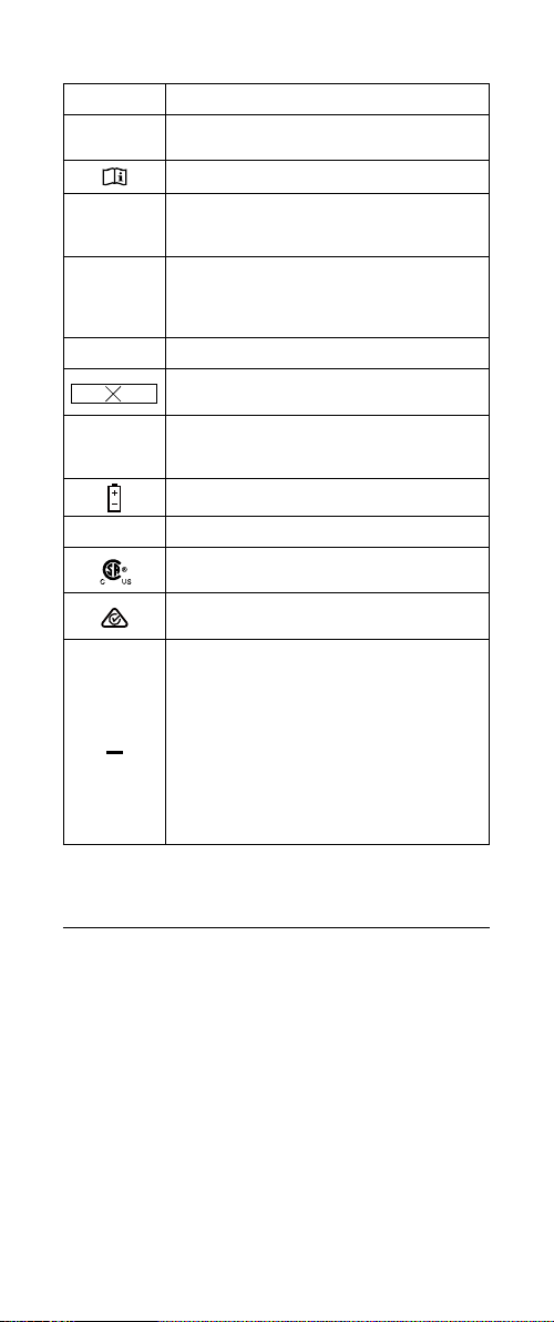
DESCRIPTION OF THE INSTRUMENT
1
2
3
4
5
6
7
8
9
1
Jaw
2
Hand barrier
3
Jaw unlock
4
LCD
5
Auto backlight sensor
6
Power
DESCRIPTION OF THE LCD
1
2
3
4
5
1
Auto power off
2
Data/Max hold
3
Warning & caution
4
Low battery
5
6
7
7
Data HOLD
(for Max HOLD press for
>2 sec)
8
Limit
9
Range
(for Filter press for >2 sec)
6
7
Limit function
Bar graph
Appliance filter / 50-60 Hz filter
5
Page 10
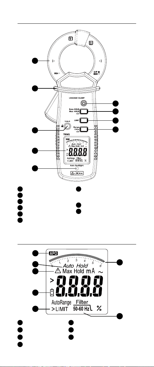
POWER ON/OFF
Press > 1 sec
Press > 1 sec
The meter will display battery capacity when powering up.
Please replace the battery when less than 10% is shown.
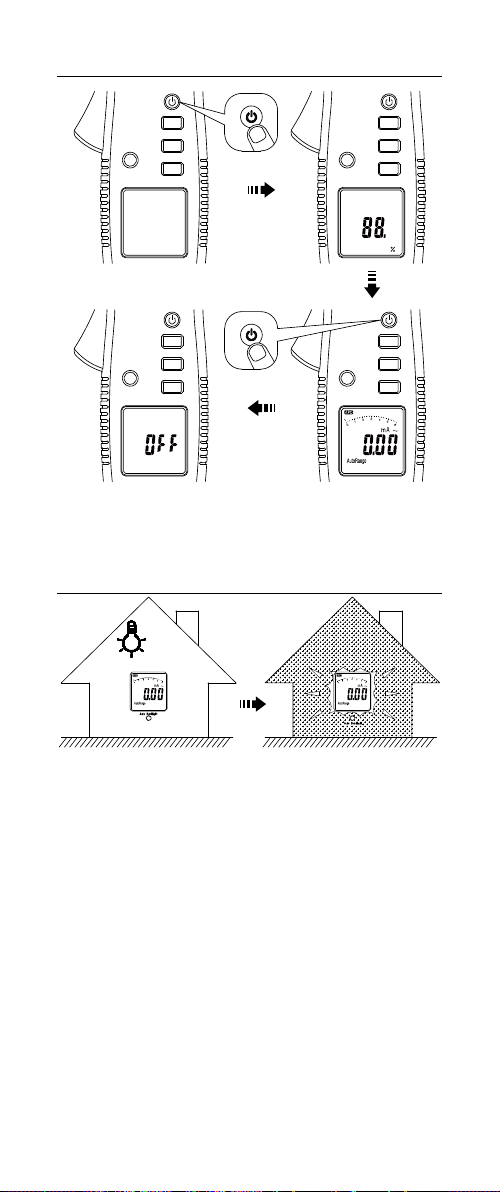
AUTO BACKLIGHT
6
Page 11
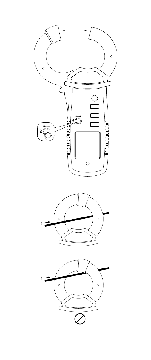
AC CURRENT MEASUREMENT
1.2 in
(30 mm)
Hold to unlock
Position Error
OK
OK
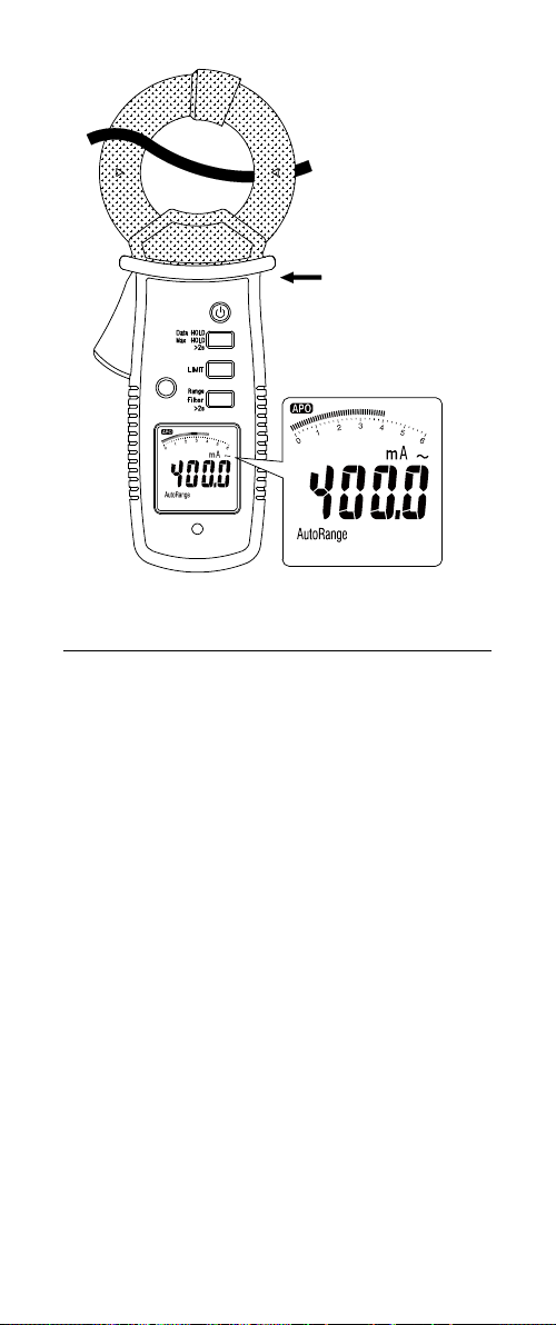
When measuring current, ensure the cable is located in the
center of the clamp to avoid position errors.
7
Page 12
CAT III 600V
with respect to
earth for the jaw.
Hand Guard Barrier
Do not hold the
meter above the
Barrier
LEAKAGE CURRENT MEASUREMENT
The leakage current flows when an unintentional electrical
connection occurs between an energized part of the
electrical system and the earth/ground. The desired value of
leakage current should be 0 A. Check applicable regulations
and standards for allowable limits of leakage current.
For properly grounded systems, in case of the fault,
leakage current should be conducted via earth conductor
(PE) (Figure 1). We can measure such current directly in a
earth conductor using a leakage clamp meter.
In some cases, specifically when equipment is not properly
grounded, the leakage current may flow through other
paths. Use differential current measurement methods
to verify such current leaks (Figure 2, Figure 3, Figure 4).
Clamp a leakage current meter around all active conductors
(hot and neutrals), but without any earth conductor. An
electromagnetic field around all conductors should cancel
each other if there is no current leak and clamp meter
should read 0A. If there is a leak, there will be imbalance
between electromagnetic fields, and the clamp meter will
read the actual value of that leakage current.
Leakage current measurement process
1. Turn the meter on.
2. Make sure the jaw is closed and the meter is away from
conductors and other sources of electromagnetic fields.
3. Clamp the meter around a earth conductor. The meter
will indicate leakage current in earth conductor.
4. Clamp the meter around all active conductors, hot and
neutrals (but without earth conductors). The meter
will indicate total system leakage current that consists
of earth conductor current as well as any other stray
current leakage.
8
Page 13
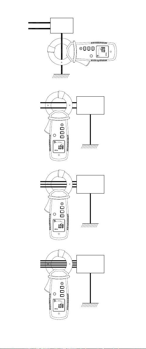
Load
Figure 1: Direct Method
Measurement of earth (PE) leakage current
Load
1ø2W
Figure 2
Load
3ø3W
Figure 3
Load
3ø4W
Figure 2, 3 and 4: Differential Method
Measurement of differential leakage current
Figure 4
9
Page 14
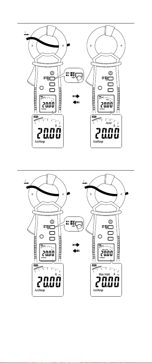
DATA HOLD
MAX HOLD
20A 0A
Press
Press > 2 sec
10
Page 15
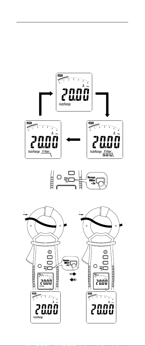
LOW PASS FILTER (50-60 HZ) & APPLIANCE FILTER
Low Pass and Appliance filters are used to filter out high
frequency noise that affect precise measurement of the meter.
• Use Low Pass 50/60Hz filter to perform measurements on
equipment driven by Variable Frequency Drives (VFDs) or
affected by high frequency noise. Significant difference
in reading between measurement with and without low
pass filter may indicate presence of harmonics.
• Use Appliance Filter to conduct leakage current
measurements of appliances in accordance with
IEC/EN 61557-16 regulation requirements.
Wide Mode
Appliance Filter 50-60 Hz
Auto/ Manual Range
20A
Auto Range Manual Range
20A
11
Page 16
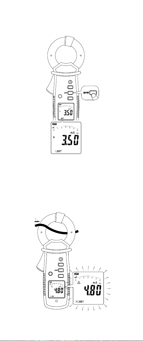
LIMIT
Limit selection:
The LIMIT function offers 5 limit values (3.5 mA / 10 mA / 12 mA /
0.25 mA / 0.5 mA) in accordance with safety standards.
1. Continue pressing LIMIT button until desired limit value
is selected. The unit will be looping between 3.5 mA /
10 mA / 12 mA / 0.25 mA / 0.5 mA values.
2. When desired value is selected wait 2 sec to automatically
apply selection. The LIMIT symbol will be displayed on the
LCD to indicate that the function is active.
3. Verify the selection by pressing the LIMIT button one
time. The unit will display the selected value for 2 seconds.
4. To disable the LIMIT function, press the LIMIT button for
>2 sec.
Display when limit is exceeded:
The internal buzzer will continue beeping and the
display will flash and show a warning symbol when the
measurements exceeds the selected limit value.
12
Page 17
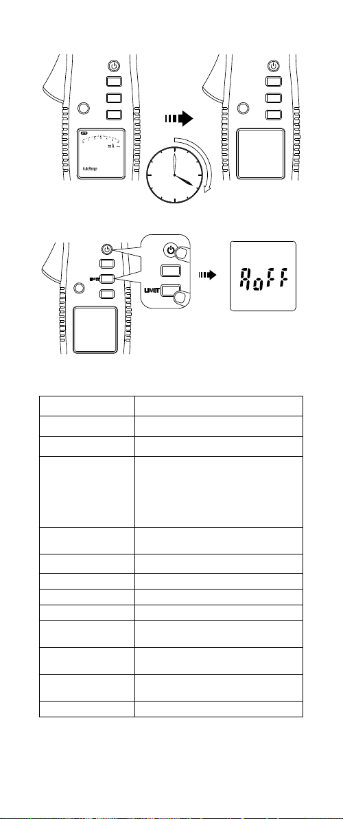
Auto Power Off
20 min
Disable Auto Power Off
Hold LIMIT
Button down
and power up
SPECIFICATIONS
Display 6000 counts digit large scale
Sensing True RMS
Update rate 5 per second nominal
32 °F to 86 °F (0 °C to 30 °C)
Operating
temperature and
relative humidity
Storage
temperature
Jaw opening 1.2 in (30 mm) max.
Pollution degree 2
IP rating IP20
Operating altitude ≤ 2000 m
Overload
protection
Measurement
category
Safety compliance
E.M.C. Meets EN61326-1
(≤ 80% R.H.)
86 °F to 104 °F (30 °C to 40 °C)
(≤ 75% R.H.)
104 °F to 122 °F (40 °C to 50 °C)
(≤ 45% R.H.)
-4 °F to 140 °F (-20 °C to 60 °C)
(with battery removed)
600 V rms
CAT III 600 V
IEC 61010-1, IEC 61010-2-032,
IEC 61557-13
13
Page 18

Korea (KCC): Class A equipment
(Industrial Broadcast &
Communications Equipment)
Electromagnetic
Compatibility
Class A: Equipment meets
requirements for industrial
electromagnetic wave equipment and
the seller or user should take notice
of it. This equipment is intended for
use in business environments and not
to be used in homes.
Current sensor
operating class
Selectable limits
Selectable filter
functions
AC frequency
response
Class 2, ≤30 A/m acc. IEC/EN 61557-13
@ I
N: 3.500 mA – 600.0 mA / 40 Hz to
1 kHz
0.250 mA / 0.500 mA / 3.500 mA /
10.00 mA / 12.00 mA
Appliance filter
(acc. IEC/EN 61557-16),
50/60 Hz filter or no filter
15 Hz ... 1 kHz
@ 30 A/m:
reading 3.5...10 mA <20%
reading >10 mA <12.5%
Operating
uncertainty (B)
@ 10 A/m:
reading 3.5...10 mA <15%
reading >10 mA <10%
(valid for proper range with best
resolution)
Intrinsic
uncertainty (A)
See ELECTRICAL SPECIFICATIONS
Position error (E1) Add ±1% of reading
Supply voltage
error (E2)
Influence of
temperature (E3)
N/A
Add 0.1 x (Specified accuracy) / °C,
< 21 °C, > 25 °C
Influence of
interference
N/A
voltages (E4)
Influence of
earth electrode
N/A
resistance (E5)
Influence for
phase angle of
impedance of
N/A
circuit under test
(E6)
Influence of
system frequency
N/A
(E7)
Influence of
system voltage
N/A
(E8)
Influence
of distorted
<(1%+20d)
waveform (E9)
Influence of
system d.c.
N/A
quantities (E10)
14
Page 19

Influence of
external low
frequency
magnetic fields
(E11)
Influence of load
current (E12)
10 A/m: add ±0.1 mA
30 A/m: add ±0.3 mA
@ I
: 3.500 mA – 600.0 mA / 40 Hz
N
to 1 kHz
and a frequency of the magnetic
field of 15 to 400 Hz acc. to
IEC 61000-4-8
Add ±6 μA per A load current
Influence of touch
current caused
common mode
N/A
voltage (E13)
Influence of
frequency (E14)
Influence of
repeatability (E15)
Agency approval
N/A
N/A
Power supply Two 1.5 V AAA (LR03) batteries
Battery life 60 hours typical
Low battery
voltage
Low battery
indication
Approx. 2.5 V
Auto power off Idle for 20 minutes
Dimensions
(H x W x L)
Weight
8.7 x 3.5x 1.8 in
(221 x 89 x 48 mm)
Approximately 0.90 lb (410 g) with
battery installed
ELECTRICAL SPECIFICATIONS
Accuracy is given as ± (% of reading + counts of least
significant digit) at 23 °C ± 2 °C (≤ 80% R.H.)
AC Function
• AC A specifications are AC coupled, true RMS.
• For non-sinusoidal waveforms, Additional Accuracy by
Crest Factor (C.F.):
Add 1.0% for C.F. 1.0 to 2.0
Add 2.5% for C.F. 2.0 to 2.5
Add 4.0% for C.F. 2.5 to 3.0
• Max. Crest Factor of Input Signal:
3.0 @ 3000 counts
2.0 @ 4500 counts
1.5 @ 6000 counts
• Frequency Response is specified for sine waveform.
• When operating under magnetic field add error E11.
• When measuring leakage current of multiple conductors,
add error E12 for influence of load current.
• For Position Error see error E1.
15
Page 20

AC Current
Range
15 to 40 Hz 40 to 50 Hz 50 to 60 Hz 60 to 1 kHz
[1]
6 mA
±(5.0%+5D) ±(2.0%+5D) ±(1.0%+5D) ±(2.0%+5D)
60 mA
±(5.0%+5D) ±(2.0%+5D) ±(1.0%+5D) ±(2.0%+5D)
600 mA
±(5.0%+5D) ±(2.0%+5D) ±(1.0%+5D) ±(2.0%+5D)
6 A
60 A
[1]
Minimum Reading is 0.010 mA
[2]
Frequency response is 60 Hz to 10 kHz.
- ±(2.0%+5D) ±(1.0%+5D) ±(2.0%+5D)
- ±(2.0%+5D) ±(1.0%+5D) ±(2.0%+5D)
Accuracy
When frequency > 1 kHz, add 0.5% to accuracy.
Minimum Resolution: 0.001 mA
Low Pass Filter (50–60 Hz Filter)
Range
6 mA
[1]
Accuracy
50 to 60 Hz
±(1.0%+5D)
60 mA ±(1.0%+5D)
600 mA ±(1.0%+5D)
6 A ±(1.0%+5D)
60 A ±(1.0%+5D)
[1]
Minimum Reading is 0.010 mA
Minimum Resolution: 0.001 mA
Cut-off frequency: 200 Hz
Appliance Filter (acc. IEC/EN 61557-16)
Range
6 mA
[1]
±(1.0%+5D) ±(2.5%+5D)
50 to 60 Hz 60 to 200 Hz
Accuracy
60 mA ±(1.0%+5D) ±(2.5%+5D)
600 mA ±(1.0%+5D) ±(2.5%+5D)
6 A ±(1.0%+5D) ±(2.5%+5D)
60 A ±(1.0%+5D) ±(2.5%+5D)
[1]
Minimum Reading is 0.010 mA
Minimum Resolution: 0.001 mA
Cut-off frequency: 1 kHz
[2]
[2]
[2]
16
Page 21

MAINTENANCE
Do not attempt to repair this meter. It contains no
user-serviceable parts. Repair or serving should only be
performed by qualified personnel.
1. Inspect the jaw mating surface for cleanliness. If any
foreign material is present, the jaw will not close properly
and measurement errors will result.
2. Verify that the range on the meter is correct.
Calibration Interval
We suggest a calibration interval of one year. If the instrument is
rarely used, the calibration interval can be extended to 3 years.
Cleaning
To avoid damaging the meter, do not use abrasives or
solvents to clean it.
Always keep the metal parts of the jaw clean and dry. Avoid
allowing dust or other particles to come in-between the jaws.
Remove and clean these parts carefully by soft air pressure.
Also ensure that there is no rust or oxidation on the metal
surfaces. In case of contamination (dust or oxidation) the
commutator segments of the jaw could be damaged or
bent. In this case, the current clamp will be damaged and
outside specification. Please send the current clamp to
service for repair.
BATTERY REPLACEMENT
1. Disconnect the jaw from measuring circuit.
2. Turn the meter OFF.
3. Remove the screws from the battery cover and open the
battery cover.
4. Remove the batteries and replace with 2 1.5 V AAA
size (IEC R03) batteries. Observe correct polarity when
installing the batteries.
5. Replace the battery cover and re-fasten the screw.
17
Page 22

Page 23

ALC-110
Pince de mesure de
courant de fuite
Manuel de
l’utilisateur
Français
11/2018, 6011518 A
©2018 Amprobe
Tous droits réservés. Imprimé à Taïwan
Page 24

Garantie limitée et limitation de responsabilité
Votre produit Amprobe sera exempt de défauts de matériaux et de
fabrication pendant un (1) an à compter de la date d'achat, sauf
exigence contraire en vertu de la juridiction locale. Cette garantie
ne s'applique pas aux fusibles, aux piles jetables ou endommagées
par accident, à la négligence, à la mauvaise utilisation, à l'altération,
à la contamination ou aux conditions anormales d'utilisation ou
de manipulation. Les revendeurs ne sont pas autorisés à prolonger
toute autre garantie au nom de Amprobe. Pour une réparation
au cours de la période de garantie, retournez le produit avec la
preuve d'achat à un centre de service autorisé par Amprobe ou à un
revendeur ou un distributeur Amprobe. Voir la section Réparation
pour plus de détails. CETTE GARANTIE EST VOTRE SEUL RECOURS.
TOUTES LES AUTRES GARANTIES – QU'ELLES SOIENT EXPLICITES,
IMPLICITES OU JURIDIQUES – Y COMPRIS LES GARANTIES IMPLICITES
D'ADAPTATION À UN USAGE PARTICULIER OU MARCHAND,
SONT EXCLUES. LE FABRICANT NE SERA PAS RESPONSABLE DES
DOMMAGES SPECIAUX, INDIRECTS, ACCESSOIRES OU CONSECUTIFS
PROVENANT DE TOUTE CAUSE OU THEORIE. Etant donné que
certains pays ou états n'autorisent pas l'exclusion ou la limitation
des garanties implicites ou des dommages directs ou indirects, cette
limitation de responsabilité peut ne pas s'appliquer à vous.
Réparation
Tout produit Amprobe retourné pour réparation sous garantie
ou hors garantie ou pour l'étalonnage doit être accompagné des
documents suivants:votre nom, le nom de votre société, votre
adresse, votre numéro de téléphone et la preuve d'achat. De plus,
veuillez inclure une brève description du problème ou du service
demandé et incluez les cordons de mesure avec le compteur. Les
frais de réparation ou de remplacement non garantis doivent être
réglés sous forme de chèque, mandat, carte de crédit avec date
d'expiration ou bon de commande payable à Amprobe.
Réparations et remplacement couverts par la garantie – Tous les
pays
Veuillez lire la déclaration de garantie et vérifier la pile avant de
demander une réparation. Pendant la période de garantie, tout outil
de vérification défectueux peut être retourné à votre distributeur
Amprobe pour un échange de produit identique ou similaire.
Veuillez consulter la section «Où acheter» sur le site amprobe.
com pour obtenir une liste des distributeurs près de chez vous. En
outre, aux États-Unis et au Canada, les réparations sous garantie et
les unités de remplacement peuvent également être envoyés à un
centre de service Amprobe (voir adresse ci-dessous).
Réparation et remplacement non couverts par la garantie – ÉtatsUnis et Canada
Pour les réparations non couvertes par la garantie aux États-Unis
et au Canada, l'appareil doit être envoyé à un centre de service
Amprobe. Appelez Amprobe ou renseignez-vous auprès de votre
point de vente pour les tarifs de réparation et de remplacement
actuels.
États-Unis: Canada:
Amprobe Amprobe
Everett, WA 98203 Mississauga, ONL4Z 1X9
Tél: 877-AMPROBE (267-7623) Tél: 905-890-7600
Réparation et remplacement non couverts par la garantie – Europe
Les unités hors garantie européenne peuvent être remplacées
par votre distributeur Amprobe/Beha-Amprobe pour une somme
modique. Veuillez consulter la section «Où acheter» sur le site
beha-amprobe.com pour obtenir une liste des distributeurs près de
chez vous.
Beha-Amprobe
Division et marque déposée de Fluke Corp. (USA)
Allemagne* Royaume-Uni
In den Engematten 14 52 Hurricane Way
79286 Glottertal Norwich, Norfolk
Allemagne NR6 6JB Royaume-Uni
Téléphone : +49 (0) 7684 8009 - 0 Téléphone : +44 (0) 1603 25 6662
beha-amprobe.de beha-amprobe.com
Pays-Bas - Siège social**
Science Park Eindhoven 5110
5692 EC Son
Pays-Bas
Téléphone : +31 (0) 40 267 51 00
beha-amprobe.com
*(Correspondance uniquement: aucune réparation ou remplacement à cette adresse. Clients européens, veuillez contacter votre
distributeur.)
**adresse de contact unique dans l'EEE Fluke Europe BV
Page 25

Pince de mesure de courant de fuite
TABLE DES MATIÈRES
SYMBOLES ............................................................. 2
CONSIGNES DE SÉCURITÉ ..................................... 2
DÉBALLAGE ET INSPECTION ................................. 4
FONCTIONS ET APPLICATIONS .............................4
DESCRIPTION DE L'INSTRUMENT ......................... 5
DESCRIPTION DE L'ÉCRAN LCD ............................. 5
MISE SOUS TENSION/HORS TENSION .................. 6
RÉTROÉCLAIRAGE AUTOMATIQUE ......................6
MESURE DU COURANT CA ................................... 7
MESURE DU COURANT DE FUITE ......................... 8
CONSERVATION DES DONNÉES ...........................10
CONSERVATION DU MAXIMUM ..........................10
FILTRE PASSE-BAS (50-60 HZ) ET FILTRE POUR
APPAREILS ............................................................. 11
SPÉCIFICATIONS ÉLECTRIQUES ............................15
MAINTENANCE ..................................................... 17
REMPLACEMENT DES PILES ................................. 17
1
Page 26

SYMBOLES
�
CAT III
B
> 30 A/m
Attention
AVERTISSEMENT. TENSION DANGEREUSE
Risque de décharge électrique
Consultez la documentation utilisateur
L'application à proximité et le retrait de
conducteurs sous tension dangereux non
isolés sont autorisés.
La catégorie de mesure III est applicable
aux circuits de tests et de mesures
connectés à la partie distribution de
l'installation SECTEUR basse tension des
bâtiments.
Courant alternatif
Ne l'utilisez pas à proximité de champs
magnétiques externes à basse fréquence
>30 A/m
Équipement protégé par une DOUBLE
ISOLATION ou une ISOLATION RENFORCÉE
Pile
Conforme aux directives de l'Union
européenne
Certifié par le Groupe CSA selon les
normes de sécurité d'Amérique du Nord
Conforme aux normes relatives aux CEM
applicables en Australie
Ce produit est conforme aux exigences
de marquage de la directive DEEE.
L'étiquette apposée indique que vous
ne devez pas jeter ce produit électrique/
électronique avec les déchets ménagers.
Catégorie du produit: Concernant les
types d'équipements de l'Annexe I de la
Directive DEEE, ce produit est classifié
en tant que produit de catégorie 9
«Instrumentation de surveillance et de
contrôle». Ne jetez pas ce produit avec les
déchets municipaux non triés.
CONSIGNES DE SÉCURITÉ
L'appareil de mesure est conforme à:
• IEC/EN 61010-1 3e Éd., UL61010-1 3e Éd. et CAN/
CSA C22.2 No. 61010-1-12 à CAT III 600 V, degré de
pollution 2
• IEC/EN 61010-2-032
• IEC/EN 61557-13
• CEM IEC/EN 61326-1 et IEC/EN 61326-2-2
La catégorie de mesure III (CAT III) est destinée aux
mesures effectuées sur l'installation des bâtiments. Les
exemples comprennent les mesures de tableaux de
distribution, disjoncteurs et câblages, y compris les câbles,
barres omnibus, boîtiers de jonction, commutateurs, prises
dans une installation fixe ainsi que les équipements pour
une utilisation industrielle et les moteurs stationnaires
avec une connexion permanente à l'installation fixe.
2
Page 27

Directives CENELEC
L'instrument est conforme à la directive Basse tension
CENELEC 2014/35/UE et à la directive Compatibilité
électromagnétique 2014/30/UE.
Avertissement
Pour éviter tout risque d'électrocution, de brûlure ou de
blessure:
• Lisez toutes les informations de sécurité avant
d'utiliser le Produit.
• Lisez attentivement toutes les instructions.
• Utilisez le Produit uniquement comme indiqué, ou
la protection fournie par le Produit pourrait être
compromise.
• N'utilisez pas la Produit près de vapeurs et de gaz
explosifs ou dans des environnements humides.
• Ne touchez pas des tensions > 30 V CA RMS, 42 V CA
crête ou 60 V CC.
• Avant chaque utilisation, examinez le Produit.
Recherchez les fissures ou les éléments manquants
du boîtier du Produit. Recherchez également
les composants desserrés ou fragilisés. Examinez
attentivement l'isolation autour des mâchoires.
• N'utilisez pas le Produit s'il est endommagé.
• Limitez l'utilisation aux catégories de mesure, tensions
ou ampérages nominaux spécifiés.
• Faites preuve d'une grande prudence lorsque vous
travaillez à proximité de conducteurs ou de barres
omnibus dénudés. Le contact avec le conducteur
pourrait causer une électrocution.
• Ne tenez pas le Produit au-delà de la barrière tactile.
• Lors de la mesure du courant, centrez le conducteur sur
la pince.
• Retirez les piles si le produit n'est pas utilisé
pendant une durée prolongée ou s'il est stocké à
une température supérieure à 140 °F (60 °C). Si les
piles ne sont pas retirées, une fuite des piles peut
endommager le produit.
• Afin de ne pas fausser les mesures, veillez à remplacer
les piles lorsque le voyant de batterie faible s'allume
• Utilisez uniquement des piles AAA 1,5V, correctement
installées dans le boîtier du Produit pour alimenter le
Produit.
• Utilisez uniquement des piles alcalines AAA 1,5V et
suivez toutes les consignes d'entretien des piles du
fabricant.
• Ne retirez jamais le couvercle des piles et n'ouvrez
jamais le boîtier du Produit sans d'abord retirer les
mâchoires d'un conducteur sous tension.
• Le couvercle des piles doit être fermé et verrouillé
avant d'utiliser le Produit.
• Ne laissez pas le Produit sur ou à proximité d'objets à
haute température.
• Utilisation par des personnes compétentes uniquement.
• Pour une utilisation du Produit en toute sécurité, ne
l'utilisez pas à proximité de champs magnétiques
externes à basse fréquence > 30 A/m. Assurez-vous
que la mâchoire est verrouillée avant d'effectuer les
mesures.
• Faites réparer le Produit par un technicien agréé.
Attention
• Pour la meilleure précision possible, veuillez prendre
en compte les impacts suivants:
- utilisez dans la mesure du possible une position
optimisée de la pince lorsque le connecteur est
positionné au centre de la mâchoire et l'angle entre le
conducteur et la mâchoire est de 90°
- réduisez les influences dues au champ magnétique
externe (pour connaître l'impact, voir l'erreur E11
dans le tableau des spécifications)
3
Page 28

- réduisez les influences dues à la contamination de la
mâchoire (pour des recommandations de nettoyage,
voir le chapitre Maintenance)
• La mesure du courant différentiel sera influencée par
le courant de charge (pour connaître l'influence du
courant de charge, voir l'erreur E12 dans le tableau
des spécifications).
• Si le Produit est utilisé à proximité d'un équipement qui
génère des interférences électromagnétiques, l'affichage
peut devenir instable ou les mesures indiquées peuvent
être sujettes à d'importantes erreurs.
• Ne soumettez pas la mâchoire à des chocs, des
vibrations ou des forces excessivement intenses.
• Si de la poussière pénètre dans la partie supérieure de
la mâchoire, retirez-la immédiatement. Ne fermez pas
la mâchoire lorsque de la poussière est coincée dans
ses joints car le capteur pourrait être endommagé.
DÉBALLAGE ET INSPECTION
Votre emballage doit contenir:
1 Pince de courant de fuite ALC-110
2 Piles AAA 1,5 V
1 Manuel de l'utilisateur
1 Mallette de transport souple
Si l'un de ces éléments est manquant ou endommagé,
retournez l'emballage complet à votre point d'achat pour
un échange.
Remarque: Les piles ne sont pas installées. Veuillez
consulter la section Remplacement des piles pour des
instructions supplémentaires.
FONCTIONS ET APPLICATIONS
Caractéristiques
• Sécurité classifiée CAT III 600 V
• Pince de mesure de fuite conf. IEC/EN61557-13,
VDE 0413-13
• Faible influence des champs magnétiques externes à
basse fréquence @ I
classe de fonctionnement 2, ≤ 30 A/m
• Mesures RMS authentiques pour la meilleure précision
possible lors de mesures de formes d'ondes non
sinusoïdales complexes
• Résolution maximale de 0,001 mA, mesure jusqu'à 60 A:
Gamme: 6 mA, résolution de 0,001 mA
Gamme: 60 mA, résolution de 0,01 m
Gamme: 600 mA, résolution de 0,1 mA
Gamme: 6 A, résolution de 0,001 A
Gamme: 60 A, résolution de 0,01 A
• Limites sélectionnables : 3,5 mA, 10 mA, 12 mA,
0,25 mA, 0,5 mA
• Fonction filtre sélectionnable pour supprimer le bruit
indésirable:
- filtre pour appareils (conf. IEC/EN 61557-16),
- filtre 50/60 Hz
- aucun filtre
• Gamme de fréquence de 15 Hz à 1 kHz pour couvrir
des applications ferroviaires et industrielles
• Conservation du maximum et des données
• Verrouillage mécanique de la mâchoire
• Ouverture de la mâchoire de 1,2 po (30 mm)
• Rétroéclairage automatique
• Arrêt automatique
Applications
• Mesure du courant de fuite à la terre.
• Mesure des courants de fuite différentiels.
• Mesure du courant de fuite via le conducteur de terre
(PE).
• Traçage de la source du courant de fuite de terre.
• Mesure de la consommation de courant des
appareils en service ou secteur de service client sans
interruption du circuit.
3,5 mA … 600 mA / 40 Hz à 1 kHz :
N
4
Page 29

DESCRIPTION DE L'INSTRUMENT
1
2
3
4
5
6
7
8
9
1
Mâchoire
2
Barrière pour les mains
3
Déverrouillage de la
mâchoire
4
LCD
5
Capteur de
rétroéclairage
automatique
6
Alimentation
7
Conservation des données
8
Limite
9
Gamme (pour le Filtre
DESCRIPTION DE L'ÉCRAN LCD
1
2
3
4
5
1
Arrêt automatique
2
Conservation
des données/du
maximum
3
Avertissement et
mise en garde
4
Pile partiellement déchargée
5
Fonction limite
6
Graphique à barres
7
Filtre pour appareils / Filtre
50-60 Hz
5
(pour la conservation
du maximum, appuyer
pendant > 2 s)
appuyer pendant > 2 s)
6
7
Page 30

MISE SOUS TENSION/HORS TENSION
Appuyer > 1 s
Appuyer > 1 s
L'appareil de mesure affiche la capacité de la pile lors de la
mise sous tension. Veuillez remplacer la pile lorsqu'un niveau
inférieur à 10% est affiché.
RÉTROÉCLAIRAGE AUTOMATIQUE
6
Page 31

MESURE DU COURANT CA
1.2 in
(30 mm)
Maintenir enfoncé
pour déverrouiller
Erreur de position
OK
OK
Lors de la mesure du courant, assurez-vous que le câble soit
situé au centre de la pince pour éviter des erreurs de position.
7
Page 32

CAT III 600V par
rapport à la terre
pour la mâchoire.
Barrière de
protection pour les
mains
Ne tenez pas
l'appareil de
mesure au-delà
de la barrière.
MESURE DU COURANT DE FUITE
Le courant de fuite circule lorsqu'une connexion électrique
non intentionnelle se produit entre une partie sous tension
du système électrique et la terre/masse. La valeur souhaitée
du courant de fuite doit être de 0 A. Consultez les
réglementations et les normes applicables pour connaître
les limites admissibles du courant de fuite.
Sur les systèmes correctement mis à la terre, en cas
de défaut, le courant de fuite doit être conduit via le
conducteur de terre (PE) (Figure 1). Nous pouvons mesurer
ce courant directement dans un conducteur de terre à
l'aide d'une pince de mesure de courant de fuite.
Dans certains cas, en particulier lorsque l'équipement
n'est pas correctement mis à la terre, le courant de fuite
peut circuler via d'autres chemins. Utilisez les méthodes de
mesure de courant différentiel pour vérifier ces fuites de
courant (Figure 2, Figure 3, Figure 4). Fixez un appareil de
mesure de courant de fuite autour de tous les conducteurs
actifs (sous tension et neutres), mais sans conducteur de
terre. Un champ électromagnétique autour de tous les
conducteurs doit les annuler mutuellement si aucune fuite
de courant n'est présente et la pince de mesure doit lire
0A. En cas de fuite, un déséquilibre est présent entre les
champs électromagnétiques et la pince de mesure lit la
valeur réelle de ce courant de fuite.
Processus de mesure du courant de fuite
1. Allumez l'appareil de mesure.
2. Assurez-vous que la mâchoire est fermée et que
l'appareil de mesure est éloigné des conducteurs et
d'autres sources de champs électromagnétiques.
3. Fixez l'appareil de mesure autour d'un conducteur de
terre. L'appareil de mesure indique le courant de fuite
dans le conducteur de terre.
4. Fixez l'appareil de mesure autour de tous les
conducteurs actifs, sous tension et neutres (mais sans
conducteurs de terre). L'appareil de mesure indique
le courant de fuite total du système, composé du
courant du conducteur de terre ainsi que des autres
fuites de courant parasites.
8
Page 33

Charge
Load
Figure 1: Mesure par méthode directe du courant
de fuite de terre (PE)
Charge
Load
1ø2W
Figure 2
Charge
Load
3ø3W
Figure 3
Charge
Load
3ø4W
Figure 2, 3 et 4 : Mesure par méthode différentielle
du courant de fuite différentiel
Figure 4
9
Page 34

CONSERVATION DES DONNÉES
20A 0A
Appuyer
CONSERVATION DU MAXIMUM
Appuyer > 2s
10
Page 35

FILTRE PASSE-BAS (50-60 HZ) ET FILTRE POUR
APPAREILS
Les filtres passe-bas et pour appareils servent à filtrer le
bruit à haute fréquence qui affecte les mesures précises de
l'appareil de mesure.
• Utilisez un filtre passe-bas 50/60 Hz pour effectuer
des mesures sur des équipements contrôlés avec une
télécommande par variation de fréquence (VFD)
ou affectés par du bruit à haute fréquence. Des
différences significatives de lecture entre les mesures
avec et sans filtre passe-bas peuvent indiquer la
présence d'harmoniques.
• Utilisez le filtre pour appareils afin
d'effectuer des mesures de courant de fuite
d'appareils conformément aux exigences
de la réglementation IEC/EN 61557-16.
Mode large
Filtre pour appareils 50-60 Hz
Gamme automatique/manuelle
20A
Plage automatique Plage manuelle
11
Filtre de
portée
> 2 s
20A
Page 36

LIMITE
Sélection des limites :
La fonction LIMITE propose 5valeurs limites (3,5 mA /
10 mA / 12 mA / 0,25 mA / 0,5 mA) conformément aux
normes de sécurité.
1. Appuyez continuellement sur le bouton LIMITE jusqu'à ce
que la valeur limite souhaitée soit sélectionnée. L'unité
boucle entre les valeurs 3,5 mA / 10 mA / 12 mA / 0,25 mA /
0,5 mA.
2. Une fois la valeur souhaitée sélectionnée, attendez 2
secondes pour appliquer automatiquement la sélection. Le
symbole LIMITE est affiché sur l'écran LCD pour indiquer
que la fonction est active.
3. Vérifiez la sélection en appuyant sur le bouton LIMITE
une fois. L'unité affiche la valeur sélectionnée pendant 2
secondes.
4. Pour désactiver la fonction LIMITE, appuyez sur le bouton
LIMITE pendant > 2 secondes.
Affichage lorsque la limite est dépassée :
L'avertisseur sonore interne continue d'émettre un bip et
l'écran clignote en affichant un symbole d'avertissement
lorsque les mesures dépassent la valeur limite sélectionnée.
12
Page 37

Arrêt automatique
20 min
Désactiver la mise hors tension automatique
Maintenir le bouton
LIMITE enfoncé et
mettre sous tension
SPÉCIFICATIONS
Écran
Mesure RMS authentique
Taux
d'actualisation
Température et
humidité relative
de fonctionnement
Température de
stockage
Ouverture de la
mâchoire
Degré de pollution 2
Classification IP IP20
Altitude
d'utilisation
Protection contre
les surtensions
Catégorie de
mesure
Normes de sécurité
E.M.C. Conforme à EN61326-1
Grande échelle de chiffres pour
6000 comptages
5 par seconde
32 °F à 86 °F (0 °C à 30 °C)
(≤ 80% H.R.)
86 °F à 104 °F (30 °C à 40 °C)
(≤ 75% H.R.)
104 °F à 122 °F (40 °C à 50 °C)
(≤ 45% H.R.)
-4 °F à 140 °F (-20 °C à 60 °C)
(avec la pile enlevée)
1,2 po (30 mm) max.
≤ 2000 m
600 V eff
CAT III 600 V
IEC 61010-1, IEC 61010-2-032,
IEC 61557-13
13
Page 38

Compatibilité
électromagnétique
Classe de
fonctionnement du
capteur de courant
Limites
sélectionnables
Fonctions filtres
sélectionnables
Réponse en
fréquence CA
Incertitude de
fonctionnement (B)
Incertitude
intrinsèque (A)
Erreur de position
(E1)
Erreur de tension
d'alimentation (E2)
Influence de la
température (E3)
Influence
des tensions
d'interférence (E4)
Influence de la
résistance de
l'électrode de terre
(E5)
Influence sur
l'angle de phase
de l'impédance du
circuit en test (E6)
Influence de la
fréquence du
système (E7)
Influence de la
tension du système
(E8)
Influence de la
forme d'onde
déformée (E9)
Influence des
quantités C.C. du
système (E10)
Corée (KCC) : Équipement de classe
A (Équipement de diffusion et de
communications industriel)
Classe A: L'équipement respecte
les exigences pour les équipements
à ondes électromagnétiques
industriels et le vendeur ou
l'utilisateur doivent en tenir
compte. Cet équipement est
destiné à être utilisé dans des
environnements professionnels et
ne doit pas être utilisé à domicile.
Classe 2, ≤30 A/m conf.
IEC/EN 61557-13
@ IN : 3,500 mA – 600,0 mA /
40 Hz à 1 kHz
0,250 mA / 0,500 mA / 3,500 mA /
10,00 mA / 12,00 mA
Filtre pour appareils (conf.
IEC/EN 61557-16), filtre 50/60 Hz ou
aucun filtre
15 Hz ... 1 kHz
@ 30 A/m :
lecture 3,5...10 mA < 20%
lecture > 10 mA < 12,5%
@ 10 A/m :
lecture 3,5...10 mA < 15 %
lecture > 10 mA < 10 %
(valide pour la gamme appropriée
avec la meilleure résolution)
Voir SPÉCIFICATIONS ÉLECTRIQUES
Ajouter ±1 % de lecture
S/O
Ajouter 0,1 x (Précision spécifiée) / °C,
< 21 °C, > 25 °C
S/O
S/O
S/O
S/O
S/O
<(1% + 20d)
S/O
14
Page 39

Influence
des champs
magnétiques
externes à basse
fréquence (E11)
Influence du
courant de charge
(E12)
Influence de la
tension en mode
commun causée
par le courant de
contact (E13)
Influence de la
fréquence (E14)
Influence de la
répétabilité (E15)
Approbations
d'agences
Alimentation Deux piles AAA 1,5 V (LR03)
Durée de vie de
la pile
Faible tension de
la pile
Indicateur de pile
faible
Arrêt automatique Inactivité pendant 20 minutes
Dimensions
(H x l x L)
Poids
10 A/m : ajout ± 0,1 mA
30 A/m : ajout ± 0,3 mA
@ IN: 3,500 mA – 600,0 mA /
40 Hz à 1 kHz
et une fréquence du champ
magnétique de 15 à 400 Hz conf. à
IEC 61000-4-8
Ajouter ±6 μA par A de courant de
charge
S/O
S/O
S/O
60 heures typique
Environ 2,5 V
8,7 x 3,5 x 1,8 po
(221 x 89 x 48 mm)
Environ 0,41 kg (410 g) avec la
batterie
SPÉCIFICATIONS ÉLECTRIQUES
La précision est donnée sous la forme ± (% de lecture +
comptages du chiffre le moins significatif) à 23 °C ± 2 °C
(≤ 80% H.R.)
Fonction CA
• Les spécifications CA A sont RMS authentiques,
couplées CA.
• Pour les formes d'ondes non sinusoïdales, précision
supplémentaire par facteur de crête (F.C.):
Ajout 1,0% pour F.C. 1,0 à 2,0
Ajout 2,5% pour F.C. 2,0 à 2,5
Ajout 4,0 % pour F.C. 2,5 à 3,0
• Facteur de crête max. du signal d'entrée :
3,0 à 3000 comptages
2,0 à 4500 comptages
1,5 à 6000 comptages
• La réponse en fréquence est spécifiée pour une forme
d'onde sinusoïdale.
• En cas d'utilisation sous un champ magnétique,
ajoutez l'erreur E11.
• En cas de mesure du courant de fuite de plusieurs
conducteurs, ajoutez l'erreur E12 pour l'influence du
courant de charge.
• Pour l'erreur de position, voir l'erreur E1.
15
Page 40

Courant CA
Gamme
6 mA
60 mA
600 mA
6 A
60 A
[1]
La lecture minimum est 0,010 mA
[2]
La réponse en fréquence est comprise entre 60 Hz et 10 kHz.
15 à 40 Hz 40 à 50 Hz 50 à 60 Hz 60 à 1 kHz
[1]
±(5.0%+5D) ±(2.0%+5D) ±(1.0%+5D) ±(2.0%+5D)
±(5.0%+5D) ±(2.0%+5D) ±(1.0%+5D) ±(2.0%+5D)
±(5.0%+5D) ±(2.0%+5D) ±(1.0%+5D) ±(2.0%+5D)
- ±(2.0%+5D) ±(1.0%+5D) ±(2.0%+5D)
- ±(2.0%+5D) ±(1.0%+5D) ±(2.0%+5D)
Précision
Lorsque la fréquence > 1 kHz, ajouter 0,5 % à la précision.
Résolution minimum : 0,001 mA
Filtre passe-bas (Filtre 50-60 Hz)
Gamme
[1]
6 mA
Précision
50 à 60 Hz
±(1.0%+5D)
60 mA ±(1.0%+5D)
600 mA ±(1.0%+5D)
6 A ±(1.0%+5D)
60 A ±(1.0%+5D)
[1]
La lecture minimum est 0,010 mA
Résolution minimum : 0,001 mA
Fréquence de coupure : 200 Hz
Filtre pour appareils (conf. IEC/EN 61557-16)
Gamme
[1]
6 mA
50 à 60 Hz 60 à 200 Hz
±(1.0%+5D) ±(2.5%+5D)
Précision
60 mA ±(1.0%+5D) ±(2.5%+5D)
600 mA ±(1.0%+5D) ±(2.5%+5D)
6 A ±(1.0%+5D) ±(2.5%+5D)
60 A ±(1.0%+5D) ±(2.5%+5D)
[1]
La lecture minimum est 0,010 mA
Résolution minimum : 0,001 mA
Fréquence de coupure : 1 kHz
[2]
[2]
[2]
16
Page 41

MAINTENANCE
N'essayez pas de réparer cet appareil de mesure. Il
ne contient aucun élément pouvant être réparé par
l'utilisateur. Les réparations et l'entretien doivent
uniquement être effectués par du personnel qualifié.
1. Inspectez la propreté de la surface de contact de la
mâchoire. En cas de présence de matières étrangères,
la mâchoire ne se fermera pas correctement, ce qui
entraînera des erreurs de mesure.
2. Vérifiez que la gamme sur l'appareil de mesure est
correcte.
Intervalle d'étalonnage
Nous conseillons un intervalle d'étalonnage d'un an. Si
l'instrument est rarement utilisé, l'intervalle d'étalonnage
peut être étendu à 3ans.
Nettoyage
Pour éviter d'endommager l'appareil de mesure, n'utilisez
pas d'abrasifs ou de solvants pour le nettoyer.
Maintenez toujours les parties métalliques de la mâchoire
propres et sèches. Évitez de laisser la poussière ou d'autres
particules se placer entre les mâchoires. Retirez et nettoyez
soigneusement ces éléments avec une pression d'air réduite.
Assurez-vous également de l'absence de rouille ou d'oxydation
sur les surfaces en métal. En cas de contamination (rouille ou
oxydation), les segments du commutateur de la mâchoire
peuvent être endommagés ou tordus. Dans ce cas, la pince de
mesure de courant sera endommagée et hors spécification.
Veuillez envoyer la pince de mesure de courant en réparation.
REMPLACEMENT DES PILES
1. Débranchez la mâchoire du circuit de mesure.
2. Éteignez l'appareil de mesure.
3. Retirez les vis du couvercle des piles et ouvrez le
couvercle des piles.
4. Retirez les piles et remplacez-les par 2 piles 1,5V AAA
(IEC R03). Respectez la polarité lors de l'installation
des piles.
5. Remettez le couvercle des piles et serrez la vis.
17
Page 42

Page 43

ALC-110
Pinza de corriente de
fuga
Manual de usuario
Español
11/2018, 6011518 A
©2018 Amprobe
Todos los derechos reservados. Impreso en Taiwán
Page 44

Garantía limitada y limitación de responsabilidad
Su producto Amprobe no presentará defectos materiales ni de mano
de obra durante un año a partir de la fecha de compra, a menos
que las leyes locales se pronuncien en otro sentido. Esta garantía no
cubre fusibles, pilas desechables o daños provocados por accidentes,
negligencia, mal uso, alteración, contaminación o condiciones
anómalas de funcionamiento o manipulación. Los revendedores
no tienen autorización para ampliar ninguna otra garantía en
nombre de Amprobe. Para obtener servicio durante el período de
garantía, devuelva el producto con una prueba de compra a un
Centro de servicio técnico autorizado de Amprobe o a un proveedor
o distribuidor de Amprobe. Consulte la sección Reparaciones para
obtener más detalles. ESTA GARANTÍA SERÁ SU ÚNICO MEDIO DE
COMPENSACIÓN. POR EL PRESENTE DOCUMENTO, SE RECHAZAN
EL RESTO DE GARANTÍAS (YA SEAN EXPRESAS, IMPLÍCITAS O
LEGALES), INCLUIDAS LAS GARANTÍAS IMPLÍCITAS, DE ADECUACIÓN
PARA UNA FINALIDAD DETERMINADA O DE COMERCIALIZACIÓN.
EL FABRICANTE NO ASUMIRÁ NINGUNA RESPONSABILIDAD POR
NINGÚN DAÑO O PÉRDIDA ESPECIAL, INDIRECTA, INCIDENTAL
O CONSECUENTE, QUE SE HAYA PROVOCADO POR CUALQUIER
CAUSA O TEORÍA. Dado que algunos estados o países no permiten
la exclusión o limitación de una garantía implícita o de daños
incidentales o consecuentes, es posible que esta limitación no se le
aplique a usted.
Reparación
Todas las herramientas de Amprobe devueltas para realizar una
reparación cubierta o no por la garantía, o para realizar tareas de
calibración, deben estar acompañadas de lo siguiente:su nombre,
nombre de la compañía, dirección, número de teléfono y justificante
de compra. Además, incluya una breve descripción del problema o
del servicio solicitado, así como los conductores de comprobación
con el medidor. El pago de la reparación o sustitución no cubierta
por la garantía se hará a través de un cheque, giro postal, tarjeta de
crédito con fecha de caducidad o una orden de compra pagadera a
Amprobe.
Reparaciones y sustituciones cubiertas por la garantía: Todos los
países
Lea la declaración de garantía y compruebe la pila antes de solicitar
el servicio de reparación. Durante el período de garantía, puede
devolver cualquier herramienta de comprobación defectuosa al
distribuidor de Amprobe para que se la cambien por otra nueva o
similar. Consulte la sección "Where to Buy" (Lugares de compra) en
amprobe.com para obtener una lista de los distribuidores cercanos.
Además, en Estados Unidos y Canadá, las unidades de reparación
y sustitución cubiertas por la garantía también se pueden enviar
al Centro de servicio técnico de Amprobe (consulte la dirección a
continuación).
Reparaciones y sustituciones no cubiertas por la garantía: Estados
Unidos y Canadá
Las reparaciones no cubiertas por la garantía en Estados Unidos y
Canadá se deben enviar a un Centro servicio técnico de Amprobe.
Llame a Amprobe o pregunte en su punto de compra las tarifas
actuales de reparación y sustitución.
EE.UU.: Canadá:
Amprobe Amprobe
Everett, WA 98203 Mississauga, ON L4Z 1X9
Teléfono: 877-AMPROBE (267-7623) Teléfono: 905-890-7600
Reparaciones y sustituciones no cubiertas por la garantía – Europa
Su distribuidor de Beha-Amprobe debe reemplazar las unidades
europeas no cubiertas por la garantía por una cuota nominal.
Consulte la sección “Dónde comprar” en el sitio web beha-amprobe.
com para obtener una lista de distribuidores cercanos.
Beha-Amprobe
División y marca registrada de Fluke Corp. (EE. UU.)
Alemania* Reino Unido
In den Engematten 14 52 Hurricane Way
79286 Glottertal Norwich, Norfolk
Alemania NR6 6JB Reino Unido
Teléfono: +49 (0) 7684 8009 - 0 Teléfono: +44 (0) 1603 25 6662
beha-amprobe.de beha-amprobe.com
Países Bajos - Sede central**
Science Park Eindhoven 5110
5692 EC Son
Países Bajos
Teléfono: +31 (0) 40 267 51 00
beha-amprobe.com
*(Solo correspondencia; en esta dirección no se permiten reparaciones o sustituciones. En el caso de países europeos, se deben poner
en contacto con el distribuidor).
**Única dirección de contacto en EEA Fluke Europe BV
Page 45

Pinza de corriente de fuga
CONTENIDO
SÍMBOLOS .............................................................. 2
INFORMACIÓN DE SEGURIDAD ............................ 2
DESEMBALAJE Y REVISIÓN ................................... 4
CARACTERÍSTICAS Y APLICACIONES .................... 4
DESCRIPCIÓN DEL INSTRUMENTO ....................... 5
DESCRIPCIÓN DE LA PANTALLA LCD .................... 5
ENCENDIDO/APAGADO ........................................6
RETROILUMINACIÓN AUTOMÁTICA ....................6
MEDICIÓN DE CORRIENTE DE CA ......................... 7
MEDICIÓN DE CORRIENTE DE FUGA .................... 8
MEMORIA DE DATOS ...........................................10
MEMORIA DE VALORES MÁXIMOS ....................10
FILTRO DE PASO BAJO (50-60 HZ) Y FILTRO DE
ARTEFACTO...........................................................11
ESPECIFICACIONES ELÉCTRICAS .......................... 15
MANTENIMIENTO ................................................. 17
REEMPLAZO DE LAS PILAS .................................. 17
1
Page 46

SÍMBOLOS
�
CAT III
B
> 30 A/m
Precaución
ADVERTENCIA. TENSIÓN PELIGROSA
Riesgo de descarga eléctrica.
Consulte la documentación del usuario
Aplicación y extracción de conductores
vivos peligrosos sin aislación permitidas
La categoría de medición lll corresponde
a la prueba y medición de circuitos
conectados a la parte de distribución de la
instalación de suministro eléctrico de baja
tensión de la edificación.
Corriente alterna
No utilice el producto dentro de campos
magnéticos de baja frecuencia de más de
30 A/m
Equipo protegido por completo por
DOBLE AISLAMIENTO o AISLAMIENTO
REFORZADO
Pila
Cumplimiento de las directivas de la Unión
Europea
Certificado por el CSA Group conforme los
estándares de seguridad de Norteamérica
Cumplimiento con los estándares ECM
australianos pertinentes
Este producto cumple con los requisitos
de señalización de la Directiva WEEE. La
etiqueta adherida al producto indica que
no debe desechar este producto eléctrico/
electrónico con los residuos domésticos.
Categoría de producto: Con referencia
a los tipos de equipos del Anexo I de
la Directiva WEEE, este producto está
clasificado como producto de categoría 9:
"Instrumento de supervisión y control".
No deseche este producto como un
residuo municipal sin clasificación.
INFORMACIÓN DE SEGURIDAD
El medidor cumple con:
• IEC/EN 61010-1, 3era edición, UL61010-1, 3era edición
y CAN/CSA C22.2 núm. 61010-1-12 a CAT III 600 V,
grado de contaminación 2.
• IEC/EN 61010-2-032
• IEC/EN 61557-13
• EMC IEC/EN 61326-1 y IEC/EN 61326-2-2
La categoría de medición III (CAT III) se utiliza para
mediciones realizadas en una edificación. Los ejemplos
incluyen mediciones en tableros de distribución,
disyuntores y cableado, incluidos los cables, barras
de conexión, cajas de empalmes, interruptores y
tomacorrientes en una instalación fija, así como equipos
para uso industrial y motores fijos con una conexión
permanente a la instalación fija.
2
Page 47

Directivas CENELEC
El instrumento cumple con la directiva de baja tensión
CENELEC 2014/35/EU y la directiva de compatibilidad
electromagnética 2014/30/EU
Advertencia
Para evitar posibles descargas eléctricas, incendios o
lesiones personales:
• Lea toda la información de seguridad antes de utilizar
el producto.
• Lea cuidadosamente todas las instrucciones.
• Utilice el producto sólo como se especifica, o la
protección suministrada por el producto podría verse
afectada.
• No utilice el producto alrededor de gases explosivos,
vapor o en ambientes húmedos.
• No toque las tensiones > 30 V de CA RMS, pico de 42 V
de CA o 60 V de CC.
• Antes de cada uso, examine el producto. Busque
si existen grietas o partes faltantes en la cubierta
del producto. Además, busque componentes flojos
o debilitados. Examine con cuidado el aislamiento
alrededor de las quijadas.
• No utilice el producto si está dañado.
• Limite el uso a la categoría de medición especificada o
las clasificaciones de amperaje.
• Tenga extremo cuidado al trabajar alrededor de
conductores o barras de conexión expuestos. El
contacto con el conductor podría derivar en una
descarga eléctrica.
• No sujete el producto de ninguna parte que no sea la
barrera táctil.
• Al realizar la medición de la corriente, coloque el
conductor en el centro de la pinza.
• Extraiga las pilas si el producto no se utilizará
durante un período extenso o si se lo almacenará
a temperaturas superiores a 140 °F (60 °C). Si no se
extraen las pilas, la fuga de las filas podría provocar
daños en el producto.
• Reemplace las pilas cuando aparezca el indicador de
pilas por agotarse para evitar mediciones incorrectas.
• Utilice solo pilas "AAA" de 1,5 V instaladas correctamente
en el producto para la alimentación del producto.
• Utilice solo pilas alcalinas "AAA" de 1,5 V y siga
todas las instrucciones de mantenimiento de las pilas
proporcionadas por el fabricante.
• Nunca extraiga la tapa de las pilas ni abra la cubierta
del producto sin extraer en primer lugar las quijadas
de un conductor vivo.
• El compartimiento de las pilas deberá estar cerrado y
bloqueado antes de utilizar el producto.
• No deje el producto sobre o cerca de objetos que
tengan una alta temperatura.
• Solo para el uso por parte de personas competentes.
• Para un funcionamiento seguro del producto, no lo
utilice dentro de campos magnéticos de baja frecuencia
externos de más de 30 A/m. Asegúrese de que la
quijada esté bloqueada antes de realizar mediciones.
• Solicite la reparación del producto a un técnico
aprobado.
Precaución
• Para una mayor precisión, considere los siguientes
impactos:
- Siempre que sea posible, utilice la posición
optimizada de la pinza en la que el conductor está
colocado en el centro de la quijada y el ángulo entre
el conductor y la quijada es 90°.
- Reduzca las influencias de los campos magnéticos
externos (para conocer el impacto, consulte el error
E11 en la tabla de especificaciones).
3
Page 48

- Reduzca las influencias provocadas por la contaminación
de la quijada (para obtener recomendaciones sobre la
limpieza, consulte el capítulo de mantenimiento).
• La medición de la corriente diferencial estará
influenciada por la corriente de la carga (para obtener
información sobre la influencia de la corriente de carga,
consulte el error E12 en la tabla de especificaciones).
• Si el producto se utiliza cerca de equipos que generan
interferencia electromagnética, la visualización podría
volverse inestable o las mediciones mostradas podrían
tener grandes errores.
• No someta la quijada a un impacto, vibración o fuerza
excesivamente fuerte.
• Si ingresa polvo por la parte superior de la quijada,
extráigalo de inmediato. No cierre la quijada cuando
exista polvo atrapado en sus juntas, puesto que el
sensor podría sufrir daños.
DESEMBALAJE Y REVISIÓN
El embalaje deberá incluir:
1 Pinza de corriente de fuga ALC-110
2 Pilas "AAA" de 1,5 V
1 Manual de usuario
1 Estuche de transporte suave
Si algunos de estos elementos está dañado o no se
encuentra presente, devuelva la caja de embalaje completa
al lugar de compra para obtener un cambio.
Nota: Las pilas no vienen colocadas. Para obtener más
instrucciones, consulte la sección "Reemplazo de las pilas".
CARACTERÍSTICAS Y APLICACIONES
Características
• Clasificación de seguridad CAT III 600 V
• Pinza de fugas de acuerdo con IEC/EN61557-13,
VDE 0413-13
• Baja influencia de campos magnéticos de baja
frecuencia externos a E
40 Hz a 1 kHz: clase de funcionamiento 2, ≤ 30 A/m
• Mediciones de True-RMS para una mejor precisión al
medir formas de onda complejas no sinusoidales
• Resolución más alta de 0,001 mA, medición de hasta 60 A:
Rango: 6 mA, resolución de 0,001 mA
Rango: 60 mA, resolución de 0,01 m
Rango: 600 mA, resolución de 0,1 mA
Rango: 6 A, resolución de 0,001 A
Rango: 60 A, resolución de 0,01 A
• Límites seleccionables: 3,5 mA, 10 mA, 12 mA, 0,25 mA,
0,5 mA
• Función de filtro seleccionable para eliminar el ruido
no deseado:
- Filtro de artefacto (de acuerdo con IEC/EN 61557-16),
- Filtro de 50/60 Hz
- Sin filtro
• Rango de frecuencias de 15 Hz a 1 kHz para cubrir las
aplicaciones ferroviarias e industriales
• Memoria de datos y valores máx.
• Bloqueo mecánico de quijada
• Apertura de quijada de 30 mm (1,2")
• Retroiluminación automática
• Apagado automático
Aplicaciones
• Medición de corriente de fuga a tierra.
• Medición de corrientes de fuga diferencial.
• Medición de la corriente de fuga a través del
conductor a tierra (PE).
• Rastreo de la fuente de la corriente de fuga a tierra.
• Medición del consumo de corriente de los dispositivos
en el sector de servicio o atención al cliente sin
interrupciones en el circuito.
de 3,5 mA … 600 mA /
NTRADA
4
Page 49

DESCRIPCIÓN DEL INSTRUMENTO
1
2
3
4
5
6
7
8
9
1
Quijada
2
Protección para las
manos
3
Desbloqueo de la
quijada
4
LCD
5
Sensor de
retroiluminación
automática
6
Alimentación
7
Memoria de datos (para
la memoria de valores
máximos, presione durante
más de 2 segundos)
8
Límite
9
Rango (para filtro,
presione durante más de
2 segundos)
DESCRIPCIÓN DE LA PANTALLA LCD
1
2
3
4
5
1
Apagado automático
2
Memoria de datos/
valores máximos
3
Advertencia y precaución
4
Pilas con poca carga
5
Función de límite
6
Gráfico de barras
7
Filtro de artefacto/filtro
de 50-60 Hz
5
6
7
Page 50

ENCENDIDO/APAGADO
Presione > 1 seg
Presione > 1 seg
El medidor mostrará la capacidad de carga al encenderse.
Reemplace las pilas cuando la carga mostrada sea inferior
al 10 %.
RETROILUMINACIÓN AUTOMÁTICA
6
Page 51

MEDICIÓN DE CORRIENTE DE CA
1.2 in
(30 mm)
Mantenga
presionado para
desbloquear
Error de posición
OK
OK
Al medir la corriente, asegúrese de que el cable esté ubicado
en el centro de la pinza a fin de evitar errores de posición.
7
Page 52

CAT III de 600 V
con respecto a
la tierra para la
quijada.
Barrera de
protección para las
manos
No sujete el
medidor de
ninguna por
encima de la
barrera
MEDICIÓN DE CORRIENTE DE FUGA
La corriente de fuga fluye cuando se produce una conexión
eléctrica no intencional entre una parte energizada del
sistema eléctrico y la tierra/masa. El valor deseado de la
corriente de fuga deberá ser 0 A. Consulte las regulaciones
y estándares aplicables para conocer los límites permitidos
de corriente de fuga.
En el caso de los sistemas con una conexión a tierra correcta,
en caso de fallas, la corriente de fuga deberá transmitirse a
través del conductor de tierra (PE) (fig. 1.) Podemos medir
dicha corriente directamente en un conductor de tierra a
través de una pinza amperimétrica de corriente de fuga.
En algunos casos, especialmente cuando el equipo no
está conectado a tierra de forma correcta, la corriente de
fuga podría fluir a través de otras vías. Utilice métodos
de medición de corriente diferencial para verificar dichas
fugas de corriente (fig. 2, fig. 3 y fig. 4). Coloque una
pinza amperimétrica de corriente de fuga alrededor de
todos los conductores activos (vivos y neutros), pero sin
ningún conductor de tierra. Un campo electromagnético
alrededor de todos los conductores deberá cancelar uno a
otro si no existe corriente de fuga y la pinza amperimétrica
deberá indicar 0 A. Si existe una fuga, ocurrirá un
desequilibrio entre los campos electromagnéticos, y la pinza
amperimétrica leerá el valor real de dicha corriente de fuga.
Proceso de medición de corriente de fuga
1. Encienda el medidor.
2. Asegúrese de que la quijada esté cerrada y que el
medidor esté alejado de conductores y otras fuentes
de campos electromagnéticos.
3. Coloque el medidor alrededor de un conductor de
tierra. El medidor indicará la corriente de fuga del
conductor de tierra.
4. Coloque el medidor alrededor de todos los conductores
activos (vivos y neutros (pero sin ningún conductor de
tierra)). El medidor indicará la corriente de fuga total del
sistema que está compuesta por la corriente del conductor
de tierra y cualquier otra fuga de corriente parásita.
8
Page 53

Carga
Load
Figura 1: Medición de método directo de corriente de
fuga de tierra (PE)
Carga
Load
1ø2W
Figura 2
Carga
Load
3ø3W
Figura 3
Carga
Load
3ø4W
Figura 2, 3 y 4: Medición de método diferencia del corriente
Figura 4
de fuga diferencial
9
Page 54

MEMORIA DE DATOS
20A 0A
Presione
MEMORIA DE VALORES MÁXIMOS
Presione > 2 seg
10
Page 55

FILTRO DE PASO BAJO (50-60 HZ) Y FILTRO DE
ARTEFACTO
Los filtros de paso bajo y artefacto se utilizan para filtrar el
ruido de alta frecuencia que afectan las mediciones precisas
del medidor.
• Utilice el filtro de paso bajo de 50/60 Hz para realizar
mediciones en equipos controlados por variadores
de frecuencia variable (VDF, por sus siglas en inglés) o
afectados por ruido de alta frecuencia. Una diferencia
significativa en la lectura entre la medición con y sin el filtro
de paso bajo podría indicar la presencia de armónicos.
• Utilice el filtro de artefacto para realizar mediciones
de corriente de fuga de artefactos de acuerdo
con los requisitos regulatorios IEC/EN 61557-16.
Modo amplio
Filtro de artefacto 50-60 Hz
Filtro de
rango
> 2 seg
Rango automático/manual
20A
Rango automático Rango manual
11
20A
Page 56

LIMIT (Límite)
Selección de límite:
La función LIMIT (Límite) ofrece 5 valores de límite (3,5 mA/
10 mA/12 mA/0,25 mA/0,5 mA) de acuerdo con los
estándares de seguridad.
1. Continúe presionando el botón LIMIT (Límite) hasta
que se seleccione el valor de límite deseado. La unidad
continuará alternando entre los valores de 3,5 mA/
10 mA/12 mA/0,25 mA/0,5 mA.
2. Cuando el valor deseado esté seleccionado, espere 2
segundos para aplicar automáticamente la selección.
El símbolo LIMIT (Límite) aparecerá en la pantalla LCD
para indicar que la función está activada.
3. Verifique la selección presionado una vez el
botón LIMIT (Límite). La unidad mostrará el valor
seleccionado durante 2 segundos.
4. Para desactivar la función LIMIT (Límite), mantenga
presionado el botón LIMIT (Límite) durante más de
2segundos.
Visualización cuando se excede el límite:
El avisador acústico interno continuará sonando y la
pantalla parpadeará y mostrará un símbolo de advertencia
cuando las mediciones excedan el valor de límite
seleccionado.
12
Page 57

Apagado automático
20 min
Desactivación del apagado automático
Mantenga presionado
el botón LIMIT
(LÍMITE) y encienda
ESPECIFICACIONES
Pantalla
Detección RMS reales
Tasa de
actualización
Temperatura de
funcionamiento y
humedad relativa
Temperatura de
almacenamiento
Apertura de
quijada
Grado de polución 2
Clasificación IP IP20
Altitud de
funcionamiento
Protecciones de
sobrecarga
Categoría de
medición
Cumplimiento de
seguridad
E.M.C.
(Compatibilidad
electromagnética)
Escala de dígitos grandes de 6000
recuentos
5 por segundo (nominal)
De 32 °F a 86 °F (de 0 °C a 30 °C),
(≤80 % de humedad relativa)
De 86 °F a 104 °F (de 30 °C a 40 °C),
(≤75% de humedad relativa)
De 104 °F a 122 °F (de 40 °C a 50 °C),
(≤45% de humedad relativa)
De -4 °F a 140 °F (de -20 °C a 60 °C)
(con las pilas colocadas)
1,2" (30 mm) máx.
≤ 2000 metros
600 Vrms
CAT III 600 V
IEC 61010-1, IEC 61010-2-032,
IEC 61557-13
Cumple con EN61326-1
13
Page 58

Compatibilidad
electromagnética
Clase de
funcionamiento
del sensor de
corriente
Límites
seleccionables
Funciones de filtro
seleccionables
Respuesta de
frecuencia de CA
Incertidumbre de
funcionamiento (B)
Incertidumbre
intrínseca (A)
Error de posición
(E1)
Error de tensión de
suministro (E2)
Influencia de
temperatura (E3)
Influencia de
tensiones de
interferencia (E4)
Influencia de
resistencia de
electrodo de tierra
(E5)
Influencia del
ángulo de fase de
la impedancia del
circuito sometido a
pruebas (E6)
Influencia de la
frecuencia del
sistema (E7)
Influencia de la
tensión del sistema
(E8)
Influencia de la
forma de onda
distorsionada (E9)
Influencia de las
cantidades de CC
del sistema (E10)
Corea (KCC): Equipo "Clase A"
(Equipo de difusión y comunicación
industrial)
Clase "A": Este equipo cumple los
requisitos de un equipo industrial
de onda electromagnética, y el
vendedor o el usuario deberán
estar al tanto de esto. Este equipo
está diseñado para el uso en
entornos comerciales y no se
deberá utilizar en hogares.
Clase 2, ≤30 A/m de acuerdo con
IEC/EN 61557-13
ENTRADA: 3500 mA – 600,0 mA /
40 Hz a 1 kHz
0,250 mA/0,500 mA/3,500 mA/10,00
mA/12,00 mA
Filtro de artefacto (de acuerdo con
IEC/EN 61557-16), filtro de 50/60 Hz
o sin filtro
15 Hz ... 1 kHz
A 30 A/m:
Lectura de 3,5...10 mA <20 %
Lectura de >10 mA <12,5%
A 10 A/m:
Lectura de 3,5...10 mA <15%
Lectura de >10 mA <10 %
(Válido para el rango adecuado con
la mejor resolución)
Consulte ESPECIFICACIONES
ELÉCTRICAS
Agregar ±1 % de la lectura
N/D
Agregar 0,1 x (precisión
especificada) / °C, < 21 °C, > 25 °C
N/D
N/D
N/D
N/D
N/D
<(1 %+20d)
N/D
14
Page 59

Influencia de
los campos
magnéticos
externos de baja
frecuencia (E11)
Influencia de la
corriente de carga
(E12)
Influencia de
tensión en modo
común causada
por la corriente de
contacto (E13)
Influencia de la
frecuencia (E14)
Influencia de la
repetibilidad (E15)
Aprobación de
agencias
Fuente de
alimentación
Vida útil de las
pilas
Tensión de pilas
por agotarse
Indicación de pilas
por agotarse
Apagado
automático
Dimensiones
(Alto x ancho x
largo)
Peso
10 A/m: agregar ±0,1 mA
30 A/m: agregar ±0,3 mA
: 3500 mA – 600,0 mA /
E
NTRADA
40 Hz a 1 kHz
y una frecuencia de campo
magnético de 15 a 400 Hz de
acuerdo con IEC 61000-4-8
Agregar ±6 μA por A de corriente
de carga
N/D
N/D
N/D
2 pilas "AAA" de 1,5 V (LR03)
60 horas (típica)
Aprox. 2,5 V
Inactivo durante 20 minutos
8,7" x 3,5" x 1,8"
(221 x 89 x 48 mm)
Aproximadamente 0,90 libras
(410 gramos) con las pilas colocadas
ESPECIFICACIONES ELÉCTRICAS
La precisión se calcula en ±(% de lecturas + recuentos de
dígitos menos significativos) a 23 °C ± 2 °C
(≤ 80 % (humedad relativa))
Función de CA
• Las especificaciones de A de CA están acopladas en CA
(True RMS)
• Para formas de onda no sinusoidales, la precisión
adicional por factor de cresta:
Agregar 1,0% por factor de cresta De 1,0 a 2,0
Agregar 2,5% por factor de cresta De 2,0 a 2,5
Agregar 4,0 % por factor de cresta De 2,5 a 3,0
• Factor de cresta máx. de la señal de entrada:
3,0 a 3000 recuentos
2,0 a 4500 recuentos
1,5 a 6000 recuentos
• La respuesta de frecuencia está especificada por la
forma de onda sinusoidal.
• Al utilizar bajo campos magnéticos, agregar el error E11.
• Al realizar la medición de la corriente de fuga de varios
conductores, agregar el error E12 para la influencia de
la corriente de carga.
• En el caso del error de posición, consulte el error E1.
15
Page 60

Corriente de CA
Intervalo
6 mA
60 mA
600 mA
6 A
60 A
[1]
La lectura mínima es 0,010 mA.
[2]
La respuesta de frecuencia es de 60 Hz a 10 kHz.
De 15 a 40 Hz De 40 a 50 Hz De 50 a 60 Hz De 60 a 1 kHz
[1]
±(5.0%+5D) ±(2.0%+5D) ±(1.0%+5D) ±(2.0%+5D)
±(5.0%+5D) ±(2.0%+5D) ±(1.0%+5D) ±(2.0%+5D)
±(5.0%+5D) ±(2.0%+5D) ±(1.0%+5D) ±(2.0%+5D)
- ±(2.0%+5D) ±(1.0%+5D) ±(2.0%+5D)
- ±(2.0%+5D) ±(1.0%+5D) ±(2.0%+5D)
Precisión
Cuando la frecuencia > 1 kHz, agregue 0,5 % a la
precisión.
Resolución mínima: 0,001 mA
Filtro de paso bajo (filtro de 50-60 Hz)
Intervalo
[1]
6 mA
Precisión
De 50 a 60 Hz
±(1.0%+5D)
60 mA ±(1.0%+5D)
600 mA ±(1.0%+5D)
6 A ±(1.0%+5D)
60 A ±(1.0%+5D)
[1]
La lectura mínima es 0,010 mA.
Resolución mínima: 0,001 mA
Frecuencia de corte: 200 Hz
Filtro de artefacto (de acuerdo con IEC/EN 61557-16)
Intervalo
[1]
6 mA
De 50 a 60 Hz De 60 a 200 Hz
±(1.0%+5D) ±(2.5%+5D)
Precisión
60 mA ±(1.0%+5D) ±(2.5%+5D)
600 mA ±(1.0%+5D) ±(2.5%+5D)
6 A ±(1.0%+5D) ±(2.5%+5D)
60 A ±(1.0%+5D) ±(2.5%+5D)
[1]
La lectura mínima es 0,010 mA.
Resolución mínima: 0,001 mA
Frecuencia de corte: 1 kHz
[2]
[2]
[2]
16
Page 61

MANTENIMIENTO
No intente reparar este medidor. No existen piezas que el
usuario pueda reemplazar. Solo personal calificado deberá
encargarse de la reparación y el servicio técnico.
1. Compruebe que la superficie de contacto de la quijada
esté limpia. Si se encuentra algún material extraño, la
quijada no se cerrará adecuadamente y se producirán
errores de medición.
2. Verifique que el rango del medidor sea correcto.
Intervalo de calibración
Sugerimos un intervalo de calibración de 1 año. Si el
medidor se utiliza con poca frecuencia, el intervalo de
calibración puede ampliarse a 3 años.
Limpieza
Para evitar dañar el medidor, no utilice abrasivos ni
solventes para limpiarlo.
Siempre mantenga las piezas metálicas de la quijada
secas y limpias. Evite que polvo u otras partículas queden
depositados entre las quijadas. Extraiga y limpie estas
piezas con cuidado con presión de aire suave.
También asegúrate de que no exista óxido en las superficies
metálicas. En caso de contaminación (polvo u óxido), los
segmentos del conmutador de la quijada podrían sufrir
daños o doblarse. En este caso, la pinza de corriente sufrirá
daños y quedará fuera de las especificaciones. Envíe la pinza
de corriente al centro de servicio técnico para su reparación.
REEMPLAZO DE LAS PILAS
1. Desconecte la quijada del circuito de medición.
2. Apague el medidor.
3. Extraiga el tornillo de la tapa de las pilas y abra la
tapa de las pilas.
4. Extraiga las pilas y reemplácelas por 2 pilas "AAA" de
1,5 V (IEC R03). Preste atención a la polaridad correcta
al instalar las pilas.
5. Vuelva a colocar la tapa de las pilas y los tornillos.
17
Page 62

Visit amprobe.com for
• Catalog
• Application notes
• Product specifications
• User manuals
Amprobe
®
amprobe.com
Division of Fluke Corp.
6920 Seaway Blvd.
M/S 143F
Everett, WA 98203 USA
Tel: 877-AMPROBE (267-7623)
Beha-Amprobe
®
beha-amprobe.com
c/o Fluke Europe BV
Science Park
Eindhoven 5110
NL-5692 EC Son
Tel.: +49 (0) 7684 8009 - 0
18
Please
Recycle
 Loading...