

Page 1
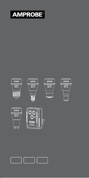
ADPTR-KIT-1
ADPTR-E14
ADPTR-E27
ADPTR-GU10
ADPTR-B15
ADPTR-B22
ADPTR-SCT
Light-check /
Socket-check adapter / incl. kit
Instruction Manual
ENG FRE
SPA
Page 2

Page 3

ADPTR-KIT-1
ADPTR-E14
ADPTR-E27
ADPTR-GU10
ADPTR-B15
ADPTR-B22
ADPTR-SCT
Light-check /
Socket-check adapter / incl. kit
Instruction Manual
9/2018, 6010869 B
©2018 Amprobe
All rights reserved. Printed in China
English
Page 4

Limited Warranty and Limitation of Liability
Your Amprobe product will be free from defects in
material and workmanship for one year from the date
of purchase unless local laws require otherwise. This
warranty does not cover fuses, disposable batteries
or damage from accident, neglect, misuse, alteration,
contamination, or abnormal conditions of operation
or handling. Resellers are not authorized to extend any
other warranty on the behalf of Amprobe. To obtain
service during the warranty period, return the product
with proof of purchase to an authorized Amprobe
Service Center or to an Amprobe dealer or distributor.
See Repair Section for details. THIS WARRANTY IS YOUR
ONLY REMEDY. ALL OTHER WARRANTIES - WHETHER
EXPRESS, IMPLIED OR STATUTORY - INCLUDING IMPLIED
WARRANTIES OF FITNESS FOR A PARTICULAR PURPOSE
OR MERCHANTABILITY, ARE HEREBY DISCLAIMED.
MANUFACTURER SHALL NOT BE LIABLE FOR ANY
SPECIAL, INDIRECT, INCIDENTAL OR CONSEQUENTIAL
DAMAGES OR LOSSES, ARISING FROM ANY CAUSE OR
THEORY. Since some states or countries do not allow
the exclusion or limitation of an implied warranty or of
incidental or consequential damages, this limitation of
liability may not apply to you.
Repair
All Amprobe returned for warranty or non-warranty
repair or for calibration should be accompanied by
the following: your name, company’s name, address,
telephone number, and proof of purchase. Additionally,
please include a brief description of the problem or the
service requested and include the test leads with the
meter. Non-warranty repair or replacement charges
should be remitted in the form of a check, a money
order, credit card with expiration date, or a purchase
order made payable to Amprobe.
In-warranty Repairs and Replacement – All
Countries
Please read the warranty statement and check your
battery before requesting repair. During the warranty
period, any defective test tool can be returned to your
Amprobe distributor for an exchange for the same or
like product. Please check the “Where to Buy” section
on amprobe.com for a list of distributors near you.
Additionally, in the United States and Canada, inwarranty repair and replacement units can also be sent
to an Amprobe Service Center (see address below).
2
Page 5

Non-warranty Repairs and Replacement – United
States and Canada
Non-warranty repairs in the United States and Canada
should be sent to an Amprobe Service Center. Call
Amprobe or inquire at your point of purchase for
current repair and replacement rates.
USA: Canada:
Amprobe Amprobe
Everett, WA 98203 Mississauga, ON L4Z 1X9
Tel: 877-AMPROBE (267-7623) Tel: 905- 890-7 600
Non-warranty Repairs and Replacement – Europe
European non-warranty units can be replaced by your
Beha-Amprobe distributor for a nominal charge. Please
check the “Where to Buy” section on beha-amprobe.com
for a list of distributors near you.
Beha-Amprobe
Division and reg. trademark of Fluke Corp. (USA)
Germany* United Kingdom
In den Engematten 14 52 Hurricane Way
79286 Glottertal Norwich, Norfolk
Germany NR6 6JB United Kingdom
Phone: +49 (0) 7684 8009 - 0 Phone: +44 (0) 1603 25 6662
beha-amprobe.de beha-amprobe.com
The Netherlands - Headquarters**
Science Park Eindhoven 5110
5692 EC Son
The Netherlands
Phone: +31 (0) 40 267 51 00
beha-amprobe.com
*(Correspondence only – no repair or replacement
available from this address. European customers
please contact your distributor.)
**single contact address in EEA Fluke Europe BV
3
Page 6
Amprobe Light-Check Adapters
enable ease-of-use with single-handed
operation and ensure low contact
resistance. Maintenance free, they
feature small robust housings with an
additional finger guard safety barrier.
Light-Check Adapters are ideal for use
with installation testers, insulation
testers and wire tracers, as well as for
voltage measurements and monitoring
in power quality studies.
APPLICATIONS
The Adapters can be used in conjunction
with a wide variety of test equipment
that uses test leads terminating in 4 mm
safety connectors. The Adapters enable
a range of tests to be conducted on light
fitting terminals and ensure a good,
reliable and safe contact, eliminating
the need to hold test probes in place.
ADPTR-KIT1 CONTENTS
The Light-Check Adapter Kit consists of
a complete set of 5 Adapters (E27, B22,
E14, B15, GU10) with carrying case.
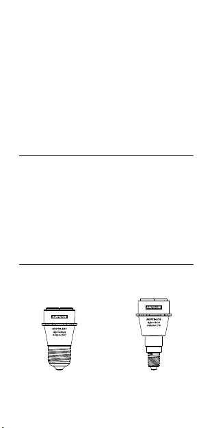
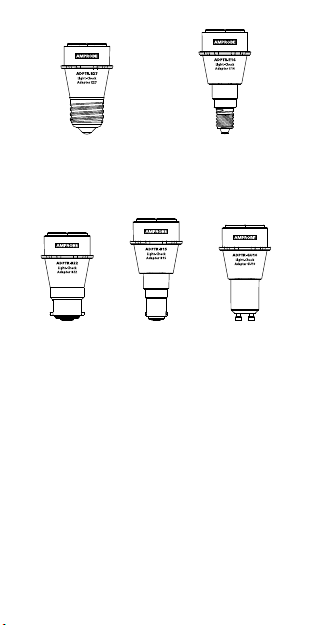
ADPTR-E27
Light-Check
Adapter
4
ADPTR-E14
Light-Check
Adapter
Page 7
Phase (red) and neutral (black) are
marked on Adapters E27 and E14.
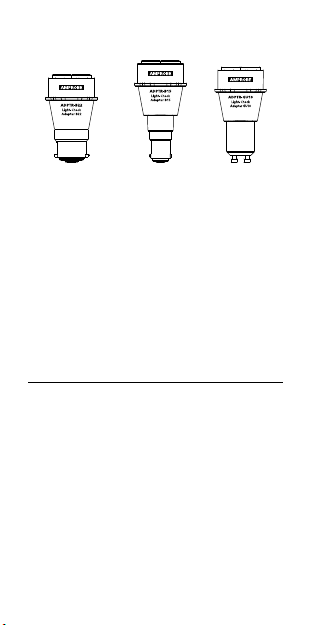
ADPTR-B22
Light-Check
Adapter
Phase and neutral are not marked for
Adapters B22, B15 and GU10 due to
the geometry of these sockets. Detect
phase and neutral by using a suitable
tester if necessary.
First connect test leads on the test
device, then to the Adapter. Ensure
correct connection of phase and
neutral if required.
ADPTR-B15
Light-Check
Adapter
ADPTR-GU10
Light-Check
Adapter
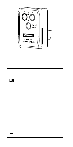
SOCKET-CHECK ADAPTER
1. Plug the adapter into the mains
outlet to be tested.
2. The connections are marked as
follows:
a. Black: Neutral.
b. Red: Phase.
c. Green: Earth.
3. Connect test leads first on the
test device, then to the adapter.
Ensure correct connection of phase,
neutral and earth.
4. Conduct the test.
5
Page 8
SYMBOLS
Caution! Risk of electric
X
shock
Caution! Refer to the
�
explanation in this manual
Consult user documentation
The equipment is protected
by double insulation or
T
reinforced insulation
Earth ground
J
Overvoltage category II is for
CAT II
equipment to be supplied
from the building wiring
Certified by CSA Group
to North American safety
standards
Do not dispose of this product
as unsorted municipal waste –
=
contact a qualified recycler
6
Page 9

SAFETY INFORMATION
The adapters comply with:
IEC/EN 61010-1 3rd Edition, UL61010-
1 3rd Ed. and CAN/CSA C22.2 No.
61010-1-12, pollution degree 2
X�
Warning
To prevent possible electrical shock,
fire, or personal injury:
• Read the operating instructions
before use and follow all safety
instructions.
• Comply with local and national
safety codes. Use personal
protective equipment (approved
rubber gloves, face protection,
and flame resistant clothes) to
prevent shock and arc blast injury
where hazardous live conductors
are exposed.
• Use the adapters only as
specified, or the protection
supplied by the product can be
compromised.
• Do not work alone.
• Do not use the adapters if they
appear damaged. Examine the
adapter for damaged insulation
or exposed metal.
• Test the adapter’s terminal
continuity both before and after
use to ensure the adapter is in
good working condition.
7
Page 10

• Do not apply more than the rated
voltage and rated current.
• Do not touch voltages >30 V AC
RMS, 42 V AC peak, or 60 V DC.
These voltages pose electrical
shock hazards. Keep fingers
behind the finger guards of the
adapter.
• Do not exceed the Measurement
Category (CAT) rating of
the lowest rated individual
component of a product, probe,
or accessory.
• If the adapter is used in a manner
not specified in the user manual,
the protection provided by the
equipment may be impaired.
• Measurements can be adversely
affected by impedances of
additional operating circuits
connected in parallel or by
transient currents.
• Do not use the adapter with any
of the parts removed.
• Do not use the adapter around
explosive gas, vapor, dust or wet
environments.
8
Page 11

SPECIFICATIONS
Light-check adapter:
Voltage
range
Frequency
range
Max.
current
Operating
time
Operating
altitude
Operating
temperature
and
humidity
Storage
conditions
Drop proof 3.28 ft (1 m)
Pollution
degree
Overvoltage
category
Electrical
safety
Agency
approval
0 to 300 V AC
Socket-check adapter:
0 to 120 V AC
50 Hz to 60 Hz
Light-check adapter:
2 A
Socket-check
adapter: 4 A
Continuous
6561 ft (2000 m)
32 °F to 104 °F
(0 °C to 40 °C),
80% RH (without
≤
condensation)
32 °F to 104 °F
(0 °C to 40 °C),
80% RH (without
≤
condensation)
2
Light-check adapters:
CAT II 300 V
Socket-check adapter:
CAT II 120 V
IEC 61010-1, UL61010-1,
CAN/CSA C22.2
No. 61010-1-12
9
Page 12

Size
(H x W x L)
Weight
ADPTR-E27: Approx.
2.8 x 1.6 x 1.2 in
(70.8 x 40.4 x 31.3 mm)
ADPTR-E14: Approx.
3.2 x 1.6 x 1.2 in
(81.3 x 40.4 x 31.3 mm)
ADPTR-B22: Approx.
2.7x 1.6 x 1.2 in
(68 x 40.4 x 31.3 mm)
ADPTR-B15: Approx.
3.1 x 1.6 x 1.2 in
(78.8 x 40.4 x 31.3 mm)
ADPTR-GU10: Approx.
2.9 x 1.6 x 1.2 in
(74.7 x 40.4 x 31.3 mm)
ADPTR-SCT: Approx.
2.95 x 1.97 x 2.56 in
(75 x 50 x 65 mm)
ADPTR-E27: Approx.
0.06 lb (27 g)
ADPTR-E14: Approx.
0.05 lb (23.5 g)
ADPTR-B22: Approx.
0.06 lb (29.5 g)
ADPTR-B15: Approx.
0.06 lb (25 g)
ADPTR-GU10: Approx.
0.06 lb (29.5 g)
ADPTR-SCT:
0.125 lb (0.057 kg)
Approx.
CARE
The Adapters can be cleaned with a
mild solution of soapy water. Apply
sparingly with a soft cloth and allow
to dry completely before using. Do not
use aromatic hydrocarbons, gasoline,
or chlorinated solvents for cleaning.
10
Page 13

ADPTR-KIT-1
ADPTR-E14
ADPTR-E27
ADPTR-GU10
ADPTR-B15
ADPTR-B22
ADPTR-SCT
Adaptateur pour vérification de
lampe / Testeur de prise / dont kit
Mode d’emploi
9/2018, 6010869 B
©2018 Amprobe
Tous droits réservés. Imprimé en Chine
1
Français
Page 14

Garantie limitée et limitation de responsabilité
Votre produit Amprobe sera exempt de défauts de
matériaux et de fabrication pendant un (1) an à
compter de la date d’achat, sauf exigence contraire
en vertu de la juridiction locale. Cette garantie ne
s’applique pas aux fusibles, aux piles jetables ou
endommagées par accident, à la négligence, à la
mauvaise utilisation, à l’altération, à la contamination
ou aux conditions anormales d’utilisation ou de
manipulation. Les revendeurs ne sont pas autorisés à
prolonger toute autre garantie au nom de Amprobe.
Pour une réparation au cours de la période de garantie,
retournez le produit avec la preuve d’achat à un centre
de service autorisé par Amprobe ou à un revendeur ou
un distributeur Amprobe. Voir la section Réparation
pour plus de détails. CETTE GARANTIE EST VOTRE SEUL
RECOURS. TOUTES LES AUTRES GARANTIES – QU’ELLES
SOIENT EXPLICITES, IMPLICITES OU JURIDIQUES – Y
COMPRIS LES GARANTIES IMPLICITES D’ADAPTATION
À UN USAGE PARTICULIER OU MARCHAND, SONT
EXCLUES. LE FABRICANT NE SERA PAS RESPONSABLE
DES DOMMAGES SPECIAUX, INDIRECTS, ACCESSOIRES
OU CONSECUTIFS PROVENANT DE TOUTE CAUSE
OU THEORIE. Etant donné que certains pays ou
états n’autorisent pas l’exclusion ou la limitation
des garanties implicites ou des dommages directs ou
indirects, cette limitation de responsabilité peut ne pas
s’appliquer à vous.
Réparation
Tout produit Amprobe retourné pour réparation sous
garantie ou hors garantie ou pour l’étalonnage doit
être accompagné des documents suivants :votre nom,
le nom de votre société, votre adresse, votre numéro de
téléphone et la preuve d’achat. De plus, veuillez inclure
une brève description du problème ou du service
demandé et incluez les cordons de mesure avec le
compteur. Les frais de réparation ou de remplacement
non garantis doivent être réglés sous forme de chèque,
mandat, carte de crédit avec date d’expiration ou bon
de commande payable à Amprobe/Beha-Amprobe
Réparation et remplacement couverts par la
garantie – Tous les pays
Veuillez lire la déclaration de garantie et vérifier la pile
avant de demander une réparation. Pendant la période
de garantie, tout outil de vérification défectueux
peut être retourné à votre distributeur Amprobe
pour un échange de produit identique ou similaire.
Veuillez consulter la section « Où acheter » sur le site
amprobe.com pour obtenir une liste des distributeurs
près de chez vous. En outre, aux États-Unis et au
Canada, les réparations sous garantie et les unités de
remplacement peuvent également être envoyés à un
centre de service Amprobe (voir adresse ci-dessous).
2
Page 15

Réparation et remplacement non couverts par la
garantie – États-Unis et Canada
Pour les réparations non couvertes par la garantie aux
États-Unis et au Canada, l’appareil doit être envoyé à
un centre de service Amprobe. Appelez Amprobe ou
renseignez-vous auprès de votre point de vente pour
les tarifs de réparation et de remplacement actuels.
États-Unis : Canada :
Amprobe Amprobe
Everett, WA 98203 Mississauga ON L4Z 1X9
Tél. : 877-AMPROBE (267-7623) Tél . : 9 05-8 90-76 00
Réparation et remplacement non couverts par la
garantie – Europe
Les unités hors garantie européenne peuvent
être remplacées par votre distributeur Amprobe/
Beha-Amprobe pour une somme modique. Veuillez
consulter la section « Où acheter » sur le site behaamprobe.com pour obtenir une liste des distributeurs
près de chez vous.
Beha-Amprobe
Division et marque déposée de Fluke Corp. (USA)
Allemagne* Royaume-Uni
In den Engematten 14 52 Hurricane Way
79286 Glottertal Norwich, Norfolk
Allemagne NR6 6JB Royaume-Uni
Tél. : +49 (0) 7684 8009 - 0 Tél. : +44 (0) 1603 25 6662
beha-amprobe.de beha-amprobe.com
Pays-Bas - Siège social**
Science Park Eindhoven 5110
5692 EC Son
Pays-Bas
Tél. : +31 (0) 40 267 51 00
beha-amprobe.com
*(Correspondance uniquement : aucune réparation ou
remplacement à cette adresse.
Clients européens, veuillez contacter votre distributeur.)
**adresse de contact unique dans l’EEE Fluke Europe BV
3
Page 16

Les adaptateurs vérificateurs de lampe
Amprobe permettent une utilisation
facile avec un fonctionnement à
une seule main et assurent une
faible résistance de contact. Sans
maintenance, ils disposent de
petits logements robustes avec une
barrière de sécurité protège-doigts
supplémentaire. Les adaptateurs
vérificateurs de lampe sont une
solution idéale pour une utilisation
avec des testeurs d’installation, des
testeurs d’isolement et des traceurs
de fils, ainsi que pour les mesures de
tension et le contrôle dans les études
de qualité d’alimentation.
APPLICATIONS
Les adaptateurs peuvent être utilisés
avec un large choix d’équipements
de test exploitant des câbles d’essai
se terminant par des connecteurs de
sécurité de 4 mm. Les adaptateurs
permettent de conduire un grand
nombre de tests sur des bornes de
luminaires et garantissent un bon
contact, fiable et sûr, éliminant le
besoin de maintenir les sondes de test
en place.
CONTENU DU ADPTR-KIT1
Le kit adaptateur vérificateur de
lampe est composé d’un ensemble
complet de 5 adaptateurs (E27, B22,
E14, B15, GU10) avec une mallette de
transport.
4
Page 17

Adaptateurs
vérificateurs
de lampe
ADPTR-E14
Adaptateurs
vérificateurs
de lampe
ADPTR-E27
La phase (rouge) et le neutre (noir) sont
marqués sur les adaptateurs E27 et E14.
ADPTR-B22
Adaptateurs
vérificateurs
de lampe
ADPTR-B15
Adaptateurs
vérificateurs
de lampe
ADPTR-GU10
Adaptateurs
vérificateurs
de lampe
La phase et le neutre ne sont pas
marqués sur les adaptateurs B22, B15
et GU10 en raison de la géométrie de
ces douilles. Détectez la phase et le
neutre à l’aide d’un testeur adapté si
nécessaire.
Connectez d’abord les fils de test sur le
dispositif de test, puis à l’adaptateur.
Assurez-vous de la connexion correcte
de la phase et du neutre si nécessaire.
5
Page 18

ADAPTATEUR DE PRISE
1. Branchez l’adaptateur dans la
prise secteur à tester
2. Les connexions sont marquées
comme suit :
a. Noir: Neutre
b. Rouge: Phase
c. Vert: Terre
3. Connectez d’abord les fils de test
sur le dispositif de test, puis à
l’adaptateur. Assurez-vous de la
connexion correcte de la phase,
du neutre et de la terre.
4. Effectuez le test.
6
Page 19

SYMBOLES
Attention! Risque de choc
X
électrique
Attention! Reportez-vous
�
aux explications de ce guide
Consultez la documentation
utilisateur
Cet équipement est protégé
par une isolation double ou
T
renforcée
Prise de terre
J
La catégorie de surtension II
est destinée aux équipements
CAT II
à alimenter depuis le câblage
des bâtiments
Certifié par le Groupe CSA
selon les normes de sécurité
d’Amérique du Nord
Ne jetez pas ce produit avec les
déchets municipaux non triés :
=
contactez un recycleur qualifié
CONSIGNES DE SÉCURITÉ
Les adaptateurs respectent les
normes suivantes :
IEC/EN 61010-1 3e Édition, UL61010-1
3e Éd. et CAN/CSA C22.2 No. 610101-12, degré de pollution 2
7
Page 20

X� Avertissement
Pour éviter tout risque
d’électrocution, de brûlure ou de
blessure :
• Lisez le mode d’emploi avant
utilisation et suivez toutes les
instructions de sécurité.
• Conformez-vous aux normes
locales et nationales de sécurité.
Utilisez de l’équipement de
protection personnelle (gants
en caoutchouc approuvés,
protection faciale, vêtements
ignifuges) pour éviter les chocs
et les blessures lorsque des
conducteurs en fonctionnement
sont exposés.
• Utilisez les adaptateurs
uniquement comme indiqué,
ou la protection fournie
par le produit pourrait être
compromise.
• Ne travaillez pas seul.
• N’utilisez pas les adaptateurs
s’ils semblent endommagés.
Examinez l’adaptateur pour
vérifier la présence d’isolation
endommagée ou de métal
exposé.
• Testez la continuité des bornes
de l’adaptateur avant et après
utilisation pour vous assurer que
l’adaptateur est en bon état de
fonctionnement.
8
Page 21

• N’appliquez pas plus que la
tension nominale et le courant
nominal.
• Ne touchez pas des objets à
tension > 30 V CA RMS, 42 V CA
crête ou 60 V CC. Ces tensions
posent des risques de choc
électrique. Placez les doigts
derrière les protège-doigts de
l’adaptateur.
• Ne dépassez pas le catégorie
de mesure (CAT) du composant
à catégorie la plus faible d’un
produit, d’une sonde ou d’un
accessoire.
• Si l’adaptateur est utilisé
d’une manière non spécifiée
par le manuel de l’utilisateur,
la protection fournie par
l’équipement peut être altérée.
• Les mesures peuvent être
affectées négativement par
des impédances causées par
des circuits supplémentaires
connectés en parallèle ou par des
courants d’équilibrage.
• N’utilisez pas l’adaptateur avec
des pièces retirées.
• N’utilisez pas l’adaptateur à
proximité de gaz, de vapeur,
de poussière explosifs ou
d’environnements humides.
9
Page 22

SPÉCIFICATIONS
Adaptateur de
lampe:
Plage de
tensions
Plage de
fréquences
Courant max.
Durée de
fonctionnement
Altitude
d’utilisation
Température
et humidité de
fonctionnement
Conditions de
stockage
Chute de preuve 99,97 cm (1 m)
Degré de
pollution
Catégorie de
surtension
0 to 300 V AC
Adaptateur de
prise:
0 to 120 V AC
50 Hzà 60 Hz
Adaptateur de
lampe: 2 A
Adaptateur de
prise: 4 A
Continue
199 979,28 cm
(2 000 m)
32 °F à 104 °F
(0 °C à 40 °C),
80 % HR (sans
≤
condensation)
32 °F à 104 °F
(0 °C à 40 °C),
80 % HR (sans
≤
condensation)
2
Adaptateur de
lampe: CAT II 300 V
Adaptateur de
prise: CAT II 120 V
10
Page 23

Sécurité
électrique
Approbations
d'agences
Dimensions
(H x l x L)
IEC 61010-1,
UL61010-1,
CAN/CSA C22.2
No. 61010-1-12
ADPTR-E27:
Environ 2.8 x 1.6 x
1.2 po (70.8 x 40.4
x 31.3 mm)
ADPTR-E14:
Environ 3.2 x 1.6 x
1.2 po (81.3 x 40.4
x 31.3 mm)
ADPTR-B22:
Environ 2.7x 1.6 x
1.2 po (68 x 40.4 x
31.3 mm)
ADPTR-B15:
Environ 3.1 x 1.6 x
1.2 po (78.8 x 40.4
x 31.3 mm)
ADPTR-GU10:
Environ 2.9 x 1.6 x
1.2 po (74.7 x 40.4
x 31.3 mm)
ADPTR-SCT:
Environ
2.95 x
1.97 x 2.56 in (75
x 50 x 65 mm)
11
Page 24

ADPTR-E27:
Environ 0.06 lb
(27 g)
ADPTR-E14:
Environ 0.05 lb
(23.5 g)
ADPTR-B22:
Environ 0.06 lb
Poids
(29.5 g)
ADPTR-B15:
Environ 0.06 lb
(25 g)
ADPTR-GU10:
Environ 0.06 lb
(29.5 g)
ADPTR-SCT:
Environ 0.125 lb
(0.057 kg)
ENTRETIEN
Les adaptateurs peuvent être
nettoyés avec une solution douce
d’eau savonneuse. Appliquer en
petite quantité avec un chiffon
doux et laisser sécher complètement
avant utilisation. Ne pas utiliser
d’hydrocarbures aromatiques,
d’essence ou de solvants chlorés pour
le nettoyage.
12
Page 25

ADPTR-KIT-1
ADPTR-E14
ADPTR-E27
ADPTR-GU10
ADPTR-B15
ADPTR-B22
ADPTR-SCT
Adaptador de comprobación de
luces / comprobación de
tomacorrientes / incluido el kit
Manual de instrucciones
9/2018, 6010869 B
©2018 Amprobe
Todos los derechos reservados. Impreso en China
Español
Page 26

Garantía limitada y limitación de responsabilidad
Su producto Amprobe no presentará defectos
materiales ni de mano de obra durante un año
a partir de la fecha de compra, a menos que las
leyes locales se pronuncien en otro sentido. Esta
garantía no cubre fusibles, pilas desechables o daños
provocados por accidentes, negligencia, mal uso,
alteración, contaminación o condiciones anómalas de
funcionamiento o manipulación. Los revendedores
no tienen autorización para ampliar ninguna otra
garantía en nombre de Amprobe. Para obtener
servicio durante el período de garantía, devuelva
el producto con una prueba de compra a un Centro
de servicio técnico autorizado de Amprobe o a un
proveedor o distribuidor de Amprobe. Consulte la
sección Reparaciones para obtener más detalles.
ESTA GARANTÍA SERÁ SU ÚNICO MEDIO DE
COMPENSACIÓN. POR EL PRESENTE DOCUMENTO,
SE RECHAZAN EL RESTO DE GARANTÍAS (YA SEAN
EXPRESAS, IMPLÍCITAS O LEGALES), INCLUIDAS LAS
GARANTÍAS IMPLÍCITAS, DE ADECUACIÓN PARA UNA
FINALIDAD DETERMINADA O DE COMERCIALIZACIÓN.
EL FABRICANTE NO ASUMIRÁ NINGUNA
RESPONSABILIDAD POR NINGÚN DAÑO O PÉRDIDA
ESPECIAL, INDIRECTA, INCIDENTAL O CONSECUENTE,
QUE SE HAYA PROVOCADO POR CUALQUIER CAUSA
O TEORÍA. Dado que algunos estados o países no
permiten la exclusión o limitación de una garantía
implícita o de daños incidentales o consecuentes, es
posible que esta limitación no se le aplique a usted.
Reparación
Todas las herramientas de Amprobe devueltas para
realizar una reparación cubierta o no por la garantía,
o para realizar tareas de calibración, deben estar
acompañadas de lo siguiente:su nombre, nombre de la
compañía, dirección, número de teléfono y justificante
de compra. Además, incluya una breve descripción
del problema o del servicio solicitado, así como los
conductores de comprobación con el medidor. El
pago de la reparación o sustitución no cubierta por la
garantía se hará a través de un cheque, giro postal,
tarjeta de crédito con fecha de caducidad o una orden
de compra pagadera a Amprobe/Beha-Amprobe
Reparaciones y sustituciones cubiertas por la
garantía: Todos los países
Lea la declaración de garantía y compruebe la
pila antes de solicitar el servicio de reparación.
Durante el período de garantía, puede devolver
cualquier herramienta de comprobación defectuosa
al distribuidor de Amprobe para que se la cambien
por otra nueva o similar. Consulte la sección “Where
to Buy” (Lugares de compra) en amprobe.com para
obtener una lista de los distribuidores cercanos.
2
Page 27

Además, en Estados Unidos y Canadá, las unidades
de reparación y sustitución cubiertas por la garantía
también se pueden enviar al Centro de servicio técnico
de Amprobe (consulte la dirección a continuación).
Reparaciones y sustituciones no cubiertas por la
garantía: Estados Unidos y Canadá
Las reparaciones no cubiertas por la garantía en
Estados Unidos y Canadá se deben enviar a un Centro
servicio técnico de Amprobe. Llame a Amprobe o
pregunte en su punto de compra las tarifas actuales
de reparación y sustitución.
EE.UU.: Canadá:
Amprobe Amprobe
Everett, WA 98203 Mississauga, ON L4Z 1X9
Teléfono: 877-AMPROBE (267-7623) Teléfono: 905-890-7600
Reparaciones y sustituciones no cubiertas por la
garantía – Europa
Su distribuidor de Beha-Amprobe debe reemplazar
las unidades europeas no cubiertas por la garantía
por una cuota nominal. Consulte la sección “Dónde
comprar” en el sitio web beha-amprobe.com para
obtener una lista de distribuidores cercanos.
Beha-Amprobe
División y marca registrada de Fluke Corp. (EE. UU.)
Alemania* Reino Unido
In den Engematten 14 52 Hurricane Way
79286 Glottertal Norwich, Norfolk
Alemania NR6 6JB Reino Unido
Teléfono: +49 (0) 7684 8009 - 0 Phone: +44 (0) 1603 25 6662
beha-amprobe.de beha-amprobe.com
Países Bajos - Sede central**
Science Park Eindhoven 5110
5692 EC Son
Países Bajos
Teléfono: +31 (0) 40 267 51 00
beha-amprobe.com
*(Solo correspondencia: ninguna reparación o
reemplazo disponible en esta dirección. En el caso de
países europeos, se deben poner en contacto con el
distribuidor).
**Única dirección de contacto en EEA Fluke Europe BV
3
Page 28

Los adaptadores de comprobación de
luces Amprobe permiten el uso sencillo
con una sola mano y garantizan una
resistencia de contacto baja. Además,
no requieren mantenimiento y
poseen alojamientos sólidos pequeños
con una barrera de seguridad de
protección para los dedos adicional.
Los adaptadores de comprobación
de luces son ideales para el uso con
testers de instalación, testers de
aislamiento y rastreadores de cables,
así como para las mediciones de
tensión y la supervisión en estudios de
calidad de potencia.
APLICACIONES
Los adaptadores pueden utilizarse
en combinación con una amplia
variedad de equipos de prueba que
utilizan terminales de prueba con
conectores de seguridad de 4 mm.
Los adaptadores permiten realizar
diferentes pruebas en terminales de
luminarias y garantizar un contacto
correcto, confiable y seguro, lo que
elimina la necesidad de sujetar sondas
de prueba en las ubicaciones.
CONTENIDO DEL ADPTR-KIT1
El kit del adaptador de comprobación
de luces está compuesto por un juego
completo de 5 adaptadores (E27,
B22, E14, B15 y GU10) con funda de
transporte.
4
Page 29
ADPTR-E27
Adaptadores de
comprobación
La phase (rouge) et le neutre (noir) sont
marqués sur les adaptateurs E27 et E14.
de luces
ADPTR-E14
Adaptadores de
comprobación
de luces
ADPTR-B22
Adaptadores de
comprobación
de luces
ADPTR-B15
Adaptadores de
comprobación
de luces
ADPTR-GU10
Adaptadores de
comprobación
de luces
Las líneas de fase y neutro no están
indicadas en los adaptadores B22, B15
y GU10 debido a la geometría de estos
conectores. Detecte la línea de fase y
neutro con un tester adecuado, si es
necesario.
En primer lugar, conecte los terminales
de prueba en el dispositivo que
desea probar y, a continuación, en
el adaptador. Verifique la conexión
correcta de la línea de fase y neutro, si
es necesario.
5
Page 30

ADAPTADOR DE
TOMACORRIENTES
1. Coloque el adaptador en el
tomacorriente que desea probar.
2. Las conexiones están indicadas de
la siguiente manera:
a. Negro: neutro
b. Rojo: fase
c. Verde: tierra
3. Conecte los terminales de
prueba en primer lugar en el
dispositivo que desea probar y,
a continuación, en el adaptador.
Verifique la conexión correcta de
la línea de fase, neutro y tierra.
4. Realice la prueba.
6
Page 31

SÍMBOLOS
¡Precaución! Riesgo de
X
descarga eléctrica
¡Precaución! Se refiere a
�
explicaciones de este manual
Consulte la documentación
del usuario
Este dispositivo está
protegido por un doble
T
aislamiento o aislamiento
reforzado
Masa (tierra)
J
La categoría de sobretensión
II corresponde a los equipos
CAT II
a los que se les suministra
alimentación desde el
cableado de la edificación
Certificado por el CSA Group
conforme los estándares de
seguridad de Norteamérica
No deseche este producto
como un residuo municipal
sin clasificación. Comuníquese
=
con un encargado de reciclaje
calificado
INFORMACIÓN DE SEGURIDAD
Les adaptateurs respectent les
normes suivantes : IEC/EN 61010-1
3e Édition, UL61010-1 3e Éd. et CAN/
CSA C22.2 No. 61010-1-12, degré de
pollution 2
7
Page 32

X� Advertencia
Para evitar posibles descargas
eléctricas, incendios o lesiones
personales:
• Lea las instrucciones de
funcionamiento antes de usar y
seguir todas las instrucciones de
seguridad.
• Respete los códigos de seguridad
locales y nacionales. Utilice
equipos de protección individual
(guantes de goma, protección
facial y ropa resistente a la llama
aprobados) para evitar lesiones
por descargas y estallidos por
arco en aquellas situaciones en
las que los conductores vivos
están expuestos.
• Utilice los adaptadores solo como
se especifica, o la protección
suministrada por el producto
podría verse afectada.
• No trabaje solo.
• No utilice los adaptadores si están
dañados. Examine el adaptador
para comprobar si existe un
aislamiento dañado o metales
expuestos.
• Pruebe la continuidad del
terminal del adaptador antes y
después del uso para asegurarse
de que el adaptador funcione
correctamente.
• No aplique más de la tensión
nominal ni la corriente nominal.
8
Page 33

• No toque las tensiones >30 V
de CA RMS, pico de 42 V de CA
o 60 V de CC. Estas tensiones
representan un peligro de
descarga eléctrica. Mantenga los
dedos detrás de las protecciones
para los dedos del adaptador.
• No exceda la clasificación de
categoría de medición (CAT)
del componente individual de
clasificación más baja de un
producto, sonda o accesorio.
• Si el adaptador se usa de una
manera que no esté especificada
por el manual de usuario, la
protección ofrecida por el
producto podría verse afectada.
• Las mediciones pueden verse
afectadas de forma adversa
por impedancias de circuitos
en funcionamiento adicionales
conectados en paralelo o por
corrientes de compensación.
• No utilice el adaptador con
alguna pieza extraída.
• No utilice el adaptador alrededor
de gases explosivos, vapor, polvo
o en ambientes húmedos.
9
Page 34

ESPECIFICACIONES
Adaptador de
Rango de
tensión
Rango de
frecuencias
Corriente máx.
Tiempo de
funcionamiento
Altitud de
funcionamiento
Temperatura y
humedad de
funcionamiento
Condicionales de
almacenamiento
Prueba de caídas 3,28 pies (1 m)
Grado de
polución
lámparas:
0 to 300 V AC
Adaptador de
tomacorrientes:
0 to 120 V AC
50 Hz 60 Hz
Adaptador de
lámparas: 2 A
Adaptador de
tomacorrientes: 4 A
Continuo
6561 pies
(2000 m)
De 32 °F a 104 °F
(de 0 °C a 40 °C),
80% (humedad
≤
relativa) (sin
condensación)
De 32 °F a 104 °F
(de 0 °C a 40 °C),
80% (humedad
≤
relativa) (sin
condensación)
2
10
Page 35

Categoría de
sobretensión
Seguridad
eléctrica
Aprobación de
agencias
Tamaño
(alto x ancho x
largo)
Adaptador de
lámparas:
CAT II 300 V
Adaptador de
tomacorrientes:
CAT II 120 V
IEC 61010-1,
UL61010-1,
CAN/CSA C22.2
núm. 61010-1-12
ADPTR-E27:
Aprox. 2.8 x 1.6 x
1.2” (70.8 x 40.4
x 31.3 mm)
ADPTR-E14:
Aprox. 3.2 x 1.6 x
1.2” (81.3 x 40.4
x 31.3 mm)
ADPTR-B22:
Aprox. 2.7x 1.6 x
1.2” (68 x 40.4 x
31.3 mm)
ADPTR-B15:
Aprox. 3.1 x 1.6 x
1.2” (78.8 x 40.4
x 31.3 mm)
ADPTR-GU10:
Aprox. 2.9 x 1.6 x
1.2” (74.7 x 40.4
x 31.3 mm)
ADPTR-SCT:
Aprox.
2.95 x
1.97 x 2.56
x 50 x 65 mm)
11
”
(75
Page 36

ADPTR-E27:
Aprox. 0.06
libras (27 g)
ADPTR-E14:
Aprox. 0.05
libras (23.5 g)
ADPTR-B22:
Aprox. 0.06
Peso
libras (29.5 g)
ADPTR-B15:
Aprox. 0.06
libras (25 g)
ADPTR-GU10:
Aprox. 0.06
libras (29.5 g)
ADPTR-SCT:
Aprox. 0.125
libras (57 g)
CUIDADO
Los adaptadores pueden limpiarse
con una solución suave de agua con
jabón. Aplique pequeñas cantidades
con un paño suave y espere a que se
seque por completo antes de utilizar.
No utilice hidrocarburos aromáticos,
gasolina o solvente clorinados para
efectuar la limpieza.
12
Page 37

Page 38

Visit amprobe.com for
• Catalog
• Application notes
• Product specifications
• User manuals
Amprobe
amprobe.com
Division of Fluke Corp.
6920 Seaway Blvd.
M/S 143F
Everett, WA 98203 USA
Tel: 877-AMPROBE (267-7623)
Beha-Amprobe
beha-amprobe.com
c/o Fluke Europe BV
Science Park
Eindhoven 5110
NL-5692 EC Son
Tel.: +49 (0) 7684 8009 - 0
®
®
Please
Recycle
 Loading...