

Page 1
OPERATING INSTRUCTIONS
for
AMPROBE ®
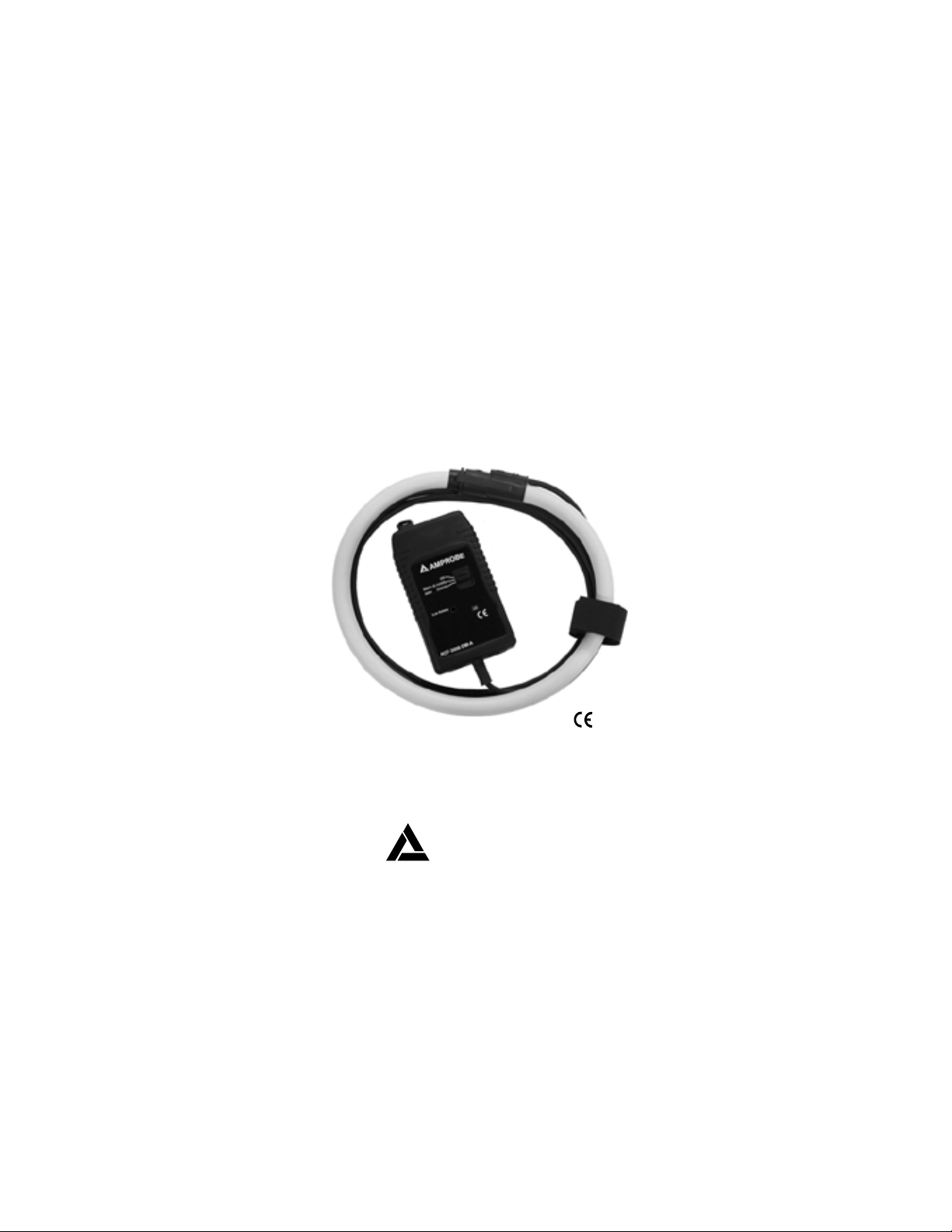
Flexible Current Transducer
Model ACF-3000DM-A
P/N 964774 rev.A
AMPROBE
1
Page 2

TABLE OF CONTENTS
LIMITED WARRANTY ..................................................................................3
INTRODUCTION ..........................................................................................4
ACF-3000DM-A ELECTRONICS PACKAGE................................................4
FLEXIBLE AC CURRENT TRANSDUCER....................................................6
OPERATION..................................................................................................7
MAINTENANCE ............................................................................................8
BATTERY REPLACEMENT ..........................................................................9
SPECIFICATIONS ......................................................................................10
2
Page 3

LIMITED WARRANTY
Congratulations! You are now the owner of an AMPROBE® instrument. It has
been quality crafted according to the highest standards of quality and workmanship. This instrument has been inspected for proper operation of all its
functions and tested by qualified factory technicians according to the long-established standards of AMPROBE®.
Your AMPROBE® instrument has a limited warranty against defective materials and/or workmanship for one year from the date of purchase provided
that the seal is unbroken or, in the opinion of the factory, the instrument has
not been tampered with or taken apart.
Should your instrument fail due to defective materials, and/or work manship during the one year warranty period, return it along with a
copy of your dated bill of sale which must identify instrument by model
number and manufacturing number.
AMPROBE
Tel: 305-423-7500
Fax: 305-423-7554
Tech. Support: 1-800-327-5060
Outside the U.S.A. the local Amprobe representative will assist you. Above
limited warranty covers repair and replacement of instrument only and no
other obligation is stated or implied.
3
Page 4

! ! WARNING ! !
(Do not use until you have read this!)
High-voltage potentials may exist in the vicinity of the desired current
measurements. Use locally approved safety procedures when working near high-voltage potentials. It is recommended not to install the
Flexible Transducer around a live bus that is at a high-voltage potential. If installation is not possible when the bus is disconnected from
main supply, use appropriate gloves and/or equipment that are approved for working around high-voltage potentials when installing the
Flexible Transducer in the vicinity of these hazardous potentials.
I N T R O D U C T I O N
The AMPROBE Flexible AC Current Transducer Model A C F - 3 0 0 0 D M - A is an
assembly similar in purpose to a CTor current transformer. It may be used to
measure AC currents from as low as several amps to a maximum of 3.0kA
rms. The device output is an analog voltage that is proportional to the current
in the conductor. The output signal is isolated from the hazardous conductor
potential and is an exact replica of the AC current waveform in the conductor.
The output signal is available via a 2 pin snap connector.
A C F - 3 0 0 0 D M - A ELECTRONICS PA C K A G E
The A C F - 3 0 0 0 D M - A electronics package is permanently connected to the
transducer and comes standard with two ranges selectable by the switch
mounted on the side of the electronics package. The ranges are 300A a n d
3 . 0 k A yielding respectively 300A and 3.0kA rms AC as the maximum current
that can be measured. When one of the ranges is selected, the unit is automatically turned on.
N o t e : The 3.0kArange should only be selected if the measured current
is over 300A.
4
Page 5

When the A C F - 3 0 0 0 D M - A is turned on, the LED mounted behind the front
label blinks once, then goes out to minimize drain on the battery. When the
batteries are nearing the end of their life the LED flashes approximately twice
per second, the batteries should be replaced and soon. If the LED fails to flash
once when the unit is turned on, the batteries are dead, replace immediately.
The A C F - 3 0 0 0 D M - A comes equipped with an external mini jack located
on the package. This is for those wanting to supply power to the
A C F - 3 0 0 0 D M - A for a longer period than the internal battery life will allow.
An external DC power supply is available for this purpose but is sold as an
option . The power required is +3.0VDC/10mA.
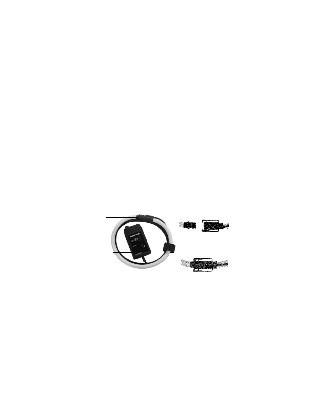
FLEXIBLE AC CURRENT TRANSDUCER
Fig. 1 - ACF-3000DM ELECTRONICS PACKAGE
Fig. 2a - ACF-5A: OUTPUT SIGNAL
SUPPLIED ADAPTER FOR THE DM-II™
Fig. 2b - ACF-5CE: OUTPUT SIGNAL
SUPPLIED ADAPTER FOR DM-II
PRO & DM-II CE
5
Page 6
The A C F - 3 0 0 0 D M - A design utilizes the light weight and flexibility of the Flexible AC Current Tr a n s d u c e r. This transducer is a versatile current probe that
may be wrapped around most conductors. Its application versatility and highvoltage isolation rating clearly distinguish the ACF-3000DM from other current
measuring methods. The measuring transducer is constructed from nonferrous materials, minimizing any circuit loading.
N o t e : The A C F - 3 0 0 0 D M - A will produce twice the output if you wrap the
transducer around the conductor twice.
The frequency response of the A C F - 3 0 0 0 D M - A is wide compared to conventional CTs. This allows the user to monitor a much wider range of line harmonic components than conventional CTs allow. The A C F - 3 0 0 0 D M - A was designed to be very flexible, larger in aperture and smaller in cross section than
many conventional CTs. This allows measurement in tight places as never
before possible.
O P E R AT I O N
LATCH
Fig. 4 - LATCH OPENED
ELECTRONICS
PACKAGE
Fig. 5 - LATCH CLOSEDFig. 3 - ACF-3000 DM-A
6
Page 7

The A C F - 3 0 0 0 D M - A was designed to allow the operator to connect this measurement device around a conductor without disconnecting the conductor as
many CTs presently demand. The Flexible AC Current Transducer is installed
around the conductor with the molded-in arrow on the latch (Fig. 4) pointing in
the direction of conventional current flow. Conventional current flow is defined
as current flowing from the positive to the negative potential, or in case of A C
current the arrow should face the load.
The Flexible AC Current Transducer must be installed with the interconnection
cable on the outside of the loop when the latch is engaged. The polarity
a r r o w, the double insulation, and the warning symbols will all be on the outside of the loop.
There is minimal shock hazard using the ACF-3000DM-A, as the transducer
does not generate high voltages at low frequencies. Each transducer has
been Hi-Pot tested to several thousand volts with no voltage breakdown. T h i s
particular characteristic allows high-current measurement (with a wide
frequency bandwidth) of conductors at less than 600VAC potential to earth.
Do not exceed the minimum bending radius of the Flexible AC Current Tr a n sducer when installing the transducer around the conductor. Exceeding the
bending radius will degrade the measurement accuracy.
Make sure the Flexible AC Current Transducer and its output cable are clean
before installing them around the conductor. If the transducer and cable are
not clean, the contaminants on them may provide a conductive path for a
high-voltage breakdown. Also, check the transducer and output cable for cuts
and abrasions. Do not use the transducer if damaged.
To measure AC current, open the A C F - 3 0 0 0 D M - A by squeezing the latch,
encircle the conductor to be measured, then snap the A C F - 3 0 0 0 D M - A e n d s
together (Fig. 4). Select desired amps range using the switch on the side of
the electronics package (Fig. 2).
7
Page 8

Connect the A C F - 3 0 0 0 D M - A output cable to your measuring instrument using
an adapter.
Set up the A C F - 3 0 0 0 - D M - A range to either 300 or 3000A respective to the
setup on the measuring instrument
E x a m p l e :
Range (Amps) Proper Setup on the DM-II Proper Setup on the
< 3 0 0 A C F 3 0 0 0 3 0 0 3 0 0
< 3 0 0 0 A C F 3 0 0 0 3 0 0 0 3 0 0 0
O u t p u t :
300ARange: 1.0mVAC/Amp
3000A Range: 0.1mVAC/Amp
Return the ACF-3000 range switch to the OFF position when measurement is
completed to preserve battery life.
A C F 3 0 0 0 - D M - A
M A I N T E N A N C E
Preventive maintenance primarily consists of cleaning the transducers and
cables to prevent surface contamination. Use a mild detergent and water to
clean the transducers and cables. Remove the detergent with clear water,
then wipe dry with a clean cloth.
N o t e : The use of solvents as cleaners is not recommended unless
thoroughly tested and found harmless to all surfaces and parts.
Do not submerse current transducer into water or other fluids.
8
Page 9

B AT T E R Y R E P L A C E M E N T
1) Using a coin, turn a lock from close position marked as
to open marked as
2) Open the cover of the battery compartment by lifting it.
3) Replace batteries (note the polarization marked on the bottom of the battery compartment).
4) Replace the cover of the battery compartment.
5 ) Turn a lock from open to close position
! ! SAFETY WARNING ! !
Before removing the battery cover, make sure that the Flexible AC
Current Transducer is removed from around any active conductor.
Fig. 6 - BACK OF ACF-3000DM-AW/ BATTERY COVER REMOVED
9
Page 10

S P E C I F I C AT I O N S
Measuring Ranges: 300A/3000A
Output Sensitivity: 1mV/0.1mV/A (AC coupled)
Accuracy: (at 25°C) ±1% of range
Frequency Range: 10Hz to 5kHz
Phase Error: ±1º (45 to 65 Hz), ±10º (at 5 kHz)
L i n e a r i t y : ±0.2% of reading from 10% to 100% of range
Position Sensitivity: ±2% of range, cable >25mm (1”) from coupling
External Field: ±1% with cable >200mm (8”) from head
Minimum Load: 100kW for specified accuracy
Noise Level: 1.0mV rms (0.3% of range)
Operating Te m p e r a t u r e : -20°C to 85°C (-4°F to 185°F) Electronics
Storage Te m p e r a t u r e : -20°C to 85°C (-4°F to 185°F) Electronics
Gain Va r i a t i o n : ±0.08%/°C
Common Mode Vo l t a g e : Voltage between the Output the Earth must not
Power Supply: 2 x AA/MN1500 LR6 (1.5V) batteries
Battery Life: 4000 hours, 3000 hours typical (4 months cont.)
Low Battery Indication: Red LED flashing
External Power: Battery eliminator, via 2.1mm connector, 3V DC
S a f e t y : BS EN61010-1: 1993, 600V CATIII Pol. Deg 2
E M C : EN61326: 1998
E n c l o s u r e : IP5X, Flame retardant UL94-VO rated
M a t e r i a l : Valox 357 X
Output Connections: Hypotronics connector type DO1EEB306FST
We i g h t : 0.19 kg (0.4 lb)
Measuring Head
Cable length: 610mm (24 inches), double insulated
Cable Diameter: 14.3mm (0.562 inches)
Bend Radius: 38.1mm (1.5 inches) minimum
Connecting Cable: 2m (78.7 inches) long, double insulated
Material: TPE rubber, Polypropylene, UL94-VO rated
Operating Temperature: -20°C to +90°C (-4°F to 194°F) Head
Storage Temperature: -40°C to +105°C (-40°F to 221°F) Head
Safety: BS EN 61010-1: 1993, 600V CAT III Pol. Deg 2
Weight: 0.18kg (0.4 lb)
exceed 30V
Socket type A16M500
10
Page 11

11
Page 12

AMPROBE
Miami, Florida
Phone: 305-423-7500
Fax: 305-423-7554
www.amprobe.com
®
12 Printed in U.K.
 Loading...