

Page 1

SERVICE
If the instrument fails to operate, check battery, test leads, etc and
replace as necessary. If the instrument still malfunctions, please call
the phone number listed below:
Service Division
AMPROBE INSTRUMENT
Miami, Florida 33150
Tel: 800-327-5060
outside the U.S.A. the local Amprobe representative will assist you.
|
®
AMPROBE
DIVISION OF CORE INDUSTRIES INC.
Miami, Florida 33150
Tel: 800-327-5060
Visit our Web-site HTTP://www.AMPROBE.COM
Page 2
USER MANUAL
AUNIQUE AC / DC TRUE RMS
CLAMP-ON MULTIMETER
Manual P/N: 978760
MODEL: ACDC-620T
z
U
®
C
8/97
L
LISTED
|
AMPROBE
Miramar, Florida 33025
Tel: 800-327-5060
®
Page 3

LIMITED WARRANTY
Congratulations! You are now the owner of an AMPROBE®instrument. It has been
quality crafted according to quality standards and contains quality components and
workmanship. This instrument has been inspected for proper operation of all its
functions. It has been tested by qualified factory technicians according to the longestablished standards of AMPROBE®.
Your A M P R O B E
®
instrument has a limited warranty against defective materials
and/or workmanship for two years from the date of purchase provided that, in the
opinion of the factory, the instrument has not been tampered with or taken apart.
Should your instrument fail due to defective materials, and/or workmanship
during the two-year period, please have your dated bill of sale which must
identify the instrument model number and serial number and call the number
listed below:
Service Division
AMPROBE INSTRUMENT
Miami, Florida 33150
Tel: 800-327-5060
1
Page 4

CONTENTS
PÁGINA
LIMITED WARRANTY 1
SAFETYINFORMATION 4
AUNIQUE CLAMP-ON MULTIMETER 6
●
INTRODUCTION 6
USING THE METER SAFELY 8
LCD DISPLAYILLUSTRATION 10
GETTING ACQUAINTED WITH YOUR METER 12
●
ALIGNMENTMARKS 12
●
ROTARYSWITCH 13
●
INPUTTERMINAL 14
●
PUSH BOTTONS 15
PUSH-BOTTONS OPERATIONS 16
POWER ON OPTIONS 18
SPECIALFUNCTIONS INSTRUCTIONS 19
●
Dynamic Recording 19
●
Data Hold 22
●
Zero (Relative)
●
Analog Bargraph 23
●
Auto Power Off and Sleep Mode 24
●
Disable Auto Power Off 25
●
Demostrate Annunciator 25
●
Continuity Function For Ohms Measurement 26
●
1 ms Peak Hold 27
2
Page 5

CONTENTS continued
PAGE
HOW TO OPERATE
●
AC CURRENTMEASUREMENT 29
●
DISTRIBUTION TRANSFORMER MEASUREMENT 29
●
AC MOTOR CURRENTMEASUREMENT 31
●
AC VOLTAGE MEASUREMENT 33
●
RESSISTENCE / CONTINUITYMEASUREMENT 35
●
TEMPERATURE MEASUREMENT 39
●
CAPACITANCE MEASUREMENT 43
ESPECIFICACIONES GENERALES 45
GENERALSPECIFICATIONS 47
ACCESSORIES AND REPLACEMENT PARTS 48
CURENT HARMONICS THEORY 51
●
TRUE RMS MEASUREMENT 53
●
WAVE FORM COMPARISON 54
REFRIGERATION 56
MAINTENANCE 61
●
SERVICE
●
BATERYREPLACEMENT 61
●
CLEANING 64
3
Page 6

SAFETYINFORMATION
c
SAFETYINFORMATION:
●
To ensure that you use meter safely, follow the safety guidelines listed below.
●
This meter is for indoor use, altitude up to 2000m.
●
Avoid working alone. Take precautions when working around moving parts.
●
Use the meter only as specified in this manual. Otherwise, the protection pro
vided by the meter may be impaired.
●
Never measure current while the test leads arer inserted into the input termi
nals.
●
Do not use the metr if it looks dameged.
●
Inspect the leads for damage insulation or exposed metal. Check test lead
continuity. Replace damaged leads
●
Disconnect the power and discharge all high-voltage capacitors before testing.
●
Use caution when working above 60V DC or 30V AC RMS. Such voltages
pose a pose a shock hazard
●
When making measurements, keep your fingers behind the finger guards on
the probe.
4
Page 7

●
Set the proper function and renge before attaching the metr to circuit. To avoid
damaging the meter disconnect the test leads from test points before changing
functions.
●
Read this operation manual completly before using the meter and follow all
safety instructions.
●
The meter is safety-certified in compliance with UL3111-1, C22.2 NO.1010.1-
92 and EN61010(IEC 1010-1, 1010-2031,IEC 1010-2-32) Instalation Category
ll 1000V or instalation Category lll 600V. In order to mantain its insulation
properties, please be sure to use ULListed Category ll 1000V or Category lll
600V probes.
●
insrtallation category (CAT) ll is an environment with smaller trasient overvolt-
age than Installation Category lll.
●
CE requirement: Under the influence of R.F field according to standard, the
supplied test leads will pick up induced noice. To have better shielding tests
are required in order to conform to CE:
1. IEC 801-2: ESD (electro-static discharge) test.
2. IEC-801-3: RFI (Radio frequency Interference) test.
Condition : 27 ~ 500MHz, signal intensity is 3 volts per meter.
3. IEC 801-4: EFT(electro-fast transient) test.
4. EN 55011: EMI (electromagnetic interference) test.
●
Do not allow the temperature sensor to contact a surface which is energized
above 30 V RMS or 60V DC, such voltages pose a shock hazard.
5
Page 8

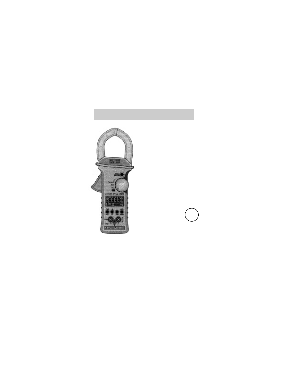
AUNIQUE CLAMP-ON MULTIMETER
c
INTRODUCTION
Measuring current accurately is difficult job in today's industrial plants and commercial buildings.An increasing number of personal computers, adjustable
speed motor drivers, and other types of electronic equipment in short pulses and
are reffered to as non-linear loads.
non-linear loads draw high peak current, causing harmonics in the load current.
this may result in unexplained circuit breaker tripping, or dangerous overheating
of neutral conductors and transformers. Currents containing harmonics can only
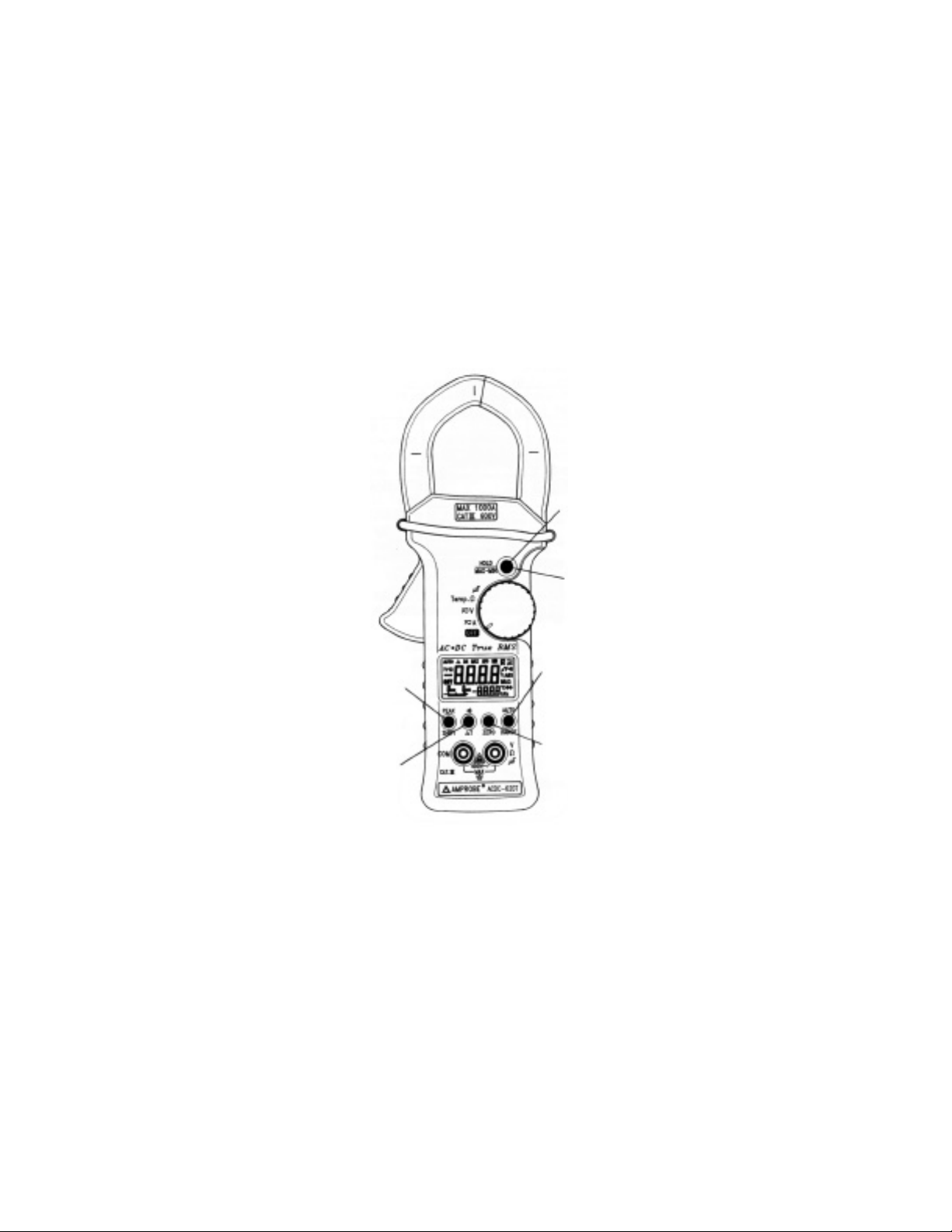
be accurately measured with a true rms or clamp meter. this CLAMP-ON MULTIMETERis shown in Figure1.
This meter has many functions which are shown below:
●
TRUE RMSmeasurement for non-linear and traditional loads.
●
1ms Peak. Hold feature to capture glitch or in-rush current.
●
Differentiation reading for Dual temperature measurement.
●
Start capacitor measurement.
●
Dynamic Recording helps to record the variation of test.
●
Hand Guard for prevention of accidental contact with conductors.
●
Carryng case with shoulder strap
●
Data Hold to freeze displayed digital value.
●
Relative(zero) function
●
Auto and Manual Ranging
6
Page 9
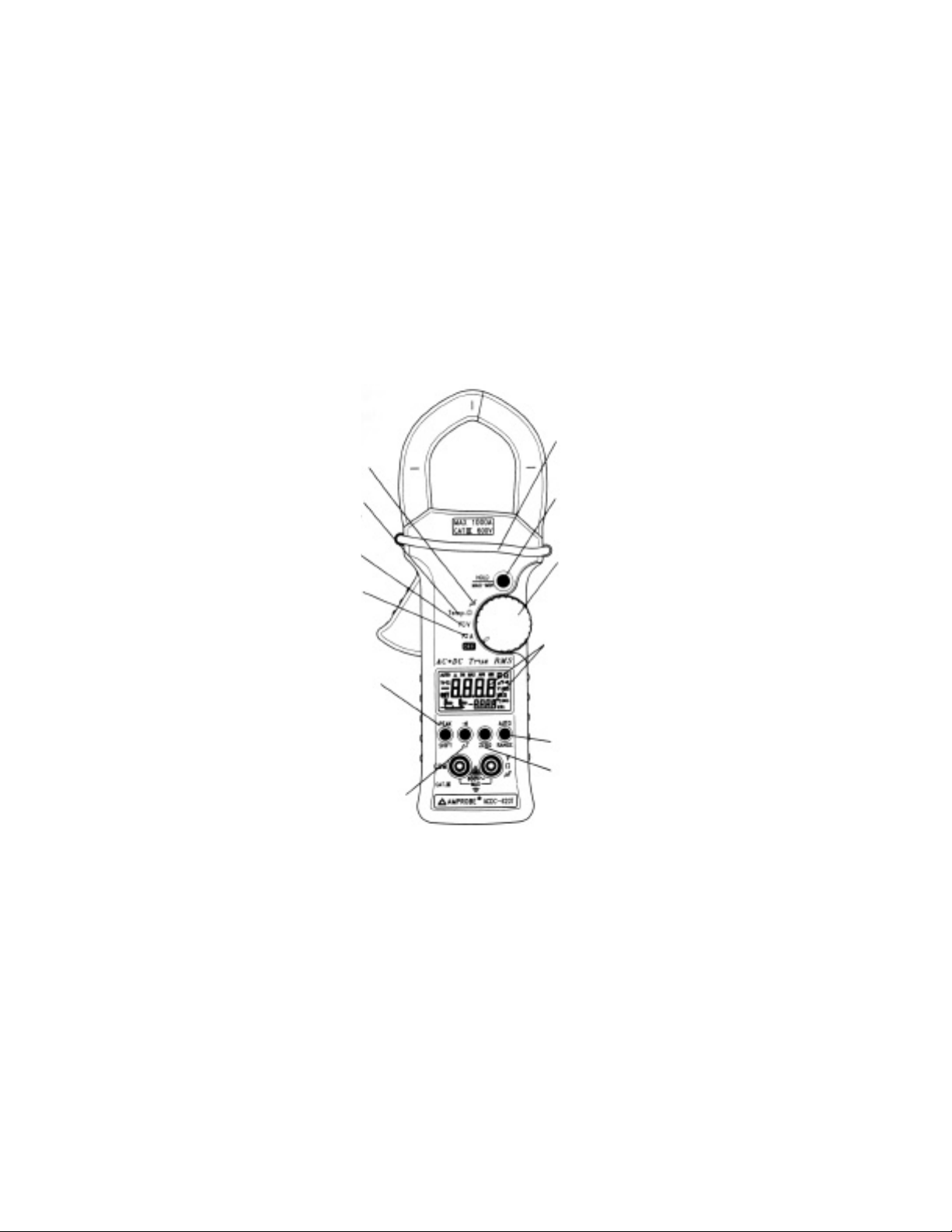
Start capacitor
measurement
Ohm measurement and
k-type temperature
Voltage measurement
Current measurement
1ms Peak Hold for
glitch capture
Hand guard design for
more safety.
Dynamic Recording
helps to record the
variation of tests. And
one touch DATA
HOLD.
Rotary switch for easy
operation.
Dual display to indicate the
of and °C of temperature
simultaneously.
AUTO/MANUAL
SELECT
Different Temperatures
measurement
Figure 1. AUnique Clamp-On Multimeter
Relative (ZERO) mode for
deviation measurements.
7
Page 10

USING THE METER SAFELY
c
WARNING
Read " SAFETYINFORMATION" before using the meter..
c
NOTE
Some typical tests are provided in this manual. These tests are designed to help
you understand how to use the Meter. Consult original manufacturer service
manualfor the test procedures that apply to your particular piece of equipment.
Your Clamp-on multimeter is a hand-held, bateryy operated instrument for testing and troubleshooting electrical and electronic systems. If the meter is damaged or something is missing, contact the place of purchase immediately.
A WARNING identifies conditions and actions that pose hazard(s) to the user; a
CAUTION identifies and actions that may damage the Meter.InternTIONl electrical symbols used are explained inTable 1.
y
x
y
w
G
G
v
AC- Alternating Current
DC- Direct Current
AC and DC-Alternating and Direct Current
Ground
Double Insulation
See Explanation In The Manual
Tabla 1. Símbolos Eléctricos Internacionales
8
Page 11

LCD DISPLAYILLUSTRATION
1) - Negative polarity Annunciator
2) @OFF Auto Power Off Enabled Annunciator
3)
q
Low Battery Annunciator
4) DC Direct Current or Volytage Annunciator
5) AC Alterning Current or Volytage Annunciator
6) AUTO AUTOrange Mode Annunciator
7) DH Data hold Annunciator
8) DH MAX Peak hold Annunciator
9) MAX AVG MIN Dynamic recording mode, presasent reading
10) MAX Maximum reading
11) MIN Minimum reading
12) AVG Average reading
13)
n
))) Continuity function annunciator
14) T1-T2 Delta Temperature (withDKTA-620 adapter)
15) T1 T2 T1 or T2 temperature measurement
16) °C, °F Unit of temperature
17) V Unit of Voltage measurement
18) A Unit of Curent measurement
19) kW Unit of Resistance (ohm) measurement
20) _ Zero (Delta) mode annunciator
21) 8.8.8.8 Digital display for degree °F, A, V and Ω
22) 8000 8000 Analog bar-graph annunciator with sacle indicator.
-IIIIIIIIIl4
23) µF Unit of Capacitor measurement
24) - 8.8.8.8 Digital display for degree C
10
Page 12
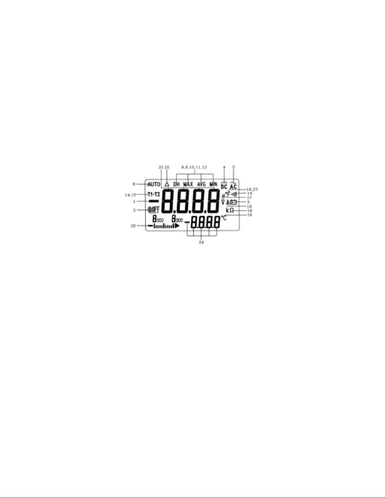
Figure 2. LCD Display
11
Page 13

Getting Acquainted WIth Your Meter
c
ALIGNMENT MARKS
Conductor
MARK
Mark
Figur3 3. Alignment Marks
In order to meet the meeter accuracy spacifications when making a current measurement, the conductor must be inside the jaws and centered within the indicated
marks as much as possible (see Figure 3).
MARK
12
Page 14

Rotary Switch
To turn the meter on and select a function, turn the rotary switch
(Figure 4) to a switch setting. The whole display lights for one second.
Then the meter is ready for use. (if you press and hold down any push
button while turning the meter from OFF to ON, the display remains [it
until the push button is released.)
1. OFF: Power off position.
2. ≅A: AC or DC Current. Default is AC current.
El valor predetermina.
do es corriente alterna (CA).
3. ≅V: AC or DC voltage. Default is AC voltage.
4. Temp Ω: Temperature/Differential Temperature, Ohms,
and Continuity. The continuity buzzer sounds when
test value that is displayed is below 100 counts.
5. µF: Capacitance measurement.
5 µF
4 Temp.Ω
3 V
2 A
y
y
1
OFF
Figure 4. Rotary Switch
13
Page 15
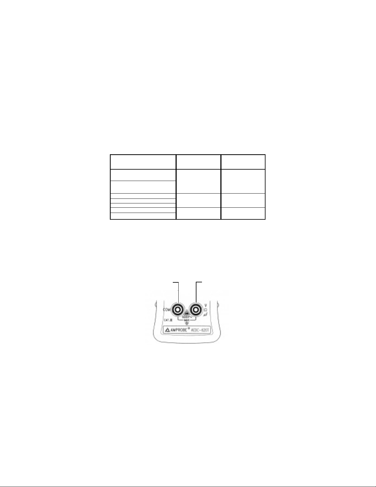
INPUT TERMINAL
To avoid damaging the meter, do not exceed input limit shown below
WARNING
Table 1:
ROTATORYSWITVH FUNCTION
AC 400 ~ 1000V(CATII)
AC 400 ~ 600V(CATIII)
DC 400 ~ 1000V(CATII)
DC 400 ~ 600V(CATIII)
DC 400 ~ 1000 A
AC 400 ~ 1000 A
OHM (Ω)
Capacitance (µF)
Temperature
INPUTTRMINAL
V - Ω - µF & COM
Clamp jaw
V - Ω - µF & COM
INPUTLIMIT
CATII
1000V de CA/1000V DC
CATIIl
600V
1000ARMS
600V RMS
Table 1. Input limit specificationTable 1.
The meter has two input terminals (Figure 5) that are protected
against overloads to the limits shown in the specifications.
1. Terminal común para todas las mediciones excepto la de corriente.
2. Voltios, Ohmios, Prueba de Capacidad y mediciones de
Temperatura.
21
Figure 5. Input Terminal
14
Page 16
2. Press to toggle
"DH" ON/OFF.
3. Press and hold for more
than 1 second to set
Dynamic Recording then
press to step through
MAX,MIN, AVG and present
readings..
1. Press to lselect
DC.AC,DC+AC
Press and hold for
more than 1 second
to toggle, between
PEAK" and DC.
Press to toggle 0
and Temperature
measurements.
5. Press to toggle Continuity
ON/OFF for Ohm measurement.
Press to select T1-T2-T2 for tem
perature measurement.
Figure 6. Push bottons
15
6. In manual range press to step
up 1 range at a time. Press
and hold for 1 sec to select
Auto range.
4. Press to toggle the relative
(ZERO) mode ON/OFF.
Page 17

Push-button Operations
The operation of the push-buttons are outlined below. When a buton is pushed,
an annunciator lights, and the unit beeps. turning the rotary switch to another
switch setting resets all push buttons to thei default states. The pushbuttons are
shown in (page15).
1. Shift / Peak ❍ :
●
This push-button is used for selecting the measurement of either
an Alternating or Direct source, Ohms or Temperature, or for selecting the
PEAK hold function.
●
Press this button momentarily to toggle DC and AC test.
or between Ω and Temperature.
●
To select PEAK hold, press and hold this button until the display shows " DH
MAX" and indicates the PEAK hold mode.
2. Hold ❍: Hold Q: DATAHOLD or Refresh Data Hold
0The data HOLD function allows operator to freeze the
displayed digital value while the analog bargraph
continues to display the present reading.
Press this button momentarily to toggle DH on or off.
The display shows "DH" to indicate the hold function.
If you select " Refresh Data Hold " by Power-ON
Options, the reading is updated to the display
automatically when the reading changes. The beeper
sounds a tone to remind user, that an update has
occurred. Press this button momentarily to toggle DH on or off.
. MAX * MIN 0: Dynamic Recording
3. MAX ●MIN ❍: Dynamic recording
●
To enter or exit dynamic recording mode, press and hold this button to toggle
recording mmode,press and ghold this buton to toggle recording mode on or off.
●
Records maximum, minimum, and calculates tru avarage.
●
Press this button momentarily to cycle through maximum, minimum, average
and present (MAX AVGMIN) readings.
16
Page 18

4. Zero ❍:
●
Push this button momentarily to zero the residual current. Note: Allow the
meter to stabilize before zeroing the display.
The " ∆ " swill also be displayed.
5. ●))) / ∆T m: continuity, Delta Temperature
●
In the Ω position, press this button momenterily to toggle "
●
)))"
continuity ON/OFF. The continuity buzzer sound when test value is below 100
counts (10,0 Ω on auto range). pushing this button for more than 1 secondwill
exit the continuity function and return to the auto-ranging ohm measurement.
●
Press to restart 1ms PEAKhold test afte entering PEAK mode.
●
in the temperature test, push this button momentarily to toggle between T1 T2
temperature and T1 - T2 diferential temperatures test. Note: T1, T2 or T1 - T2
selected on the DKTA-620acessory adapter (optional)..
6. AUTO / RANGE ❍:
●
In auto-range press this button momentarily to select manual range and turn
off the "AUTO" annunciator.
●
In manual range, press this button momentarily to step up 1 range at one time,
press. this buttonfor more than 1 second to enter auto-range.
●
in auto-range, the "AUTO" annunciator is lit an the meter will select an
appropiate renge for measurement being made. If a reading is greater than maximum available renge, "OL" (overload) is displayed on the screen. The meter
selects a lower range when reading is less thn about 9% of fill scale.
17
Page 19

POWER-ON OPTIONS
c
SELECTING POWER-ON OPTIONS
Some options can only be selected when you turn the meter on. These power-on
options are listed in Table 2.
To select power-on press and hold the appriopriate pushbutton while turning the
rotary switch to any ON position. Power-on optons remain selected until the
meter is turned off.
PUSH
BUTTON
DH
❍
MAX●MIN
●)))
❍
∆T
OPTIONDESCRIPTION
Demonstrate Annunciators
To demonstrate the annunciators. to demonstrate all annunciators.
momentarily press any button to exit the demonstration mod.
Disable auto-power off
In general, the auto-power off function turns the meter off if neither
rotary switch nor push button is activated for 15 minutes. You can disable auto-power off function by this option. When auto-power off is disabled the meter will stay in on continuously. Auto-power off is auto disable in Dynamic Recording.
Enable "Refresh data Hold".
Turns off all beeper functions.
Table 2. Power-ON Options
18
Page 20

SPECIALFUNCTIONS INSTRUCTIONS
This clamp-on multimeter provides the operator with various functions including:
c
Dynamic Recording
c
Data Hold
c
Zero (Relative)
c
Analog bargraph
c
Auto Power Off and Sleep Mode
c
Disable Auto Power Off
c
Demonstrate Annunciator of Display
c
Continuity Function For Ohms Measurement
c
1ms Peak hold
c
DYNAMIC RECORDING
The dynamic recording mode can be used to catch intermittent and turn on or off
surges, verify performance while you are away, or take readings while you are
operating the equipment under test and can not watch the meter.
the average reading is useful for smoothing out unstable or changing inputs, estimating the the percent of time a circuit is operational, or verifying circuit performance
The operational procedures are described below::
1. Press and hold the "MAX●MIN" push button to toggle recording mode on or
off. the dynamic recording ode is indicated when the MAX AVG MINannunci
ator turns on. The present valve is stored to memories of maximum, minimum
and average.
2. Press this button momentarily to cycle through maximum, average and present
readings. The MAX, MIN, AVGannunciator turns on respectively to indicate
what value is being displayed. See Figure 7.
19
Page 21

3. The beeper sounds when a new maximun or minimum value is recorded.
4. If an overload is recorded the averaging function is stopped. An average value
becomes "OL" (overloaded.
5. In dynamic recording the auto powe off feature is disabled and the"@OFF"
turns off.
6. By selecting dynamic recording in the auto range, the meter will record the value
of MAX, MIN or AVG for different ranges.
7. The record speed of dynamic reording is about 100 milli-seconds (0.1 second).
8. The average value is the true average of all measured values taken since the
recording mode was entered.
20
Page 22

1. Press for more than 1 second to
enter Dynamic Recording
Figure 7. Display of Dynamic Recording
21
Page 23

c
DATAHOLD
The data HOLD function allos operator to freeze the displayed digital value while
the aanlog bargraph displays present readings. Press "DH" Hold button to enter the
data Hold mode, and the "DH" annunciator is displayed. Press the button again to
exit. The present reading is now shown.
Figura 8. Operación de Retención de Datos (Data Hold)
c
ZERO (RELATIVE)
The ZERO (relative) function subtracts a stored value from the present measurement and displays the result..
1) Press the ZERO button momentarily to set the relative mode. This sets the dis
play to zero and stores the present reading as a reference value. The " ∆ "
annunciator will also be displayed. Press this button again to exit the relative
mode.
2) The ZERO (relative) mode can be set in both the autorange or manual range
mode. The relative mode can't be set when an overload has occurred.
3. When the Dc Current measurement mode is entered, the display will indicate a
non-zero DC Curent (positive or neative) value due to residual magnetism of the
jaw and of the internal sensor. You can use the Zero (relative) function to ZeroAdjust the display.
22
Page 24

Figure 9. relative(Zero) Operation.
c
ANALOGBATRGRAPH
The analog bargraph display provides a 12-segment analog reading representa
tion. The unit of the bargraph is 100 counts/bar.
23
Page 25

Figura 10. Analog Bar graph
c
AUTO POWER OFFAND SLEEPMODE
There are two modes for power saving.
1 ) The instrument will enter the "sleep" mode within 15 minutes, unless:
1-1. Any push buttons have been pressed
1-2. The rotary switch has been changed to another function
1-3. The unit has been set to Dynamic recording mode
1-4. The unit has been set to I ms PEAK hold mode.
1-5. The auto power off has been disabled with powerup option
2) In the sleep mode, the LCD will display a blinking
"@OFF . . . "annunciator.
2-1. To wake-up sleep mode, press any push button for 0.5 sec or rotate rotary
switch.
2-2. Without wake-up, after 15 minutes, the meter will automatically shut off com
pletely.
3) You must turn the rotary switch to the OFF position, then turn it back to a func
tion to activate the meter after an auto power off.
24
Page 26

@OFF ❚ ❚ ❚
Figure 11. Sleep Mode
c
DISABLE AUTO POWEROFF
When the meter is to be used for long periods of time you may want to disable the
auto power off. Once the auto power off function is disabled, the meter will stay on
continuously. The meter is shut off by turning the rotary switch to the OFF position.
To activate this function, press and hold the "HOLD/MAX ●MIN" button and turn the
rotary switch from the OFF position to the desired function. When all annunciators
are displayed, press any button momentarily to exit demonstrate mode, and the
"@OFF" annunciator will be off.
c
DEMONSTRATE ANNUNCIATOR
To demonstrate the annunciators, press "HOLD/MAX ●MIN" button and turn on the
meter simultaneously. All annunciators will be displayed. Press any button to exit
demonstrate mode. Auto power off will be disabled.
25
Page 27

Figure 12. Demostrate Annunciator.
c
CONTINUITY FUNCTION FOR OHMS MEASUREMENT
To enable the continuity function, set the meter to the Ω range.
Press ●))) button momentarily to toggle the CONTINUITYfunction ON/OFF.
The continuity range is 0-400.0 Ω and the beeper will sound if the resistance is less
than 10.0 Ω. If another range is selected, the unit will beep if the value displayed is
less than 100 counts. Momentarily pushing this button again will toggle the beeper
and annunciator on or off.
26
Page 28

Ω
Ω
IIIIIIIIIl4
IIIIIIIIIl4
Figure 14. Continuity Operation
c
1ms Peak Hold
You can use this Meter to analyze components such as power distribution transformers and power factor correction capacitors. The additional features allow the
measurement of the half-cycle peak current by using the I ms peak hold feature.
This allows the determination of the crest factor:
Crest factor = Peak value/True rms value
1 ) Press PEAK button for more than 1 second to toggle 1 ms peak hold mode
ON/OFF.
2) Press PEAK button momentarily to select PEAK+ measurement after entering
the peak mode. The display shows "DH MAX" to indicate the PEAK +. See
Figure 16.
27
Page 29

3) If the reading is " OL", then you can push RANGE button momentarily to change
measuring range and restart the PEAK+ measurement after setting the peak
mode.
4) Press ●)))button to re-set the I ms peak hold again after setting peak mode.
Note: Acrest factor of 1.4 indicates a sinusoidal waveform.
V
Press and Hold
1 second
Press Peak
and 1 second
Hold
V
DH MAX
V
I
IIIl
I
Figure 16. 1ms Peak Hold Display.
28
Page 30

HOW TO OPERATE
c
AC CURRENT MEASUREMENT
WARNING: MAKE CERTAIN THATALLTESTLEADS ARE DISCONNECTED
1 ) Set the rotary switch to " A ".
2) Open the meter jaws and clamp around a single conductor. The most accurate
reading will be obtained by keeping the conductor aligned with the centering
marks on the jaws. Make sure that the jaws are fully closed.
3) Read the display.
FROM THE METER TERMINALS.
29
Page 31

CORRECT
INCORRECT
Figure 17. Measuring AC Current.
30
Page 32

c
DISTRIBUTION TRANSFORMER MEASUREMENT
You can measure current, phase imbalance between phases, and true RMS neutral
current. True RMS measurement yields the effective value.
1) Set the rotary switch to " A ".
2) Clamp around a phase wire of the transformer. Be sure the jaws are completely
closed or measurement will not be accurate.
3) Observe the display for true RMS current.
4) Repeat your measurement for each phase to determine balance. Imbalanced
phases and/or harmonics can cause neutral currents.
5) Observe the display for true RMS current reading. If the phases are balance, any
significant current flow on the neutral may indicate the presence of harmonic cur
rents.
6) Press the HOLD/MAX●MINbutton to freeze the digital display.
7) Press and hold the SHIFTbutton (>I sec) to enter the PEAK mode (DH MAX dis
played). Measure the half cycle PEAK current. Divide first reading into the sec
ond reading to determine crest factor. Acrest factor other than 1.4 is an indication
of harmonic current.
8) Press and hold the SHIFT button (>11 sec) to exit the PEAK mode.
9) Press and hold the HOLD/MAX●MIN (> 1 sec) to enter dynamic recording
mode. Momentarily press HOLD/MAX●MINbutton to review recorded maxi
mum, minimum, and average values.
10) Press and hold the HOLD/MAX●MIN button (> 1 sec) to exit recording.
31
Page 33

Figure 18. Measuring AC Curreft
32
Page 34

c
AC MOTOR CURRENT MEASUREMENT
You can measure starting (inrush) current , running current, and current imbalance in AC Motor circuits. Inrush current is typically 6-8 times the value of running current, depending on the motor type..
1. St the rotary switch to "A".
2. Press and hold the PEAK button(>1sec) to enter 1ms PEAK hold mode.
3. Clamp around a motor phase conductor. Be Sure the clamp jaws are com
pletely closed, or measurement will nor be accurate..
4. press ZERO to set the display to zero.
5. Turn the mmotor on.When the motor gets to the desired speed, obbserve
the display for inrush current reading.
6. If the reading is "OL" , you can push the RANGE button momentarily to
change measuring range. Turn off the motor.
7. repeat your measurament from step 2 through 6 for each phase. Avoltage
imbalance or a shorted motor winding may cause imbalance current..
33
Page 35

Figure 19. Measuring AC Motor Curent
34
Page 36

c
AC VOLTAGE MEASUREMENT
1. Set the rotary switch to "V".
2. Insert the black test lead to "COM" terminal and red test lead to
"V - Ω - µF" terminal.
3. touch the probes to the test points and read the displayed AC Voltage.
35
Page 37

Figure 20. Measuring Voltage.
36
Page 38

c
RESISTANCE / CONTINUITYMEASUREMENT
CAUTION: Make sure that power is removed and all
capacitors have been discharged before measuring.
1) Set the rotary switch to "TEMP. Ω ". OLis displayed.
2) Insert the black test lead to "COM" terminal and red test lead to
" V - Ω - µF " terminal.
3) Short the test leads together and momentarily press the ZERO button to subtract
test lead resistance from measurement.
4) Touch the test leads to the circuit (Fuse Cartridge or other) and read resistance
value in the display.
5) Press ●))) button momentarily to enter continuity function if desired.
6) Repeat steps 3 and 4. The beeper sounds if continuity reading is less
than 10.0 Ω..
7) OL (overload) is displayed if the resistance across the input terminals is greater
than the full-scale rating on the range setting of the instrument. Be sure that the
contact between the probes and the circuit is clean. Dirt, oil, paint, rust or other foreign matter can seriously effect resistance measurements.
37
Page 39

FUSE
CARTRIDGE
Figura 21. Measuring Resistance and Continuity.
38
Page 40

c
TEMPERATURE (K-TYPE) MEASUREMENTS
The ACDC-620TLCD contains a dual display for
Temperature Measurement. The larger digits display oF (Fahrenheit), and the small
digits display oC (Celsius).
Both readings are displayed simultaneously.
CAUTION: Do not allow the temperature sensor to contact a surface which is energized above 30 V RMS or 60 V DC, such voltages pose a shock hazard.
●
To perform single input temperature measurement:
1) Set the rotary switch to "TEMP. Ω ",
2) Insert the model TAC-DMM banana to K-type thermocouple adapter into the
meter. The "+" end of adapter must be inserted into"V - Ω - µF" terminal.
3) Insert the model TPK-56 Type K thermocouple into the TAC-DMM.
4) Secure the beaded end of the K thermocouple to the surface you wish to
measure.
5) Press SHIFT button momentarily to enter temperature measurement mode.
6) Read the displayed temperature.
39
Page 41

Press
Shift
Figure 22. Surface Temperature Measurement.
40
Page 42

●
To perform dual input and/or differential temperature measurement:
1) Set the rotary switch to "TEMP. Ω ".
2) Insert the model DKTA-620 Dual Type K thermocouple adapter into the meter.
The "+" end of the adapter must be inserted into "V - Ω - µF" terminal.
3) 1 nsert two of the model TPK-56 Type K thermocouples into the DIKTA-620.
4) Secure the beaded end of the K thermocouples to the surfaces you wish to
measure.
5) Press SHIFTbutton momentarily to enter temperature measurement mode.
The "T1 T2' annunciator will be displayed.
6) Since the displayed temperature will be based on the position of the selector
switch located on the DKTA-620 adapter, select either T1 or T2 for the desired
measurement.
7) Read the display.
●
To measure differential temperature:
Note: T1 temperature must be greater than T2 for
differential measurement to be correct.
1 ) Set the DKTA-620 selector switch to the "T1-T2" position.
2) Push the ∆T button on the ACDC-620Tmomentarily to enter the Differential
Temperature Mode. The "TI-T2" and "A" annunciators will be displayed.
3) Read the displayed differential temperature.
4) For information on basic refrigeration theory refer to page 56.
41
Page 43

Contact where
you want to measuring
PRESS
∆T
Figure 23. Measuring Temperature on Refrigeration System.
42
Page 44

c
CAPACITANCE MEASUREMENTS
In many instances a motor can not be started due to a failed start/run capacitor. To
test the capacitor:
: Discharge the capacitor before testing.
1 ) Set the rotary switch to "µF" position.
2) Insert the black test lead to "COM" terminal and red test lead to "V - Ω - µF"
terminal.
3) Remove at least one leg of the capacitor from circuit board or device.
4) Touch the test leads across the capacitor and read the display.
Note: If you are measuring a polarity sensitive electrolytic capacitor, touch the red
test lead to the positive end of the capacitor, and the black test lead to the negative
end of the capacitor.
43
Page 45

Rojo
Negro
(-)
(+)
Figure 24. CAPACITANCEMEASUREMENTS.
44
Page 46

GENERALSPECIFICATIONS
Display:
Display: Fully annunciated 4-digit liquid crystal display (LCD) with maximum reading
of 4,000 count. Dual display in Temperature mode. 12 segments analog bar graph.
Automatic polarity indication.
Functions: DCV, ACV, DCA, ACA, OHM, Capacitance and Temperature.
Measuring rate:
3.3 times per second for V, A, Ohm and Temperature tests.
0.5 - 7.6 seconds per time for Capacitance test.
Low battery indicator:
The "'q " appears when the battery voltage drops below 7V
(approx.).
Operating temperature:
0 * C to 50 * C (32 * F to 122 * F), 0 - 80% R.H.
Storage temperature:
-20'C to 60 * C (-4'F to 140 - F), 0 - 80% R. H. with
BATTERYREMOVED.
Temperature coefficient:
0.12 % / *C(fr0m O'C to 18 *C or 28 *C to 50 'C),
0.067 % / 'F(from 32 * F to 64.4 * F or 82.4 * F to 122 * F), or
otherwise specified.
Power supply: Single standard NEDA1604, JIS006P,IEC6F22 carbonzinc or alkaline type 9V battery.
45
Page 47

MAX. Jaw Opening:
To Accommodate Circuit Cables 2" ( 50.8 mm ) diameter.
Dimension:
32 (H) x 64 (W) x 260 (L) mm
1.26"(H) x 2.52"(W) x 10.24"(L)
Weight: 840 grams with battery included. (1.85 lbs with battery included.)
Standard Accessories: Test leads (pair), Manual, Battery and Carrying case.
Optional Accessories: K-type bead probe and Dual input adopter.
Safety: Designed and manufactured to conform to UL3111-1, C22.2 NO. 1010. 1 -
92 and EN61 010 (IEC1 010-1, IEC1010-2-031, fEC-1010-2-032) Installation
Category (Overvoltage Category) 111 OOOV or Installation Category III 60OV,
Pollution Degree 2 environment.
Note: Meter has been submitted for approval to above standard at the time of printing of this manual. Product will be marked accordingly upon approval.
46
Page 48

Accessories and ReplacementsParts
Amprobe P/N Description
DTL-3000
CC-ACDC
978760
MN-1604
DKTA-620
TAC-DMM
TPK-56
Safety Test Leads(included)
Carryimg Case(included)
Instruction Manual(included)
9 Volt Alkaline Battery(included)
Dual input thermocouple adapter(opcional)
Single input thermocouple(opcional)
Type K bead probe(opcional)
47
Page 49

ELECTRICALSPECIFICATIONS
Accuracy is giveN as ± % of reading + the number of least significant digits at
23oC ± 5oC, with relative hunidity Less than 80% R.H.
c
DC VOLTAJE
Range Resolution Accuracy Overload
Protection
400V 0.1V
1000v 1V
●
Input Impedance: 10MΩ.
c
AC Voltage
(TRUERMS: Froml 10% al 100% of range)
±(1% rdg + 3 dgt)
1000V
AC RMS
Range Resolution Accuracy Overload
45Hz ~ 400 Hz Protection
400V 0.1V
1000v 1V
●
Input Impedance: 10MΩ // less than 100pF.
±(1,5% rdg + 3 rdg)
1000V
AC RMS
crest Factor: <3:1
c
VOLTAGE ( 1ms PEAKHOLD)
SPECIFIED ACCURACY+/- 40 Digits for Changes >1ms in duration .
Range Resolution Accuracy Overload
Protection
400V 0.1V
1000v 1V
●
Input Impedance: 10MΩ.
±(1% rdg + 3 rdg)
1000 Voltios CA
Eficaces (RMS)
48
Page 50

c
DC CURRENT
Range Resolution Accuracy
400A 0.1A
1000A 1A
c
AC CURRENT
±(1,5%rdg+3rdg)
±(2% rdg+ 5rdg)
(TRUE RMS: From 10% al 100% of range)
Range Resolution Accuracy
45Hz~65Hz 65Hz~2kHz
400A 0.1A
1000A 1A
●
Crest Factor: <3:1
c
CORRIENTE (RETENCIÓN DE PICO DE 1ms)
±(2% rdg+5dgt) ±(3%rdg+5 dgt)
±(3%rdg+5 dgt)
±(2.5% rdg + 5dgt) ±(3% de la
Precisión especificada ± 40 dígitos para cambios con duración mayor de 1ms.
Range Resolution Accuracy
400A 0.1A
1000A 1A
c
VOLTAJE de CC
±(2%rdg+ 43dgt)
±(2%rdg+43dgt)
Range Resolution Accuracy Maximum Overload
Tets Voltage Protection
400Ω 0.1Ω
1000Ω 1Ω
●
In contituity mode, built-in buzzer sounds when resistence is les than 10.0 Ω.
±(1%rdg+ 3dgt)
3.3V
1.25V
600V(RMS)
49
Page 51

c
K-TYPETEMPERATUREMEASUREMENTRANGE
RANG Resolution Accuracy *V Maximum
-40°C ~1372°C 1°C
-40°F ~ 2502°F 1°F
c
TEMPERATURADIFERENCIALTIPO K
±(0,5%rdg+3°C)
±(0,5%rdg+6°F)
30 V RMS
or 60 V DC
Gama Resolución Precisión *V Máximo
-50°C< ∆T<100°C 1°C
-58°F< ∆T<180°F 1°F
Note: Do not alow the temperature sensor to contact a surfece which is energized above
30 V RMS or 60 V DC, such voltages pose a shock hazard.
●
The T1 input must be greater than -T2 input for T1-T2 measuring.
●
the accuracy does not include the tolerance of thermocouple probe.
●
MODELTPK-56, BEADTYPE-K THERMOCOUPLE (optional)
Temperature Rating (wire): continuous 204°C, 260°C (intermittent)
Temperature measuring Range (bead): -50oC to +800°C (MAX) Accuracy.
±2.2°C or ±0.75% of reading from 0°C to 800°C (whichever is greater)
±2.2°C or ±2% of reading from 0°C to -50oC (whichever is greater)
Caution: The bead end can be touched to surfacve temperatures above 2040C
for very short durations. However, wire insulation or wire may be damage if wire
subjected to the same temperature.
c
CAPACITANCE
±(0,5%rdg+3°F)
±(0,5%rdg+6°F)
30 V RMS
or 60 V DC
RANGE Resolution Accuracy Overload Protection
400µF 0.1µF
400µF 1µF
● With film capacitor or better, use ZERO to cancel residual.
● Temperature coefficient: 0.15 x specified accuracy / °C(from 18
specified accuracy/ oF(from 32 o F to 64.4 oF or 82.4 oF to 122 oF)
±(3%rdg+4dgt)
±(3.5%rdg+4dgt),
>2mF, NO Spec
o
C or 28 o C to 50 o C) or 0.084 x
600 V
RMS
50
Page 52

CURRENT HARMONICS THEORY
True-RMS current is very important because it directly relates to the amount of
heat dissipated in wiring, transformers, and loads. Most clamp-on meters
already in the field measure average current, not true RMS current, even if
this average value is displayed on a scale calibrated in RMS. These averagesensing meters are accurate only for sinusoidal signals.
All current signals are distorted in some way. The most common is harmonic
distortion caused by non-linear loads such as office machines, medical equipment, personal computers, or speed controls for motors. Harmonic distortion
causes significant currents at frequencies that are odd multiples of the power
line frequency. Harmonic current can cause a substantial load on the neutral
wires of wye-connected power distribution systems.
In most countries, 50Hz or 60Hz power distribution systems include 3-phase
delta primary - wye secondary transformers. The secondary generally provides 120V AC from phase to neutral, and 208V AC from phase to phase.
Historically, balancing the loads on each phase was a big headache for the
electrical system designer.
Typically, the vector addition of the phase currents in the transformers' neutral
wire is zero or quite low in a wellbalanced system. Typical devices that present linear loading include incandescent lighting and small motors. The result is
essentially a sine wave current in each phase and a low neutral current at a
frequency of 5OHz: or 60Hz.
Devices such as TV sets, fluorescent lighting, video machines, and microwave
ovens are now commonly drawing power line current for only a fraction of
each cycle so that they cause non-linear loading and subsequent
51
Page 53

non-linear current. This generates odd harmonics of the 5OHz or 60Hz line
frequency. Therefore, the current waveform from the transformer could contain
not only a 60Hz component, but also a 180Hz component, a 30OHz component, etc.
The vector addition in a properly balanced power distribution system feeding
non-linear loads may still be quite low. However, the vector addition does not
cancel all the harmonic currents. The odd multiples of the 3rd harmonic (called
the "TRIPLENS") are added together in the neutral. These harmonics can create an RMS current in the transformers neutral wire that is 130( of the total
RMS current measured in any individual phase. For example, phase currents
of 80 amperes may cause 104 amperes of harmonic current in the neutral, the
most common harmonic being the 3rd. The electrical designer must consider
the following issues when designing a power distribution system that will contain harmonic current.
1. The AC neutral wires must be of sufficient gauge to
allow for harmonic current.
2. The distribution transformer must have additional cooling to continue opera
tion at its rated capacity. This is because the harmonic current in the sec
ondary neutral wire is circulating in the deltaconnected primary winding.
This circulating harmonic current heats up the transformer.
3. Phase current harmonics are reflected to the primary winding and they
continue back towards the power source, This can cause distortion of the
voltage wave so that any power factor correction capacitors on the line can
be easily overloaded.
We can use this Meter to analyze components such as power distribution
transformers and power factor correction capacitors. An additional feature
allows the measurement of half-cycle peak current by using the 1 ms peak
hold feature. This allows the ability to determine crest factor:
Crest factor + Peak value/True rms value
NOTE: If Crest factor exceeds 1.1 harmonic distortion is present
52
Page 54

c
TRUERMSMEASUREMENT
The meter measures the TRUERMS value of AC voltages and currents. In physical
terms, the RMS (Root-Mean-Square) value of a waveform is the equivalent DC value that causes the same amount of heat to be dissipated in a resistor. TRUE RMS
measurement greatly simplifies the analysis of complex AC signals. Since the RMS
value is the DC equivalent of the original waveform, it provides a reliable basis for
comparing dissimilar waveforms.
By contrast, many meters use average-responding AC
converters rather than TRUE RMS converters. The scale
factor in these meters are adjusted so that they display the
RMS value for a harmonic-free sine wave. If a signal is not
sinusoidal, average-responding meters do not display
correct RMS readings.
For a free video on Amprobe's Harmonalyzer, HA-2000
harmonic/waveform analyzer, please contact Amprobe
directly.
53
Page 55

c
WAVEFORMCOMPARISON
Ta b l e3. Illustrates the relationship between AC and DC components for common
waveforms, and compares readings for TRUE RMS meters and average-responding
meters. For example, consider the first waveform, a 1414V (zero-to-peak) sine wave.
Both this Clamp-on meter and RMS-calibrated average-responding meters display
the correct RMS reading of100.0V (the DC component equals 0). However, consider
the 200V (peak-to-peak) square wave, both types of meter correctly measure the DC
component (oV). The clamp meter correctly measures the AC component (100.0V).
The average-responding meter measures 111.1V, which amounts to an 11% error.
The conversion factors in Table 3 show the differences between average sensing
instruments and true RMS instrument measurements.
54
Page 56

Table 3. WAVEFORMCOMPARISONCHART
* RMS CALIS THE DISPLAYED VALUEFOR AVERAGE RESPONDING METERS
THATARE CALIBRATED RMS FOR SINE WAVES.
55
Page 57

REFRIGERATIN THEORY
Thermocouples are widely used in the process control and refrigeration industry. A
review of basic refrigeration theory will help you to apply the meter in refrigeration
applications.
In any refrigeration application the goal is to transfer heat from one place to another.
The transfer is made by pumping a refrigerant from one area to another area whose
temperature is different.
The refrigerant has a low boiling point and a high latent heat of vaporization. That is,
a great deal of heat is required to convert the refrigerant from a liquid to a gas at its
boiling temperature. The resulting gas is at the same temperature, but it contains
more heat energy than the liquid did.
At atmospheric pressure, common refrigerant gasses such as Freon and Ammonia
boil far below water freezing point, and absorb heat from their surroundings in the
process. Likewise, as gasses condense, they release heat back into their environment.
We can control the boiling point by raising or lowering the pressure, forcing the gas
to dissipate heat or absorb it. If we raise the pressure enough by compressing, it will
become liquid. In a refrigeration system there is a compressor and a system of
valves to change the pressure of a contained gas. The gas absorbs or dissipates
heat in heat exchangers called evaporators or condensers, depending on how they
are used. Figure 25 shows the basic parts of a refrigerator.
56
Page 58

THERMOSTATICEXPANSION VALVE
CONDENSER
c
The Refrigation Cycle
EVAPORATOR
COMPRESSORS
FigurE 25. Refrigeration System.
Inside a refrigerator, a compressed gas in liquid form is released through an expansion valve into the low pressure of an evaporator. Here the liquefied gas evaporates
(boils). The expansion valve controls how much refrigerant boils, and thus, how
much heat ft absorbs. The refrigerant, now in gas form, circulates through the cooling coils carrying the heat away with
57
Page 59

Once outside, the gas enters the compressor on the low-pressure side and is
compressed. As it is compressed, the gas temperature rises above the surrounding
air temperature. The hot gas dissipates its heat in the condenser, becoming liquid
once again, before returning to the expansion value.
In large systems the temperature and pressure are closely monitored to ensure long
life and minimum energy usage. In small systems, like a home refrigerator, temperature is often measured as a troubleshooting aid. Careful temperature measurement
at different points in the system can pinpoint trouble spots. Some of critical temperatures are discussed below.
c
Important Temperature Measurements
Evaporator Temperature
The entire mid-section of the evaporator is at the refrigerant's boiling temperature,
which is related directly to the evaporator pressure. The evaporator temperature
should be lower than the desired cooling temperature.
Evaporator Superheat
By the time the refrigerant reaches the last few turns of the evaporator coils, all the
refrigerant should have become gas with s temperature slightly warmer than the
evaporating temperature. The amount that the gas temperature exceeds its boiling
point is called superheat. Superheat is a sensitive indicator of evaporator efficiency.
The superheat gas temperature is usually taken at the expansion valve's sensing
bulb. Aproper superheat reading, ensures that all liquid has boiled.
58
Page 60

Condenser Temperature
The condenser's entire mid-section should be at the refrigerant's condensing tem-
perature. The condensing temperature is related directly to the condenser's pressure, which is produced by the compressor's head-pressure.
The condenser temperature varies with the system's load, but it is designed to
operate within certain limits. Load factors include the amount of heat absorbed by
the evaporator, air temperature surrounding the condenser (ambient air temperature), and airflow over the condenser.
Temperature Difference (TD)
The difference between ambient air and condensing temperature is a critical factor.
The greater the temperature difference between hot refrigerant and air, the faster
the heat will dissipate. If TD is too low, the refrigerant will not completely condense.
Condenser Superheat
The temperature of the hot gas discharged from the compressor is higher than the
condensing temperature. In the evaporator, the difference between the gas temperature and condensing temperature is called superheat. However, since the pressure
here is far higher than at the evaporator, so is the temperature. Condenser superheat is usually measured as the difference between the first few condenser coils
and the midsection. Abnormal superheat ran indicate troubles such as condenser
overload, lack of refrigerant, and presence of non-condensable gas.
59
Page 61

Condenser Sub-cool
Like the evaporator, the condenser is sized so that all the gas will be condensed
before the last few coils, the liquid temperature drops slightly below the condensing
temperature. In the case of an overloaded condenser or one short of refrigerant,
there will be little or no subcooling.
125°F
52°C
102°F
39°C
105°F
41°C
150°F
66°C
130°F
54°C
C o n d e n s i n g
Te m p e r a t u r e
( T 1 )
30°F
17°C
7°F
4°C
10°F
6°C
60°F
34°C
35°F
19°C
TD
∆T
170°F
77°C
190°F
88°
120°F
49°C
225°F
107°C
225°F
107°C
Vapor
In
170°F
77°C
190°F
88°C
120°F
49°C
225°F
107°C
225°F
107°C
Indication
Efficient
Condenser
Low
Refrigerant
Inefficient
Compressor
Overloaded
Condenser
Non-
Condensable
Gas
This is an example of temperature indications for normal operation and various
malfunctions for typical sir conditioning unit.
Ambient air
temperature (T2)
95°F
35°C
95°F
35°C
95°F
35°C
90°F
32°C
95°F
35°C
Super
Heat
45°F
7°C
88°F
31°C
15°F
-9°C
75°F
24°C
95°F
35°C
Liquid
Out
115°F
46°C
100°F
38°C
95°F
35°C
145°F
63°C
120°F
49°C
60
Sub-
cool
10°F
-12°C
2°F
-17°C
10°F
-12°C
5°F
-15°C
10°F
-12°C
Page 62

MAINTENANCE
WARNING
To avoid electrical shock, do not perform any servicing unless you are qualified to
do so.
c
SERVICE
If the instrument fails to operate, check battery, test leads, etc. and replace as necessary. If the instrument still does not operate, double check operating procedure as
described in this instruction manual. When servicing, use only specified replacement parts.
WARNING
To avoid electrical shock or damage to the meter, do not get water inside the case.
Remove the test leads and any input signals before opening the case.
0 BATTERYREPLACEMENT
The meter is powered by a single 9V battery, with
NEDA1604, S006P,IEC6F22 carbon-zinc alkaline, or
similar battery. Replace battery if the low battery sign
(~)is displayed and flashing. Use the following procedure
to replace the baftery:
1 . Remove the meter from the circuit and turn the rotary
switch to the OFF position.
2. Disconnect the test leads from the instrument.
3 Loosen the screw on the battery cover.
4. Pull the cover up slightly and slide the battery cover off (see Figure 26 and
Figure 27).
5. Replace the defective battery.
6. Reverse the procedure of opening cover to close the
battery cover.
61
Page 63

Pull up slightly
Figure 26. step 1 of Battery replacement.
62
Page 64

Pull and move to right.
Figure 27. Step 2 of Battery Replacement.
63
Page 65

c
CLEANING
To clean the instrument, use s soft cloth dampened in a solution of mild detergent
and water. Do not spery cleaner directly onto the instrument, since it may leak
intothe cabinet and cause damage.
Do not use chemicals containing benzine, benzene, touene, xylene, acetone or similar solvents.
64
 Loading...