

Page 1

ACD-50NAV
600A AC Navigator Clamp
ACD-51NAV
600A AC TRMS
Navigator Clamp
ACDC-52NAV
600A AC / DC TRMS
Navigator Clamp
ACD-53NAV
1000A AC TRMS
Navigator Clamp
ACDC-54NAV
1000A AC / DC TRMS
Navigator Clamp
Users Manual
• Mode d’emploi
• Bedienungshandbuch
• Manual d’Uso
• Manual de uso
1
Page 2

Page 3

ACD-50NAV
600A AC Navigator Clamp
ACD-51NAV
600A AC TRMS Navigator Clamp
ACDC-52NAV
600A AC/DC TRMS Navigator Clamp
ACD-53NAV
1000A AC TRMS Navigator Clamp
ACDC-54NAV
1000A AC/DC TRMS Navigator Clamp
Users Manual
07/ 2013, Rev.2
©2013 Amprobe Test Tools.
All rights reserved. Printed in Taiwan
English
Page 4

Limited Warranty and Limitation of Liability
Your Amprobe product will be free from defects in material and workmanship for 1
year from the date of purchase. This warranty does not cover fuses, disposable batteries
or damage from accident, neglect, misuse, alteration, contamination, or abnormal
conditions of operation or handling. Resellers are not authorized to extend any other
warranty on Amprobe’s behalf. To obtain service during the warranty period, return the
product with proof of purchase to an authorized Amprobe Test Tools Service Center or
to an Amprobe dealer or distributor. See Repair Section for details. THIS WARRANTY
IS YOUR ONLY REMEDY. ALL OTHER WARRANTIES - WHETHER EXPRESS, IMPLIED OR
STAUTORY - INCLUDING IMPLIED WARRANTIES OF FITNESS FOR A PARTICULAR PURPOSE
OR MERCHANTABILITY, ARE HEREBY DISCLAIMED. MANUFACTURER SHALL NOT BE
LIABLE FOR ANY SPECIAL, INDIRECT, INCIDENTAL OR CONSEQUENTIAL DAMAGES
OR LOSSES, ARISING FROM ANY CAUSE OR THEORY. Since some states or countries
do not allow the exclusion or limitation of an implied warranty or of incidental or
consequential damages, this limitation of liability may not apply to you.
Repair
All test tools returned for warranty or non-warranty repair or for calibration should
be accompanied by the following: your name, company’s name, address, telephone
number, and proof of purchase. Additionally, please include a brief description of
the problem or the service requested and include the test leads with the meter. Nonwarranty repair or replacement charges should be remitted in the form of a check, a
money order, credit card with expiration date, or a purchase order made payable to
Amprobe® Test Tools.
In-Warranty Repairs and Replacement – All Countries
Please read the warranty statement and check your battery before requesting repair.
During the warranty period any defective test tool can be returned to your Amprobe®
Test Tools distributor for an exchange for the same or like product. Please check the
“Where to Buy” section on www.amprobe.com for a list of distributors near you.
Additionally, in the United States and Canada In-Warranty repair and replacement units
can also be sent to a Amprobe® Test Tools Service Center (see below for address).
Non-Warranty Repairs and Replacement – US and Canada
Non-warranty repairs in the United States and Canada should be sent to a Amprobe®
Test Tools Service Center. Call Amprobe® Test Tools or inquire at your point of purchase
for current repair and replacement rates.
In USA In Canada
Amprobe Test Tools Amprobe Test Tools
Everett, WA 98203 Mississauga, ON L4Z 1X9
Tel: 888-993-5853 Tel: 905-890-7600
Fax: 425-446-6390 Fax: 905-890-6866
Non-Warranty Repairs and Replacement – Europe
European non-warranty units can be replaced by your Amprobe® Test Tools distributor
for a nominal charge. Please check the “Where to Buy” section on www.amprobe.com
for a list of distributors near you.
Amprobe® Test Tools Europe
In den Engematten 14
79286 Glottertal, Germany
tel: +49 (0) 7684 8009 - 0
*(Correspondence only – no repair or replacement available from this address. European
customers please contact your distributor.)customers please contact your distributor.)
Page 5
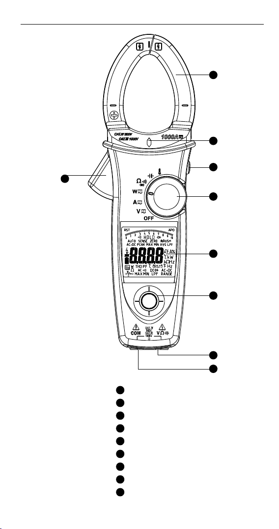
ACD-50 Series CAT IV Navigator Clamps Series
1
2
4
3
5
6
7
Jaw
1
Voltsense Light
2
Trigger
3
Hold / DCA Zero Key
4
Rotary Switch
5
Display
6
Navigator Key
7
V / / Input
8
Common Input
9
8
9
Page 6

CONTENTS
SYMBOLS ........................................................................................................ 1
UNPACKING AND INSPECTION ...................................................................... 2
FEATURES ........................................................................................................ 2
OPERATION ..................................................................................................... 3
Making Basic Measurement ...................................................................... 4
Measuring Voltage ..................................................................................... 5
Measuring Current ..................................................................................... 6
Auto Sense Mode ....................................................................................... 7
Peak Hold ................................................................................................... 7
Inrush Current ............................................................................................ 8
DC A ZERO .................................................................................................. 9
Measuring Frequency ................................................................................ 9
MAX/MIN/AVG ............................................................................................ 9
THD Measurement ..................................................................................... 10
LPF ............................................................................................................... 11
Measuring Active Power (W) / Power factor (PF) ..................................... 12
Phase Rotation ........................................................................................... 14
OHM Measurements .................................................................................. 15
Measuring Capacitance ............................................................................. 16
Measuring Temperature °C / °F ................................................................. 17
Measuring μA Current ............................................................................... 18
AUTO / Manual Range ............................................................................... 19
HOLD Key ................................................................................................... 19
VoltSense .................................................................................................... 20
Buzzer ......................................................................................................... 20
Power-up Option........................................................................................ 20
Battery State Display .................................................................................. 20
SPECIFICATION ................................................................................................21
MAINTENANCE AND REPAIR ......................................................................... 27
Trouble Shooting........................................................................................27
Cleaning and Storage ................................................................................ 27
Battery Replacement ................................................................................. 27
Page 7

SYMBOLS
Caution ! Risk of electric
shock
Application around and
removal from hazardous live
conductors is permitted.
Alternating Current (AC).
Temperature Measurement
Capacitance Measurement
Continuity Beeper
To alert you to the presence
of a potentially hazardous
voltage, when the Meter
detects a voltage ≧30 V or a
voltage overload (OL) in V.
This symbol is displayed.
Conform to relevant
Australian standards
Do not dispose of this product as unsorted municipal waste.
Contact a qualified recycler
Caution ! Refer to the
explanation in this Manual
Equipment protected
by double or reinforced
insulation
Direct Current (DC).
Resistance Measurement
Diode Measurement
Earth (Ground)
Complies with European
Directives
Battery
Safety Information
• Individual protective equipment should be used if HAZARDOUS LIVE
parts in the installation where measurement is to be carried out
could be ACCESSIBLE
• This manual contains information and warnings that must be
followed for operating the instrument safely and maintaining the
instrument in a safe operating condition. If the instrument is used in
a manner not specified by the manufacturer, the protection provided
by the instrument may be impaired.
• The meter is intended only for indoor use.
• The meter protection rating, against the users, is double insulation
per IEC/EN 61010-1 3rd Ed, Category III 1000 Volts AC & DC and
Category IV 600 Volts AC & DC.
• Disconnect the test leads from the test points before changing the
position of the function rotary switch.
• Never connect a source of voltage with the function rotary switch in
, , , μA, position.
• Do not expose Meter to extremes in temperature or high humidity.
• Never set the meter in
of a power supply circuit in equipment that could result in damage
the meter and the equipment under test.
, , , μA, function to measure the voltage
1
Page 8

Measurement category:
V : Category III 1000 Volts AC & DC, and Category IV 600 Volts AC & DC.
A : Category III 1000 Volts AC & DC, and Category IV 600 Volts AC & DC.
Per IEC 61010-1 3rd Ed. Measurement Category
Measurement Category IV (CAT IV) is for measurements performed at the
source of the low-voltage installation. Examples are electricity meters and
measurements on primary overcurrent protection devices and ripple control
units.
Measurement Category III (CAT III) is for measurements performed in
the building installation. Examples are measurements on distribution
boards, circuit- breakers, wiring, including cables, bus-bars, junction
boxes, switches, socket-outlets in the fixed installation, and equipment for
industrial use and some other equipment, for example, stationary motors
with permanent connection to the fixed installation.
WARNING
To reduce the risk of fire or electric shock, do not expose this product to
rain or moisture. To avoid electrical shock hazard, observe the proper
safety precautions when working with voltages above 60 VDC or 30 VAC
rms. These voltage levels pose a potential shock hazard to the user. Do not
touch test lead tips or the circuit being tested while power is applied to the
circuit being measured. Keep your fingers behind the finger guards of the
test leads during measurement. Inspect test leads, connectors,
and probes for damaged insulation or exposed metal before using the
instrument. If any defects are found, replace them immediately. Only use
the accompanied test leads, or replace with the same rating or better.
UNPACKING AND INSPECTION
Your shipping carton should include:
1 Power clamp meter
1 Test leads (1 pair)
1 Temp. adapter and probe (for ACD-51NAV and ACDC-54NAV only)
1 Users Manual
1 Carrying case
1 9V alkaline battery (installed)
If any of the items are damaged or missing, return the complete package to
the place of purchase for an exchange.
FEATURES
• True RMS
• Measurements:
o Voltage up to 1000V AC/DC, Resistance, Frequency, THD (Total
Harmonics Distortion) and Individual Harmonics 1 to 25, Power,
Power Factor
o AC Current
- Up to 600A (ACD-50NAV, ACD-51NAV, ACDC-52NAV)
- Up to 1000A (ACD-53NAV, ACDC-54NAV)
2
Page 9
o DC Current
- Up to 600A (ACDC-52NAV)
- Up to 1000A (ACDC-54NAV)
o Capacitance
o Temperature Measurement in °C / °F (ACD-51NAV, ACDC-54NAV
only) - Temp. adapter and probe included
o DC Micro Amps (ACD-51NAV only)
• Phase Rotation Indication
• Non-contact voltage detection
• Inrush Current measurement for motors
• Low Pass Filter for variable frequency drives
• Continuity Beeper
• Min, Max and Smart Data Hold
• Peak Hold
• Auto torch-light when clamping
• Large 10000 count display with active backlight and analog Bar graph
• Auto Power Off
• Maximum Jaw Opening 1.77” (45mm)
• 4 feet Drop Proof
• Deluxe Carrying Case Included
• CAT IV 600V /CAT III 1000V Safety Standard
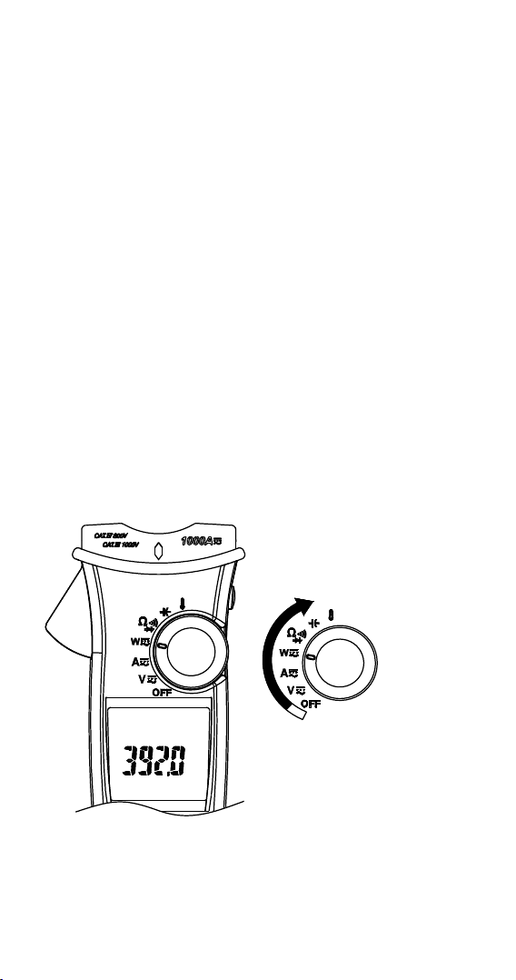
OPERATION
Power On / Off
3
Power on
Page 10

Auto Power Off
After idle 15 min
The meter can work again by turning it on from the OFF position.
Auto Power Off (APO) disable : Press “Downward” of Navigator key while
tuning meter on from OFF position.
Navigator Key
UP
LEFT
ENTER
RIGHT
DOWN
The Navigator Key has 5 directions of switch on the display, toggle the
navigator key to select the desired feature to activate the feature by a
simple click.
Making Basic Measurements
CAUTION
Before and after hazardous voltage measurements, test the voltage
function on a known source such as line voltage to determine proper meter
functioning.
When connecting the test leads to the EUT (Equipment Under Test) connect
the common test lead before connecting the live lead; when removing the
test leads, remove the test live lead before removing the common test lead.
4
Page 11
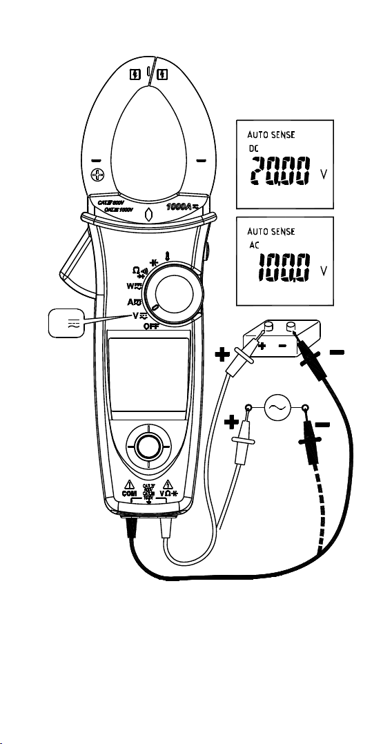
Measuring Voltage
V
WARNING
To avoid electrical shock, hazard or damage to meter, do not attempt to
measurement that might exceed 1000 V DC or AC RMS. Do not apply more
than 1000 V DC or AC RMS to the input terminals.
Note - If the measured voltage is higher than 30 V DC or AC RMS, the
display will show “
” symbol.
5
Page 12

Measuring Current
I
CAT IV 600V, CAT III
1000V with respect to
earth for the jaw. Tactile
Barrier for hand guard.
Do not hold the
meter across the Tactile
Barrier.
I
OK
I
OK
- Don’t clamp on any conductor while the meter power on.
- ACD-50NAV, ACD-51NAV or ACD-53NAV has only AC current
measurement mode.
- Torch lighting when clamping.
CAUTION
Please do not measure current from clamp jaw when temperature probe is
connected to meter.
6
I
I
OK
I+(-I)=0
Page 13

AUTO SENSE mode:
Display measurement result at AC only with RMS value or DC value, it
depends on whichever is greater.
AC mode: AC only with RMS value.
DC mode: DC value.
AC+DC mode: AC+DC RMS value.
Note:
• Select “ AC”, “ DC” or “ AC+DC” indicator then press the navigator
key to enter the AC/DC/AC+DC mode.
• Select “ AC”,” DC” or “ AC+DC” indicator then press the navigator
key for more than 2 seconds to return to the AUTO SENSE mode.
PEAK HOLD (AC mode only)
1. In ACV mode, select “ ” indicator on the display to enter PEAK
HOLD mode. To exit PEAK HOLD mode, press the navigator key for
more than 2 seconds.
"ENTER"
>2SEC
2. In AC A mode, select “ ” indicator then press the navigator key for
more than 2 seconds to enter PEAK HOLD mode. To exit PEAK HOLD
mode, just press the navigator key for more than 2 seconds to return
to the “
” indicator.
>2SEC
"ENTER"
>2SEC
7
Page 14
In PEAK HOLD mode, the meter is activated to save the positive peak value
and negative peak value. Positive peak value is displayed in PEAK MAX
mode. Negative peak value is displayed in PEAK MIN mode.
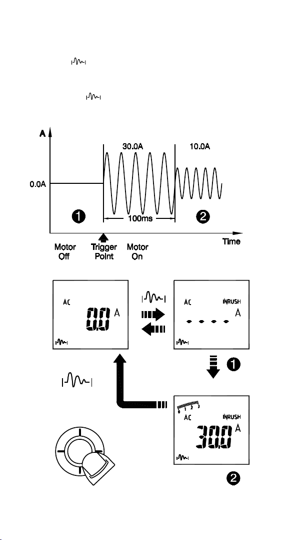
Inrush Current : (AC mode only)
If the under testing inrush current could be bigger than 100A ac, please
select the range to 600A/1000A in advance before activating inrush current.
In ACA mode, select “
mode. To exit Inrush Current mode, press the navigator key again.
” indicator on the display to enter Inrush Current
Loading
ENTER
Inrush current reading
8
Page 15
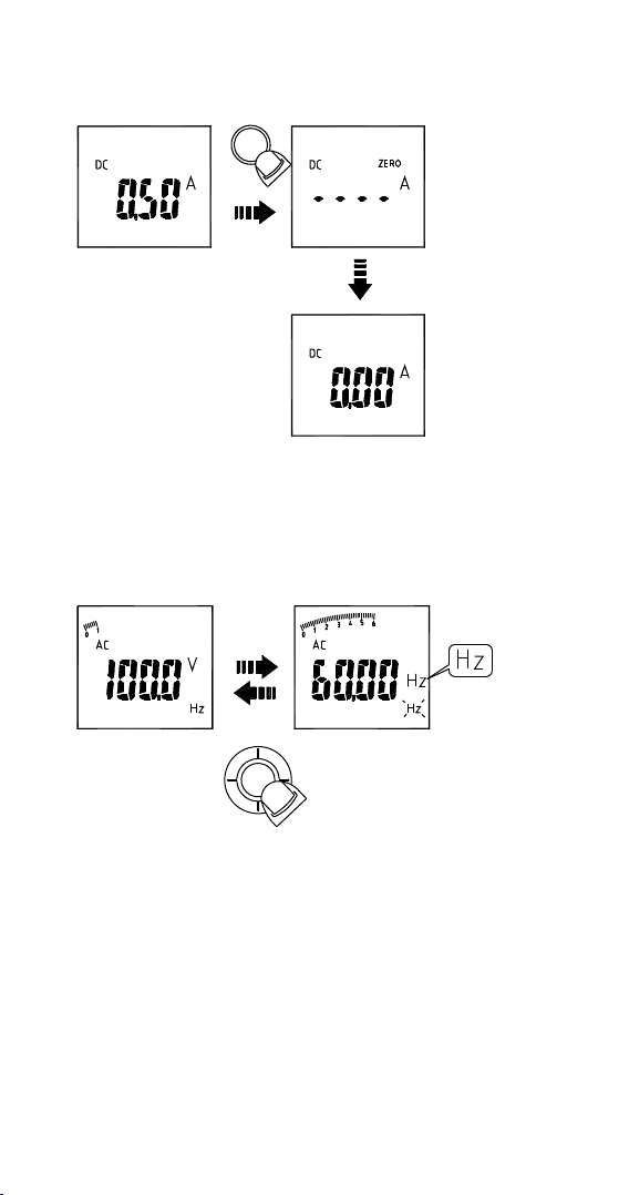
DC A ZERO (For ACDC-52NAV, ACDC-54NAV Only)
Remove the jaw out of the conductor.
Press HOLD Key > 2 seconds to compensate the residual magnetism.
HOLD> 2 Sec
HOLD
- DC A Zero is only available in Auto Sense, DC and AC+DC mode.
Measuring Frequency (AC mode only)
Select the “Hz” indicator then press the navigator key to enter/exit the
frequency measurement mode.
"Hz"
ENTER
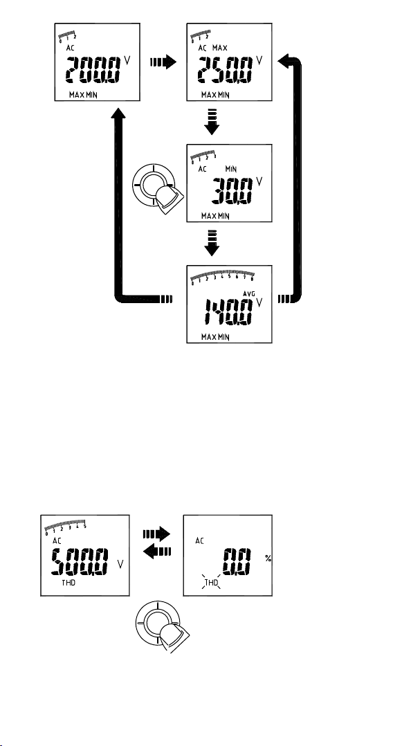
MAX/MIN/AVG
Select the “MAX MIN” indicator then press the navigator key to enter the
MAX/MIN/AVG mode. To quit from the MAX/MIN/AVG mode, press the
navigator key for more than 2 seconds.
The MAX/MIN/AVG mode records the minimum and maximum input
values. When the inputs go below the record minimum value or above the
record maximum value, the meter records the new value. The MAX/MIN/
AVG mode can also calculate the average of the maximum value and the
minimum value.
9
Page 16
"MAXMIN"
"MAXMIN"
ENTER
MAXMIN >2sec
"MAXMIN"
"MAXMIN"
Note :
• Press HOLD key in MAX MIN mode to make the meter stop updating
the maximum and minimum value. When the HOLD mode is
activated in MAX MIN mode, the HOLD mode must be deactivated
before the MAX MIN mode.
THD Measurement (AC mode only)
Select the “THD” indicator then press the navigator key to enter the THD
mode. THD-F=RMS of Harmonics ÷ RMS of fundamental ×100%. (harmonics
up to the 25th)
"THD"
"ENTER"
10
Page 17

Individual Harmonic Measurement (AC mode only)
Select the “ “ indicator then press the navigator key to enter the
individual harmonic mode. To quit from the individual harmonic mode,
press the navigator key for more than 2 seconds.
Hn=RMS of Individual Harmonic ÷ RMS of fundamental ×100%.
" "
>2SEC
ENTER
" "
"RIGHTWARD"
"LEFTWARD"
"UPWARD"
"DOWNWARD"
"RIGHTWARD"
"LEFTWARD"
"UPWARD"
"DOWNWARD"
LPF (AC mode only)
Select the “LPF” indicator then press the navigator key to eliminate high
frequency noise
"LPF"
ENTER
Note : Peak Hold, Inrush, THD, HZ, individual Harmonic and LPF mode are
only available in AC mode.
11
Page 18
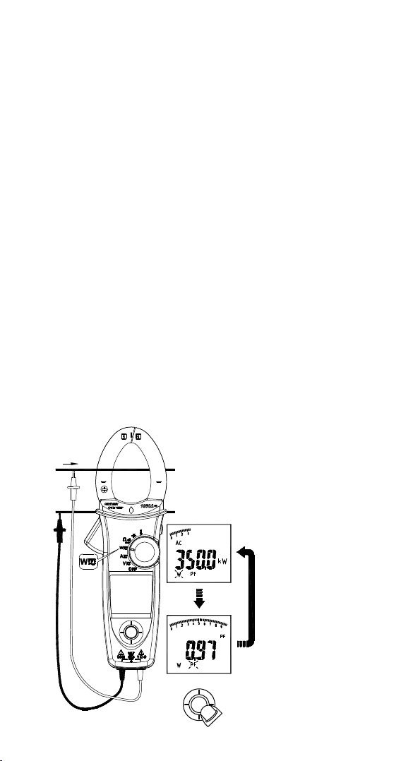
Measuring Active Power (W) / Power factor (PF)
1. Single Phase Power Measurement
Step1. Set the rotary switch to the “W” position.
Step2. Connect the Red test lead to the Line conductor, and the Black
test lead to the Neutral conductor.
Step3. Press the trigger to open the transformer jaws and clamp one
conductor only, make sure that the jaw is firmly closed around the
conductor.
Step4. Using the Navigator key to choose the “W/PF” mode.
Note :
• The “ + ” symbol on the jaw must face on the power source side.
• In AutoSense mode, the meter will displays ACW/DCW depends on if
there is AC frequency detected.
• ACD-50NAV, ACD-51NAV and ACD-53NAV offer AC power
measurement mode only.
Active power sign :
No sign : Indicates the power flows from the power source to the load.
“_” sign : Indicates the power flows from the load to the power source.
Power factor sign :
No sign : The phase of the current signal is lagging behind the voltage
signal (inductive load).
“_” sign : The phase of the current signal is leading the voltage signal
(capacitive load).
Overrange display :
OL.U : Voltage overload
OL.A : Current overload
OL.UA : Both Voltage and current overload.
± OL kW : Active Power > 1000 kW or < -1000 kW.
600V
600A
+L
-N
"PF"
ENTER
"W"
12
Page 19

2.Three Phase Power Measurement
A. 3 phase 3 wire balanced / unbalanced
Step 1. Set the rotary switch to the “W” position
Step 2. Using the Navigator key to choose the “W” mode.
Black
W=W1+W2
2
Red
Red
Black
1
3
Wye or star
B. 3 phase 4 wire balanced / unbalanced
Step1. Set the rotary switch to the “W” position
Step2. Using the Navigator key to choose the “W” mode.
W=W1+W2+W3
N
1
2
3
Black
Red
Black
Black
Red
Red
13
Page 20
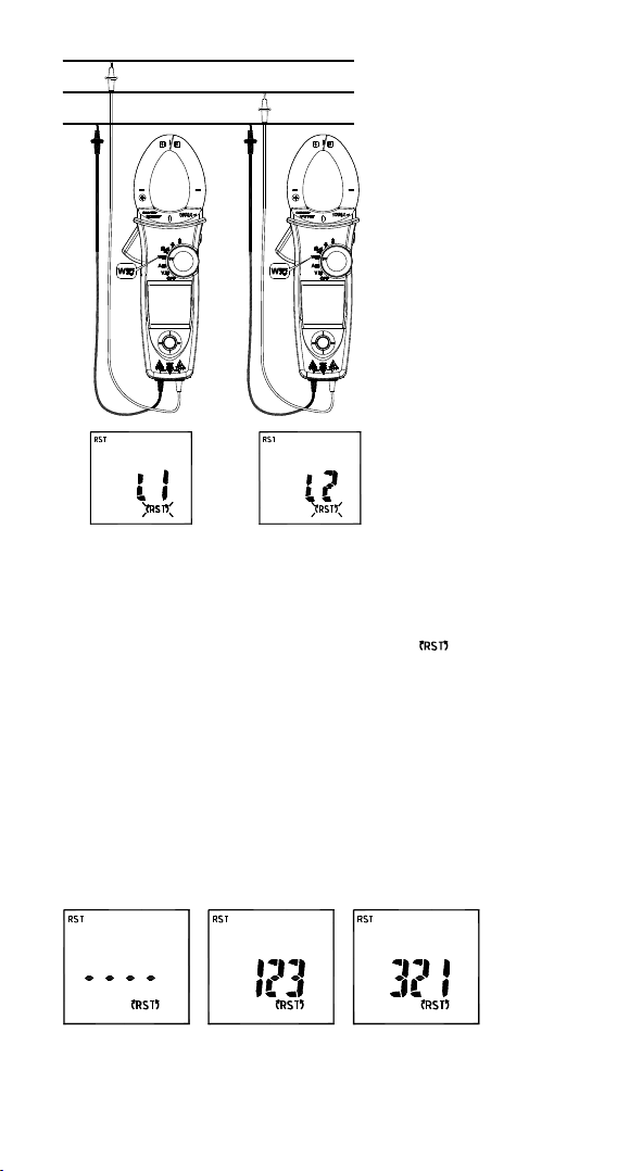
Phase Rotation
Line 1
Line 2
Line 3
Note :
• Connect three phase of power source as shown above.
• The test is only available while the system frequency is stable.
Step 1. Set the rotary switch to the “W” position.
Step 2. Using the Navigator key to choose the “
Step 3. Connect the Red test lead and Black test lead to any of the
line conductor (e.g. Red test lead to the phase Line 1, and Black test
lead phase Line 3).
Note: If the followings occur, the meter will not be able to
determine the line phase:
The screen displays “OLU” and blinking: voltage > 1000V
The screen displays “LoU” and blinking: voltage < 30V
The screen displays “outF” and blinking: frequency > 65Hz or < 45Hz
Step 4. When the BUZZER beeps twice, change one of the test lead
to another line conductor within 3 seconds
The screen will display the result as below:
“ mode
a) If it displays “ 1 2 3 “, then the phase sequence is forward
sequence
b) If it displays “ 3 2 1 ”, then the phase sequence is reversed
sequence
14
Page 21

c) When displayed “- - - - “ means it is unable to determine line
phases.
d) If it displays “LoU”, it is possible that you remove the test leads
before the meter completing its testing procedures.
Step 5. To repeat the test, using the Navigator key and choose the
“
“ mode again.
OHM Measurement
CAUTION
To avoid possible damage to the Meter or to the equipment under test,
disconnect circuit power and discharge all high-voltage capacitors before
measuring resistance and diode.
Note:
• Select
/ / indicator then press the navigator key to enter the
/ / mode.
/ / indicator then press the navigator key for more
• Select
than 2sec to return to the AUTO SENSE mode.
Note: Under diode mode: when the screen displays “bad” when
measuring a diode, the diode may have been damaged.
15
Page 22
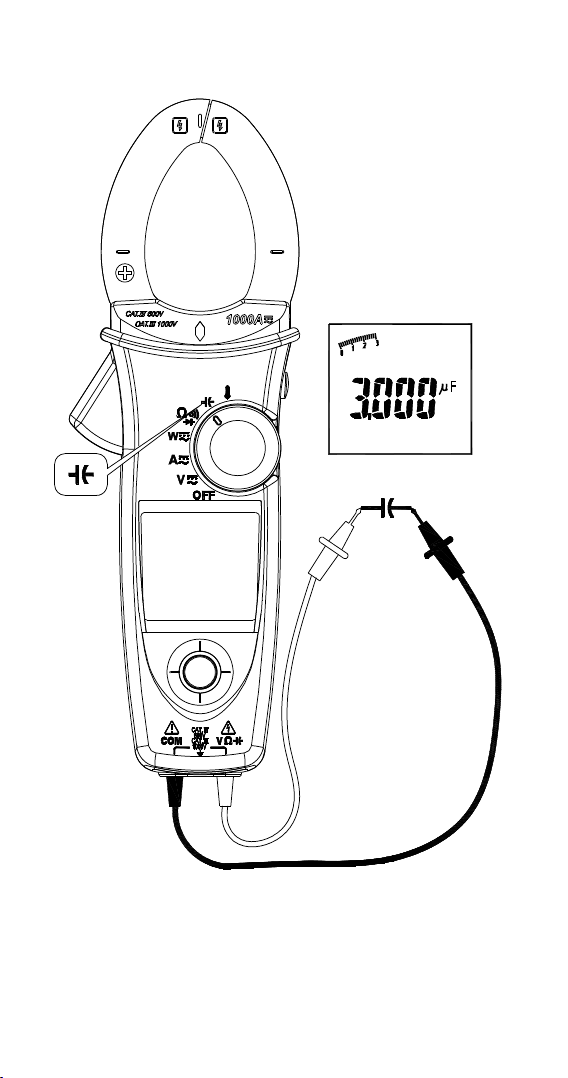
Measuring Capacitance
Set the rotary switch to the ““ position.
Capacitance
CAUTION
To avoid possible damage to the meter or to the equipment under test,
disconnect circuit power and discharge all high-voltage capacitors before
measuring capacitance. Use the DC voltage function to confirm that the
capacitor is discharged.
Note: The meter will display “diSC” while discharging the capacitor.
16
Page 23
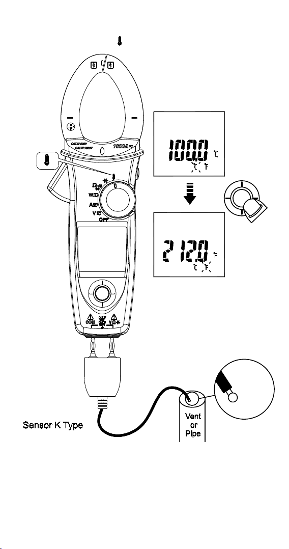
Measuring Temperature °C / °F
( For ACD-51NAV and ACDC-54NAV Only)
Set the rotary switch to the “ ” position.
"°F"
ENTER
Don’t take any high voltage measurement prior to accurate °C/°F
measurements.
17
Page 24

Measuring μA Current (For ACD-51NAV Only)
Set the rotary switch to the μA position.
Disconnect
18
Page 25
Other Function :
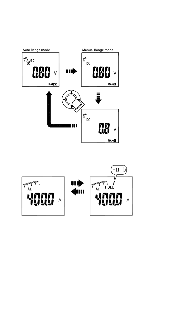
AUTO/MANUAL Range
Select the “RANGE“ indicator, then press the navigator key to enter the
manual range mode. To return to the auto range mode, press the navigator
key for more than 2 seconds.
"Range"
"ENTER"
"Range"
"Range"
>2SEC
HOLD Key
Press HOLD key to freeze display value.
Press
Hold key
SMART HOLD: The meter will beep continuously and the display will flash if
the measured signal is larger than the display reading. (for V.A.W function)
19
Page 26
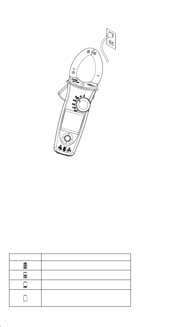
VoltSense
The red diamond shape of LED will illuminate, if there has electric field
been detected from the jaw.
Buzzer
The Meter beeps once for every valid key-press, and beeps twice for every
invalid key-press.
Power-up options
Press one of the following keys while turning meter on from OFF position.
Upward of Navigator key: Display of the software version.
Downward of Navigator key: Disable auto power off.
Leftward of Navigator key: Disable active backlight.
HOLD KEY: Display all LCD symbols approx 10 seconds.
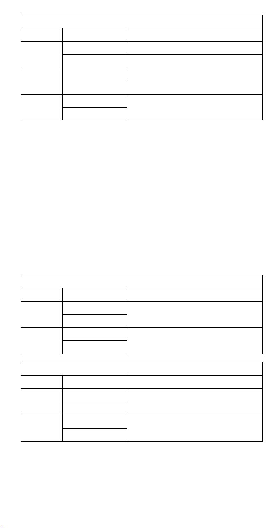
Battery State display
User can know the battery state from the battery indicator
Batter State Description
The battery is fully charged
The battery is remained 2/3 power
The battery is remained 1/3 power
Replace the battery as soon as the low
battery indicator appears, to avoid
inaccurate reading.
Refer to MAINTENANCE AND REPAIR section for battery replacement.
20
Page 27

SPECIFICATIONS
General Specications
Display count : 10000 or 4000
Measuring rate : 3 times / per second
Overrange display : “OL” or “-OL” .
Auto Power Off : Approx. 15 minutes.
Low battery indicator :
indicator appears in the display.
Power requirement : 9V battery.
Battery life : ALKALINE 9V 50 hours (without Backlight).
is displayed. Replace the battery when the
Environmental Conditions
Indoor Use
Calibration: One year calibration cycle.
Operating temperature: 0 °C ~ 10 °C
11 °C ~ 30 °C (≦80% RH)
30 °C ~ 40 °C (≦75% RH)
40 °C ~ 50 °C (≦45%RH)
Storage temperature: -10 to 50 °C for current,
-20 to 60 °C for other function,
0 to 80% RH (batteries not fitted).
Temperature coefcient: 0.2 x (Specified accuracy) / °C, < 18°C, > 28°C .
Over voltage category: CAT IV 600 V, CAT III 1000 V : IEC61010-2-030 and
61010-2-032
CAT Application eld
I The circuits not connected to mains.
II The circuits directly connected to Low-voltage installation.
III The building installation.
IV The source of the Low-voltage installation.
CENELEC Directives: The instrument conforms to CENELEC Low-voltage
directive 2006/95/EC and Electromagnetic compatibility directive 2004/108/
EC.
Safety Compliance:
- IEC/EN 61010-1 Ed. 3.0, UL 61010-1(2nd Ed.), CAN/CSA-C22.2 No.610101-04 to Measurement Category III 600 V, Pollution Degree 2
- IEC/EN 61010-2-030
- IEC/EN 61010-2-032, CAN/CSA-C22.2 No.61010-2-032-04
- IEC/EN 61010-031 (test leads)
EMC: meets all applicable requirements in IEC/EN 61326-1
Operating altitude: up to 2000m (6562 ft)
Conductor Size:
37mm diameter for ACD-50NAV, ACD-51NAV, ACDC-52NAV
42mm diameter for ACD-53NAV, ACDC-54NAV
Shock vibration: Sinusoidal vibration per MIL-T- 28800E (5 ~ 55 Hz, 3g
maximum).
Drop Protection: 4 feet drop to hardwood on concrete floor.
21
Page 28

Electrical Specications
Accuracy is ±(% reading + number of digits) at 23°C ± 5°C < 80%RH.
(1) Voltage
ACD-50NAV, ACD-51NAV, ACDC-52NAV, ACD-53NAV, ACDC-54NAV
Function Range Accuracy*
DC V
AC V
LPF
* DCV <1000dgt, add 6 dgt to the accuracy. ACV <1000dgt, add 3 dgt to the
accuracy.
Overload protection: 1000Vrms
Input Impedance: 3.5M // <100pF
AC Conversion Type: AC Conversions are ac-coupled, true RMS responding,
calibrated to the RMS value of a sine wave input. Accuracies are given for
sine wave at full scale and nonsine wave below half scale. For non-sine
wave (50/60Hz) add the following Crest Factor corrections:
For Crest Factor of 1.4 to 2.0, add 1.0% to accuracy.
For Crest Factor of 2.0 to 2.5, add 2.5% to accuracy.
For Crest Factor of 2.5 to 3.0, add 4.0% to accuracy.
CF 3 @ 460V,460A (for ACD-53NAV, ACDC-54NAV),
280A (for ACD-50NAV, ACD-51NAV, ACDC-52NAV)
2 @ 690V, 690A (for ACD-53NAV, ACDC-54NAV),
420A (for ACD-50NAV, ACD-51NAV, ACDC-52NAV)
AC+DC Vrms Accuracy: same as ACV spec. +DCV spec.
99.99V
999.9V
99.99V
999.9V
99.99V
999.9V
± (0.7% + 2dgt)
± (1.0% + 5dgt)
50 ~ 500Hz
50 ~ 60Hz ± (1% + 5dgt)
61 ~ 400Hz ± (5% + 5dgt)
(2) Current
ACD-50NAV, ACD-51NAV, ACD-53NAV
Function Range Accuracy
AC A
LPF
AC A
* ACD-50NAV, ACD-51NAV: 599.9A; ACD-53NAV : 999.9A
** The measured value <1000dgt, add 5 dgt to the accuracy.
99.99A
599.9A / 999.9A*
0.10A ~ 99.99A
599.9A / 999.9A*
50 ~ 60Hz ± (1.5% + 5dgt) **
61 ~ 400Hz ± (2% + 5dgt) **
50 ~ 60Hz ± (1.5% + 5dgt) **
61 ~ 400Hz ± (5% + 5dgt) **
22
Page 29
ACDC-52NAV, ACDC-54NAV
Function Range Accuracy
DC A
AC A
LPF
AC A
* ACDC-52NAV: 599.9A ; ACDC-54NAV: 999.9A
** The measured value <1000dgt, add 5 dgt to the accuracy.
Overload protection: 1000Arms For ACD-53NAV, ACDC-54NAV
600Arms For ACD-50NAV, ACD-51NAV, ACDC-52NAV
Position Error: ±1% of reading.
AC Conversion Type and additional accuracy is same as AC Voltage.
AC+DC Arms Accuracy: Same as ACA spec + DCA spec.
• For better measurement accuracy of high current, do not
measurement more than 10 minutes (for ACD-50NAV, ACD-51NAV,
ACD-53NAV)
• DC A affected by the temperature and the residual magnetism.
Press HOLD key > 2 seconds to compensate it.
(3) Peak Hold : Peak MAX / Peak MIN
Function Range Accuracy
AC V
AC A
99.99A ± (1.5% + 0.2A)
599.9A / 999.9A* ± (1.5% + 5dgt) **
0.10A ~ 99.99A
599.9A / 999.9A*
0.10A ~ 99.99A
599.9A / 999.9A*
ACD-50NAV, ACD-51NAV, ACDC-52NAVV
140.0V
1400V
140.0A
850A
50 ~ 60Hz ± (1.5% + 5dgt) **
61 ~ 400Hz ± (2% + 5dgt) **
50 ~ 60Hz ± (1.5% + 5dgt) **
61 ~ 400Hz ± (5% + 5dgt) **
± (3.0% + 15dgt)
± (3.0% + 15dgt)
ACD-53NAV, ACDC-54NAV
Function Range Accuracy
AC V
AC A
Overload protection: 1000 Vrms
600 Arms For ACD-50NAV, ACD-51NAV, ACDC-52NVA
1000 Arms For ACD-53NAV, ACDC-54NAC
Accuracy dened for:
Sine wave, ACV>5Vrms / ACA
• Only suitable for the repetitive events.
140.0V
1400V
140.0A
1400A
± (3.0% + 15dgt)
± (3.0% + 15dgt)
≧5Arms, Freq. 50~400Hz.
23
Page 30
(4) Frequency
ACD-50NAV, ACD-51NAV, ACDC-52NAV, ACD-53NAV, ACDC-54NAV
Function Range Accuracy
20.00 ~ 99.99Hz
Frequency
0.020 ~ 9.999KHz
Overload protection : 1000 Vrms
600 Arms For ACD-50NAV, ACD-51NAV, ACDC-52NAV
1000 Arms For ACD-53NAV, ACDC-54NAV
Sensitivity :
10~100Vrms for AC 100V range
10~100Arms for AC 100A range ( >400Hz Unspecified)
100~1000Vrms for AC 1000V range
100~600/1000Arms for AC 600A/1000A range ( >400Hz Unspecified)
- Reading will be 0.0 for signals below 10.0 Hz.
(5) Total Harmonic Distortion:
ACD-50NAV, ACD-51NAV, ACDC-52NAV, ACD-53NAV, ACDC-54NAV
Function Range Accuracy
AC A / AC V 99.9% ± (3.0% + 10dgt)
Harmonic distortion measurement:
ACD-50NAV, ACD-51NAV, ACDC-52NAV, ACD-53NAV, ACDC-54NAV
Harmonic order Range Accuracy
H01 ~ H12
H13 ~ H25 ± (10% + 10dgt)
Overload protection: 1000 Vrms
600 Arms For ACD-50NAV, ACD-51NAV, ACDC-52NAV
1000 Arms For ACD-53NAV, ACDC-54NAV
• If ACV<10Vrms or ACA <10Arms, it will display “rdy”.
• If the fundamental frequency out of range 45 ~ 65Hz, it will display
“out.F”.
99.9%
± (0.5% + 3dgt)20.0 ~ 999.9Hz
± (5% + 10dgt)
(6) Inrush Current:
ACD-50NAV, ACD-51NAV, ACDC-52NAV, ACD-53NAV, ACDC-54NAV
Function Range Accuracy
AC A
* ACD-50NAV, ACD-51NAV, ACDC-52NAV: 599.9A
ACD-53NAV, ACDC-54NAV : 999.9A
99.99A ± (2.5% + 0.2A)
599.9A / 999.9A * ± (2.5% + 5dgt)
24
Page 31

Overload protection: 1000 Vrms
600 Arms For ACD-50NAV, ACD-51NAV, ACDC-52NAV
1000 Arms For ACD-53NAV, ACDC-54NAV
Accuracy dened for:
Sine wave, ACA
- Integration time about 100m seconds
(7) Active Power : Watt (DC/AC)
ACD-50NAV, ACD-51NAV, ACDC-52NAV, ACD-53NAV, ACDC-54NAV
Function Range Accuracy
AC W / DC W
* ACD-50NAV, ACD-51NAV, ACDC-52NAV: 599.9KW
ACD-53NAV, ACDC-54NAV: 999.9KW
** The measured value<1.000kW, add 10 dgt to the accuracy.
Overload protection : 1000 Vrms
600 Arms For ACD-50NAV, ACD-51NAV, ACDC-52NAV
1000 Arms For ACD-53NAV, ACDC-54NAV
Accuracy dened for :
AC W :
Sine wave , ACV
Freq. 50~60Hz, PF=1.00
DCW (For ACDC-52NAV, ACDC-54NAV only) :
≧ 10V, DCA ≧ 5 A
DCV
≧10Arms, Freq. 50/60Hz
9.999KW**
99.99KW
599.9KW / 999.9KW*
≧ 10 Vrms, ACA≧ 5 Arms
A,error×V,reading+
V,error×A,reading
(8) Power Factor:
ACD-50NAV, ACD-51NAV, ACDC-52NAV, ACD-53NAV, ACDC-54NAV
Function Range Accuracy*
PF -1.00 ~ 0.00 ~1.00 ±3°±1dgt
* ACA<100A, add ±2° to the accuracy (For ACD-50NAV, ACD-51NAV, ACD53NAV)
Overload protection : 1000 Vrms
600 Arms For ACD-50NAV, ACD-51NAV, ACDC-52NAV
1000 Arms For ACD-53NAV, ACDC-54NAV
25
Page 32

(9) Resistance & Continuity & Diode:
ACD-50NAV, ACD-51NAV, ACDC-52NAV, ACD-53NAV, ACDC-54NAV
Function Range Accuracy
999.9 ± (1.0% + 5dgt)
Resistance
Continuity 999.9 ± (1.0% + 5dgt)
Diode 0.40 ~ 0.80V ± 0.1V
Overload protection : 1000Vrms
Max. Test Current : Approx. 0.5mA.
Maximum Open Circuit Voltage for ,
Maximum Open Circuit Voltage for diode : Approx. ±1.8V
Continuity check :
Continuity Threshold: <30 ohm Beep On.
<100 ohm Beep Off.
Continuity Indicator : 2 KHz Tone Buzzer
(10) Capacitance:
ACD-50NAV, ACD-51NAV, ACDC-52NAV, ACD-53NAV, ACDC-54NAV
Function Range Accuracy
Capacitance
Overload protection : 1000Vrms
9.999 k
99.99 k
3.999 μF
39.99 μF
399.9 μF
3999 μF
± (1.0% + 3dgt)
Approx. 3V
± (1.9% + 8dgt)
(11) Temperature :
ACD-51NAV, ACDC-54NAV
Function Range Accuracy
-50 °C ~ 99.9 °C ± (1% + 2°C)
°C
°F
Overload protection : 1000 Vrms
• The above specication is assumed at the ambient temperature
stability within ±1°C. In addition, the temperature probe has
to be connected to meter for more than 1 hour before taking
measurement.
• The meter needs 2 hours for stability for ambient temperature
variation more than ±5°C.
100 °C ~ 399.9 °C
400 °C ~ 1000 °C
-58 °F ~ 211.9 °F ± (1% + 4°F)
212.0 °F ~ 751.9 °F
752 °F ~ 1832 °F
± (1% + 1°C)
± (1% + 2°F)
26
Page 33

(12) DC μA :
ACD-51NAV
Function Range Accuracy
DCμA 999.9 μADC ± (1.7% + 2dgt)*
*<1000dgt, add 3 dgt to the accuracy.
Overload protection : 1000 Vrms
MAINTENANCE AND REPAIR
CAUTION
To avoid electrical shock, disconnect the meter from any circuit, remove the
test leads from the input jacks and turn OFF the meter before opening the
case. Do not operate with open case. Install only the same type of battery
or equivalent
Trouble Shooting
If the instrument fails to operate, check battery, leads, etc., and replace
as necessary. Double check operating procedure as described in this user’s
manual. If the instrument voltage-resistance input terminal has subjected
to high voltage transient (caused by lightning or switching surge to the
system) by accident or abnormal conditions of operation, the series fusible
resistors will be blown off (become high impedance) like fuses to protect
the user and the instrument. Most measuring functions through this
terminal will then be open circuit. The series fusible resistors and the spark
gaps should then be replaced by qualified technician. Refer to the LIMITED
WARRANTY section for obtaining warranty or repairing service.
Cleaning and Storage
Periodically wipe the case with a damp cloth and mild detergent; do not
use abrasives or solvents. If the meter is not to be used for periods of
longer than 60 days, remove the battery and store it separately.
Battery Replacement
1. Remove test leads and turn the Meter OFF.
2. Loosen the screw from the battery access door of the case. Lift the
battery access door and thus the battery compartment up.
3. Replace the battery (9V alkaline battery NEDA1604A, JIS6AM6 or
IEC6LF22).
4. Put the battery access door back and re-fasten the screw.
27
Page 34

CAUTION
Remove test leads from Meter before opening the battery cover or Meter
case.
Page 35

ACD-50NAV
Pince de navigation 600 A c.a.
ACD-51NAV
Pince de navigation eff. vraie
600 A c.a.
ACDC-52NAV
Pince de navigation eff. vraie
600 A c.a. / c.c.
ACD-53NAV
Pince de navigation eff. vraie
1 000 A c.a.
ACDC-54NAV
Pince de navigation eff. vraie
1 000 A c.a. / c.c.
Français
Mode d’emploi
7/2013, Rév.2
©2013 Amprobe Test Tools.
Tous droits réservés. Imprimé à Taïwan.
Page 36

Limites de garantie et de responsabilité
Amprobe garantit l'absence de vice de matériau et de fabrication de ce produit pendant
une période d’un an à compter de la date d'achat. Cette garantie ne s'applique pas aux
fusibles, aux piles jetables ni à tout produit mal utilisé, modifié, contaminé, négligé
ou endommagé par accident ou soumis à des conditions anormales d'utilisation et de
manipulation. Les revendeurs n’ont pas l’autorisation de prolonger toute autre garantie
au nom d’Amprobe. Pour bénéficier de la garantie, renvoyez le produit accompagné
d'un justificatif d'achat auprès d'un centre de services agréé par Amprobe Test Tools ou
d’un distributeur ou d’un revendeur Amprobe. Voir la section Réparation pour tous les
détails. LA PRÉSENTE GARANTIE EST LE SEUL ET EXCLUSIF RECOURS DE L'UTILISATEUR
TOUTES AUTRES GARANTIES, EXPLICITES, IMPLICITES OU STATUTAIRES, NOTAMMENT
LE CAS ÉCHÉANT, LES GARANTIES DE QUALITÉ MARCHANDE OU D'ADAPTATION À
UN OBJECTIF PARTICULIER SONT EXCLUES PAR LES PRÉSENTES. LE FABRICANT NE
SERA EN AUCUN CAS TENU RESPONSABLE DE DOMMAGES PARTICULIERS, INDIRECTS,
ACCIDENTELS OU CONSÉCUTIFS, NI D'AUCUNS DÉGÂTS OU PERTES DE DONNÉES,
SUR UNE BASE CONTRACTUELLE, EXTRA-CONTRACTUELLE OU AUTRE. Etant donné
que certaines juridictions n'admettent pas les limitations d'une condition de garantie
implicite ou l'exclusion ou la limitation de dégâts accidentels ou consécutifs, il se peut
que les limitations et les exclusions de cette garantie ne s'appliquent pas à votre cas.
Réparation
Tous les outils de test renvoyés pour être réparés au titre de la garantie ou pour
étalonnage doivent être accompagnés des éléments suivants : nom, raison sociale,
adresse, numéro de téléphone et justificatif d’achat. Ajoutez également une brève
description du problème ou du service demandé et incluez les cordons de test avec
l’appareil. Les frais de remplacement ou de réparation hors garantie doivent être
acquittés par chèque, mandat, carte de crédit avec date d'expiration ou par bon de
commande payable à l'ordre de Amprobe® Test Tools.
Remplacements et réparations sous garantie – Tous pays
Veuillez lire la déclaration de garantie et vérifiez la pile avant de demander une
réparation. Pendant la période de garantie, tout outil de test défectueux peut être
renvoyé auprès de votre distributeur Amprobe® Test Tools pour être échangé contre
un produit identique ou similaire. Consultez la section « Where to Buy » sur le site
www.amprobe.com pour obtenir la liste des distributeurs dans votre région. Les
appareils sous garantie devant être remplacés ou réparés au Canada et aux États-Unis
peuvent également être envoyés dans un centre de services Amprobe® Test Tools (voir
les adresses ci-dessous).
Remplacements et réparations hors garantie – Canada et Etats-Unis
Les appareils à réparer hors garantie au Canada et aux États-Unis doivent être envoyés
dans un centre de services Amprobe® Test Tools. Appelez Amprobe® Test Tools ou
renseignez-vous auprès de votre lieu d’achat pour connaître les tarifs en vigueur de
remplacement ou de réparation.
Aux États-Unis Au Canada
Amprobe Test Tools Amprobe Test Tools
Everett, WA 98203 Mississauga, ON L4Z 1X9
Tél : 888-993-5853 Tél : 905-890-7600
Fax : 425-446-6390 Fax : 905-890-6866
Remplacements et réparations hors garantie – Europe
Les appareils européens non couverts par la garantie peuvent être remplacés par votre
distributeur Amprobe® Test Tools pour une somme nominale. Consultez la section
« Where to Buy » sur le site www.amprobe.com pour obtenir la liste des distributeurs
dans votre région.
Amprobe® Test Tools Europe
In den Engematten 14
79286 Glottertal, Allemagne
Tél : +49 (0) 7684 8009 - 0
*(Réservée à la correspondance – Aucune réparation ou remplacement n’est possible à
cette adresse. Nos clients européens doivent contacter leur distributeur.)
Page 37

ACD-50 Série CAT IV Pince de navigation
1
2
4
3
5
6
7
Mâchoire
1
Voyant de détection Voltsense
2
Gâchette
3
Touche de maintien / zéro A c.c.
4
Sélecteur rotatif
5
Affichage
6
Touche de navigation
7
Entrée V / /
8
Entrée du commun
9
8
9
Page 38

TABLE DES MATIÈRES
SYMBOLES ...................................................................................................... 1
DÉBALLAGE ET INSPECTION .......................................................................... 2
FONCTIONNALITÉS ......................................................................................... 2
FONCTIONNEMENT ........................................................................................ 3
Mesures de base ......................................................................................... 4
Mesures de tension .................................................................................... 5
Mesures de courant ................................................................................... 6
Mode de détection automatique (Auto Sense) ....................................... 7
Maintien de crête (Peak Hold) .................................................................. 7
Courant d'appel (Inrush) ........................................................................... 8
Zéro A c.c. (DC A ZERO) ............................................................................. 9
Mesure de fréquence (Hz) ......................................................................... 9
Min/Moy/Max (MAX/MIN/AVG) ................................................................. 9
Mesure du taux de distorsion harmonique (THD) ................................... 10
Faible facteur de puissance (LPF) .............................................................. 11
Mesure de la puissance active (W) / facteur de puissance (PF) ................ 12
Rotation de phases .................................................................................... 14
Mesures ohmiques ..................................................................................... 15
Mesure de capacité .................................................................................... 16
Mesure de température °C / °F .................................................................. 17
Mesure du courant μA ............................................................................... 18
Gamme AUTO / manuelle .......................................................................... 19
Touche de maintien HOLD......................................................................... 19
Détection de tension VoltSense ................................................................ 20
Avertisseur .................................................................................................. 20
Option au démarrage ................................................................................ 20
Affichage de l'état de pile ......................................................................... 20
CARACTÉRISTIQUES ....................................................................................... 21
ENTRETIEN ET RÉPARATION ........................................................................... 27
Dépannage ................................................................................................. 27
Nettoyage et entreposage ........................................................................ 27
Changement des piles ................................................................................ 27
Page 39

SYMBOLES
Attention ! Risque de
décharge électrique.
Son application et son retrait
à proximité de conducteurs
sous tension dangereuses
sont autorisés.
Courant alternatif (c.a.).
Mesures de température
Mesure de capacité
Avertisseur de continuité
Pour signaler la
présence d’une tension
potentiellement dangereuse
lorsque la pince détecte
une tension ≧30 V ou une
surcharge de tension (OL) en
V. Ce symbole apparaît.
Conforme aux directives de
l’association australienne de
normalisation
Ne pas mettre ce produit au rebut parmi les déchets ménagers.
Consulter un centre de recyclage homologué.
Attention ! Se reporter aux
explications de ce manuel.
Équipements protégés par
une isolation double ou
renforcée.
Courant continu (c.c.).
Mesure de résistance
Mesure de diode
Prise de terre
Conforme aux directives
européennes
Pile
Consignes de sécurité
• Un équipement de protection individuelle doit être utilisé si des
composants SOUS TENSION DANGEREUX dans l’installation risquent
d’être ACCESSIBLES là où la mesure doit être effectuée.
• Ce manuel présente les informations et les mises en gardes à
respecter pour assurer et maintenir un fonctionnement sans danger
de l’instrument. Cet appareil doit être utilisé de la manière spécifiée
par le fabricant afin de ne pas entraver la protection intégrée.
• La pince multimètre est destinée à être utilisée à l’intérieur
uniquement.
• La protection de la pince multimètre contre les manipulations
accidentelles est homologuée à double isolation IEC/EN 61010-1 3rd
Ed, Catégorie III 1 000 V c.a. et c.c. et catégorie IV
600 V c.a. et c.c.
• Débrancher les cordons de mesure des points de test avant de
changer de fonction sur le sélecteur rotatif.
• Ne jamais brancher une source de tension avec le sélecteur de
fonction en position
• Ne pas exposer la pince multimètre aux températures extrêmes ou à
une humidité élevée.
• Ne jamais régler la pince multimètre sur une fonction , , ,
μA pour mesurer la tension d’un circuit d’alimentation dans
l’équipement susceptible d’endommager la pince multimètre et
l’équipement testé.
, , , μA.
1
Page 40

Catégorie de mesure :
V : Catégorie III 1 000 V c.a. et c.c. et catégorie IV 600 V c.a. et c.c.
A : Catégorie III 1 000 V c.a. et c.c. et catégorie IV 600 V c.a. et c.c.
Selon CEI 61010-1 3e éd. Catégorie de mesure
La catégorie IV (CAT IV) de mesures concerne les mesures effectuées au
niveau de la source d’installation à basse tension. Il s’agit, par exemple
de compteurs électriques et des mesures effectuées sur les dispositifs
principaux de protection contre les surintensités et les unités de contrôle
des fluctuations.
La catégorie III (CAT III) de mesures concerne les mesures effectuées sur
les installations dans les bâtiments. Il s’agit, par exemple, des tableaux de
dérivation, des coupe-circuits, du câblage, y compris les conducteurs, les
barres omnibus, les boîtes de jonction, les commutateurs, les prises murales
de l’installation fixe, et le matériel destiné à l’utilisation industrielle, ainsi
que certains autres équipements tels que, par exemple, les moteurs fixes
connectés en permanence à l’installation fixe.
AVERTISSEMENT
Pour réduire le risque d’incendie ou d’électrocution, ne pas exposer
cet appareil à l’humidité ou à la pluie. Pour éviter les chocs électriques,
observer les précautions de sécurité appropriées en intervenant sur des
tensions supérieures à 60 V c.c. ou à 30 V c.a. eff. Ces niveaux de tension
présentent un risque d’électrocution pour l’utilisateur. Ne pas toucher à
l’embout des cordons de mesure ou au circuit testé quand l’électricité est
appliquée au circuit mesuré. Pendant la mesure, laisser les doigts derrière
les protections des cordons de test. Inspecter les cordons de mesure,
les connecteurs
et les sondes pour détecter tout endommagement éventuel de l’isolant ou
des parties métalliques exposées avant d’utiliser l’instrument. Remplacer
immédiatement l’élément si des défauts sont détectés. N’utiliser que les
cordons de mesure accompagnés, ou remplacer par des cordons de calibre
équivalent ou supérieur.
DÉBALLAGE ET INSPECTION
Le carton d’emballage doit inclure les éléments suivants :
1 pince multimètre de puissance
1 paire de cordons de mesure
1 sonde et adaptateur de température (ACD-51NAV et ACDC-54NAV
uniquement)
1 Users Manual
1 sacoche de transport
1 pile alcaline de 9 V (installée)
Si l’un de ces éléments est endommagé ou manquant, renvoyez le contenu
complet de l’emballage au lieu d’achat pour l’échanger.
FONCTIONNALITÉS
• Mesure efcace vraie
• Mesures :
o Tension jusqu’à 1 000 V c.a./c.c., résistance, fréquence, taux de
distorsion harmonique (THD) et taux individuel d’harmonique de
1 à 25, puissance, facteur de puissance
2
Page 41

o Courant c.a.
- Jusqu’à 600 A (ACD-50NAV, ACD-51NAV, ACDC-52NAV)
- Jusqu’à 1 000 A (ACD-53NAV, ACDC-54NAV)
o Courant continu
- Jusqu’à 600 A (ACDC-52NAV)
- Jusqu’à 1 000 A (ACDC-54NAV)
o Capacité
o Mesure de température en °C / °F (ACD-51NAV, ACDC-54NAV
uniquement) - Sonde et adaptateur de température inclus
o Microampères c.c. (ACD-51NAV uniquement)
• Indication de rotation des phases
• Détection de tension sans contact
• Mesure de courant d’appel pour les moteurs
• Filtre passe-bas pour les variateurs de vitesse
• Avertisseur de continuité
• Maintien des données minimum, maximum et intelligent
• Maintien de crête
• Lampe-torche automatique en travaillant avec la pince
• Grand afcheur de 10 000 comptes avec rétroéclairage actif et
graphique à barres analogiques
• Mise en veille automatique
• Mâchoire à 45 mm (1,77 po) d’ouverture maximum
• Résiste aux chutes d’une hauteur de 1,20 mètres (4 pieds)
• Mallette de transport de luxe incluse
• Norme de sécurité CAT IV 600 V/CAT III 1 000 V
FONCTIONNEMENT
Marche/arrêt
3
Sous tension
Page 42

Arrêt automatique
Après 15 mn d'inactivité
L’appareil peut fonctionner de nouveau par mise sous tension depuis la
position OFF.
Désactiver la mise en veille automatique (APO) : Appuyez sur la touche de
navigation « vers le bas » tout en ajustant la pince multimètre depuis la
position OFF.
Touche de navigation
HAUT
GAUCHE
ENTRER
DROITE
BAS
La touche de navigation offre 5 sens de commutation sur l’affichage ;
basculer la touche de navigation pour sélectionner la fonction souhaitée et
activer la fonction d'un simple clic.
Mesures de base
ATTENTION
Avant et après les mesures de tensions dangereuses, tester la fonction de
tension sur une source connue, une tension secteur p. ex., pour déterminer
le bon fonctionnement du multimètre.
En établissant les branchements des cordons de mesure aux équipements
testés, connecter le commun du cordon de mesure avant la polarité au
potentiel ; pour déconnecter les cordons de mesure, commencer par celui
au potentiel.
4
Page 43

Mesures de tension
V
AVERTISSEMENT
Pour éviter les chocs électriques, les dangers ou l’endommagement de
la pince multimètre, ne pas tenter de mesurer une tension au-delà de
1 000 V c.c. ou c.a. eff. Ne pas appliquer plus de 1 000 V c.c. ou c.a. eff. aux
bornes d’entrée.
Remarque : si la tension mesurée est plus élevée que 30 V c.c. ou c.a. eff.,
l’affichage indique le symbole «
».
5
Page 44

Mesures du courant
I
CAT IV 600 V, CAT III
1 000 V par rapport à la
terre pour la mâchoire.
Collerette de protection
de la main.
Ne pas tenir la
pince multimètre en
couvrant la collerette de
protection de la main.
I
OK
I
OK
- Ne serrez pas un conducteur à l’aide de la pince pendant la mise sous
tension de la pince.
- Les modèles ACD-50NAV, ACD-51NAV or ACD-53NAV n’ont qu’un mode
de mesure de courant alternatif.
- Lampe-torche automatique en travaillant avec la pince.
ATTENTION
Ne pas mesurer le courant de la mâchoire de la pince lorsque la sonde de
température est reliée à la pince.
6
I
I
OK
I+(-I)=0
Page 45

Mode de détection automatique (AUTO SENSE) :
Affiche le résultat de la mesure si c.a. uniquement avec valeur efficace ou si
valeur c.c. selon la valeur la plus grande.
Mode AC : c.a. uniquement avec valeur eff.
Mode DC : valeur c.c.
Mode AC+DC : valeur c.a.+ c.c. eff.
Remarque :
• Sélectionnez l’indicateur « AC », « DC » ou « AC+DC » et appuyez sur
la touche de navigation pour passer en mode AC/DC/AC+DC.
• Sélectionnez l’indicateur « AC », « DC » ou « AC+DC » et appuyez sur
la touche de navigation pendant plus de 2 secondes pour revenir en
mode AUTO SENSE.
Maintien de crête (PEAK HOLD) (mode AC uniquement)
1. En mode ACV, sélectionnez l’indicateur « » sur l’affichage pour
passer en mode PEAK HOLD. Pour quitter le mode PEAK HOLD,
appuyez sur la touche de navigation pendant plus de 2 secondes.
« ENTRER »
>2 S
2. En mode AC A, sélectionnez l,indicateur « », puis appuyez sur
la touche de navigation pendant plus de 2 secondes pour passer en
mode PEAK HOLD. Pour quitter le mode PEAK HOLD, appuyez sur
la touche de navigation pendant plus de 2 secondes pour revenir à
l’indicateur «
».
>2 S
« ENTRER »
>2 S
7
Page 46

En mode PEAK HOLD, la pince multimètre est activée pour enregistrer les
valeurs crête positive et négative. La valeur crête positive est affichée en
mode PEAK MAX. La valeur crête négative est affichée en mode PEAK MIN.
Courant d’appel (inrush) : (mode AC uniquement)
Si le courant d’appel testé est susceptible d’être supérieur à 100 A c.a.,
sélectionnez la gamme à l’avance 600 A/1 000 A avant l’activation du
courant d’appel.
En mode ACA, sélectionnez l’indicateur «
en mode de courant d’appel (Inrush). Pour quitter le mode de courant
d’appel, appuyez à nouveau sur la touche de navigation.
» sur l’affichage pour passer
Moteur
coupé
ENTRER
,
Point de
déclenchement
Moteur
démarré
,
Temps,
Chargement
Mesure du courant d’appel
8
Page 47

Zéro A c.c. (DC A ZERO) (ACDC-52NAV, ACDC-54NAV uniquement)
Retirez la mâchoire du conducteur.
Appuyez sur la touche HOLD pendant > 2 secondes pour compenser le
magnétisme résiduel.
Maintenir > 2 s
HOLD
- Le zéro A c.c. n’est disponible qu’en modes Auto Sense, DC et AC+DC.
Mesures de fréquence (mode AC uniquement)
Sélectionnez l’indicateur « Hz », puis appuyez sur la touche de navigation
pour entrer/quitter le mode de mesure de fréquence.
« Hz »
ENTRER
Min/Moy/Max (MAX/MIN/AVG)
Sélectionnez l’indicateur « MAX MIN » et appuyez sur la touche de
navigation pour passer en mode MAX/MIN/AVG. Pour quitter le mode
MAX/MIN/AVG, appuyez sur la touche de navigation pendant plus de
2 secondes.
Le mode MAX/MIN/AVG enregistre les valeurs d’entrée minimum et
maximum. Lorsque la valeur d’entrée tombe en dessous de la valeur
minimale ou au-dessus de la valeur maximale enregistrée, la pince
multimètre enregistre la nouvelle valeur. Le mode MAX/MIN/AVG peut
également calculer la moyenne (AVG) de la valeur maximum et de la
valeur minimum.
9
Page 48

« MIN MAX »
« MIN MAX »
ENTRER
MAXMIN>2s
« MIN MAX »
« MIN MAX »
Remarque :
• Appuyez sur la touche HOLD en mode MAX MIN pour arrêter la mise
à jour de la valeur maximum et minimum par la pince. Lorsque le
mode HOLD est activé en mode MAX MIN, le mode HOLD doit être
désactivé avant le mode MAX MIN.
Mesure du taux de distorsion harmonique (THD) (mode AC
uniquement)
Sélectionnez l’indicateur « THD », puis appuyez sur la touche de navigation
pour passer en mode THD. THD-F = valeur efficace des harmoniques ÷
valeur efficace du fondamental × 100 % (harmonique jusqu’au 25e rang)
« THD »
« ENTRER »
10
Page 49

Mesure du taux individuel d’harmonique (mode AC uniquement)
Sélectionnez l’indicateur « », puis appuyez sur la touche de navigation
pour passer en mode du taux individuel d’harmonique. Pour quitter
le mode du taux individuel d’harmonique, appuyez sur la touche de
navigation pendant plus de 2 secondes.
Hn = valeur efficace de l’harmonique ÷ valeur efficace du
fondamental ×100 %.
ENTRER
>2 S
« »
»
«
« VERS LA DROITE »
« VERS LA GAUCHE »
« VERS LE HAUT »
« VERS LE BAS »
« VERS LA DROITE »
« VERS LA GAUCHE »
« VERS LE HAUT »
« VERS LE BAS »
Faible facteur de puissance (LPF) (mode AC uniquement)
Sélectionnez l’indicateur « LPF », puis appuyez sur la touche de navigation
pour éliminer le bruit haute fréquence
« LPF »
ENTRER
Remarque : Les modes de maintien de crête (Peak Hold), de courant d’appel
(Inrush), du taux de distorsion harmonique (THD), de fréquence (HZ), du
taux individuel d’harmonique et du faible facteur de puissance (LPF) ne
sont accessibles qu’en mode AC.
11
Page 50

Mesure de la puissance active (W) / facteur de puissance (PF)
1. Mesure de puissance en monophasé
Étape 1. Réglez le sélecteur rotatif sur la position « W ».
Etape 2. Reliez le cordon de mesure rouge au conducteur LINE, et le
cordon de mesure noir au conducteur neutre.
Étape 4. Appuyez sur la gâchette pour ouvrir les mâchoires du
transformateur et agripper un conducteur ; vérifiez que la mâchoire
enserre bien le conducteur.
Étape 4. A l’aide de la touche de navigation, choisissez le mode « W/PF ».
Remarque :
• Le symbole « + » sur la mâchoire doit être orienté vers la source
d’alimentation.
• En mode AutoSense, la pince multimètre afche ACW/DCW selon
qu’une fréquence de courant alternatif est détectée.
• Les modèles ACD-50NAV, ACD-51NAV et ACD-53NAV n’offrent que le
mode de mesure en courant alternatif.
Signe d’alimentation actif :
Aucun signe : Indique que le courant circule depuis la source d’alimentation
vers la charge.
Signe « _ » : Indique que le courant circule depuis la charge vers la source
d’alimentation.
Signe du facteur de puissance :
Aucun signe : La phase du signal de courant est en retard sur le signal de
tension (charge inductive).
Signe « _ » : La phase du signal de courant est en avance sur le signal de
tension (charge capacitive).
Afchage des dépassements de calibre :
OL.U : Surcharge de tension :
OL.A : Surcharge de courant :
OL.UA : Surcharge de tension et de courant.
± OL kW : Puissance active > 1 000 kW ou < -1 000 kW.
600V
600A
+L
-N
« PF »
ENTRER
« W »
12
Page 51

2. Mesure de puissance en triphasé
A. 3 phases 3 fils équilibré / déséquilibré.
Étape 1. Réglez le sélecteur rotatif sur la position « W ».
Étape 2. À l’aide de la touche de navigation choisissez le mode « W ».
Noir
W=W1+W2
2
Rouge
Rouge
Noir
1
3
En étoile
B. 3 phases 3 fils équilibré / déséquilibré.
Étape 1. Réglez le sélecteur rotatif sur la position « W ».
Étape 2. À l’aide de la touche de navigation choisissez le mode « W ».
W=W1+W2+W3
N
1
Rouge
2
3
Noir
Noir
Noir
Rouge
Rouge
13
Page 52

Rotation de phase
Ligne 1
Ligne 2
Ligne 3
Remarque :
• Reliez les trois phases de la source d’alimentation, conformément à
l’exemple ci-dessus.
• Le test n’est possible que si la fréquence du système est stable.
Étape 1. Réglez le sélecteur rotatif sur la position « W ».
Étape 2. À l’aide de la touche de navigation choisissez le
mode «
Étape 3. Reliez le cordon de mesure rouge et le cordon de mesure
noir à l’un des conducteurs de ligne (p. ex., cordon de mesure rouge
à ligne de phase 1, et cordon de mesure noir à ligne de phase 3).
Remarque : Si l’événement suivant se produit, la pince multimètre
ne peut pas déterminer la phase de ligne :
L’écran affiche « OLU » et clignote : tension > 1 000 V
L’écran affiche « LoU » et clignote : tension < 30 V
L’écran affiche « outF » et clignote : fréquence > 65 Hz ou < 45 Hz
Étape 4. Lorsque l’avertisseur (BUZZER) retentit deux fois, reliez l’un
des cordons de mesure sur un autre conducteur de ligne dans les
3 secondes.
L’écran afche alors le résultat de la façon suivante :
».
a) S’il affiche « 1 2 3 », la séquence de phase est progressive.
b) S’il affiche « 3 2 1 », la séquence de phase est régressive.
14
Page 53

c) S’il affiche « - - - - », c’est qu’il ne parvient pas à déterminer les
phases de ligne.
d) S’il affiche « LoU », vous avez peut-être débranché les cordons de
mesure avant la fin des procédures de test par la pince.
Étape 5. Pour répéter le test en utilisant la touche de navigation,
choisissez de nouveau le mode «
».
Mesures ohmiques
Noir
RougeRouge
Rouge
Noir
Noir
ATTENTION
Pour ne pas endommager la pince multimètre ou l’équipement testé,
débrancher l’alimentation du circuit et décharger tous les condensateurs à
tension élevée avant de mesurer la résistance et les diodes.
Remarque :
• Sélectionnez l’indicateur
navigation pour passer en mode
• Sélectionnez l’indicateur
/ / et appuyez sur la touche de
/ / .
/ / et appuyez sur la touche de
navigation pendant plus de 2 secondes pour revenir en mode
AUTO SENSE.
Remarque : En mode Diode : si l’écran indique « bad » (incorrect) lors
d’une mesure de diode, la diode est probablement endommagée.
15
Page 54

Mesure de capacité
Réglez le sélecteur rotatif sur la position « ».
Capacité
ATTENTION
Pour ne pas endommager la pince multimètre ou l’équipement testé,
débrancher l’alimentation du circuit et décharger tous les condensateurs à
tension élevée avant de mesurer la capacité. Utilisez la fonction de tension
continue pour confirmer la décharge du condensateur.
Remarque : La pince multimètre affiche « diSC » pendant la décharge du
condensateur.
16
Page 55

Mesure de la température °C / °F
(ACD-51NAV et ACDC-54NAV uniquement)
Réglez le sélecteur rotatif sur la position « ».
"°F"
ENTRER
Ouver-
Sonde de type K
Ne mesurez pas de tension élevée avant d’avoir obtenir des mesures
°C/°F précises.
17
ture
ou
tuyau
Page 56

Mesure du courant μA (ACD-51NAV uniquement)
Réglez le sélecteur rotatif sur la position μA.
Déconnecter
18
Page 57

Autre fonction :
Gamme AUTO / manuelle
Sélectionnez l’indicateur « RANGE », puis appuyez sur la touche de
navigation pour passer en mode de gamme manuelle. Pour revenir en
mode de gamme automatique, appuyez sur la touche de navigation
pendant plus de 2 secondes.
Mode de gamme automatique
« Gamme »
>2 S
Mode de gamme manuelle
« Gamme »
« ENTRER »
« Gamme »
Touche de maintien HOLD
Appuyez sur la touche HOLD pour geler la valeur affichée.
appuye
Touche
HOLD
Maintien intelligent : La pince multimètre émet un bip continu et
l’affichage clignote si le signal mesuré est supérieur à la valeur affichée.
(pour la fonction V.A.W)
19
Page 58

Détection de tension VoltSense
Le losange à voyant rouge s’allume si un champ électrique a été détecté de
la mâchoire.
Avertisseur
La pince multimètre émet un bip à chaque pression de touche valide et
deux bips à chaque pression de touche non valide.
Options au démarrage
Appuyez sur l’une des touches suivantes en mettant la pince multimètre
sous tension depuis la position OFF.
Vers le haut de la touche de navigation : Affichage de la version logicielle.
Vers le bas de la touche de navigation : Désactiver l’arrêt automatique.
Vers la gauche de la touche de navigation : Désactiver le rétroéclairage actif.
Touche de maintien HOLD : Affiche tous les symboles LCD pendant environ
10 secondes.
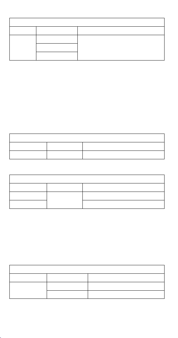
Afche l’état de la pile
L’utilisateur connaît l’état de la pile grâce au témoin de celle-ci
État de la pile Description
La pile est à pleine charge
Il reste 2/3 d’autonomie à la pile
Il reste 1/3 d’autonomie à la pile
Remplacer la pile dès que le témoin de
pile faible apparaît pour éviter les mesures
erronées.
Reportez-vous à la section ENTRETIEN ET RÉPARATION pour le changement
de pile.
20
Page 59

CARACTÉRISTIQUES
Caractéristiques générales
Afchage du compte : 10 000 ou 4 000
Fréquence de mesure : 3 fois par seconde.
Afchage des dépassements de calibre : « OL » ou « -OL ».
Mise en veille automatique : environ 15 minutes.
Témoin de pile faible :
apparaît à l’écran.
Alimentation : pile 9 V.
Durée de vie de pile : ALCALINE 9 V 50 heures (sans rétroéclairage).
est affiché. Remplacez la pile lorsque le témoin
Conditions ambiantes
Utilisation à l’intérieur des locaux
Étalonnage : Cycle d’étalonnage d’un an.
Température de fonctionnement : -0 °C à 10 °C
11 °C à 30 °C (≦ 80 % HR)
30 °C à 40 °C (≦ 75 % HR)
40 °C à 50°C (≦ 45 % HR)
Température d’entreposage : -10 % à 50 °C pour la gamme de courant,
-20 à 60 °C pour d’autres fonctions,
0 à 80 % HR (pile non installée).
Coefcient thermique : 0,2 x (précision spécifiée) / °C, < 18 °C, > 28 °C.
Catégorie de surtension : CAT IV 600 V, CAT III 1000 V
CAT Champ d’application
I Les circuits ne sont pas reliés à l’alimentation secteur
II Les circuits sont directement reliés à l’installation à basse
tension.
III L’installation du bâtiment.
IV La source d’installation à basse tension.
Directives CENELEC : Cet instrument est conforme à la directive CENELEC
2006/95/CE sur les basses tensions, et à la directive 2004/108/CE sur la
compatibilité électromagnétique.
Conformité de sécurité :
- IEC/EN 61010-1 Ed. 3.0, UL 61010-1(2nd Ed.), CAN/CSA-C22.2 No.610101-04 pour mesures de catégorie III 600 V, degré de pollution 2
- IEC/EN 61010-2-030
- IEC/EN 61010-2-032, CAN/CSA-C22.2 No.61010-2-032-04
- IEC/EN 61010-031 (connexions d’essai)
CEM: conforme à toutes les exigences applicables définies par IEC/EN
61326-1
Altitude de fonctionnement : jusqu’à 2 000 m (6 562 pieds)
Taille de conducteur :
37 mm de diamètre pour les modèles ACD-50NAV, ACD-51NAV, ACDC-52NAV
42 mm de diamètre pour les modèles ACD-53NAV, ACDC-54NAV
Résistance aux chocs/vibrations : Vibration sinusoïdale selon MIL-T-28800E
(5 à 55 Hz, 3 g maximum).
Protection contre les chutes : Chute à 1,20 mètres sur sol en béton
ou parquet
21
Page 60

Caractéristiques électriques
La précision est sous la forme ± (% du résultat + nombre de chiffres) à 23 °C
± 5 °C < 80 % HR.
(1) Tension
ACD-50NAV, ACD-51NAV, ACDC-52NAV, ACD-53NAV, ACDC-54NAV
Fonction Gamme Précision*
DC V
AC V
LPF
* Pour V c.c. (DCV) < 1 000 chiffres, ajouter 6 chiffres à la précision. Pour
V c.a. (ACV) < 1 000 chiffres, ajouter 6 chiffres à la précision.
Protection contre les surcharges : 1 000 V eff.
Impédance d’entrée : 3,5 M // <100 pF
Type de conversion c.a. : Les conversions c.a. sont à liaison en courant
alternatif, à valeur efficace vraie, et étalonnées sur la valeur efficace d’un
signal d’entrée sinusoïdal. Les précisions sont données pour un signal
sinusoïdal à pleine échelle et un signal non sinusoïdal sous la demi-échelle.
Pour une onde non sinusoïdale (50/60 Hz) ajouter les corrections suivantes
au facteur de crête :
Pour un facteur de crête de 1,4 à 2,0, ajouter 1,0 % à la précision.
Pour un facteur de crête de 2,0 à 2,5, ajouter 2,5 % à la précision.
Pour un facteur de crête de 2,5 à 3,0, ajouter 4,0 % à la précision.
CF 3 à 460 V, 460 A (pour ACD-53NAV, ACDC-54NAV),
280 A (pour ACD-50NAV, ACD-51NAV, ACDC-52NAV)
2 à 690 V, 690 A (pour ACD-53NAV, ACDC-54NAV),
420 A (pour ACD-50NAV, ACD-51NAV, ACDC-52NAV)
Précision Veff c.a. + c.c. : identique à la caractéristique V c.a.
caractéristique +V c.c.
99,99 V
999,9 V
99,99 V
999,9 V
99,99 V
999,9 V
± (0,7 % + 2 chiffres)
1,0 % + 4 c (50 Hz à 500 Hz)
50 à 60 Hz ± (1 % + 5 chiffres)
61 à 400 Hz ± (5 % + 5 chiffres)
(2) Courant
ACD-50NAV, ACD-51NAV, ACD-53NAV
Fonction Gamme Précision
99,99 A
AC A
LPF
AC A
* ACD-50NAV, ACD-51NAV : 599,9 A ; ACD-53NAV : 999,9 A
* Pour la valeur mesurée < 1 000 chiffres, ajouter 5 chiffres à la précision.
599,9 A /
999,9 A*
0,10 A à 99,99 A
599,9 A /
999,9 A*
50 à 60 Hz ± (1,5 % + 5 chiffres) **
61 à 400 Hz ± (2 % + 5 chiffres) **
50 à 60 Hz ± (1,5 % + 5 chiffres) **
61 à 400 Hz ± (5 % + 5 chiffres) **
22
Page 61

ACDC-52NAV, ACDC-54NAV
Fonction Gamme Précision
99,99 A ± (1,5 % + 0,2 A)
DC A
AC A
LPF
AC A
* ACDC-52NAV : 599,9 A ; ACDC-54NAV : 999,9 A
* Pour la valeur mesurée < 1 000 chiffres, ajouter 5 chiffres à la précision.
Protection contre les surcharges :1 000 Aeff pour ACD-53NAV, ACDC-54NAV
600 Aeff pour ACD-50NAV, ACD-51NAV, ACDC-52NAV
Erreur de position : ± 1 % du résultat.
Le type de conversion c.a. et la précision supplémentaire sont les mêmes
que pour la tension alternative.
Précision Aeff c.a. + c.c. : Identique à la caractéristique A c.a. + A c.c.
• Pour une précision optimale de la mesure des courants élevés, la
mesure ne doit pas durer plus de 10 minutes (pour ACD-50NAV,
ACD-51NAV, ACD-53NAV)
• A c.c. affecté par la température et le magnétisme résiduel.
Appuyez sur la touche HOLD pendant plus de 2 secondes pour compenser.
(3) Maintien de crête : Crête MAX / Crête MIN
Fonction Gamme Précision
AC V
AC A
599,9 A /
999,9 A*
0,10 A à 99,99 A
599,9 A /
999,9 A*
0,10 A à 99,99 A
599,9 A /
999,9 A*
ACD-50NAV, ACD-51NAV, ACDC-52NAVV
140,0 V
1 400 V
140,0 A
850 A
± (1,5 % + 5 chiffres) **
50 à 60 Hz ± (1,5 % + 5 chiffres) **
61 à 400 Hz ± (2 % + 5 chiffres) **
50 à 60 Hz ± (1,5 % + 5 chiffres) **
61 à 400 Hz ± (5 % + 5 chiffres) **
± (3,0 % + 15 chiffres)
± (3,0 % + 15 chiffres)
ACD-53NAV, ACDC-54NAV
Fonction Gamme Précision
AC V
AC A
Protection contre les surcharges : 1 000 Veff
600 Aeff pour ACD-50NAV, ACD-51NAV, ACDC-52NVA
1 000 Aeff pour ACD-53NAV, ACDC-54NAC
Précision dénie pour :
Signal sinusoïdal, V c.a. > 5 Veff / A c.a.
• Uniquement pour les événements répétitifs.
140,0 V
1 400 V
140,0 A
1 400 A
± (3,0 % + 15 chiffres)
± (3,0 % + 15 chiffres)
≧ 5 Aeff, fréq. 50 à 400 Hz.
23
Page 62

(4) Fréquence
ACD-50NAV, ACD-51NAV, ACDC-52NAV, ACD-53NAV, ACDC-54NAV
Fonction Gamme Précision
20,00 à 99,99 Hz
Fréquence
Protection contre les surcharges : 1 000 Veff
600 Aeff pour ACD-50NAV, ACD-51NAV, ACDC-52NAV
1 000 Aeff pour ACD-53NAV, ACDC-54NAV
Sensibilité :
10 à 100 Veff pour la gamme 100 V c.a.
10 à 100 Aeff pour la gamme 100 A c.a. ( > 400 Hz non spécifié)
100 à 1 000 Veff pour la gamme 1 000V c.a.
100 à 600/1 000 Aeff pour la gamme 600 A/1 000 A c.a. ( > 400 Hz non spécifié)
- La mesure sera de 0,0 pour les signaux inférieurs à 10,0 Hz.
(5) Taux de distorsion harmonique :
ACD-50NAV, ACD-51NAV, ACDC-52NAV, ACD-53NAV, ACDC-54NAV
Fonction Gamme Précision
AC A / AC V
Mesure de distorsion harmonique :
ACD-50NAV, ACD-51NAV, ACDC-52NAV, ACD-53NAV, ACDC-54NAV
Ordre des
harmoniques
H01 à H12
H13 à H25 ± (10 % + 10 chiffres)
Protection contre les surcharges : 1 000 Veff
600 Aeff pour ACD-50NAV, ACD-51NAV, ACDC-52NAV
1 000 Aeff pour ACD-53NAV, ACDC-54NAV
• Si V c.a. < 10 Veff ou A c.a. < 10 Aeff, le message afche « rdy » (prêt).
• Si la fréquence du fondamental est en dehors de la gamme 45 à
20,00 à 999,9 Hz
0,020 à 9,999 kHz
99,9 %
Gamme Précision
99,9 %
65 Hz, l’appareil affiche « out.F ».
± (0,5 % + 3 chiffres)
± (3,0 % + 10 chiffres)
± (5 % + 10 chiffres)
(6) Courant d’appel :
ACD-50NAV, ACD-51NAV, ACDC-52NAV, ACD-53NAV, ACDC-54NAV
Fonction
AC A
* ACD-50NAV, ACD-51NAV, ACDC-52NAV : 599,9 A
ACD-53NAV, ACDC-54NAV : 999,9 A
Gamme Précision
99,99 A ± (2,5 % + 0,2 A)
599,9 A / 999,9 A * ± (2,5 % + 5 chiffres)
24
Page 63

Protection contre les surcharges : 1 000 Veff
600 Aeff pour ACD-50NAV, ACD-51NAV, ACDC-52NAV
1 000 Aeff pour ACD-53NAV, ACDC-54NAV
Précision dénie pour :
Signal sinusoïdal, A c.a.
- Temps d’intégration environ 100 m secondes
(7) Puissance active : Watt (c.c./c.a.)
ACD-50NAV, ACD-51NAV, ACDC-52NAV, ACD-53NAV, ACDC-54NAV
Fonction Gamme Précision
AC W / DC W
* ACD-50NAV, ACD-51NAV, ACDC-52NAV : 599,9 KW
ACD-53NAV, ACDC-54NAV : 999,9 KW
* Pour une mesure < 1 000 kW, ajouter 10 chiffres à la précision.
Protection contre les surcharges : 1 000 Veff
600 Aeff pour ACD-50NAV, ACD-51NAV, ACDC-52NAV
1 000 Aeff pour ACD-53NAV, ACDC-54NAV
Précision dénie pour :
W c.a. :
Signal sinusoïdal, V c.a.
Fréq. 50 à 60 Hz, PF=1,00
W c.c. (ACDC-52NAV, ACDC-54NAV uniquement) :
≧ 10V, A c.a. ≧ 5 A
V c.c.
≧ 10 Aeff, fréq. 50/60 Hz
9,999 KW**
99,99 KW
599,9 KW /
999,9 KW*
≧ 10 Veff, A c.a. ≧ 5 Aeff
A, erreur×V, résultat +
V, erreur×A, résultat
(8) Facteur de puissance :
ACD-50NAV, ACD-51NAV, ACDC-52NAV, ACD-53NAV, ACDC-54NAV
Fonction Gamme Précision*
PF
* Pour A c.a. (ACA) < 100 A, ajouter ± 2° à la précision (pour ACD-50NAV,
ACD-51NAV, ACD-53NAV)
Protection contre les surcharges : 1 000 Veff
600 Aeff pour ACD-50NAV, ACD-51NAV, ACDC-52NAV
1 000 Aeff pour ACD-53NAV, ACDC-54NAV
-1,00 à 0,00 à 1,00
± 3° ± 1 c
25
Page 64

(9) Résistance \ Continuité \ Diode :
ACD-50NAV, ACD-51NAV, ACDC-52NAV, ACD-53NAV, ACDC-54NAV
Fonction
Résistance
Continuité
Diode
Protection contre les surcharges : 1 000 Veff
Courant de test max. : environ 0,5 mA.
Tension maximum en circuit ouvert pour ,
Tension maximum en circuit ouvert pour une diode : environ ± 1,8 V
Contrôle de continuité :
Seuil de continuité : < 30 ohms, bip actif.
< 100 ohms, bip inactif.
Indicateur de continuité : Avertisseur avec tonalité de 2 KHz
(10) Capacité :
ACD-50NAV, ACD-51NAV, ACDC-52NAV, ACD-53NAV, ACDC-54NAV
Fonction Gamme Précision
Capacité
Protection contre les surcharges : 1 000 V eff.
Gamme
999,9
9,999 k
99,99 k
999,9
0,40 à 0,80 V
3,999 μF
39,99 μF
399,9 μF
3 999 μF
Précision
± (1,0 % + 5 chiffres)
± (1,0 % + 5 chiffres)
± (1,0 % + 5 chiffres)
± 0,1 V
environ 3 V
± (1,9 % + 8 chiffres)
(11) Température :
ACD-51NAV, ACDC-54NAV
Fonction Gamme Précision
-50 °C à 99,9 °C ± (1 % + 2 °C)
°C
°F
Protection contre les surcharges : 1 000 Veff
• La caractéristique ci-dessus suppose une stabilité de température
ambiante de ± 1 °C. La sonde de température doit être en outre
reliée à la pince multimètre pendant plus d’une heure avant la
mesure.
• Laisser la pince multimètre se stabiliser pendant 2 heures pour une
variation de température ambiante supérieure à ± 5 °C.
100 °C à 399,9 °C
400 °C à 1 000 °C
-58 °F à 211,9 °F ± (1 % + 4 °F)
212,0 °F à 751,9 °F
752 °F à 1 832 °F
± (1 % + 1 °C)
± (1 % + 2 °F)
26
Page 65

(12) μA c.c. :
ACDC-51NAV
Fonction Gamme Précision
DC μA 999,9 μADC ± (1,7 % + 2 chiffres)*
* Pour < 1 000 chiffres, ajouter 6 chiffres à la précision.
Protection contre les surcharges : 1 000 Veff
ENTRETIEN ET RÉPARATION
ATTENTION
Pour éviter les chocs électriques, débrancher le multimètre des circuits,
enlever les cordons de mesure des prises d’entrée et régler la pince sur OFF
avant d’ouvrir le boîtier. Ne pas utiliser l’appareil si le boîtier est ouvert.
Installer uniquement le même type de pile ou équivalent
Dépannage
Si l’appareil ne fonctionne pas correctement, vérifiez la pile, les cordons,
etc. et remplacez-les au besoin. Vérifiez la procédure de fonctionnement
décrite au début de ce mode d’emploi. Si la borne d’entrée tensionrésistance de l’appareil est soumise à une tension transitoire élevée
(provoquée par la foudre ou par une surtension par commutation sur le
réseau) par accident ou d’autres conditions anormales de fonctionnement,
les résistances des fusibles série sautent (adoptent une impédance élevée,
coupure) à la façon des fusibles pour protéger l’utilisateur et l’appareil. La
plupart des fonctions de mesures empruntant cette borne sont ensuite dans
un circuit ouvert. Le remplacement des résistances de fusibles série et des
spintermètres doit être confié à un technicien qualifié. Consultez la section
GARANTIE LIMITÉE pour obtenir des renseignements sur la garantie et le
service après-vente.
Nettoyage et entreposage
Nettoyez régulièrement le boîtier avec un chiffon humide et du détergent
doux. N’utilisez ni abrasifs ni solvants. Si la pince multimètre doit rester
inutilisée pendant plus de 60 jours, retirez la pile et rangez-la séparément.
Changement des piles
1. Éteignez la pince et retirez les cordons de mesure.
2. Desserrez la vis de la trappe d’accès à la pile sur le boîtier. Soulevez la
trappe d’accès pour accéder au compartiment.
3. Remplacez la pile (pile alcaline de 9 V NEDA1604A, JIS6AM6 ou
CEI6LF22).
4. Remettez la trappe d’accès à la pile et revissez-la.
27
Page 66

ATTENTION
Retirer les cordons de mesure de la pince avant d’ouvrir le couvercle de la
pile ou le boîtier de l’appareil.
28
Page 67

ACD-50NAV
600 A AC
Navigator-Zangenmessgerät
ACD-51NAV
600 A AC TRMS
Navigator-Zangenmessgerät
ACDC-52NAV
600 A AC/DC TRMS
Navigator-Zangenmessgerät
ACD-53NAV
1000 A AC TRMS
Navigator-Zangenmessgerät
ACDC-54NAV
1000 A AC/DC TRMS
Navigator-Zangenmessgerät
Bedienungshandbuch
7/2013, Rev. 2
©2013 Amprobe Test Tools.
Alle Rechte vorbehalten. Gedruckt in Taiwan.
Deutsch
Page 68

Beschränkte Gewährleistung und Haftungsbeschränkung
Es wird gewährleistet, dass dieses Amprobe-Produkt für die Dauer von einem Jahr ab
dem Kaufdatum frei von Material- und Fertigungsdefekten ist. Diese Gewährleistung
erstreckt sich nicht auf Sicherungen, Einwegbatterien oder Schäden durch Unfälle,
Nachlässigkeit, Missbrauch, Änderungen oder abnormale Betriebsbedingungen
bzw. unsachgemäße Handhabung. Die Verkaufsstellen sind nicht dazu berechtigt,
diese Gewährleistung im Namen von Amprobe zu erweitern. Um während der
Gewährleistungsperiode Serviceleistungen in Anspruch zu nehmen, das Produkt mit
Kaufnachweis an ein autorisiertes Amprobe Test Tools Service-Center oder an einen
Amprobe-Fachhändler/-Distributor einsenden. Nähere Einzelheiten siehe Abschnitt
„Reparatur“. DIESE GEWÄHRLEISTUNG STELLT DEN EINZIGEN UND ALLEINIGEN
RECHTSANSPRUCH AUF SCHADENERSATZ DAR. ALLE ANDEREN (VERTRAGLICH
GEREGELTEN ODER GESETZLICH VORGESCHRIEBENEN) GEWÄHRLEISTUNGEN,
EINSCHLIESSLICH DER GESETZLICHEN GEWÄHRLEISTUNG DER MARKTFÄHIGKEIT UND
DER EIGNUNG FÜR EINEN BESTIMMTEN ZWECK, WERDEN ABGELEHNT. DER HERSTELLER
ÜBERNIMMT KEINE HAFTUNG FÜR SPEZIELLE, INDIREKTE, NEBEN- ODER FOLGESCHÄDEN
ODER FÜR VERLUSTE, DIE AUF BELIEBIGER URSACHE ODER RECHTSTHEORIE BERUHEN.
Weil einige Staaten oder Länder den Ausschluss oder die Einschränkung einer
implizierten Gewährleistung sowie den Ausschluss von Begleit- oder Folgeschäden nicht
zulassen, ist diese Gewährleistungsbeschränkung möglicherweise für Sie nicht gültig.
Reparatur
Zu allen Geräten, die zur Reparatur oder Kalibrierung im Rahmen der Garantie oder
außerhalb der Garantie eingesendet werden, muss folgendes beigelegt werden:
Name des Kunden, Firmenname, Adresse, Telefonnummer und Kaufbeleg. Zusätzlich
bitte eine kurze Beschreibung des Problems oder der gewünschten Wartung sowie
die Messleitungen dem Messgerät beilegen. Die Gebühren für außerhalb des
Garantiezeitraums durchgeführte Reparaturen oder für den Ersatz von Instrumenten
müssen per Scheck, Zahlungsanweisung oder Kreditkarte (Kreditkartennummer
mit Ablaufdatum) beglichen werden oder es muss ein Auftrag auf Rechnung an
Amprobe® Test Tools formuliert werden.
Garantiereparaturen oder -austausch – Alle Länder
Bitte die Garantieerklärung lesen und die Batterie prüfen, bevor Reparaturen
angefordert werden. Während der Garantieperiode können alle defekten Geräte zum
Umtausch gegen dasselbe oder ein ähnliches Produkt an den Amprobe® Test ToolsDistributor gesendet werden. Ein Verzeichnis der zuständigen Distributoren ist im
Abschnitt „Where to Buy“ (Verkaufsstellen) auf der Website www.amprobe.com
zu finden. Darüber hinaus können in den USA und in Kanada Geräte an ein
Amprobe® Test Tools Service-Center (Adresse siehe weiter unten) zur Reparatur oder
zum Umtausch eingesendet werden.
Reparaturen und Austausch außerhalb der Garantie – USA und Kanada
Für Reparaturen außerhalb der Garantie in den USA und in Kanada werden die Geräte
an ein Amprobe® Test Tools Service-Center gesendet. Auskunft über die derzeit
geltenden Reparatur- und Austauschgebühren erhalten Sie von Amprobe® Test Tools
oder der Verkaufsstelle.
In den USA: In Kanada
Amprobe Test Tools Amprobe Test Tools
Everett, WA 98203 Mississauga, ON L4Z 1X9
Tel.: 888-993-5853 Tel.: 905-890-7600
Fax: 425-446-6390 Fax: 905-890-6866
Reparaturen und Austausch außerhalb der Garantie – Europa
Geräte mit abgelaufener Garantie in Europa können durch den zuständigen
Amprobe® Test Tools-Distributor gegen eine Gebühr ersetzt werden. Ein Verzeichnis
der zuständigen Distributoren ist im Abschnitt „Where to Buy“ (Verkaufsstellen) auf der
Website www.amprobe.com zu finden.
Amprobe® Test Tools Europe
In den Engematten 14
79286 Glottertal, Deutschland
Tel.: +49 (0) 7684 8009 - 0
*(Nur Korrespondenz – keine Reparaturen und kein Umtausch unter dieser Anschrift.
Kunden in Europa wenden sich an den zuständigen Distributor.)
Page 69

ACD-50 Serie CAT IV Navigator-Zangenmessgerät
1
2
4
3
5
6
7
Backe
1
Voltsense-Lampe
2
Auslöser
3
Hold-/DC A Zero-Taste
4
Drehschalter
5
Anzeige
6
Navigator-Taste
7
V / / Eingang
8
COM-Eingang
9
8
9
Page 70

INHALT
SYMBOLE ........................................................................................................ 1
AUSPACKEN UND UNTERSUCHEN ................................................................. 2
MERKMALE ..................................................................................................... 2
BEDIENUNG .................................................................................................... 3
Durchführen elementarer Messungen ..................................................... 4
Messen von Spannung ............................................................................... 5
Messen von Strom ...................................................................................... 6
AUTO SENSE-Modus ................................................................................... 7
Peak Hold ................................................................................................... 7
Einschaltstrom ............................................................................................ 8
DC A ZERO .................................................................................................. 9
Messen von Frequenz ................................................................................ 9
MAX/MIN/AVG ............................................................................................ 9
THD-Messung (Oberschwingungsgehalt) ................................................. 10
LPF ............................................................................................................... 11
Messen von Wirkleistung (W) / Leistungsfaktor (PF) ............................... 12
Phasendrehung .......................................................................................... 14
OHM-Messung ............................................................................................ 15
Messen von Kondensatorkapazität .......................................................... 16
Messen von Temperatur °C / °F ................................................................. 17
Messen von μA ........................................................................................... 18
AUTOMATISCHE/MANUELLE Bereichswahl .............................................. 19
HOLD-Taste ................................................................................................. 19
Voltsense ..................................................................................................... 20
Summer ....................................................................................................... 20
Einschaltoption .......................................................................................... 20
Batteriezustand .......................................................................................... 20
TECHNISCHE DATEN ....................................................................................... 21
WARTUNG UND REPARATUR ......................................................................... 27
Fehlerbehebung ......................................................................................... 27
Reinigung und Lagerung ........................................................................... 27
Batterieaustausch ....................................................................................... 27
Page 71

SYMBOLE
Vorsicht! Stromschlaggefahr
Anwendung in der
Umgebung von gefährlichen
stromführenden Leitern
zulässig.
Wechselstrom
(AC - Alternating Current).
Temperaturmessung
Kapazitätsmessung
Kontinuitätspiepser
Dieses Symbol wird angezeigt,
um den Bediener zu warnen,
dass eine möglicherweise
gefährliche Spannung
vorhanden ist. D. h. das
Messgerät erkennt eine
Spannung ≧ 30 V bzw. eine
Überlastspannung (OL) in V.
Übereinstimmung mit den
relevanten australischen
Standards.
Dieses Produkt nicht im unsortierten Kommunalabfall entsorgen.
Ein qualifiziertes Recycling-Unternehmen kontaktieren.
Vorsicht! Siehe Erklärung in
diesem Handbuch.
Gerät ist durch
Schutzisolierung oder
verstärkte Isolierung
geschützt.
Gleichstrom (DC - Direct
Current).
Widerstandsmessung
Diodenmessung
Erde, Masse.
Übereinstimmung mit EU-
Vorschriften.
Batterie
Sicherheitsinformationen
• Falls GEFÄHRLICHE STROMFÜHRENDE Teile in der Installation, an der
Maßnahmen durchzuführen sind, ZUGÄNGLICH sein könnten, muss
Individuelle Schutzausrüstung verwendet werden.
• Dieses Handbuch enthält Informationen und Warnungen, die
befolgt werden müssen, um das Messgerät sicher zu betreiben und
in einwandfreien Betriebszustand zu halten. Wenn das Messgerät in
einer hier nicht beschriebenen Art verwendet wird, wird der durch
das Messgerät gebotene Schutz unter Umständen beeinträchtigt.
• Das Messgerät ist ausschließlich für Gebrauch in Gebäuden konzipiert.
• Der Schutzgrad des Messgerätes gegenüber den Bedienern ist
Schutzisolierung gemäß IEC/EN 61010-1 3rd Ed. Ausgabe, Kategorie
III 1000 Volt Wechselspannung und Gleichspannung und Kategorie IV
600 Volt Wechselspannung und Gleichspannung.
• Die Messleitungen vor dem Wechseln von Messgerätfunktionen mit
dem Drehschalter von den Prüfpunkten trennen.
• Niemals eine Verbindung zu einer Spannungsquelle herstellen, wenn sich
der Funktionsdrehschalter in der Position
• Das Messgerät nicht extremen Temperaturen oder hoher
Feuchtigkeit aussetzen.
• Das Messgerät niemals in die Funktion , , oder μA schalten, um
die Spannung eines Stromversorgungsschaltkreises in einem Gerät zu
messen, das eine Beschädigung des Messgeräts und des zu prüfenden
Geräts verursachen könnte.
, , oder μA befindet.
1
Page 72

Messkategorie:
V: Kategorie III 1000 Volt Wechselspannung und Gleichspannung und
Kategorie IV 600 Volt Wechselspannung und Gleichspannung.
A: Kategorie III 1000 Volt Wechselspannung und Gleichspannung und
Kategorie IV 600 Volt Wechselspannung und Gleichspannung.
Gemäß IEC61010-1 3. Ausgabe Messkategorie
Messkategorie IV (CAT IV) für Messungen, die an der Quelle der
Niederspannungsanlage durchgeführt werden. Zu den Beispielen
gehören Stromzähler an Primär-Überstrom-Schutzgeräten und
Rundsteuerungsgeräten.
Messkategorie III (CAT III) für Messungen, die an der Gebäudeinstallation
durchgeführt werden. Zu den Beispielen gehören Reihensteckdosen,
Trennschalter, Verkabelung, einschließlich Kabeln, Sammelschienen,
Anschlusskästen, Schaltern und Steckdosenverteilern in stationären
Installationen, sowie Ausrüstung für industrielle Verwendung und
bestimmte andere Ausrüstung wie stationäre Motoren mit permanenter
Verbindung zu einer stationären Installation.
WARNUNG
Um das Risiko von Feuer und Stromschlag zu verringern, dieses Produkt
nicht Regen oder Feuchtigkeit aussetzen. Zur Vermeidung von Stromschlag
bei Arbeiten mit Spannungen über 60 V Gleichspannung oder 30 V
Wechselspannung eff. die ordnungsgemäßen Sicherheitsvorkehrungen
beachten. Diese Spannungen stellen eine Stromschlaggefahr für den
Bediener dar. Die Spitzen der Messleitungen bzw. den zu prüfenden
Schaltkreis nicht berühren, während Strom an den Schaltkreis angelegt
ist. Die Finger während Messungen stets hinter dem Griffschutz der
Messleitungen halten. Vor jedem Gebrauch die Messleitungen, Anschlüsse
und Sonden bezüglich beschädigter Isolierung und exponiertem Metall
untersuchen. Falls ein Defekt festgestellt wird, das entsprechende Teil
unverzüglich ersetzen. Ausschließlich die zum Lieferumfang gehörenden
Messleitungen verwenden, bzw. diese durch gleichwertige oder bessere
Messleitungen ersetzen.
AUSPACKEN UND UNTERSUCHEN
Der Verpackungskarton sollte Folgendes enthalten:
1 Stomzangenmessgerät
1 Messleitungen (1 Satz)
1 Temparaturadapter und -sonde (nur ACD-51NAV und ACDC-54NAV)
1 Bedienungshandbuch
1 Tragbehälter
1 9 V Alkalibatterie (eingesetzt)
Wenn einer dieser Artikel beschädigt ist oder fehlt, die gesamte Lieferung
zwecks Ersatz an die Verkaufsstelle zurücksenden.
MERKMALE
• True RMS – Echteffektivwert
• Messungen:
o Spannung bis 1000 V Wechselspannung/Gleichspannung,
Widerstand, Frequenz, THD (Oberschwingungsgehalt) und
einzelne Oberschwingungen 1. bis 25., Leistung, Leistungsfaktor
2
Page 73

o Wechselstrom
- Bis 600 A (ACD-50NAV, ACD-51NAV, ACDC-52NAV)
- Bis 1000 A (ACD-53NAV, ACDC-54NAV)
o Gleichstrom
- Bis 600 A (ACDC-52NAV)
- Bis 1000 A (ACDC-54NAV)
o Kapazität
o Temperaturmessung in °C / °F (nur ACD-51NAV, ACDC-54NAV) -
Temperaturadapter und -sonde enthalten
o Gleichstrom-Mikroampere (nur ACD-51NAV)
• Phasendrehungsanzeige
• Berührungslose Spannungserkennung
• Messung des Einschaltstroms für Motoren
• Tiefpasslter für Frequenzumrichter
• Kontinuitätspiepser
• Min., Max. und Smart Data Hold
• Peak Hold (Spitzenwert festhalten)
• Automatische Taschenlampe bei Zangeneinsatz
• Große 10000-Zählwerte-Anzeige mit aktiver Hintergrundbeleuchtung
und analogem Balkendiagramm
• Automatische Ausschaltung (APO)
• Maximale Backenöffnung 45 mm
• Fallbeständig bis 1,2 m
• Deluxe-Tragbehälter enthalten
• CAT IV 600 V / CAT III 1000 V Sicherheitsstandard
BEDIENUNG
Ein / Aus-Taste
3
Einschalten
Page 74

Automatische Ausschaltung (APO)
Nach 15 Minuten Leerlauf
Das Messgerät kann durch Drehen aus der Position OFF in eine andere
Position wieder eingeschaltet werden.
Deaktivieren der automatischen Ausschaltung (APO): Auf der NavigatorTaste Abwärts verwenden und das Messgerät gleichzeitig aus der Position
OFF in eine andere Position einschalten.
Navigator-Taste
AUFWÄRTS
LINKS
EINGABE
RECHTS
ABWÄRTS
Die Navigator-Taste umfasst die abgebildeten 5 Schaltrichtungen. Einfaches
Berühren/Anklicken der gewünschten Schaltrichtung bewirkt Aktivierung
der entsprechenden Funktion.
Durchführen elementarer Messungen
VORSICHT
Vor und nach gefährlichen Spannungsmessungen die Spannungsfunktion
an einer bekannten Quelle, z. B. Netzspannung, testen, um die
Funktionsfähigkeit des Messgeräts zu prüfen.
Beim Anschließen der Messleitungen an das zu prüfende Gerät zuerst
die gemeinsame Messleitung und dann die stromführende Messleitung
anschließen; beim Entfernen der Messleitungen zuerst die stromführende
Messleitung und dann die gemeinsame Messleitung entfernen.
4
Page 75

Messen von Spannung
V
WARNUNG
Zur Vermeidung von Stromschlag, Gefahr oder Beschädigung des
Messgeräts keine Messungen vornehmen, die 1000 V Gleichspannung
oder Wechselspannung eff. überschreiten können. Nicht mehr als
1000 V Gleichspannung oder Wechselspannung eff. an die
Eingangsanschlüsse anlegen.
Hinweis - Wenn die gemessene Spannung höher ist als 30 V Gleichspannung
oder Wechselspannung eff., zeigt die Anzeige das Symbol
5
an.
Page 76

Messen von Strom
I
CAT IV 600V, CAT
III 1000V in Bezug auf
Erdung der Backen.
Griff-/Handschutz.
Messgerät
ausschließlich hinter
Griff-/Handschutz. halten.
I
OK
I
OK
- Keine Leiter in die Zange einführen, während das Messgerät eingeschaltet ist.
- Das ACD-50NAV, ACD-51NAV und ACD-53NAV verfügen nur über
Wechselstrommessmodus.
- Automatische Taschenlampe bei Zangeneinsatz.
VORSICHT
Keine Strommessungen mit den Zangenbacken vornehmen, wenn die
Temperatursonde am Messgerät angeschlossen ist.
6
I
I
OK
I+(-I)=0
Page 77

AUTO SENSE-Modus:
Anzeigemesswert ist der größere Wert von: Nur-Wechselstrom mit
Effektivwert oder Gleichstromwert.
AC-Modus: Nur-Wechselstrom mit Effektivwert (RMS).
DC-Modus: Gleichstromwert.
AC+DC-Modus: Wechselstrom+Gleichstrom Effektivwert (RMS).
Hinweis:
• Den Anzeiger AC, DC oder AC+DC auswählen und dann die
Navigator-Taste drücken, um den AC/DC/AC+DC-Modus zu aktivieren.
• Den Anzeiger AC, DC oder AC+DC auswählen und dann die
Navigator-Taste mehr als 2 Sekunden gedrückt halten, um in den
AUTO SENSE-Modus zurückzukehren.
PEAK HOLD (nur Wechselstrommodus)
1. Im AC V-Modus den Anzeiger auf der Anzeige auswählen, um
den PEAK HOLD-Modus zu aktivieren. Um den PEAK HOLD-Modus zu
beenden, die Navigator-Taste mehr als 2 Sekunden gedrückt halten.
„EINGABE“
>2 SEK.
2. Im AC A-Modus den Anzeiger auswählen und dann die NavigatorTaste mehr als 2 Sekunden gedrückt halten, um den PEAK HOLDModus zu aktivieren. Um den PEAK HOLD-Modus zu beenden, die
Navigator-Taste mehr als 2 Sekunden gedrückt halten, sodass das
Messgerät zu Anzeige
>2 SEK.
zurückkehrt.
>2 SEK.
„EINGABE“
7
Page 78

Im PEAK HOLD-Modus ist das Messgerät aktiviert, um den positiven
Spitzenwert und den negativen Spitzenwert festzuhalten. Im PEAK MAXModus wird der positive Spitzenwert angezeigt. Im PEAK MIN-Modus wird
der negative Spitzenwert angezeigt.
Einschaltstrom : (nur Wechselstrommodus)
Wenn der zu messende Einschaltstrom mehr als 100 A Wechselstrom
betragen kann, vor Aktivierung des Einschaltstroms den Bereich
600 A/1000 A auswählen.
Im AC A-Modus den Anzeiger auf der Anzeige auswählen, um den
Einschaltstrommodus zu aktivieren. Um den Einschaltstrommodus zu
beenden, die Navigator-Taste erneut drücken.
,
Motor
aus
EINGABE
Ausöse-
punkt
,
Motor
ein
,
Zeit
Laden
Einschaltstrom-Messwert
8
Page 79

DC A ZERO (nur ACDC-52NAV, ACDC-54NAV)
Die Backe vom Leiter entfernen.
Die HOLD-Taste mehr als 2 Sekunden gedrückt halten, um die
Restmagnetisierung zu kompensieren.
HOLD > 2 Sek.
HOLD
- DC A Zero ist nur in den Modi AUTO SENSE, DC und AC+DC verfügbar.
Messen von Frequenz (nur Wechselstrommodus)
Den Anzeiger „Hz“ auswählen und dann die Navigator-Taste drücken, um
den Frequenzmessmodus zu aktivieren/zu beenden.
„Hz“
EINGABE
MAX/MIN/AVG
Den Anzeiger „MAX MIN“ auswählen und dann die Navigator-Taste
drücken, um den MAX/MIN/AVG-Modus zu aktivieren. Um den
MAX/MIN/AVG-Modus zu beenden, die Navigator-Taste mehr als
2 Sekunden gedrückt halten.
Der MAX/MIN/AVG-Modus zeichnet die Min.- und Max.-Eingangswerte
auf. Wenn die Eingänge den aufgezeichneten Min.-Wert unterschreiten
oder den aufgezeichneten Max.-Wert überschreiten, wird ein neuer Wert
aufgezeichnet. Der MAX/MIN/AVG-Modus ermittelt auch den Mittelwert
zwischen dem Max.-Wert und dem Min.-Wert.
9
Page 80

„MAXMIN“
„MAXMIN“
EINGABE
MAXMIN > 2 Sek.
„MAXMIN“
„MAXMIN“
Hinweis:
• Die HOLD-Taste im MAX MIN-Modus drücken, um die Aktualisierung
der Max.- und Min.-Werte durch das Messgerät zu stoppen. Wenn
der HOLD-Modus im MAX MIN-Modus aktiviert ist, muss der HOLDModus vor dem MAX MIN-Modus deaktiviert werden.
THD-Messung (Oberschwingungsgehalt)
(nur Wechselstrommodus)
Den Anzeiger „THD“ auswählen und dann die Navigator-Taste drücken, um
den THD-Modus zu aktivieren. THD-F=Effektivwert von Oberschwingung ÷
Effektivwert von Grundschwingung ×100 %. (Oberschwingungen bis 25.)
„THD“
„EINGABE“
10
Page 81

Messung einer einzelnen Oberschwingung
(nur Wechselstrommodus)
Den Anzeiger auswählen und dann die Navigator-Taste drücken,
um den Einzel-Oberschwingungsmodus zu aktivieren. Um den EinzelOberschwingungsmodus zu beenden, die Navigator-Taste mehr als
2 Sekunden gedrückt halten.
Hn=Effektivwert der einzelnen Oberschwingung ÷ Effektivwert der
Grundschwingung × 100 %.
EINGABE
„AUFWÄRTS“
„ABWÄRTS“
„AUFWÄRTS“
„ABWÄRTS“
“
„
“
„
„RECHTS“
„LINKS“
„RECHTS“
„LINKS“
>2 SEK.
LPF (nur Wechselstrommodus)
Den Anzeiger „LPF“ auswählen und dann die Navigator-Taste drücken,
Hochfrequenzrauschen zu beseitigen.
"LPF"
EINGABE
Hinweis: Peak Hold, Einschaltstrom, THD, HZ, Einzel-Oberschwingung und
LPF sind nur im Wechselstrommodus verfügbar.
11
Page 82

Messen von Wirkleistung (W) / Leistungsfaktor (PF)
1. Leistungsmessung - einphasig
Schritt 1. Den Drehschalter in die Position „W“ schalten.
Schritt 2. Die rote Messleitung an den stromführenden Leiter
anschließen und die schwarze Messleitung an den Nullleiter.
Schritt 3. Den Auslöser drücken, um die Transformatorbacken zu öffnen
und dann einen einzigen Leiter einschließen; sicherstellen, dass die
Backen den Leiter einschließen und ordnungsgemäß geschlossen sind.
Schritt 4. Die Navigator-Taste verwenden, um den W/PF-Modus zu wählen.
Hinweis:
• Das „+“-Symbol auf der Backe muss auf der Stromquellenseite liegen.
• Im AUTO SENSE-Modus wird ACW/DCW angezeigt (je nachdem, ob
das Messgerät Wechselstromfrequenz erkennt).
• Das ACD-50NAV, ACD-51NAV und ACD-53NAV verfügen nur über
Wechselstrommessmodus.
Wirkleistungszeichen:
Kein Zeichen: Gibt an, dass der Strom von der Stromquelle zur Last fließt.
„_“-Zeichen: Gibt an, dass der Strom von der Last zur Stromquelle fließt.
Leistungsfaktorzeichen:
Kein Zeichen: Die Phase des aktuellen Signals eilt dem Spannungssignal
(induktive Last) nach.
„_“-Zeichen: Die Phase des aktuellen Signals eilt dem Spannungssignal
(Kapazitive Last) voraus.
Überlastanzeige:
OL.U: Spannungsüberlast
OL.A: Stromüberlast
OL.UA: Spannungs- und Stromüberlast.
± OL kW: Wirkleistung > 1000 kW bzw. < -1000 kW.
600V
600A
+L
-N
„PF“
„W“
EINGABE
12
Page 83

2. Leistungsmessung - dreiphasig
A. Dreiphasig, 3 Leiter symmetrisch/unsymmetrisch
Schritt 1. Den Drehschalter in die Position „W“ schalten.
Schritt 2. Die Navigator-Taste verwenden, um den W-Modus zu wählen.
Schwarz
W=W1+W2
2
Rot
Rot
Schwarz
3
1
Verzweigung
oder Stern
B. Dreiphasig, 4 Leiter symmetrisch/unsymmetrisch
Schritt 1. Den Drehschalter in die Position „W“ schalten.
Schritt 2. Die Navigator-Taste verwenden, um den „W“-Modus zu wählen.
W=W1+W2+W3
N
1
2
3
Schwarz
Rot
Schwarz
Schwarz
Rot
Rot
13
Page 84

Phasendrehung
Leitung 1
Leitung 2
Leitung 3
Hinweis:
• Die drei Phasen der Stromquelle wie oben abgebildet anschließen.
• Der Test ist nur verfügbar, während die Systemfrequenz stabil ist.
Schritt 1. Den Drehschalter in die Position „W“ schalten.
Schritt 2. Die Navigator-Taste verwenden, um den „
zu wählen.
Schritt 3. Die rote Messleitung und die schwarze Messleitung an
einen Leiter anschließen (z. B. rote Messleitung an Phasenleitung
1 und die schwarze Messleitung an Phasenleitung 3).
Hinweis: Wenn Folgendes auftritt, ist das Messgerät nicht in der
Lage, die Leitungsphase zu bestimmen:
Der Bildschirm zeigt OLU an und blinkt: Spannung > 1000 V
Der Bildschirm zeigt LoU an und blinkt: Spannung > 30 V
Der Bildschirm zeigt outF an und blinkt: Frequenz > 65 Hz bzw. < 45 Hz
Schritt 4. Wenn der SUMMER zweimal piepst, innerhalb von
3 Sekunden eine der Messleitungen an einen anderen Leiter
anschließen.
Der Bildschirm zeigt das Ergebnis wie folgt an:
“-Modus
a) „1 2 3“ zeigt eine Phasenfolge in Drehrichtung an.
b) „3 2 1“ zeigt eine umgekehrte Phasenfolge an.
14
Page 85

c) „- - - - “ bedeutet, dass die Leitungsphasen nicht bestimmt
werden können.
d) Falls LoU angezeigt wird, wurden die Messleitungen
möglicherweise vor Abschluss der Messgerät-Testverfahren entfernt.
Schritt 5. Um den Test zu wiederholen, die Navigator-Taste
verwenden und den „
“-Modus erneut auswählen.
OHM-Messung
Rot
Schwarz
Rot
Rot
Schwarz
Schwarz
VORSICHT
Zur Vermeidung von Schaden am Messgerät oder an den zu prüfenden
Geräten vor dem Messen von Widerstand oder Dioden den Strom des
Stromkreises abschalten und alle Hochspannungskondensatoren entladen.
Hinweis:
• Den Anzeiger
drücken, um den
• Den Anzeiger
/ / auswählen und dann die Navigator-Taste
/ / -Modus zu aktivieren.
/ / auswählen und dann die Navigator-Taste
mehr als 2 Sekunden gedrückt halten, um in den AUTO SENSE-Modus
zurückzukehren.
Hinweis: Diodenmodus: Wenn der Bildschirm beim Messen einer
Diode „bad“ anzeigt, ist die Diode möglicherweise defekt.
15
Page 86

Messen von Kondensatorkapazität
Den Drehschalter in die Position schalten.
Kapazität
VORSICHT
Zur Vermeidung von Schaden am Messgerät oder an den zu prüfenden
Geräten vor dem Messen von Kapazität den Strom des Stromkreises
abschalten und alle Hochspannungskondensatoren entladen. Die
Gleichspannungsfunktion verwenden, um zu bestätigen, dass der
Kondensator entladen ist.
Hinweis: Das Messgerät zeigt „diSC“ an, während der Kondensator
entladen wird.
16
Page 87

Messen von Temperatur °C/°F
(nur ACD-51NAV und ACDC-54NAV)
Den Drehschalter in die Position schalten.
EINGABE
°F
Entlüf-
Sensor-Typ K
tung
oder
Rohr
Keine Hochspannungsmessungen vor °C/°F-Messungen durchführen, die
Genauigkeit erfordern.
17
Page 88

Messen von μA (nur ACD-51NAV)
Den Drehschalter in die Position μA schalten.
Trennen
18
Page 89

Weitere Funktionen:
AUTOMATISCHE/MANUELLE Bereichswahl
Den Anzeiger RANGE auswählen und dann die Navigator-Taste drücken,
um den Modus „Manuelle Bereichswahl“ zu aktivieren. Um in den Modus
„Automatische Bereichswahl“ zurückzukehren, die Navigator-Taste mehr
als 2 Sekunden gedrückt halten.
Automatische Bereichswahl Manuelle Bereichswahl
Bereich
EINGABE
Bereich
Bereich
>2 SEK.
HOLD-Taste
Die HOLD-Taste drücken, um den Anzeigewert „festzustellen“.
HOLD-Taste-
drücken
SMART HOLD: Das Messgerät piepst kontinuierlich und die Anzeige
blinkt, wenn das gemessene Signal größer ist als der Anzeigewert
(für V.A.W-Funktion).
19
Page 90

Voltsense
Die rote rautenförmige LED leuchtet, wenn die Backen ein elektrisches Feld
erkannt haben.
Summer
Das Messgerät piepst einmal für jeden gültigen Tastendruck und zweimal
für jeden ungültigen Tastendruck.
Einschaltoptionen
Eine der folgenden Tasten drücken und das Messgerät gleichzeitig aus der
Position OFF in eine andere Position einschalten.
Aufwärts auf Navigator-Taste: Zeigt die Softwareversion an.
Abwärts auf Navigator-Taste: Automatische Ausschaltfunktion deaktivieren.
Links auf Navigator-Taste: Aktive Hintergrundbeleuchtung deaktivieren.
HOLD-Taste: Zeigt alle LCD-Symbole ungefähr 10 Sekunden lang an.
Batteriezustand
Der Batteriezustand von der Batterieanzeige angezeigt.
Batteriezustand Beschreibung
Die Batterie ist vollständig ausgeladen.
Die Batterieenergie beträgt 2/3.
Die Batterieenergie beträgt 1/3.
Zur Vermeidung ungenauer Messwerte die
Batterien ersetzen, sobald die Anzeige für
schwache Batterie eingeblendet wird.
Für Informationen über Batterieaustausch im Abschnitt WARTUNG UND
REPARATUR nachschlagen.
20
Page 91

TECHNISCHE DATEN
Allgemeine Spezikationen
Anzeigezählwert: 10000 oder 4000
Messrate: 3 mal pro Sekunde
Überlastanzeige: „OL“ oder „-OL“.
Automatische Ausschaltung: ca. 15 Minuten.
Anzeiger für schwache Batterie:
wenn der Anzeiger auf der Anzeige erscheint.
Stromanforderungen: 9-V-Batterie.
Batterielebensdauer: 9-V-ALKALIBATTERIE, 50 Stunden
(ohne Hintergrundbeleuchtung).
wird angezeigt. Die Batterie ersetzen,
Umgebungsbedingungen
Gebrauch in Gebäuden
Kalibrierung: Kalibrierzyklus: 1 Jahr.
Betriebstemperatur: 0 °C ~ 10 °C
11 °C ~ 30 °C (≦ 80 % RH)
30 °C ~ 40 °C (≦ 75 % RH)
40 °C ~ 50 °C (≦ 45 % RH)
Lagertemperatur: -10 bis 50 °C für Strom
-20 bis 60 °C für andere Funktionen
0 bis 80 % RH (ohne Batterien)
Temperaturkoefzient: 0,2 x (spezifizierte Genauigkeit) / °C, < 18 °C, > 28 °C.
Überspannungskategorie: CAT IV 600 V, CAT III 1000 V
CAT Anwendungsfeld
I Schaltkreise nicht mit Netz verbinden.
II Schaltkreise direkt mit Niederspannungsinstallation
verbunden.
III Gebäudeinstallation.
IV Quelle der Niederspannungsinstallation.
CENELEC-Richtlinien: Das Instrument stimmt mit der CENELECNiederspannungsrichtlinie 2006/95/EG und der Richtlinie zur
elektromagnetischen Verträglichkeit 2004/108/EG überein.
Sicherheitskonformität:
- IEC/EN 61010-1 Ausg. 3.0, UL 61010-1 (2te Ausg.), CAN/CSA-C22.2 Nr.
61010-1-04 bis Messkategorie III 600 V, Verschmutzungsgrad 2
- IEC/EN 61010-2-030
- IEC/EN 61010-2-032, CAN/CSA-C22.2 Nr. 61010-2-032-04
- IEC/EN 61010-031 (Messleitungen)
EMV: Erfüllt alle zutreffenden Anforderungen in IEC/EN 61326-1
Betriebshöhenlage: bis 2000 m
Leiterdurchmesser:
37 mm für ACD-50NAV, ACD-51NAV, ACDC-52NAV
42 mm für ACD-53NAV, ACDC-54NAV
Stoß- und Vibrationsfestigkeit: Sinusschwingung gemäß MIL-T-28800F
(5 ~ 55 Hz, 3 g max.)
Fallschutz: 1,2 m Fall auf Hartholz- oder Betonboden
21
Page 92

Elektrische Spezikationen
Genauigkeit ist ± (% Messwert + Anzahl Stellen) bei 23 °C ± 5 °C < 80 % RH.
(1) Spannung
ACD-50NAV, ACD-51NAV, ACDC-52NAV, ACD-53NAV, ACDC-54NAV
Funktion Bereich Genauigkeit*
DC V
AC V
LPF
* DCV < 1000, 6 Stellen zur Genauigkeit hinzufügen. ACV < 1000, 3 Stellen
zur Genauigkeit hinzufügen.
Überlastschutz: 1000 V eff.
Eingangsimpedanz: 3,5 M // < 100 pF
Wechselstrom-Umwandlungstyp: Wechselstromumwandlungen sind
wechselstromgekoppelt, sprechen auf den Echt-Effektivwert an und
sind auf den Effektivwert eines sinusförmigen Eingangs kalibriert.
Genauigkeiten für sinusförmige Schwingung bei Vollausschlag und
nicht-sinusförmige Schwingung unterhalb Halbausschlag.
Für nicht-sinusförmige Schwingung (50/60 Hz) die folgenden
Spitzenfaktorkorrekturen hinzufügen:
Für Spitzenfaktor 1,4 bis 2,0, 1,0 % zur Genauigkeit hinzufügen.
Für Spitzenfaktor 2,0 bis 2,5, 2,5 % zur Genauigkeit hinzufügen.
Für Spitzenfaktor 2,5 bis 3,0, 4,0 % zur Genauigkeit hinzufügen.
CF 3 bei 460 V,460 A (für ACD-53NAV, ACDC-54NAV)
280 A (für ACD-50NAV, ACD-51NAV, ACDC-52NAV)
2 bei 690 V, 690 A (für ACD-53NAV, ACDC-54NAV)
420 A (für ACD-50NAV, ACD-51NAV, ACDC-52NAV)
AC+DC V eff. Genauigkeit: wie ACV-Spez. +DCV-Spez.
99,99 V
999,9 V
99,99 V
999,9 V
99,99 V
999,9 V
± (0,7 % + 2 Stellen)
± (1,0 % + 5 Stellen)
50 ~ 500 Hz
50 ~ 60 Hz ± (1 % + 5 Stellen)
61 ~ 400 Hz ± (5 % + 5 Stellen)
(2) Strom
ACD-50NAV, ACD-51NAV, ACD-53NAV
Funktion Bereich Genauigkeit
AC A
LPF
AC A
* ACD-50NAV, ACD-51NAV: 599,9 A; ACD-53NAV: 999,9 A
** Gemessener Wert < 1000, 5 Stellen zur Genauigkeit hinzufügen.
99,99 A
599,9 A / 999,9 A*
0,10 A ~ 99,99 A
599,9 A / 999,9 A*
50 ~ 60 Hz ± (1,5 % + 5 Stellen) **
61 ~ 400 Hz ± (2 % + 5 Stellen) **
50 ~ 60 Hz ± (1,5 % + 5 Stellen) **
61 ~ 400 Hz ± (5 % + 5 Stellen) **
22
Page 93

ACDC-52NAV, ACDC-54NAV
Funktion Bereich Genauigkeit
DC A
AC A
LPF
AC A
* ACDC-52NAV: 599,9 A; ACDC-54NAV: 999,9 A
** Gemessener Wert < 1000, 5 Stellen zur Genauigkeit hinzufügen.
Überlastschutz: 1000 A eff. Für ACD-53NAV, ACDC-54NAV
600 A eff. Für ACD-50NAV, ACD-51NAV, ACDC-52NAV
Positionsfehler: ± 1 % von Messwert.
Wechselstrom-Umwandlungstyp und zusätzliche Genauigkeit ist gleich
wie Wechselspannung.
AC+DC A eff. Genauigkeit: Gleich wie ACA-Spez. + DCA-Spez.
• Für bessere Messgenauigkeit von Hochspannung nicht länger als
10 Minuten messen (für ACD-50NAV, ACD-51NAV, ACD-53NAV).
• DC A wird durch Temperatur und Restmagnetisierung beeinusst.
Die HOLD-Taste mehr als 2 Sekunden gedrückt halten, um zu kompensieren.
(3) Peak Hold Peak max. / Peak min. (Spitzenwert)
Funktion Bereich Genauigkeit
AC V
AC A
99,99 A ± (1,5 % + 0,2 A)
599,9 A / 999,9 A* ± (1,5 % + 5 Stellen) **
0,10 A ~ 99,99 A
599,9 A / 999,9 A*
0,10 A ~ 99,99 A
599,9 A / 999,9 A*
ACD-50NAV, ACD-51NAV, ACDC-52NAVV
140,0 V
1400 V
140,0 A
850 A
50 ~ 60 Hz ± (1,5 % + 5 Stellen) **
61 ~ 400 Hz ± (2 % + 5 Stellen) **
50 ~ 60 Hz ± (1,5 % + 5 Stellen) **
61 ~ 400 Hz ± (5 % + 5 Stellen) **
± (3,0 % + 15 Stellen)
± (3,0 % + 15 Stellen)
ACD-53NAV, ACDC-54NAV
Funktion Bereich Genauigkeit
AC V
AC A
Überlastschutz: 1000 V eff.
600 A eff. für ACD-50NAV, ACD-51NAV, ACDC-52NVA
1000 A eff. für ACD-53NAV, ACDC-54NAC
Genauigkeit deniert für:
Sinusschwingung, ACV > 5 V eff. / ACA
• Nur für repetitive Ereignisse geeignet.
140,0 V
1400 V
140,0 A
1400 A
± (3,0 % + 15 Stellen)
± (3,0 % + 15 Stellen)
≧ 5 A eff., Freq. 50~400 Hz.
23
Page 94

(4) Frequenz
ACD-50NAV, ACD-51NAV, ACDC-52NAV, ACD-53NAV, ACDC-54NAV
Funktion Bereich Genauigkeit
20,00 ~ 99,99 Hz
Frequenz
0,020 ~ 9,999 KHz
Überlastschutz: 1000 V eff.
600 A eff. für ACD-50NAV, ACD-51NAV, ACDC-52NAV
1000 A eff. für ACD-53NAV, ACDC-54NAV
Empndlichkeit:
10 ~ 100 V eff. für AC 100 V Bereich
10 ~ 100 A eff. für AC 100 A Bereich ( > 400 Hz unspezifiziert)
100 ~ 1000 V eff. für AC 1000 V Bereich
100 ~ 600/1000 A eff. für AC 600 A/1000 A Bereich ( > 400 Hz unspezifiziert)
- Messwert ist 0,0 für Signale unterhalb 10,0 Hz.
(5) Oberschwingungsgehalt (THD):
ACD-50NAV, ACD-51NAV, ACDC-52NAV, ACD-53NAV, ACDC-54NAV
Funktion Bereich Genauigkeit
AC A / AC V 99,9 % ± (3,0 % + 10 Stellen)
Messung harmonischer Verzerrung:
ACD-50NAV, ACD-51NAV, ACDC-52NAV, ACD-53NAV, ACDC-54NAV
Ordnungszahl Bereich Genauigkeit
H01 ~ H12
H13 ~ H25 ± (10 % + 10 Stellen)
Überlastschutz: 1000 V eff.
600 A eff. Für ACD-50NAV, ACD-51NAV, ACDC-52NAV
1000 A eff. Für ACD-53NAV, ACDC-54NAV
• Wenn ACV < 10 V eff. oder ACA < 10 A eff., wird „rdy“ angezeigt.
• Wenn die Grundschwingungsfrequenz außerhalb des 45 ~ 65 Hz
Bereichs liegt, wird „out.F“ angezeigt.
99,9 %
± (0,5 % + 3 Stellen)20,0 ~ 999,99 Hz
± (5 % + 10 Stellen)
(6) Einschaltstrom:
ACD-50NAV, ACD-51NAV, ACDC-52NAV, ACD-53NAV, ACDC-54NAV
Funktion Bereich Genauigkeit
AC A
* ACD-50NAV, ACD-51NAV, ACDC-52NAV: 599,9 A ACD-53NAV,
ACDC-54NAV: 999,9 A
99,99 A ± (2,5 % + 0,2 A)
599,9 A / 999,9 A * ± (2,5 % + 5 Stellen)
24
Page 95

Überlastschutz: 1000 V eff.
600 A eff. für ACD-50NAV, ACD-51NAV, ACDC-52NAV
1000 A eff. für ACD-53NAV, ACDC-54NAV
Genauigkeit deniert für:
Sinusschwingung, ACA
- Integrationszeit ca. 100-m-Sekunden
(7) Wirkleistung: Watt (DC/AC)
ACD-50NAV, ACD-51NAV, ACDC-52NAV, ACD-53NAV, ACDC-54NAV
Funktion Bereich Genauigkeit
AC W / DC W
* ACD-50NAV, ACD-51NAV, ACDC-52NAV: 599,9 KW
ACD-53NAV, ACDC-54NAV: 999,9 KW
** Gemessener Wert < 1.000 kW, 10 Stellen zur Genauigkeit hinzufügen.
Überlastschutz: 1000 V eff.
600 A eff. für ACD-50NAV, ACD-51NAV, ACDC-52NAV
1000 A eff. für ACD-53NAV, ACDC-54NAV
Genauigkeit deniert für:
AC W:
Sinusschwingung, ACV
Freq. 50 ~ 60 Hz, PF = 1,00
DCW (nur ACDC-52NAV, ACDC-54NAV):
≧ 10 V, DCA ≧ 5 A
DCV
≧ 10 A eff., Freq. 50/60 Hz
9,999 KW**
99,99 KW
599,9 KW / 999,9 KW*
≧ 10 V eff., ACA ≧ 5 A eff.
A,Fehler×V,Messwert+
V,Fehler×A,Messwert
(8) Leistungsfaktor:
ACD-50NAV, ACD-51NAV, ACDC-52NAV, ACD-53NAV, ACDC-54NAV
Funktion Bereich Genauigkeit*
PF -1,00 ~ 0,00 ~1,00 ± 3°± 1 Stelle
* ACA < 100 A, ± 2° zur Genauigkeit hinzufügen (Für ACD-50NAV,
ACD-51NAV, ACD-53NAV)
Überlastschutz: 1000 V eff.
600 A eff. für ACD-50NAV, ACD-51NAV, ACDC-52NAV
1000 A eff. für ACD-53NAV, ACDC-54NAV
25
Page 96

(9) Widerstand und Kontinuität und Diode:
ACD-50NAV, ACD-51NAV, ACDC-52NAV, ACD-53NAV, ACDC-54NAV
Funktion Bereich Genauigkeit
999,9 ± (1,0 % + 5 Stellen)
Widerstand
Kontinuität 999,9 ± (1,0 % + 5 Stellen)
Diode 0,40 ~ 0,80 V ± 0,1 V
Überlastschutz: 1000 V eff.
Max. Prüfstrom: Ca. 0,5 mA.
Max. Leerlaufspannung für ,
Max. Leerlaufspannung für Diode: Ca. ± 1,8 V
Kontinuitätsprüfung:
Kontinuitätsschwellenwert: < 30 Ohm, Piepser ein.
< 100 Ohm, Piepser aus.
Kontinuitätsanzeiger: 2 KHz-Ton-Summer
(10) Kapazität:
ACD-50NAV, ACD-51NAV, ACDC-52NAV, ACD-53NAV, ACDC-54NAV
Funktion Bereich Genauigkeit
Kapazität
Überlastschutz: 1000 V eff.
9,999 k
99,99 k
3,999 μF
39,99 μF
399,9 μF
3999 μF
± (1,0 % + 3 Stellen)
Ca. 3 V
± (1,9 % + 8 Stellen)
(11) Temperatur:
ACD-51NAV, ACDC-54NAV
Funktion Bereich Genauigkeit
-50 °C ~ 99,9 °C ± (1 % + 2 °C)
°C
°F
Überlastschutz: 1000 V eff.
• Die obige Spezikation ist bei einer Umgebungstemperaturstabilität
von ± 1 °C angenommen. Darüber hinaus muss die Temperatursonde
vor der Durchführung der Messung mindestens eine Stunde lang am
Messgerät angeschlossen sein.
• Das Messgerät erfordert 2 Stunden für Stabilität bei einer
Umgebungstemperaturschwankung von mehr als ± 5 °C.
100 °C ~ 399,9 °C
400 °C ~ 1000 °C
-58 °F ~ 211,9 °F ± (1 % + 4 °F)
212,0 °F ~ 751,9 °F
752 °F ~ 1832 °F
± (1 % + 1 °C)
± (1 % + 2 °F)
26
Page 97

(12) DC μA:
ACD-51NAV
Funktion Bereich Genauigkeit
DCμA 999,9 μADC ± (1,7 % + 2 Stellen)
* < 1000, 3 Stellen zur Genauigkeit hinzufügen.
Überlastschutz: 1000 V eff.
WARTUNG UND REPARATUR
VORSICHT
Zur Vermeidung von Stromschlag vor dem Öffnen des Gehäuses das
Messgerät von jeglichen Schaltkreisen trennen, die Messleitungen von
den Eingangsbuchsen abnehmen und das Messgerät AUSSCHALTEN.
Das Messgerät nicht mit offenem Gehäuse betreiben. Ausschließlich den
gleichen Typ von Batterie (oder gleichwertig) einsetzen.
Fehlerbehebung
Falls das Messgerät nicht betrieben werden kann, Batterien, Messleitungen
usw. prüfen und ggf. ersetzen. Die verwendeten Verfahren gemäß
Beschreibung in diesem Handbuch genau prüfen. Falls die SpannungsWiderstands-Eingangsbuchse des Messgeräts zufällig oder durch
abnormale Betriebsbedingungen hohen Spannungsspitzen (verursacht
durch Blitzschlag oder Schaltüberspannung) ausgesetzt wurde, reagieren
die schmelzbaren Reihenwiderstände (sie werden hochohmig) wie
Sicherungen, um den Bediener und das Messgerät zu schützen.
Die meisten Messungen über diese Buchse sind dann offene
Schaltkreise. Die schmelzbaren Reihenwiderstände und die Funkenstrecken
sollten in diesem Fall durch ausgewiesenes Fachpersonal ersetzt
werden. Für Garantieansprüche oder Reparaturservice siehe Abschnitt
BESCHRÄNKTE GEWÄHRLEISTUNG.
Reinigung und Lagerung
Das Gehäuse von Zeit zu Zeit mit einem feuchten Tuch und mildem
Reinigungsmittel abwischen. Keine Scheuer- oder Lösungsmittel
verwenden. Wenn das Messgerät 60 Tage oder länger nicht verwendet
wird, die Batterie entfernen und getrennt aufbewahren.
Batterieaustausch
1. Die Messleitungen entfernen und das Messgerät ausschalten (OFF).
2. Am Gehäuse die Schraube von der Batteriefachabdeckung
losschrauben. Die Batteriefachabdeckung anheben und dadurch das
Batteriefach herausheben.
3. Die Batterie (9 V Alkalibatterie, NEDA1604A, JIS6AM6 oder IEC6LF22)
austauschen.
4. Die Batteriefachabdeckung wieder anbringen und die Schraube
anziehen.
27
Page 98

VORSICHT
Vor dem Öffnen der Batteriefachabdeckung bzw. des Messgerätgehäuses
die Messleitungen vom Messgerät entfernen.
28
Page 99

ACD-50NAV
Pinza amperometrica AC da 600 A con
tasto multiplo di navigazione
ACD-51NAV
Pinza amperometrica AC a vero valore
efcace da 600 A con tasto multiplo
di navigazione
ACDC-52NAV
Pinza amperometrica AC / DC a vero
valore efcace da 600 A con tasto
multiplo di navigazione
ACD-53NAV
Pinza amperometrica AC a vero valore
efcace da 1000 A con tasto multiplo
di navigazione
ACDC-54NAV
Pinza amperometrica AC / DC a vero valore
efcace da 1000 A con tasto multiplo
di navigazione
Italiano
Manuale d’uso
7/2013, Rev. 2
©2013 Amprobe Test Tools.
Tutti i diritti riservati. Stampato in Taiwan.
Page 100

Garanzia limitata e limitazione di responsabilità
Questo prodotto Amprobe sarà esente da difetti di materiale e fabbricazione per un
anno a decorrere dalla data di acquisto. Sono esclusi da questa garanzia i fusibili, le
pile monouso e i danni causati da incidenti, negligenza, uso improprio, alterazione,
contaminazione o condizioni anomale di funzionamento o manipolazione. I rivenditori
non sono autorizzati a offrire nessun’altra garanzia a nome della Amprobe. Per
richiedere un intervento durante il periodo di garanzia, restituire il prodotto, allegando
la ricevuta di acquisto, a un centro di assistenza autorizzato Amprobe Test Tools
oppure a un rivenditore o distributore Amprobe locale. Per ulteriori informazioni
vedere la sezione Riparazioni. QUESTA GARANZIA È IL SOLO RICORSO A DISPOSIZIONE
DELL’ACQUIRENTE E SOSTITUISCE QUALSIASI ALTRA GARANZIA, ESPRESSA, IMPLICITA
O PREVISTA DALLA LEGGE, COMPRESA, MA NON A TITOLO ESCLUSIVO, QUALSIASI
GARANZIA IMPLICITA DI COMMERCIABILITÀ O DI IDONEITÀ PER SCOPI PARTICOLARI.
IL PRODUTTORE NON SARÀ RESPONSABILE DI DANNI O PERDITE SPECIALI, INDIRETTI
O ACCIDENTALI, DERIVANTI DA QUALSIASI CAUSA O TEORIA. Poiché alcuni stati o
Paesi non permettono l'esclusione o la limitazione di una garanzia implicita o di danni
accidentali o indiretti, questa limitazione di responsabilità potrebbe non riguardare
l’acquirente.
Riparazioni
A tutti gli strumenti di misura restituiti per interventi in garanzia o non coperti dalla
garanzia oppure per la taratura, devono essere allegate le seguenti informazioni: il
proprio nome e quello dell’azienda, indirizzo, numero telefonico e ricevuta di acquisto.
Allegare anche una breve descrizione del problema o dell’intervento richiesto e i cavi
di misura. Gli importi dovuti per sostituzioni o riparazioni non coperte dalla garanzia
vanno versati tramite assegno, vaglia bancario, carta di credito con data di scadenza,
oppure ordine di acquisto all'ordine di Amprobe® Test Tools.
Sostituzioni e riparazioni in garanzia – Tutti i Paesi
Leggere la garanzia e controllare la batteria prima di richiedere una riparazione.
Durante il periodo di garanzia, si può restituire uno strumento difettoso al rivenditore
Amprobe® Test Tools per ricevere un prodotto identico o analogo. Nella sezione
“Where to Buy” del sito www.amprobe.com c'è un elenco dei distributori più vicini.
Negli Stati Uniti e nel Canada gli strumenti da sostituire o riparare in garanzia possono
essere inviati anche a un centro di assistenza Amprobe® Test Tools (l’indirizzo è più
avanti).
Sostituzioni e riparazioni non coperte dalla garanzia – Stati Uniti e Canada
Negli Stati Uniti e nel Canada gli strumenti da sostituire o riparare, non coperti
da garanzia, devono essere inviati a un centro di assistenza Amprobe® Test Tools.
Rivolgersi alla Amprobe® Test Tools o al rivenditore per informazioni sui costi delle
riparazioni e sostituzioni.
Stati Uniti Canada
Amprobe Test Tools Amprobe Test Tools
Everett, WA 98203 Mississauga, ON L4Z 1X9
Tel: 888-993-5853 Tel: 905-890-7600
Fax: 425-446-6390 Fax: 905-890-6866
Sostituzioni e riparazioni non coperte dalla garanzia – Europa
Gli strumenti acquistati in Europa e non coperti dalla garanzia possono essere sostituiti
dal rivenditore Amprobe® Test Tools per un importo nominale. Nella sezione “Where to
Buy” del sito www.amprobe.com c'è un elenco dei distributori più vicini.
Amprobe® Test Tools Europe
In den Engematten 14
79286 Glottertal, Germania
Tel: +49 (0) 7684 8009 - 0
*(Solo per corrispondenza – non rivolgersi a questo indirizzo per riparazioni o
sostituzioni. Si pregano i clienti europei di rivolgersi al proprio rivenditore.)
 Loading...