

Page 1
j
y
p
y
p
p
p
p
j
j
j
p
ging
p
g
g
Limited Warranty
Warnings and Important Notes
Unpacking / Packing
Shipping Container Contents
ector Overview
Pro
Front & Rear Panel La
Remote Installation & O
board Installation & Operation
Ke
Local Control Panel & Indicators
Source Connections
Basic O
eration & Men u Navigati on
Auto-Search and Tem
Menu System
out
eration
Channel
A
1
4
6
7
8
9
11
14
15
16
18
19
Picture Command
Source Command
Wizard Command
Setu
User Setu
Menu Command
Chan / Sel Channel Command
Menu Flow Chart
Pro
Lens Ad
Pro
Ceilin
RS-232C Interface Data
Connectors Pin Assi
Command
ector Installation
ustments, Data Tables
ector Dimensions
Mount Information
nments
20
22
23
24
27
29
30
31
32
37
38
40
43
S
ecifications and Options
Chan
5200 User’s Manual / PN 71165 / Revision A
the Lamp Module
ALICE Hel
Guide 1
46
48
50
Page 2

Limited Warranty
AmPro Corp oration warr an ts this product to be fr ee fr om defects in materi al and wor k m ans hi p un d er normal op er ation, subj ect t o
the limitations provided below.
Warranty Period
Date Of Installation
Original Purc ha ser
Warranty Service
Shipping
Environmental
Damage
Serial Numb er
Defaceme nt
Other
NOTICE-PC/ALICE Configuration
system and the ALICE prog r am, w it h out pr i or au th or i z ati on from the fac t ory. Failur e to c ompl y m ay r esu lt in w arr an t y c anc ell at ion.
!
Should AmPro be required to restore the projector back to its original configuration, AmPro WILL charge for labor and/or travel
(shippi ng to-f rom the f act ory) an d/ or m at erials requ ir ed t o d o so.
For the first t wel ve ( 1 2) months af t er date of inst all ati on, but limi t ed to a ma xi mum of fift een (1 5) m onths from dat e
of shipment from the factory, AmPro Corporation will repair or replace any defective part, exclusive of lamp
warrant y of ni n ety ( 90 ) da ys ag ai ns t f ailure to start an d a m axi m um fifty (50) hours of op eration, wit h out c h arge of
labor or parts . Repl acement par ts will be cover ed by this limited war ran t y for the remain d er of t h e warr an ty period.
This Limi t ed Warranty applies on ly to parts su pp li ed or d esi g n ed by A m Pro Corpor at ion.
To establish the date of installation, The AmPro Certificate of Registration should be completed, signed and
returned to AmPro Corporation, postmarked no later than thirty (30) days from date of installation. If the AmPro
Certific ate of R eg is tration is not returned wit hi n such time, AmP r o C orp oration will use the date that t h e proj ec t or
was shipp ed from th e factory as th e dat e of inst al lation.
This Limited Warranty is limited to the original purchaser (end-user) of this product from either AmPro Corporation
or an AmPro Corporation authorized dealer, distributor or agent.
For service under this Limited Warranty, this product must be presented to AmPro Corporation, an authorized
AmPro Corporation service center or the authorized AmPro Corporation selling dealer.
Prior to shipping this product or any sub-assembly to AmPro Corporation, a Return Authorization Number (RA#)
must be obt ai n ed f r om the AmPro C orporati on C us t om er Service Dep artment. T h e prod uc t mus t b e ship p ed in the
manuf act urer’s orig in al s hipping c ontainer or other AmPro Corp orati on approved p ack ag in g. The purc h as er mus t
prepay all freight and shipping charges of this product to AmPro Corporation. Damage resulting from abuse in
shipment of this product is not covered by this Limited Warranty. AmPro Corporation approved shipping containers
are available from AmPro Corporation for a nominal charge.
This Limi t ed Warranty d oes not c ov er d am ag e or rep air s th at ar e n eces sary due t o floods , winds, f ir es, lig hting,
accidents , corrosi v e atm os p h er e, excessi v e exp os ur e to water (m ois ture) or heat, or an y ot h er c ondi ti ons beyond
the control of AmPro Corporation.
This Limited Warranty is void for this product if the serial number has been changed, removed or defaced.
This Limited Warranty does not cover repairs that are necessary due to:
Incorrect in stallation.
Voltage con dit i ons , bl ow n fuses, open circ u it breakers or an y oth er inadequacy or inter ru pti on of proper l y
grounded electrical service.
Misapplication, abuse, impr op er s ervic i ng , or an y oth er im pr oper operation, incl uding mis-adjustments of any
controls .
Defects in or caused by ass oci ated equipm en t.
Repair and/ or m odification of a sub- assembl y p erf or m ed b y oth er th an AmPro Corp or ation fact or y per sonnel.
Usage not in accordance with product instructions
Failure to perform req uir ed pr e ven tative mai ntenance.
This warranty does not cover any items that are in the following categories:
Software -refer to the Software manufacturer for warranty
External devices ( except as spec ifically noted).
Access ories or parts ad d ed to t h e proj ec t or , aft er th e proj ec t or is shi pp ed f r om AmPro Corp or ati on.
Access ories or parts th at are not inst all ed at the f act ory that are includ ed on the pr oduc t st and ar d pr ice
list and purchased from AmPro Corporation or an authorized AmPro dealer or AmPro Service Center are
covered under this warranty.
The ALICE projector operates with an internal PC. DO NOT make any changes to the operating
Normal Maintenance as out lined in the insta llation and servi c ing instru ctions of this User’s Manual will be the responsibility of the purchaser.
!
AmPro Corporation makes no warranty of any kind, express or implied, in connection with this product except as herein above provided. Implied
warranties of merchantability or fitness for a particular purpose or arising from a course of dealing or usage of trade are specifically excluded.
Should this product prove to be defective in material or workmanship, the purchaser’s sole remedy shall be such repair or replacement as herein
above expressly provided and under no circumstances shall AmPro Corporation be liable for any loss, or damage, direct, incidental or
consequential, including loss, or loss of profits or business opportunities, resulting from dealer or distributor installation or services.
Some stat es do not al l ow the exc lusion of inc i dental or consequen ti al damages, s o the ab ov e li mit at ion may not app ly to you. This Limi t e d
W arrant y giv es you sp ecif ic leg al ri ghts , and y ou m ay also have other righ ts , wh ic h m ay v ary, from st at e t o stat e or c ountry. NO other person
is authori z ed to assume f or Am Pro Corpor at i on any addit i on al obl igations b ey ond thos e pro vi d ed herein.
A
5200 User’s Manual
Page 3
Warnings and Important Notes
First
Note
Before operating this equipment, please read this manual carefully and completely. This
manual will prov ide y ou with the necessary informati on of t he m any functions and features,
and the necessary instruc tions for operati on of t his equi pm ent.
Data presented in this manual has been carefully r ev iewed for accuracy and reliability;
however, no responsibility is assumed for i nac c ur aci es. The information contained in this
manual is subject to c hange without prior notic e.
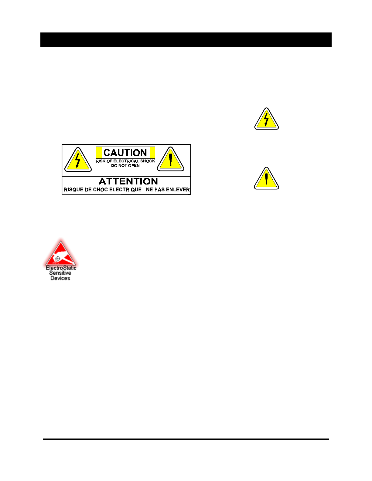
This symbol is intended to alert
the user that parts i nsi de this
product are a risk of electrical
shock to persons.
This symbol is intended to alert
the user that import ant operating
instructions are in the
accompanying literature.
WARNING!
Bright Light
Source
WARNING!
Electrical Shock
WARNING!
UV Radiation
Main AC Line
WARNING! AC
Ground
CAUTION
Electr ostat ic
Sensitive
Devices
This unit has an extremely bri ght light source. Do not look directly into the lens or the beam
of light. Be especial ly c ar eful that children do not stare dir ec tly into the light.
To reduce the risk of electri c al shock, do not expose this product t o r ain or moisture.
The lamp contained i n this product is an intense source of light and heat. One component of
the light emitt ed from this lamp is ultraviolet light.
ASSEMBLY!
ultraviolet radiation. Avoid unnec essary exposure.
Some medicati ons are known to mak e individuals extra sensitive to UV radiation.
The AmPro 5200 Series is auto ranging from 90-240 VAC. There is no need to pr e- c onfigure
any switches.
For your safety and proper operation of the projector, the projector
properly wired and grounded outlet. An impr operl y gr ounded system can place hazardous
voltages on accessible m etal parts of the projector and voids the warranty due to potential
damage to the project or .
This symbol is intended to alert the user that electr ostatic sensitive devic es
are employed in this product. When working inside the equipment, handling
or transporting pri nted circuit boards prot ec t against “Electrostati c
Discharge”.
DO NOT LOOK INTO THE LENS
Potential eye and skin hazards are present when t he lamp is energized due t o
MUST BE
connected to a
1
5200 User’s Manual
Page 4
Warnings and Important Notes
Power Source
Interruptions
Power
Protection
Devices
Warning! Cable
Connections
Ceiling Mount
Precautions
The 5000 Series of projec tor operation is based on a comput er system , not unlik e y our
desktop computer . Sinc e c om puter systems are very sensitive to variations in voltage
supplied by the AC power source. Over-voltage, under- voltage and transients (or spi k es) can
erase data from memory or even c ause components to fail. To protect against these types of
problems, power cables shoul d be pr oper ly grounded and one or both of t he following
methods should be empl oy ed;
Place the system on a dedicated power circuit. Do not all ow the system to share a circuit with
one of the following:
Copier machines Air Conditioners Power Tools
motorized equipm ent
A variety of devices are available that protect against power problems, such as power
surges, transients, and power failures. The following equipment can provide some level of
protecti on;
Surge Protectors Line Conditioners Un-interruptible Power Supply (UPS). A 1.5KWA
UPS minimum recommended.
To avoid damage to the proj ector , power “off” the project or and di sconnect the main AC line
cord before you connect or disconnect the IR receiv er ( s) or any other peri pher al.
In a ceiling mount appli c ation, the strength and rigidity of the ceiling are very important. The
location should be car efully checked befor ehand to determine that the installation will safely
support the weight of t he pr ojec tor.
Teletype machines Any other
NOTE: AmPro Corporation is not respons ible for injury or damage caus ed by an im pr oper ly
installed projector.
Lamp Module
Warnings
Caution
Hot
Lamp Module
Disposal
Lens Cleaning
General Notes
Be sure the lamp and its holder are c ooled before changing lamp or inj ur y to per sonnel
will occur.
The lamp is under great pressure at all times and may explode. To reduce t he ri sk of
personal injur y and/or property damage, when servic ing the projector lamp wear safety
glasses and allow the lam p to cool c om pletely.
Be careful not to touc h the exposed surface of the lamp itself. This could impair lamp
performanc e and shorten l am p life.
The lamp inside the lamp module is under pres sure. Do not incinerat e. Ey e pr otection should
be worn when working with the lam p to avoid injury from metal particl es.
To avoid the risk of scrat c hing the lens, only clean the lens if absolut ely required. A small
amount of dust on the lens will hav e v er y little effect on the pictur e quality. If the lens must be
cleaned, use a dry, soft opti c al quality cloth. Rub very gently in a circular motion.
All safety and operating instructi ons should be read before the projector i s operat ed.
The exterior of the pr ojec tor may be kept in good condition by wipi ng it wit h a cl ean, dry ,
sof t cl oth.
For general safet y, the projector should be cleaned i nternally only by an authoriz ed
AmPro service technic ian.
Do not place magneti c equi pm ent on or near the projector.
Secure service any time the projector is damaged or f ails. An obvious change in
performanc e may also indic ate a need for service.
2
5200 User’s Manual
Page 5

Warnings and Important Notes
General Notes
PC/ALICE
Configuration
Windows® 95
Copy Guarded
Video Material
Do not attempt to servic e the projector yourself by rem ov ing the cov er s.
Doing so may expose you to dangerous voltages or other hazar ds. Refer servicing to
qualified service personnel.
Remove the main power plug fr om the wall socket when the projector has f ailed.
Do not use this projector immediately after mov ing from a low temper ature to high
temperature, as this causes condensation, which m ay r esul t in fi r e, electrical shock, or
other hazards.
When this project or i s used on a cart, car e shoul d be taken to avoid quick stops,
excessive forc e, and uneven surfaces, which may cause the projector and cart to
overturn, damaging the equipment or causing possible injury to operator .
CAUTION: The ALICE projec tor operates with an internal PC. DO NOT make any changes
to the operating system and the ALICE program without prior authorization from the factory.
Failure to comply m ay result in warranty cancellation. Should AmPro be required to restor e
the projector back to its original configuration, AmPro WILL charge for labor and/or travel
(shipping to-from the factory) and/or m aterials required to do so.
Please do not lose the certif icate of Authenticity number th at is attach ed to the front of
the Windows® 95 manual (Product 00000-OEM-000000-00000), because another
number cannot be issued.
We CANNOT provide a replacem ent! This number is keyed to the Windows® 95 CD that you
received with y our ALI CE projector and if lost would make purc hasi ng a new copy a
necessity.
Due to the nature of the encoded proces s used in copy guarded video mat eri al, which is
beyond the control of AmPr o Cor por ation. It is the user’s responsibility to correct f or any
video disturbanc es or artifacts caused by the copy guar ded v ideo m aterial which may affect
the project or ’s operat ion.
Advanced Light Imaging with Computer Enhancement and ALICE are trademarks of AmPro Corporation, Digital Light
Processing , DLP , and the DLP Graphic Device are trademarks of Texas Instruments. Intel Pentiumis a trademark of Intel
Corporation. Microsoft, Windowsare trademarks of Microsoft Corporation.
3
5200 User’s Manual
Page 6
Un-Packing and Packing
Introduction
Description
This section of the manual describes the directions for inspecting the AmPro 5000 Series
standard shipping container, content s and describes steps t o follow when unpacking the
projector shipping cont ainer . Additionally, r eference is provided for r epac k aging the projector
if necessary.
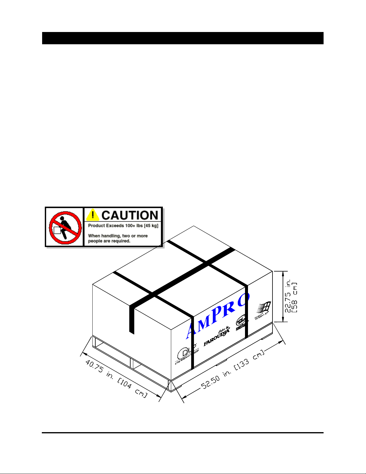
The AmPro 5000 Series is shipped in a cardboard/foam container where it is strapped to a
floating platfor m to protect from shocks and vibrations . A skid on the bottom of the container
allows access for a fork lift. A hollow compartment within the main foam insert contains t he
accessories, ( IR keyboard, remote contr ol, lens and power c or d, et c .). Upon receiving the
5000 Series projector, inspect the shipping cont ainer for any signs of visual damage. After
unpacking, determine that all items ordered are pr es ent. Verify that you received t he pr oper
cables, lens(es) and doc um entation and there is no visual damage to the projector. If any
part is damaged or missing, im m ediately notify the carrier and y ou’r e s elling dealer or c ontact
A
Customer Support personnel.
mPro
4
5200 User’s Manual
Page 7
Un-packing and Packing
Un-Packing
When installing the lens, Do not over tighten or it will becom e diff ic ult to remove.
!
Step 1. Remove the two (2) banding straps from around the shippi ng c ontainer.
Step 2. Remove the top secti on c arton (i tem 1) by sliding it up and over the interi or
sections.
Step 3. Remove the Plywood cover (item 2) and top foam insert (item 3).
Step 4. Remove the Lens (item 5) and accessories (item 4) from the holl ow
compartments
Step 5. Carefully sli de the main foam insert (item 6) up and over the projec tor.
Step 6. Loosen the top locki ng nut on all three level feet. See Det ail A.
Step 7. Remove the four (4) wooden lags bol ts (item 9) securing the t wo shippi ng bar s
(item 8).
Step 8. With the shippi ng bar s remov ed, carefully lift the projec tor off the floating platform
(item 10).
Step 9. Remove one leveling foot at a time and remove the flat washers then, reinstall
the leveling foot.
Step 10. Install t he lens by car efully rotating the lens cl oc k wise (CW ) until it is firmly
attached.
Packing
If the projector is being s hipped for a service related iss ue, chec k with the service provider for what
!
accessories are requir ed to be shipped with the projector .
Step 1. Remove the lens assembly by rotating it counter cl oc k wise (CCW ). Pl ac e the lens
in its’ protective bag.
Step 2. Place the projector on the floating platform (item 10).
Step 3. Slide the two shipping bar s (item 8) in place, making sure a washer is above and
below the bar. Tight en the t op loc k nut down.
Step 4. Slide the main foam i nsert (i tem 6) around the projector. Pl ac e lens and any
accessories into the compartments and the rear of the main insert.
Step 5. Place the top foam cover ( item 3) and plywood cover (item 2) on top of the main
insert.
Step 6. Slide the outside c ar ton over the entire assembly and sec ur e with banding straps.
NOTE: If the projector is to be shipped back to the factory, be sure that the Retur n Author iz ation Number
(RA#) is cleared mark ed on the container.
5
5200 User’s Manual
Page 8
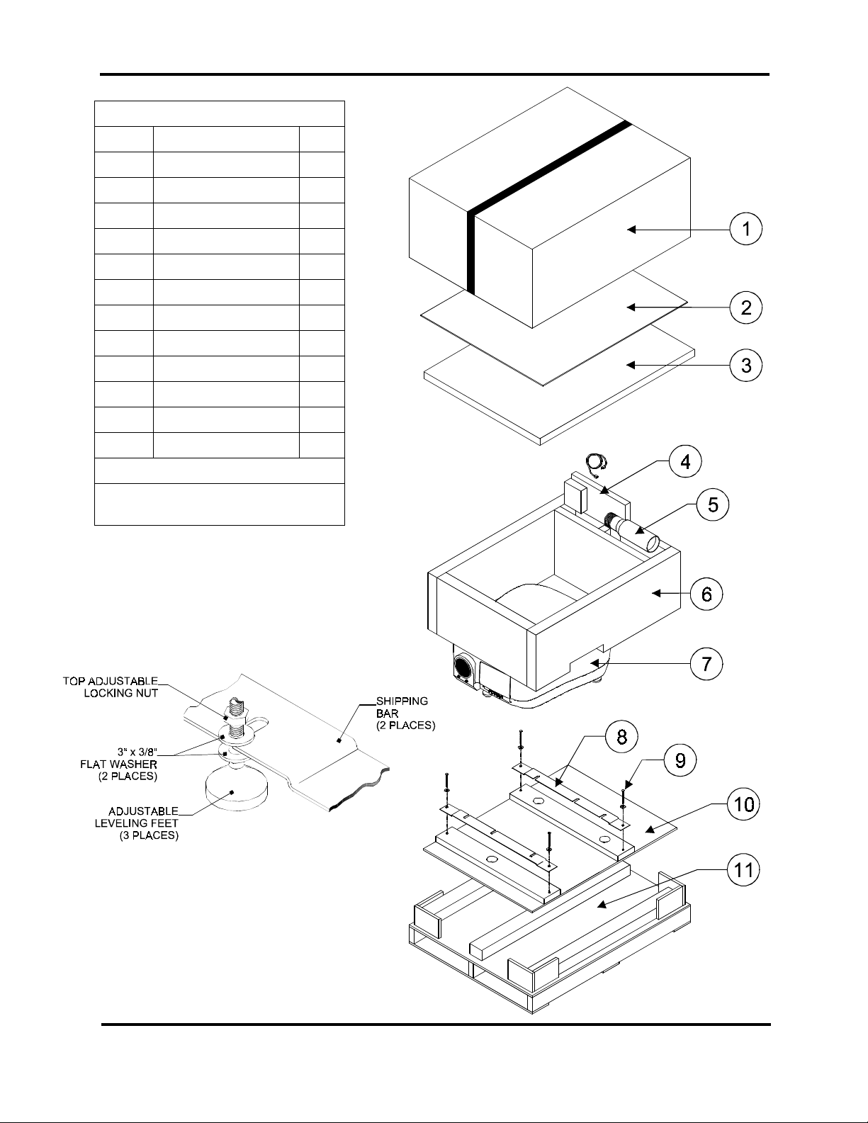
Shipping Cont ainer Contents
Item Description Qty.
1 Shipping Carton 1
2 Plywood Cover 1
3 Foam Cover 1
4 Accessory Boxes 2
5 Lens 1*
6 Foam Insert (Main) 1
7 Projector 1
8 Shipping Mount 2
9 Wood Lag Bolts 4
10 Floating Platf orm 1
11 Skid w/Pallet 1
Ref Optional Items **
*Lens(es) shipped only if ordered
Un-packing and Packing
** Depends on number of options
selected at tim e or order.
Detail A
6
5200 User’s Manual
Page 9
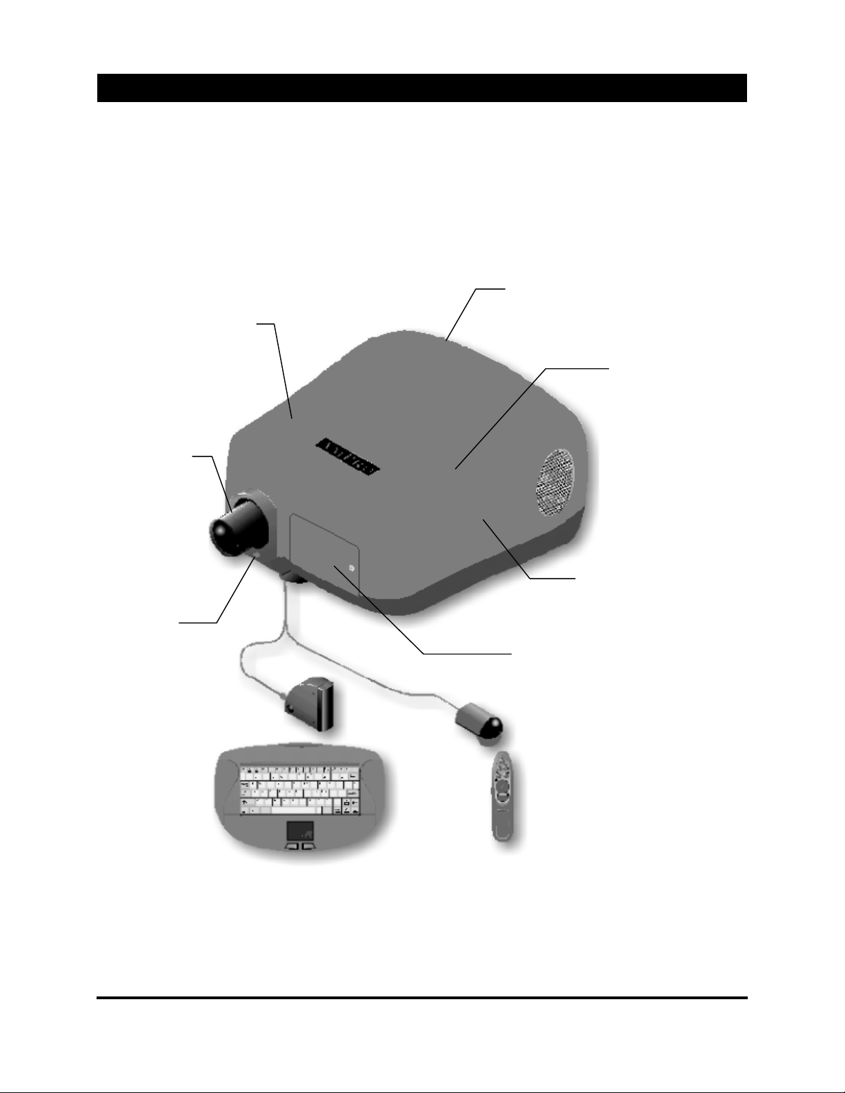
Projector Overview
General
Features
Texas Instruments
3-Chip DLP Engine
Single Lens Design
Choice of 6 lenses
including 2 zoom s
The AmPro 5200 DLP™ projector is the latest in large screen display technology. The
AmPro 5200 is called “ALICE™ - Advanced Light Imaging with Computer Enhancement”
which uses Texas Inst r um ents’ Digital Light Process or thr ee- c hip engine that projects a
bright 1,300 ANSI lumens at a resolution of 848 x 600. With the inherent pr ec is ion of TI’s
DLP™ 10-bit gray scale, A LICE displays true color and sharp det ail in a near pixeliz ation-free
display.
The model 5200 MX includes a Intel P entium 233MMX processor, 4. 2G hard dr iv e, 32M of
memory, 12X (or great er ) CD-ROM, modem, and audio c ontrol card.
Rear Panel
User Changeable Lam p Modul e
Projector Local Cont r ol P ad
Intel 233MMX Processor
4.2G Hard Drive
64M Memory
Windows Operating S y stem
Lens Focus and
Shift Adjusters
Keyboard with
Mouse Pad
Sound Absorbing
Cabinet Design
PC Card Cage Access
CD-ROM & Floppy Drive
Modem & Video Decoder
Infrared
Infrared
Remote Control
and Receiver
7
5200 User’s Manual
Page 10
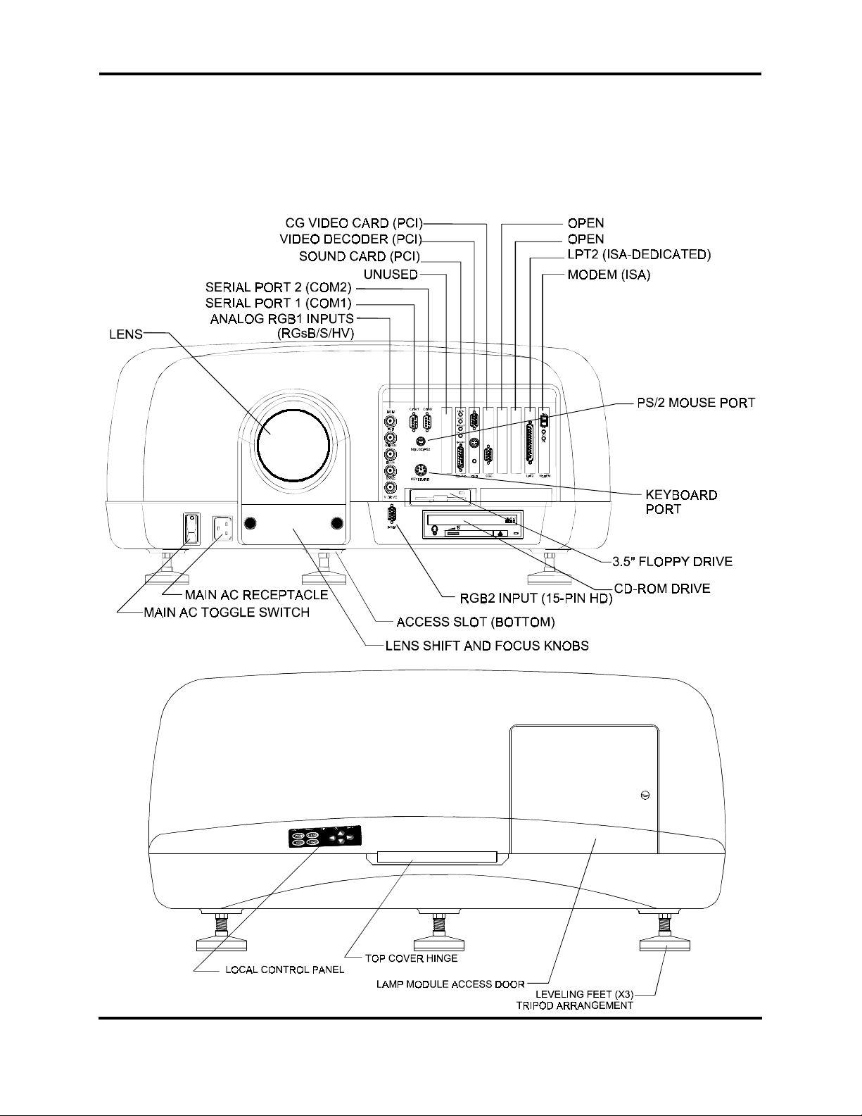
Projector Overvi ew
Front Panel Layout
All external connect ions and the PC Card Cage are located at the f r ont of the pr ojec tor. The main AC
power receptacl e, t he m ain A C toggle/breaker switcher and all the dif ferent video inputs are readily
available.
Open the front access panel t o gain entry to the PC card cage and connectors. T o access the PC card
cage and connectors, tur n the ¼ turn captive screw located on t he left si de of t he access panel , and
gently open the door.
Rear Panel Layout
8
5200 User’s Manual
Page 11
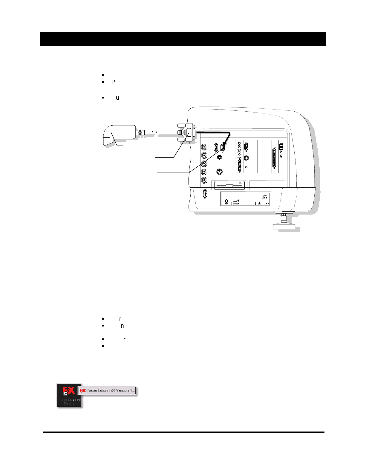
Remote Control Installation and Operation
Connecting the
Receiver
Receiver The ex ternal serial receiver lets you control your mouse from up to 45
feet away. To connect t he Mi nd Path exter nal receiver to your comput er follow
these steps:
Turn off your projector.
Plug the free end of the external serial receiver cable into a serial port 2
(COM2) on your projector .
Turn on your project or.
IR Receiver
Receiver Connect or
Serial Port 2
(COM2)
Posi tioning the
Receiver
Inst a lling the
Battries
Software Notice
Once the receiver i s connected to your projector, t ak e care t o plac e it so the
remote's infr ar ed si gnal c an r eac h it. There ar e two ways to do this. The best way
to position the rec eiv er is so that the infrared signal travels directly from the remote
into the receiver. As you use the remote, aim at the red light on the receiver. If your
presentation room's configuration pr ev ents positioning the rec eiv er this way,
position the r ec eiv er so the i nfrar ed si gnal bounces off a projection screen or wall.
Depending on the distanc es i nv olved and the reflective qualities of the screen or
wall, bounci ng the inf r ar ed si gnal off a screen or wall may perform just as well.
The remote uses 2 AAA alkaline batteries.
To install the batter ies, follow these steps:
Turn the remote upside down wit h its back facing you.
Using your thumb, gently press and slide the battery cover up until the battery
compartment is exposed.
Insert the batt eri es i nto the battery compartment.
Slide the battery cover back into position until it snaps into place.
NOTE: Although you r batteries should last up to 1 year of normal operation, we recommend you
purchase a second set of batteries and carry them with you as a back up. Always use alkaline-type
batteries in your remote.
Your 5200 IR remote Control inc ludes specially configured
operating software.
DO NOT
instructed t o by the factory. Failure to comply will r esul t in
detriment al oper ation of the remote and projector .
remove or edit this software, unless advised and
9
5200 User’s Manual
Page 12
Remote Control Install at io n an d Operat io n
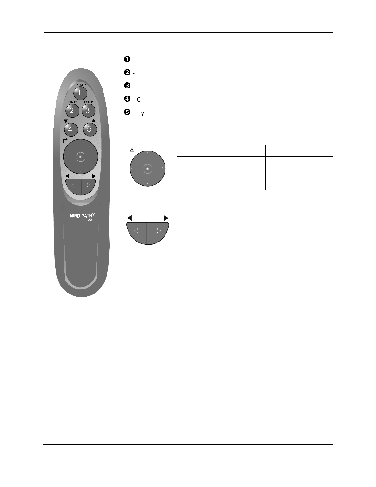
Remote Control
Functions
- Power On, 2nd Function; Toggle between Sources
- Standby; toggle the pr ojec ted image on/off (Video Mute)
- Display Main Menu, Enter highlighted function
- Cycle through control; Use to scroll “left” through cont r ols
- Cycle through controls; Use to scroll “right” through controls.
Mouse Pad
Adjustm e nt Pa d
– Move the mouse cursor, Enter f unction
Press Edge Cursor Moves
Click Center Left Click
Click Center Twice Left Double Click
Press and Hold Center
– Use to increase/decr ease selected function
When a slider control is visible or whenever an
adjustment i s required, use the adjustment pad to
increase or decrease the setting
(1 sec.)
Left Click-and-Dr ag
Until a slider control is visible, the adjustment pad may
be used to scroll left and right through the functi ons.
Within a “List Box”, use the adjustment pad to move between the opti ons.
10
5200 User’s Manual
Page 13
Keyboard Installation and Operation
Inst a lling the
Batteries
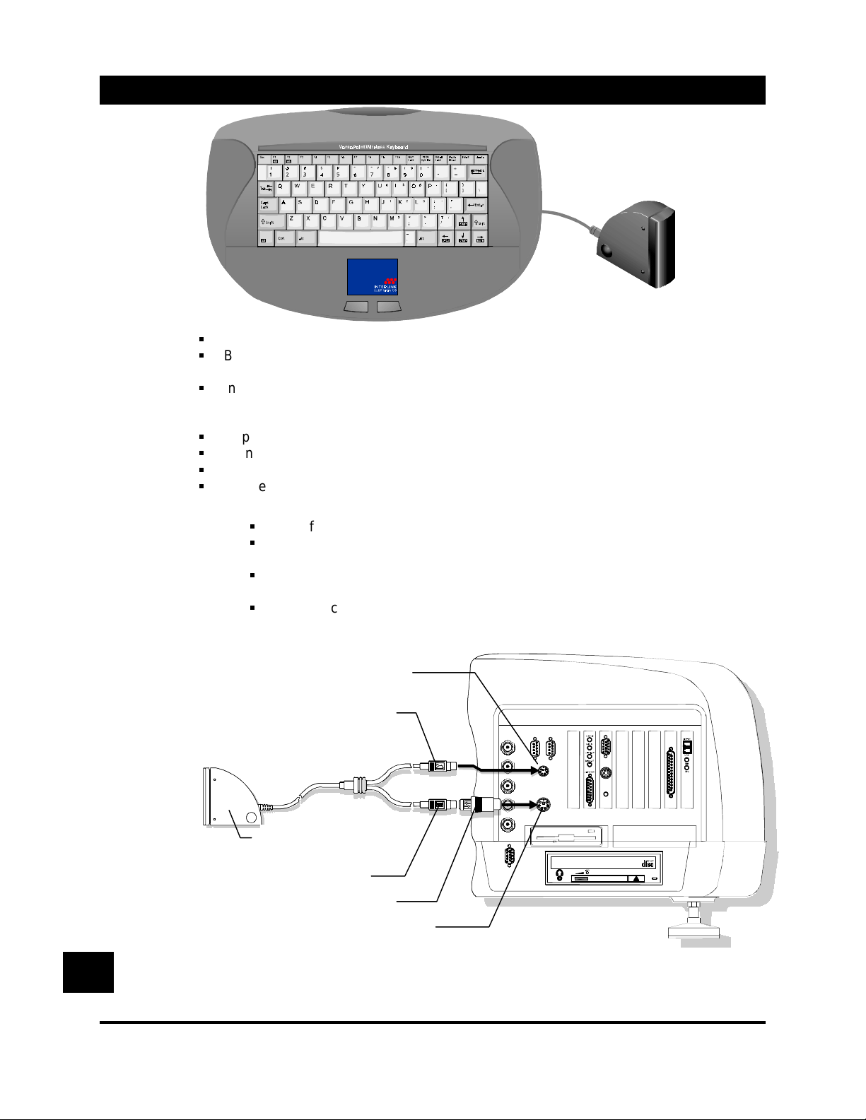
Connecting the
Keyboard
Turn the keyboard ov er onto its face.
By pressing the two latc h tabs simultaneously, pr y open the batt er y door with your
fingers.
Insert 4 AA alkali ne batt eri es with the positive (+) and negative (-) orientation as shown
inside the compartm ent (negative is at the flat end of the bat tery and goes towards the
spring).
Replace the batteries door and make sure both latch tabs snap into place.
Turn the projector off.
Open the front access panel.
Locate the mouse and keyboard ports.
Mouse Connection
Identify the mouse connect or of the “Y” adapter.
Connect the 6-pi n round di n c onnec tor to the mouse port on the projector
Keyboard Connecti on
Identify the keyboar d c onnec tor of the “Y” adapter. The one m arked wit h a
keyboard symbol.
Plug the connector into the port-labeled k ey boar d on your projector.
One all connecti ons are made ( IR Remote and Keyboard), power the proj ec tor on.
PS/2 Mouse Port
Mouse Pad Connector
Keyboard / Mouse Pad
IR Receiver
Keyboard Connector
“AT” Keyboard Adapter
Keyboard Port
The keyboard and mouse cables on the r ec eiver have very similar connections. Take care not to mix
!
them up. No damage will result, but your keyboard and mouse pad will not work proper ly.
11
5200 User’s Manual
Page 14
Keyboard Installation and Operation
Posi tioning the
Receiver
Keyboard
Range
Battery Life
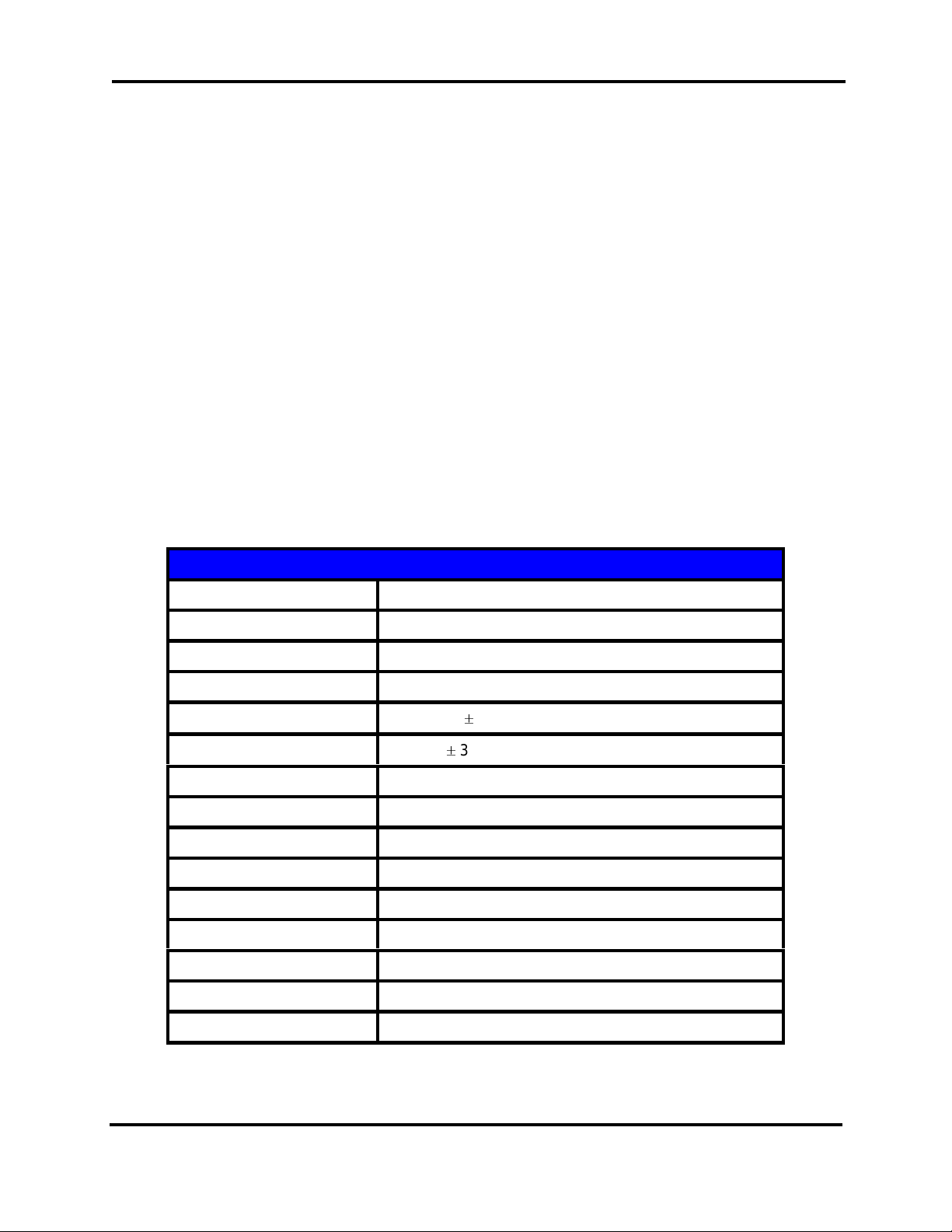
Keyboard Specificat ions
The receiver is multi-positional. It can stand up or lay flat on either side. If you are placing it
on a table or desktop. It is best to stand t he r ec eiver up to minimize any disrupti on of t he
signal by the tabl e or desktop.
When you are mounting or posi tioning the receiver be caref ul not to block the lens from lineof-sight cont ac t wit h the Key boar d. The Keyboard is powerful enough to bounce the infrared
(IR) signal off the walls, but obstructions close to the receiver may interf er e.
Indoors, in the absence of IR light sources, operating ranges will be up to 50 feet (15.2
meters), and, under ideal conditions, beyond. Naturally, indivi dual r esul ts will vary depending
on how you use your keyboard.
Both the keyboard and m ouse pad use what i s known as “sleep mode”. When nothing is
being typed on the keyboard, the IR LED’s and the keyboard proc essor go to “sl eep,”
consuming a mere fraction of their normal power requirements, while waiting f or the next key
press.
Under normal usage, sever al pages per day, battery life of up to a year will be typical. Again,
your results will depend on how you use your k ey boar d.
When it finally com es tim e for batt er y repl ac em ent, y ou will begin to notice a reducti on in
range, typified by lost keys at longer distances. Pl ease use only alkaline batteries only.
Technology Broad Beam Infrared
Number of Keys 79 (equal to 104 when combined wit h the F n Key)
IR Carrier Frequency 36 KHz
Effectiv e Operating Range Up to 50 feet (15 m eters) t y pic al
Effectiv e Operating Angle
Battery Lif e Up to one year (typical)
Power 4 x AA alkaline batteries (6 VDC)
Temperature Operating:5 °F (10 °C) to 132 °F (55 °C)
Keyboard Dimensions 13.8” (35 cm) x 8.5” (22 cm) x 1.6” (4 cm)
Keyboard Weight 1 lb., 9 oz (0.7 kg)
Receiver Dimensions 2.8” (7 cm) x 2.7” (7 cm) x .0.9” (2.3 cm)
Keyboard Connector 6-pin PS/2 mini-DI N
Mouse Connector 6-pin PS/2 mini-DIN
Horizontal: 60° at 5 meters
Vertical: 30° at 5 meters
Storage: -12 °F (-25 °C) t o 158 °F (70 °C)
12
5200 User’s Manual
Page 15
Keyboard Installation and Operation
Keyboard
Operation
Keystrokes Description
The IR remote Control k ey str ok es can be sim ulated using the IR Keyboard. The following is
a list of project or comm ands using t he K ey boar d.
NOTE: The IR Remote Control key equivalent is represented in par enthesis ( )
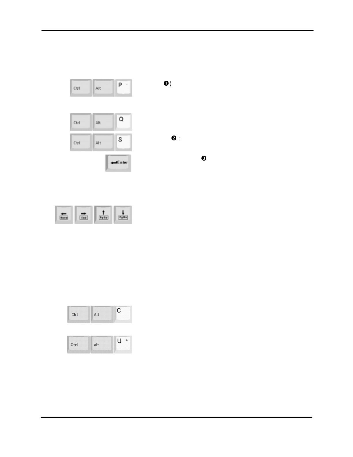
POWER (): Press <Ctrl> <Alt> <P> k e y s simultaneously to power
the display engine “on”.
nd
2
Function: Use <Ctr l> <Alt> <P> to toggle between available
sources.
POWER OFF: Use the <Ctrl> <Alt> <Q> key sequences to explicitly
power-off the displ ay .
STANDBY: (): Press <Ctrl> <Alt> <S> keys simult aneousl y to toggle
the project ed im age On/Off (Video Mute command).
DISPLAY OSD MENU: (): Use the <Enter> key to initially display
the on-screen-display ( M ain Menu)
SELECT: After scrolling through the menu commands, pres s < E nter>
to select the highlighted function f or activation or additional options.
SCROLL: If a command employs an active list window, use the
<Enter> key to scroll t hr ough the options.
SCROLLING: Use the keyboard arrow keys to scroll between options
listed in secondary windows and boxes. When an adjustment meter is
employed, use the arr ow keys to perform the desired adjustm ent.
<Fn> FUNCTION: In addition, use the <Fn> key to enable the
keystroke functi on denoted within the boxed area, i.e., When a window
is present that uses the scroll bars, pressing <Fn>< Hom e> will jump to
the beginning of t he list. Likewise, pressing <Fn><End> will jump to
the end of the list.
ADJUSTMENT: Certain functions use the keyboard arrow keys to
increase and decrease the ac tive function lev els. A gain, the
<Fn><Home>/<E nd> key s work similar as described above.
The following key boar d c ommands are used to select a particul ar channel or source without the use of the onscreen menus.
CHANNEL SELECT: The <Ctrl><Alt><C> command allows the user
to enter the “waiting for channel selection. ” After entering the initial
command, the user enter s< Ctrl><Alt>, then select s a desired c hannel
number between 1 and 9.
SOURCE SELECT: Enteri ng <Ctrl><Alt><U> places the projector into
the “waiting for source c ommand.” After the initi al c om m and. The user
enters <Ctrl>< Al t> , t hen the desir ed source number, see below
<1> = RGB1
<2> = RGB2
<3> = Video
<4> = S-Video
<5> = Int e r n al
13
5200 User’s Manual
Page 16
Local Control and Indicators
Controls
Indicators
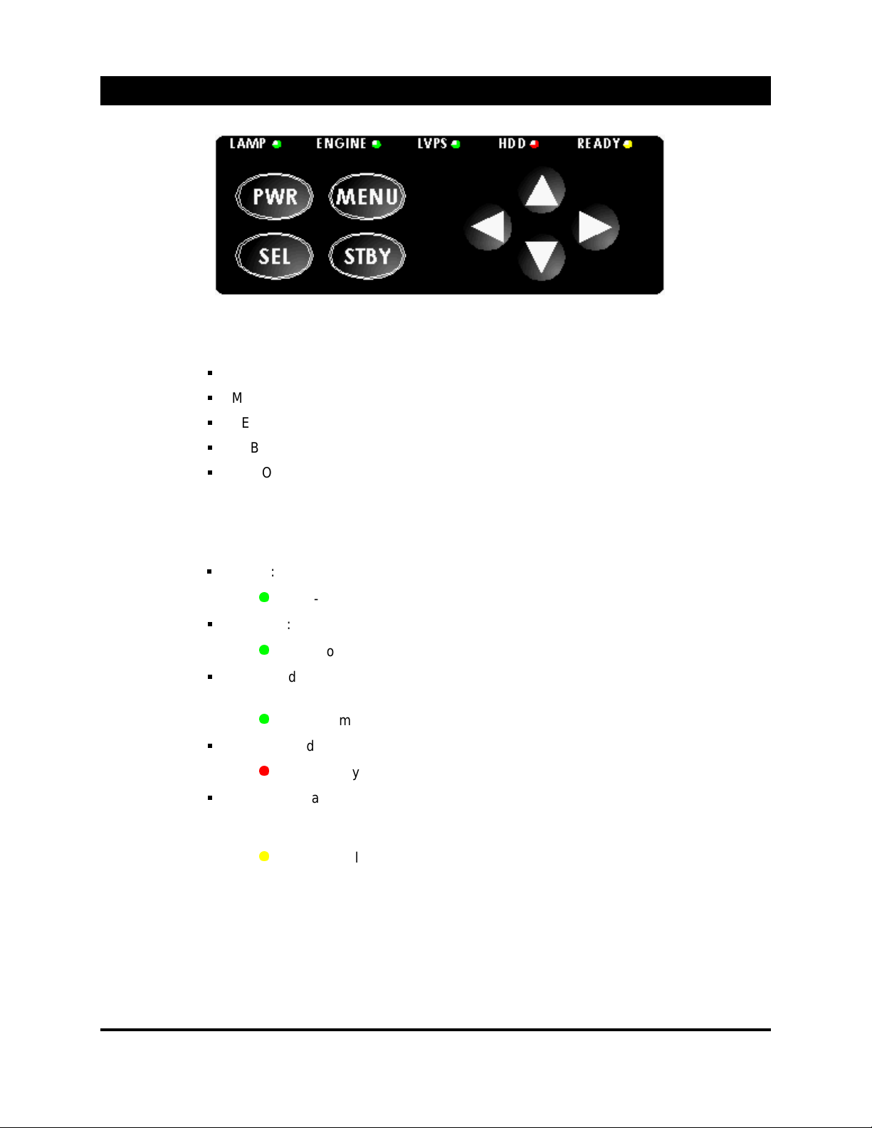
Located at the rear of the projector is the local contr ol panel. The controls allow the user to
perform the foll owing functions.
PWR (POWER): Allows the user to power the projector on and off.
MENU: Enters the On-Screen- Display Mode.
SEL (SELECT): Use the SEL key to select the highlighted function.
STBY (STANDBY): Use to toggle the projected image on or off.
ARROW KEYS: Use to scroll through m enu items. Once an item has been selected, use
the arrow keys to adjust the sel ec ted function.
External L.E.D. Indicators: Located at the rear of t he pr ojec tor (just above the local control
panel) are five L.E.D.s These L.E.D.s will indicate the status of the projector through the boot
sequence and operation.
LAMP: This L.E.D. indicates the lamp power supply is on and the lamp should be lit.
Green-normall y “ON”.
ENGINE: Indicates the display engine is turned “ on” and oper ational.
Green-normall y “ON”.
LVPS: Indicates main AC is applied, switch is “on” and the P.C. power supply i s
operational.
Green-normall y “ON”
HDD: Hard-disk drive. Lights up or flashes when the drive is in use or active.
Red-normall y “F LASHES ”
READY: Initially this indicator blinks, indicating the PC. is in the boot cycle. When the
P.C. has completed t he boot cy cl e, t he L.E.D. will become steady and the projector is
ready for the power-on comm and from the remote control or keyboar d.
Amber- Initially “ B LINKS ”, then “STEADY”.
14
5200 User’s Manual
Page 17
Source Connections
Essential Cabl e
Connections
Refer to the Remote Cont r ol and Keyboard Installation sec tion for information on connecting the IR
!
Remote and Keyboard.
Source
Connection
Before applying AC power t o the 5000 Ser ies pr ojec tor, both IR receivers
CONNECTED
The IR receiver connect ions for the keyboard and remote control are located on the PC
card cage.
To access the PC card cage and connectors, turn the ¼ turn captive screw located on
the left side of the access panel, and gently open the door.
Route the connector s fr om the IR receivers up through the access slot located on the
underside of the projector.
The AmPro 5200 DLP™ projector incorporates “Auto-Search” and “Auto-Setup. This simply
means that the project or will automatically look and s etup t o new s our c es.
“ALICE’s” operation is based on a powerful PC operating s y stem , which inc or por ates an
internal graphics card, so no external source is r equir ed. If no external source is detect ed,
ALICE will automat ic ally s witch to the internal source, pr ov iding that Auto-Search is enabled.
Refer to Basic Operation Section for additional inform ation.
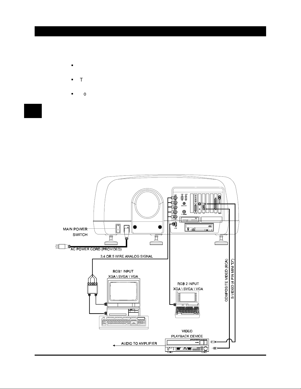
However, if an external sour c e is des ir ed, follow the diagram below for c onnec ting the
source. Remember that A LICE will automatically selec t t he s our c e for you.
.
MUST BE
15
5200 User’s Manual
Page 18
Power Up
Lens Focus /
Shift / Zoom
On-Screen
Menus
Basic Operation and Menu Navigation
The AmPro 5200 Series follows an initial “power-up” sequence from the time the main AC is
toggled “on” to the time an im age is dis play ed.
With the two receiver s i nstalled, plug the main power cord into a receptacle.
Toggle the main ac switch “on” . T he pr ojec tor will automatic ally star t, first displaying the
Windows boot-up screen, then t he S c an Disk operation.
The projector will t hen automatically search f or an exter nal source, if present, the
projector will perform an auto-setup, t hen displ ay the source. If no source is present, the
projector will automatically switch to the internal graphic channel .
NOTE: If more then one external source is present, the project or will switch to the “last
source” selected prior to the last shutdow n.
There are two knobs located dir ec tly below the lens assembly. The knob on the lef t (as
viewed from the front , t able m ounted) is used to perform the lens shift, while the second knob
is used for lens focus. Adjust the Shift/Focus knobs for optimal picture performanc e. If your
projector is equipped with a z oom lens , adjust the image size using the gray r ing ar ound the
lens.
The AmPro 5200 uses a series of overlay menus to control the operation of the projector.
Meaning, whatever sour c e is c ur r ently being dis play ed, the control menu and comm ands ar e
overlaid on top of it. T his tec hnique allows the user to utilize the c ontrols of the projector and
make desired changes while the ac tive source is being used.
To bring-up the main menu, press
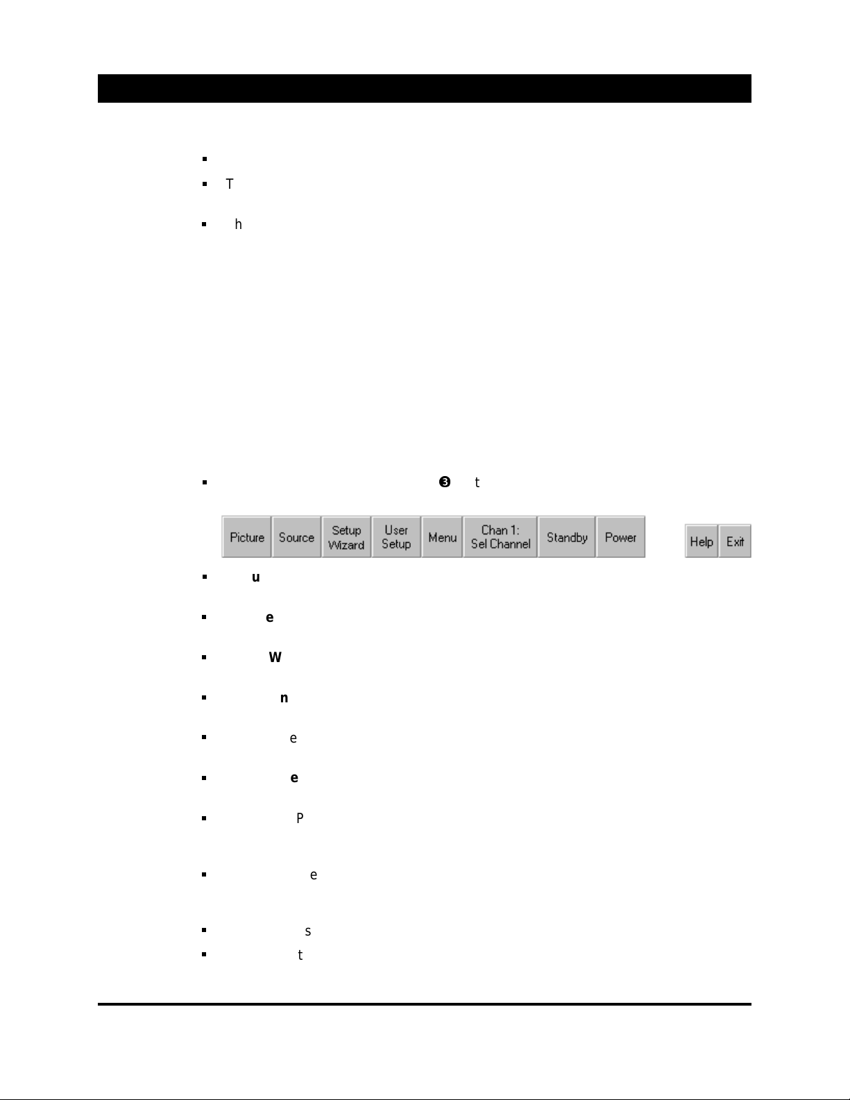
Below illustrates and briefly explains the m ain c ommand set options.
Picture
clock phase and some advance settings as well.
Source
VIDEO etc.
Setup Wizard
sequence. Thi s is useful for the first time user.
User Menu
editing. Ex peri enc e oper ators typically use thi s func tion.
Menu
(channel).
Chan 1: Sel Channel
a channel list dialog box is presented for manual selection of a desired channel setup.
Standby
the center of the Mouse Pad (remote) or <Enter> (keyboard) to redisplay the image.
Also, see Remote Control oper ation.
Power
decision dialog box . In the event this command was entered int entionally, simply selec t
NO on dialog box.
– Allows the user to adjust image quality functions such as, brightness, cont r ast,
– Allows the user to explicitly selec t t he displ ay source type. I.E., RGB, RGB2,
– The Setup Wizard allows the user to step through predetermine setup
– This function allows you to perf orm a random type of channel setup or
– Menu presents additional c ommands and functions for the setup of a source
– This button displays the curr ently active channel. O nc e select ed,
– Puts the projector into the standby mode. Powers the lamp supply off. Press
– Powers the projector (Display engine/Lamp) OFF. Presents the user with a
on the remote control or <E nter> on the keyboard.
Help
– Enters the internal WinHelp help file.
Exit
- Exits the menu system and removes the menu(s) f r om the screen.
16
5200 User’s Manual
Page 19
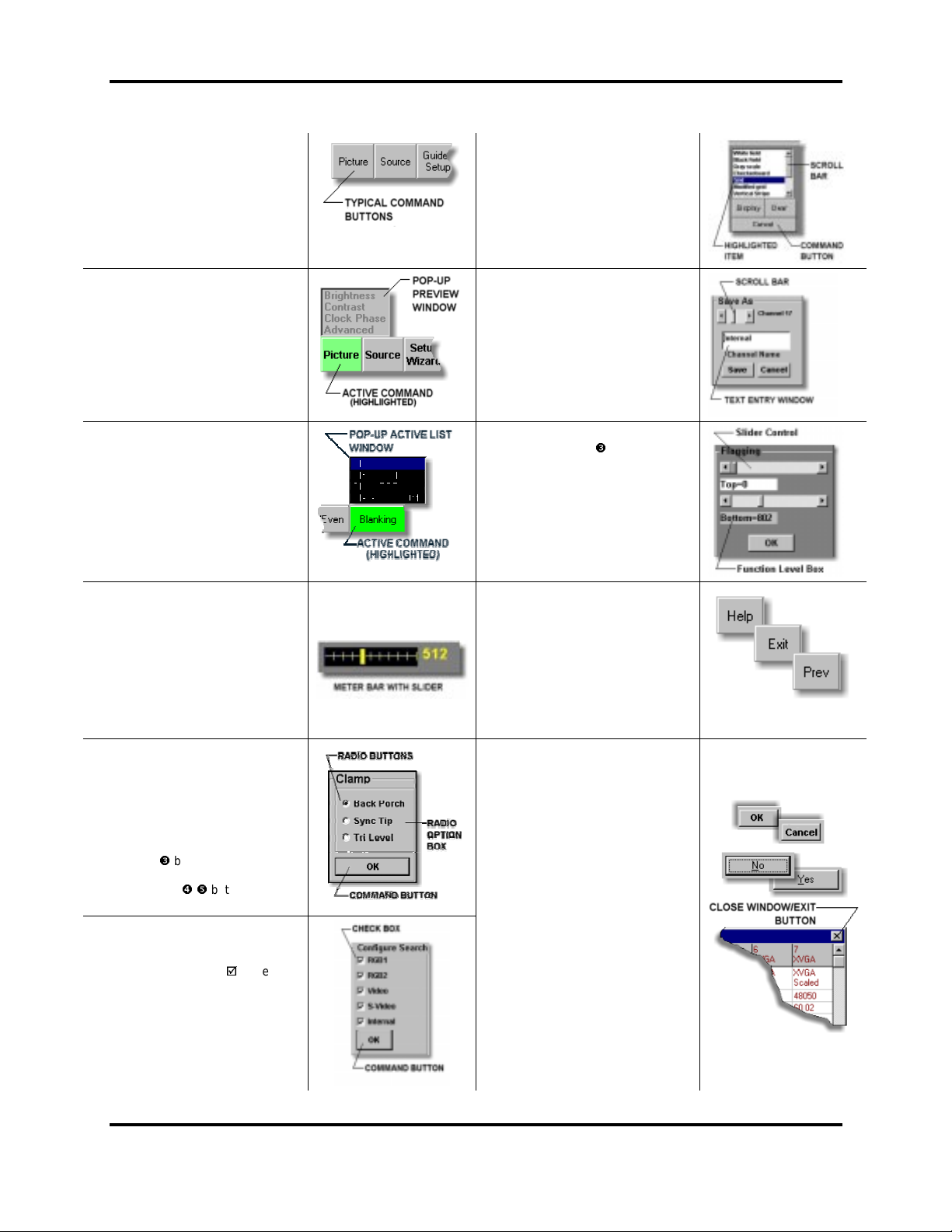
Menu Navigation and Conventions
Command Butto ns –
buttons c aus e an ac ti on t o occ ur,
such as sel ect ing a partic ul ar
function or presenting a
supplementary dialog box
Command
Basic Operation and Menu Navigat ion
List Box –
item from a list. Scroll bar - Use the
scroll b ar typical ass oc i ated wi th lis t
boxes to m ov e up an d d ow n th e lis t.
An item that is highlighted is
available for selection.
Allows you to select an
Pop-Up Preview Windows –
Up preview windows are associated
with some command buttons. The
preview window all ows y ou t o view
the perspective controls and
functions relevant to the initial
Pop-Up Active Lis t Window –
up Active list w in d ows al l ows th e
user to select a function directly form
the smaller pop-up window. Typically,
when scrolling through the pop-up
Meter Window/ Bar –
is made available to those functions
that requir e an adjustm ent be made.
Additionally, use the remote mouse
point and cl ic k t o dr ag th e sl id er.
Radio Buttons –
choices. You must pick on of the
choices b y eith er m ouse clickin g or
using the remote control or keyboard
arrow keys t o sel ec t the associ at ed
Use the button or <Tab> key t o
command. Use / buttons to m ove
Check Box es –
particular command option, select
multiply choice items. The option is
enabl ed wh en a ch ec k appears in
the check box. The item is disabled
window, the function is
simultaneously highlighted and
The meter bar
Use either the Adjustment Pad
(remote) or the arrow keys
(keyboard) to perform the
Used to present
two or more mutu ally exclus i v e
button to hig hlight.
move bet w een opt ion box an d
between op ti ons
Enabl e/disable a
when the check box is empty.
Pop-
command.
Pop-
activated
adjustment.
Text Entry –
a text entry is r equ ir ed. O n e exam ple
of this function is the Channel“ SAVE
AS”. Place the cursor into the text
entry window and use the keyboard
to type or edit th e exis t ing text stri n g.
Pop-Up Functions with Slider
Controls –
<Tab> key t o m ove b etween func ti on
level box and commands. When the
relevant fun ction leve l box is
highlighted, use the remote
adjust m ent p ad or k eyboard arrow
keys to adjust.
command is m ad e availab l e on all
command is used to revert back to
Allows you to exit the menu system
and removes the on-screen display.
OK Button–
your choice and return to the initial
Cancel Button -
windows include the Cancel button.
Click this button to cause ALICE to
ignore an y ch anges you’ve made to
Yes/No Buttons –
are normal l y associat ed with dec is i on
Close Window and Exit Button –
On some of the menus y ou w il l fin d
the Close/Exit button, these controls
are typic al associ ated wit h
inform ation only wi nd ows
With certain operations
Use the button or
Help -
Enters this help file . This
menu screens.
Prev –
Previous command. This
preceding command bar.
Exit –
Avail ab l e on all screens .
Click this button to ent er
command.
The majority of the
the function and return to the
windows. Yes will accept the
command and No will cancel
previous op eration
These commands
command .
17
5200 User’s Manual
Page 20
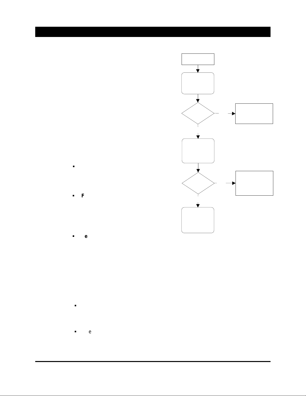
Auto Search
Auto Search & Temp Channel
When a new source is introduced t o the
projector, t he pr ojec tor will initially search
through the “
match. If a match is found, this channel is
selected and the channel number is
displayed in the “Chan n, Select Channel”
command button located on the initial menu.
If no match is found in the “user” channel
listings, then auto-search will look t hr ough
factory
the “
match. If a match is found, then this is
selected and the channel number displayed
in the “Chan n, Select Channel c ommand
button is set to 0 (zero).
user
” channel listing for a
” read-only channel data for a
Auto Search Flow
New Source
Search "
channel data
for match
Find
Match
user
"
YES
Select match.
Display channel
number
Saving
Temporary
Channels
If no match is found in the factory channel
NO
listing, then t he pr ojec tor will interpol ate
between the next closest signal above and
below the current signal and establish a
temporary
channel. Again, di spl ayi ng 0
(zero) as the selected c hannel number.
User Channel List
The “user” channel list contains all user
established channels setups and some
common source setups from the factory.
Factory Channel List
Search
"
channel data
for match
factory
Find
Match
NO
"
YES
Select match.
Display channel
number "0"
(temp channel)
The “factory” channel list is a read-only
listing that is or iginally crea ted at the factory
and cannot be acces s ed d irectly b y the
user. This list contains a variety (100+) o f
common video and co mpu ter s etups.
Temporary Channel
Interpolate.
Establish
"
"
temp
channel.
A temporary channel is deno ted as a
channel that has e ither been cop ied from
the factory channel list or a new channel
created by system interpolation. A temp
channel is designated as Chan nel 0 (zero).
The temporary channel is never changed unless the user has changed at least one
parameter, i.e., Brightness, Contrast, H P os etc.
Now assuming that at least one parameter has been changed, the tem por ar y c hannel is
saved under either of t he two foll owing two circumstances;
At least 10 minutes has passed since the most recent change. This 10-minute timer is reset
every time a parameter change is made. If the temporary channel is saved under this condition,
a new channel is created and the projector is switched to this new channel. The new channel is
set to the next open channel number and is tagged with the horizontal and vertical frequencies.
A temporary channel is saved if any action is taken that causes a new or different channel to be
selected. This includes such actions as selecting a new channel manually, selecting a new source
manually, changing the input source so auto search forces a channel change, selecting this Help or
Edit Config, which both forces selection of the internal channel.
18
5200 User’s Manual
Page 21
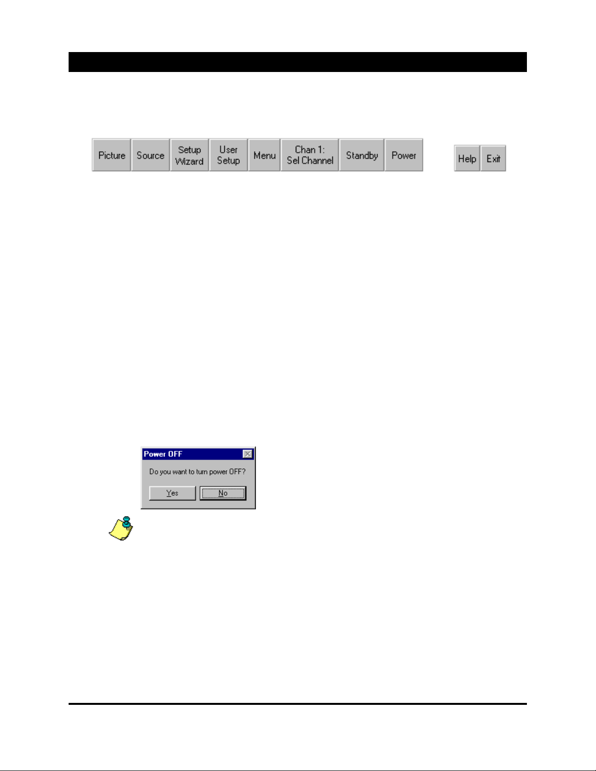
Menu System
As previously menti oned, ALICE operates on layer s of c ommand but ton menus. The initial command
buttons (below) allows you to access all of the user type projector controls.
Main Menu
Picture
Source
Setup Wizard
User Setup
Menu
Chan 1: Sel
Channel
Standby
Power
Allows the user to adjust im age quality functions such as, bri ghtness, and contrast, cl oc k
phase and some advance settings as well.
Allows the user to expli ci tly select the display source type. I.E., RGB, RGB2, VIDEO etc.
The Setup Wizard all ows the user to step thr ough pr edetermine setup sequence. This is
useful for the first time user.
This function allows you t o perform a random type of channel setup or editing. This is
typically used by exper ience operators
Menu presents additional commands and functi ons for the setup of a source (channel).
This button display s the c ur r ently active channel. Once selec ted, a channel list dialog box is
presented for manual sel ec tion of a desired channel setup.
In the case of
incoming signal and has ei ther selected a setup from the “factory channel data” which is a
read-only li st or has int er polated between the existing channels and has established a
temporary channel. See Auto-Search for operation and saving temporary c hannels.
Puts the projector into the standby mode. Powers the lamp suppl y off . If y ou ar e usi ng an
external monitor for projector operation, press STANDBY to re-display t he im age. Also, see
Remote Control operat ion.
Chan 0:
Chan 0 indicates that the projec tor did not find a match for the
Powers the project or ( Displ ay engine/Lamp) OFF. Presents
the user with a decision dialog box. In the event this command
was entered intentionally, simply select NO on dialog box.
Help
Exit
Important: It is recommended to leave the main AC power applied and the main AC sw itch
be left in the “on” position. If the main AC power is to be removed, allow a minimum of 2
minutes after engine shutdown before removing AC
Enters this help file.
Exits the menu system and r em ov es the menu(s) fr om the screen.
.
19
5200 User’s Manual
Page 22
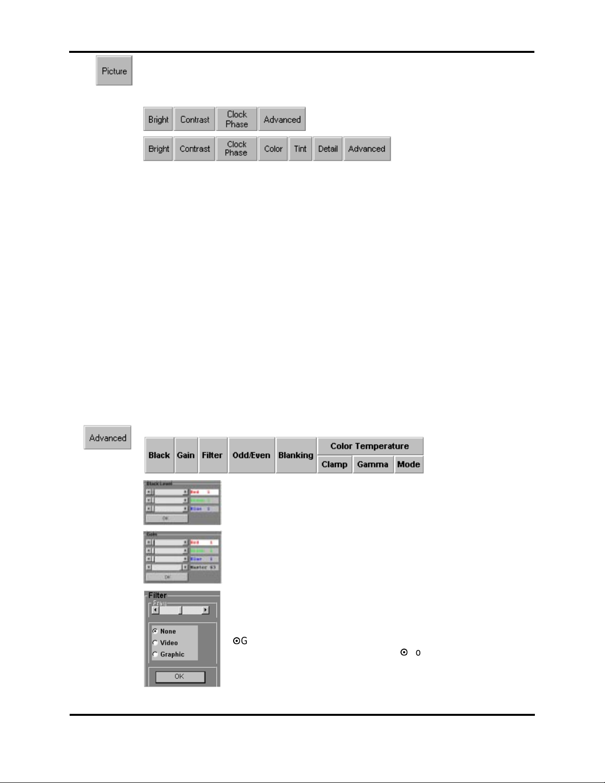
RGB MODE
VIDEO MODE
Menu System
Picture Command - The user is provided with a new set of command controls. The
numbers of contr ols are depended on t he par ticular mode, i. e. RGB ver sus Video. These
controls are used to adj ust the image quality of the projec ted image, with additional adv anc e
controls for blac k l ev el, gain, filter, odd/even setting and blanking.
Bright
Contrast
Clock Phase
Color
(Video Only)
Tint
(Video Only)
Detail
(Video Only)
Advanced
Adjust the bright ness level until the black porti ons of the projected image are black, buts
details in the shaded areas are not lost. Selecti on c alls out the Meter/Slider adjuster.
Contrast will change t he am ount of intensity. Adjust cont r ast for the desir ed r esul ts.
Selection calls out the Meter/Slider adj uster .
Adjust the timi ng of the pixels from the computer to match the ti m ing of the pixels on the
projector. Pr oper adjustment will give sharper ver tical lines by using one pixel on the
projector for si ngle pixels coming from the computer . Selection calls out the Meter/Sl ider
adjuster.
The color functi on c ontrols the color saturation of t he im age. If the image appears too pale or
weak, increase the col or lev el. If the color image appears fl ushed or t oo bril liant, decrease
the color level. T his selections calls out the Met er/Sl ider adjuster.
The tint control f unction controls the hue of the vi deo im age. If facial tones or objects appear
too green, increase the t int setting. If facial t ones appear t oo pur ple, decrease the tint level.
This selections cal ls out the Meter/Slider adj uster .
The detail functi on c ontrols the sharpness of the vi deo im age. If the image appears too soft,
increase the detail level. If the image appears too grainy, decrease the detail lev el. T he
desired setting of the det ail function, set det ail as hi gh as possible without the image
appearing grainy . This selections calls out the Meter/Slider adjuster.
Evokes an additi onal function button bar. Under the Advance command the following
functions are available:
Black
Gain
Filter
Use the Black Level Cont r ol Panel to individually adjust the am ount of
background bright nes s until the desired effec t is achi ev ed.
Use the Gain Control Panel to adjust the amount of image intensity for
the indivi dual c olor s. Use the M AST E R to adjust t he am ount of ov er all
gain.
This function is utilized to pre-filt er the inc omi ng si gnal. Primarily used
when the incoming signal is greater than the nativ e resolut ion of 1024 x
768 and system level image scaling is required. When the inc omi ng
RGB video signal resolut ion is greater than the nativ e r esol ution, Select
Graphic mode and set the f r equenc y for best ov er all v isual
performanc e. Although typically set t o None, the Video filter may be
used to clean up a noisy incoming si gnal. Select the desired opti on from
within the opti on dialog box presented.
20
5200 User’s Manual
Page 23
Advanced “continu ed”
Menu System
Odd/Even
Blanking
Color
Temperature
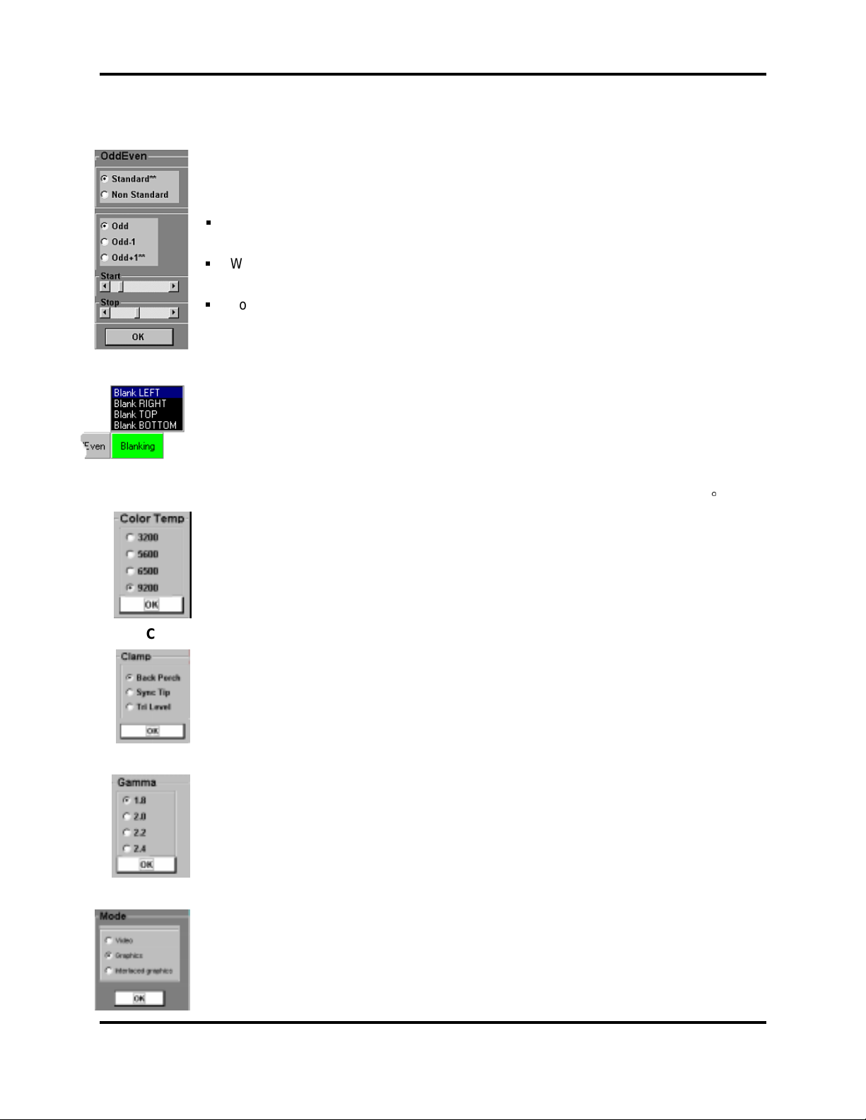
Certain signals may require you to set the ODD/EVEN parameters. Once selected, you are
presented with an option box for selection. If y our image appears j agged or the fields are
offset or seem out of order, switc h between STANDARD or NON-STANDARD mode. The
setting of the ODD, ODD PLUS 1 and ODD MINUS 1 is only available when NONSTANDARD mode is selected. Primarily used for interlac ed sources.
The START parameter is used to set the low end of the detection range, whic h is
typically set to 25% of image resolution.
While the STOP parameter is used to set the high end of the detection range, and is
automatic ally set to 75% of the im age r esol ution.
For non-interlaced the START/STOP command is ignor ed
The 5200 provides’ the ability to blank out the image on all f our si des. The purpose of the
blank control is to r em ov e any unwanted or useless i nformation at the t op, bottom, left and
right sides. Once Blank ing button is highlighted, a pop-up active list window appears.
The 5200 provides’ the ability to select between 4 standard col or temperatures. The pop- up
option box includes the f ollowing color temper atures; 3200, 5600, 6500 and 9200 K.
Clamp
Gamma
Mode
Select the required black level clamp point. Sel ect between “Back porch” (typically
associated with Video or RGB 3-wire) or “Sync tip” ” (typically associated with RGB 4/5-wire)
or “Tri-Level” ” (t y pic ally associated with HDTV) mode of operation on a channel-to-c hannel
basis. See Clamp pop-up opt ion box.
Traditionally, Gamma correction is used to compensate for the non-linear r esponse of
Cathode Ray Tubes (CRT’s). Since the 5200 projector inc or por ates the DLP technology,
where the DMD’s have a linear response, the Gamma signal that is used in standard
broadcast signals must be r em ov ed. There are 4 different setti ngs i n the pop-up option box
for the Gamma removal. S elec t t he best option for optimum low end or black level.
There are three (3) modes or processing choices for sel ection through the pop-up option box.
The Video mode uses the built-in
The
Interlaced Graphics
MAPS or Field Jam correction method.
mode applies Filed Jam and the
Motion Adaptive Pr ogr es s iv e Scan
Graphics
mode uses neither the
(MAPS) conversation,
21
5200 User’s Manual
Page 24
Menu System
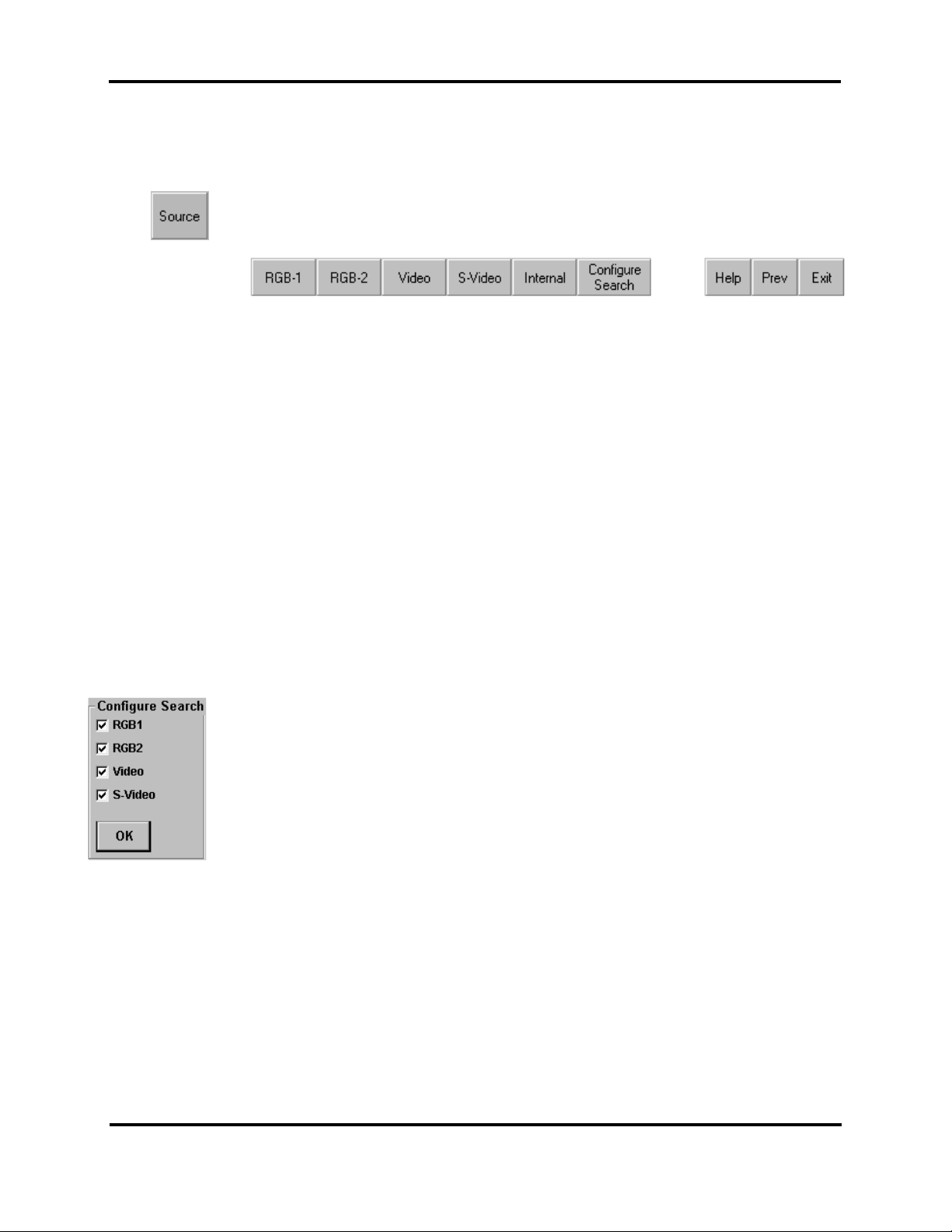
Source Command - Is used to select the desired input or display mode. Wit h all av ailable
options install ed, the user may select between two (2) RGB modes, two (2) Video modes and
the internal gr aphic s mode.
RGB-1
RGB-2
Video
(optional)
S-Video
(optional)
Internal
Configure
Search
The RGB-1 input incl udes separate connec tors for RED, GREEN, BLUE vi deo si gnals, plus
separate connectors f or Com posi te Sync (Horizontal Driv e in the case of five (5) wire inputs)
and Vertical Drive.
The Analog RGB input falls into three major categories, three-wire with sync-on- gr een, fourwire with composite sync and five-wire with separate hor izontal and vertical dr ives. The
AmPro 5200 will automati c ally configure itself proper ly for any of the above conditi ons,
including sync input and polarity.
An HD15-pin connect or is provided for direct connection to a VGA/SVGA and XGA from an
external PC.
he Video input is provi ded through either the internal Faroudja Decoder or the internal AmPro
quad video decoder. The AmPro quad decoder will automatically works with Composit e
NTSC, NTSC 4.43, PAL or SECAM.
A secondary input t o either the above mentioned decoders i s the S - Vi deo input. This input
uses a 4-pin mini Din connector , which is standard for this input.
Refers to the internal gr aphics card and Windows 95® operation. When no external source is
available or r equir ed, switch to the internal mode of operation
The configure search command enables a check box dial og window (l eft) where you have
the option of selecting which source the proj ector will search if no signal is applied or a lost of
signal occurs.
22
5200 User’s Manual
Page 25
Menu System
Setup Wizard
Main Screen
and Functions
H Pos
Pixel Clock (N)
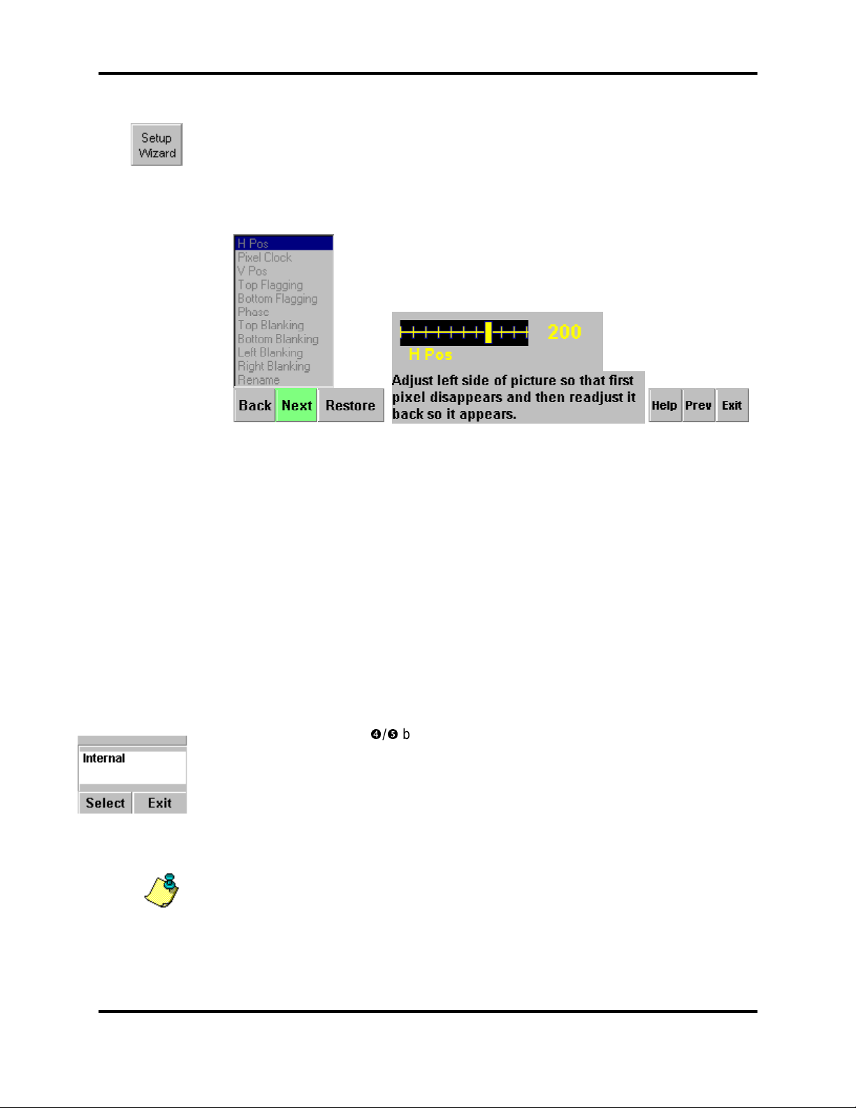
The SETUP WIZARD will guide the fi r st time user through a step-by-step setup of the various
image parameter s or even if you ar e an ex peri enc e user, the Setup Wizard provides a qui ck
method of setting up a new source.
The Setup wizard screen prov ides you with the function list. Use the Back/Next buttons to
move through the list. The Setup Wizard screen also provi des the adjust meter along with
brief function instr uc tions. The restore button resets the currently active function.
Centers the active video area within maximum display ar ea. Adjust for minimal image loss
from side-to- si de. Set t he star t point of the image on the left side. Adjust until the left edge of
the image is just visi ble, but not cutoff.
Reduces or eliminat es vertical banding and foc us problems by adjusting the length of each
horizontal line to match the computer line length. Adjust until the right side of the image
matches the display si z e or is not cut off by the border .
V Pos
Top Flagging
Bottom
Flagging
Blanking
Rename
Restore
Centers the active video area within maximum display ar ea. Adjust for minimal image loss
from top- to -b o ttom.
Reduces the image flagging, tearing or jitt eri ng at t he top of the image.
Reduces the image flagging, tearing or jitt eri ng at t he bott om of t he im age.
TOP, BOTTOM, LEFT, RIGHT - Use the blanking f unc tions in case of wanted (active) vi deo
informati on is cut off or to elimi nate any unwanted (non-active) video inform ation. Use the
blanking f unction for the top, bottom, left and ri ght unt il the desired effect is achi ev ed.
Once all parameters have been made and satisfied, use the RE NAME function to name your
source. Use the <TAB> or / buttons until the text window is hi ghlighted. Use the
keyboard to enter a new source nam e. Using the keyboard, ent er the desi red channel name
or press [Select] to acc ept t he default name. Will overwrite exi sting channel name
Use this functi on to undo t he last c hanges prior to the last save. See Note below
NOTE: Channel data is saved when one of the f ollowing conditions occ ur s;
1.) 10-minutes aft er a change has been made, providing no other changes ar e m ade within
the 10-minute save window.
2.) A new channel has been selected, or an action oc c ur s whic h s elec ts a new c hannel or
source
3.) An explicit “Save As” comm and has been per formed.
23
5200 User’s Manual
Page 26
Menu System
User’s Setup
H Pos
V Pos
Pix Clock
Clock Phase
Border
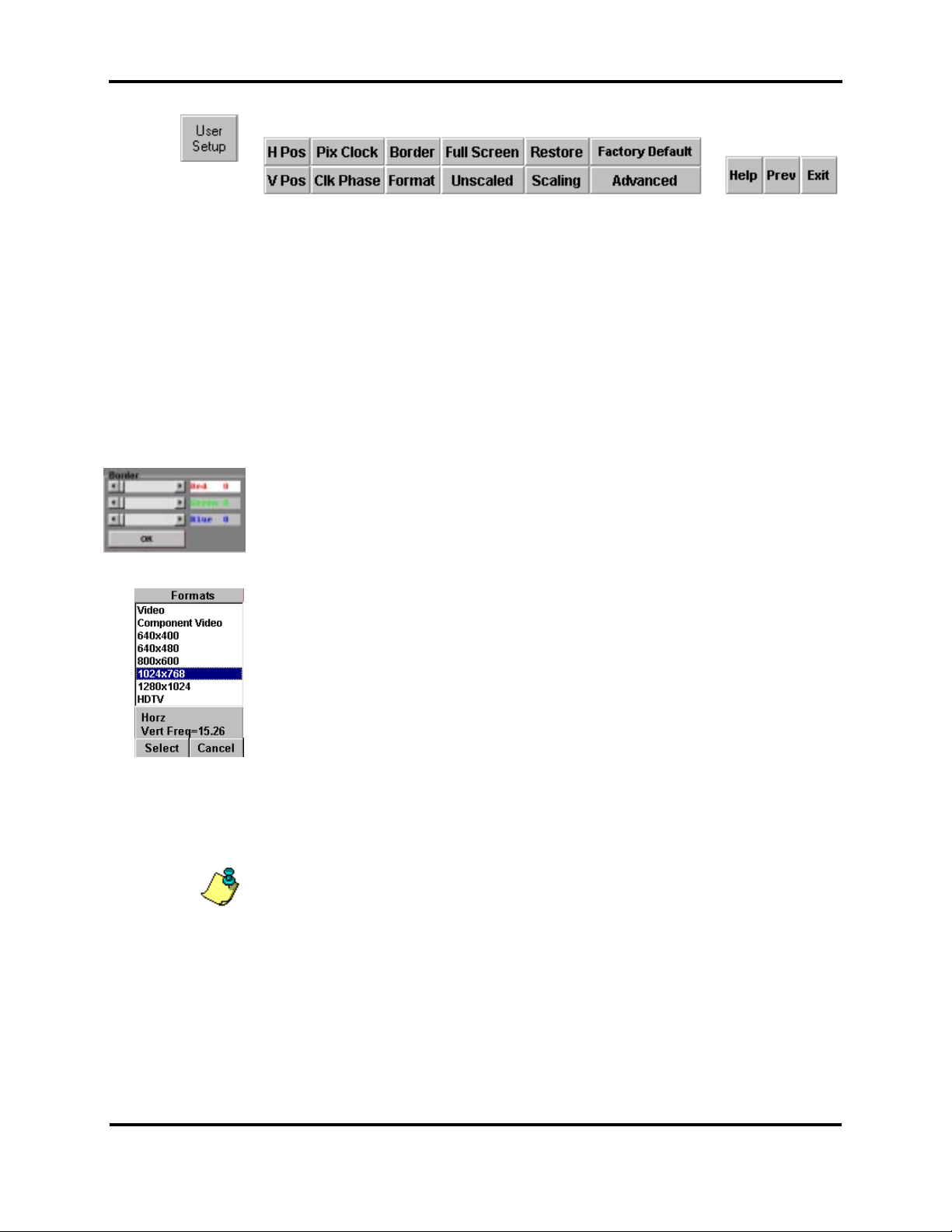
The User Setup command allows random access the setup control s of the projector.
The more experienced operator typically uses thi s func tion.
Centers the active video area within maximum display ar ea. Adjust for minimal image
loss from side-to-si de. Set the start point of the image on the left side. Adjust until the
left edge of the image i s just visible, but not cutoff.
Centers the active video area within maximum display ar ea. Adjust for minimal image
loss from top-to- bott om .
Reduces or eliminat es vertical banding and foc us problems by adjusting the length of
each horizontal line to match the computer line lengt h. Adjust until the right side of the
image matches the displ ay si z e or is not cut off by the border .
Adjust the timi ng of the pixels from the computer to match the timing of the pixels on the
projector. Pr oper adjustment will give sharper ver tical lines by using one pixel on the
projector for a si ngle pix el c omi ng from the source.
The border command evok es the bor der c ontrol panel. The user can set the color of the
border to either on of the primary colors or virtuall y any com bination of them. The border
is useful for centering sources that are less than the maxim um 1024 x 768 resolution
onto the screen.
Format
Full Screen
Unscaled
Restore
Use the Format command to select the closest matching form at of the inc omi ng si gnal
from the List dial og box.
This command scales the inc omi ng si gnal to the maximum resoluti on of 1024 x 768.
This command selects the signals original r esol ution for displays or changes a scaled
signal back to its ori ginal r esol ution.
Use this functi on to undo t he last c hanges prior to the last save. See NOTE below.
NOTE: Channel data is saved when one of the f ollowing conditions occ ur s;
1.) 10-minutes aft er a change has been made, providing no other changes ar e m ade
within the 10-minut e s av e window.
2.) A new channel has been selected, or an action oc c ur s whic h s elec ts a new c hannel
or source
3.)
An explicit “Save As” comm and has been per formed.
24
5200 User’s Manual
Page 27
User’s Setup “continued”
Menu System
Scaling
Factory Default
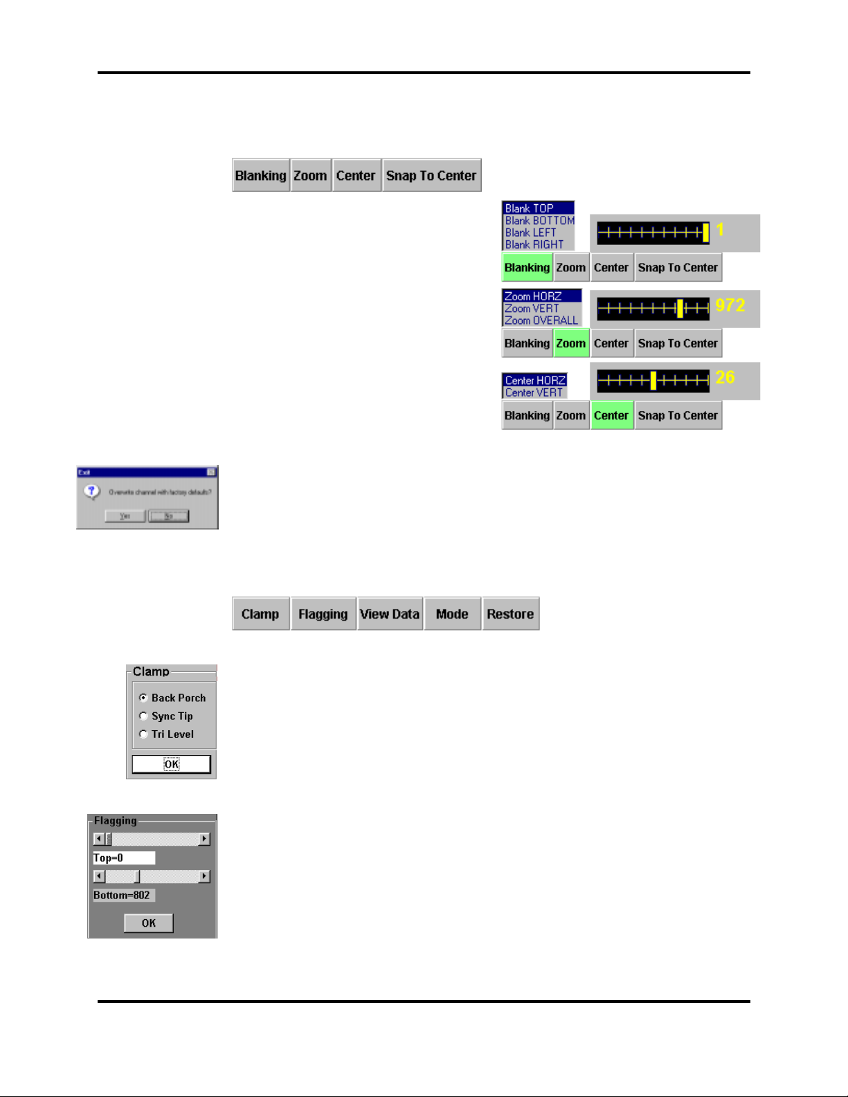
Provides the user with t he ability to blank all four sides, Size or “zoom” the image in the
horizontal, v ertic al or both directions, cent er the im age hori z ontally, vertically or snap
the image to horizont al/vertical centers. S ee S c aling c ontrols.
Blanking - Adjust the four sides of the
image until all unwanted v ideo is
eliminat ed or wanted information is
visible.
Zoom – Adjust the image size in the
horizontal, v ertic al or both directions until
optimal or desired effect is achieved.
Center – Center the im age hori z ontally,
vertically or snap the image to
horizontal/vertical centers.
This command changes the cur r ent channel to predetermined factory default. Once
evoked, the user is presented wit h a c onfirmation widow. Once ov er wri te is selected, all
previously channel changes will be lost.
Advanced
Clamp
Flagging
Evokes an additi onal function button bar. Under the Advance command the following
functions are available:
Select the required black level clamp point. Sel ect between “Back porch” (typically
associated with Video or RGB 3-wire) or “Sync tip” ” (typically associated with RGB 4/5wire) or “Tri-Lev el” ” (typically associated with HDTV) mode of operation on a channelto-channel basis. S ee Clamp pop-up option box.
Reduces the image flagging, tearing or jitt eri ng at t he top and/ or bottom of the image.
Once selected the Flagging adjustment pop-up window is pre sented.
25
5200 User’s Manual
Page 28
User’s Setup “continued”
Advanced “continu ed”
Menu System
View Data
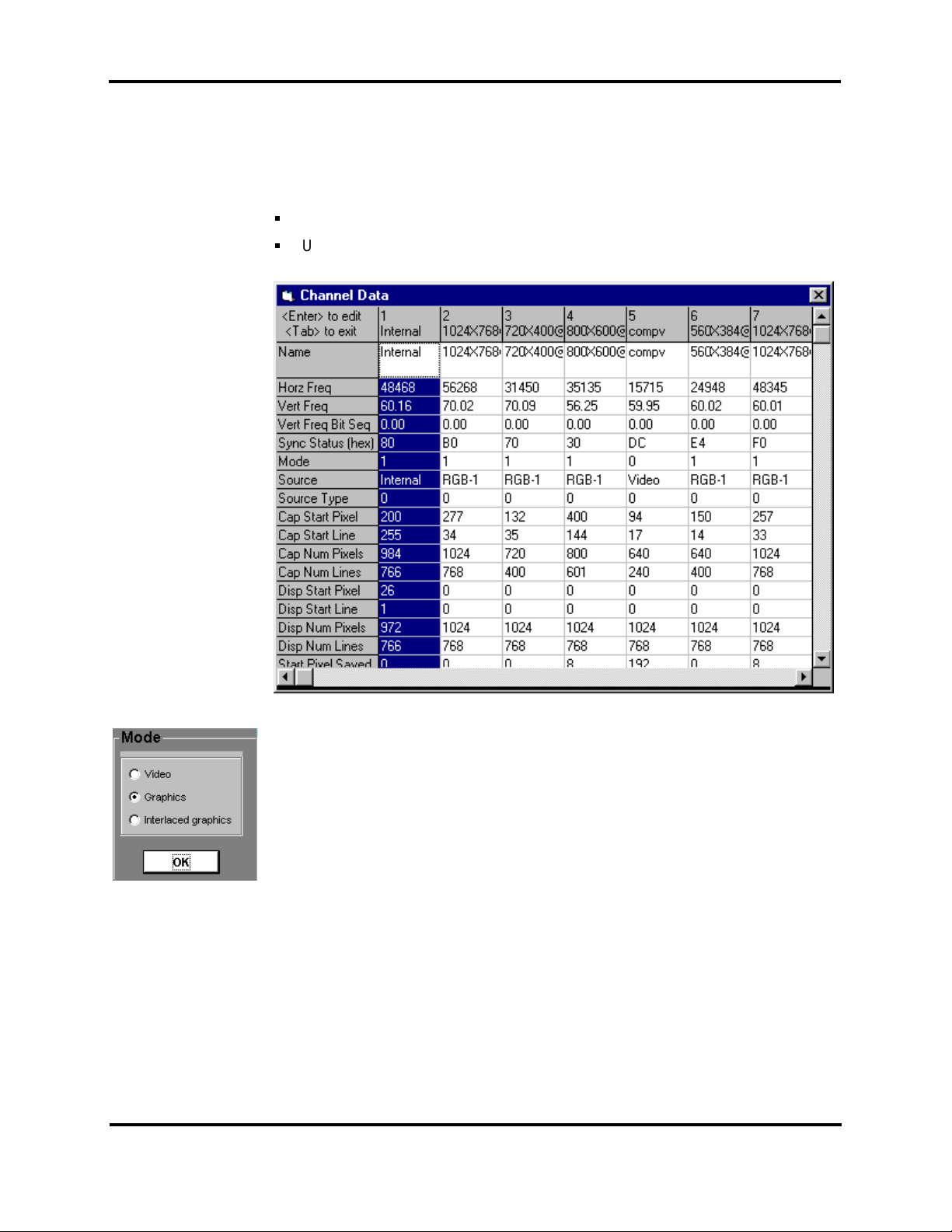
The View Data provides a comprehensive listing window of all of t he user channels.
This listing i ncl udes all the statistics that mak e- up a partic ular channel.
The Highlighted column denotes the currently sel ec ted channel.
Use the scroll bars at the bottom and right sides to move up-and-down or l eft-to-
right.
Mode
Restore
Menu Command
There are three (3) modes or processing choices for sel ection through the pop-up
option box. The Video m ode uses the bui lt-in
(MAPS) conversation, The
Graphics
See Restore above
mode uses neither the MAPS or Field Jam correc tion method.
The Menu command provides addi tional access to the channel m anagem ent
system and to the projector utility area.
Interlaced Graphics
Motion Adaptive Progress iv e Scan
mode applies Filed Jam and the
26
5200 User’s Manual
Page 29
Menu System
Menu-Channels
Select
Save As
Copy
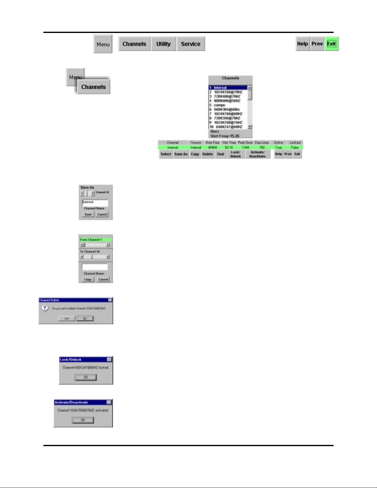
Use the Channels command t o access the channel m anagement system with the
following functions.
Highlight the desir ed c hannel, then press Select to choose the c hannel for display.
First highli ght t he desi r ed c hannel, then press Save As to evoke the Save As pop-
up window. The Save As command will automatically selec t t he next open c hannel
number.
The Copy command provides the ability to copy from channel to anot her . O nc e
chosen, the Copy pop-up window is provided which allows you to dir ec t from where
you want to copy from to where you want to c opy to.
Delete
Find
Lock/Unlock
Activate / Deactivate
The delete command allows you to remove any unwanted or duplicate channels.
Once selected a deleti on c onfirmation window will presented, allow you to accept
the deletion proc ess or abort the operation.
This function will first, turn on Au to-Search , then automatically “find” a new channel and
turn Auto-search back o ff. I f Auto-Sea rch is already “on”, th is function has no effect.
This channel prov ides the ability to lockout any changes to c hannel settings. Press
this command to toggle the Lock/Unlock operation. The status of the Lock/Unlock
function is di spl ay i n the main Channel command bar (above). Onc e activ ated a
confirmation window will appear.
This command allows you to rem ov e the desir ed c hannel or channels from the lookup list used by the Auto-S ear c h function. If a channel is tagged “deactivated” then
Auto-search will bypass this particular channel during the Auto-Sear c h pr oc ess.
Use this button to toggl e the stat e of the highlighted channel. The user will be
presented with a confi rmation window.
27
5200 User’s Manual
Page 30
Menu Command “continued”
Menu System
Menu-Utility
Orient
Freeze
Patterns
Configure
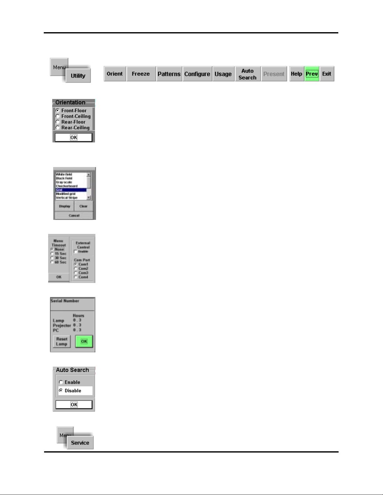
Several projector set-up and configuration commands are found under the Utility
command.
Allows the user to select the desir ed pr ojection appli c ation for the following modes.
Front-Floor , Front - Ceiling, Rear-Fl oor and Rear-Ceiling. Press the Orient butt on to
access the pop-up opti on box .
Toggle Function. Use the Freez e c ommand to freeze the motion of the proj ected im age.
Use the Patterns command t o displ ay a v ari ety of t est patt er ns or your own bitmap
images. See Patterns Li st B ox .
The configure options al lows the user to set some additional operating paramet er s of the
projector. Par am eters such as, Menu Timeout, Enabl e Ext er nal RS 232 c ontrol and
selecting which c ommunication port to use.
Usage
Auto Search
Menu-Service
Usage provides the user with t he pr ojector’s serial number and elapsed time on the
Lamp, Projector and P C. When installi ng a new lam p, reset the lamp elapsed time. See
Usage items.
The Auto-Searc h option box allows the user to enable or disabl e the Auto-Search mode
of operation.
Password Required
Only qualified per sonnel use the S ervice command.
28
5200 User’s Manual
Page 31
Menu System
Chan 1:
Sel Channel
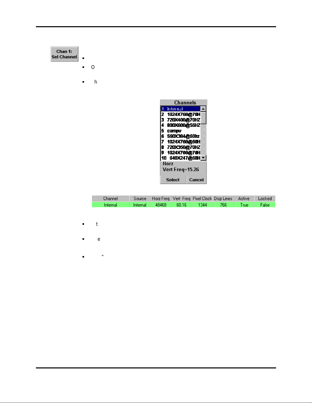
Chan n: Indicates the selec ted channel. Where “n” is the channel number.
NOTE: Chan 0 indicates a temporary channel* has been created.
Sel Channel: Press button to activate a channel li st box . See below
Use the scroll bar on the right si de to mov e up and down the list.
Once a channel is highlighted in the list window, use the Select button to choose the
channel for display.
The channel information bar at the bottom displays the mor e c ri tical channel
parameters.
* Temporary Channel
A temporary channel is denoted as a channel that has either been copied from the
factory channel** list or a new channel created by system interpolation.
A temp channel is designated as Channel 0 (zero).
** Factory Channel List
The “factory” channel list is a read-only listi ng that is originally created at the factory
and cannot be accessed direc tly by the user. This list contains a variety (100+) of
common video and computer setups.
29
5200 User’s Manual
Page 32
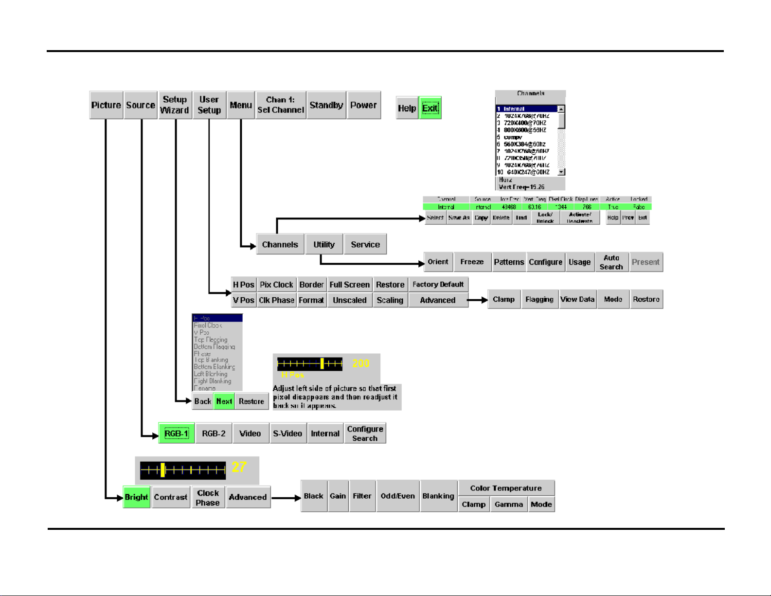
Menu Overview
Menu System
30
5200 User’s Manual
Page 33
Installation, Lens Adjustments & Lens Data Tables
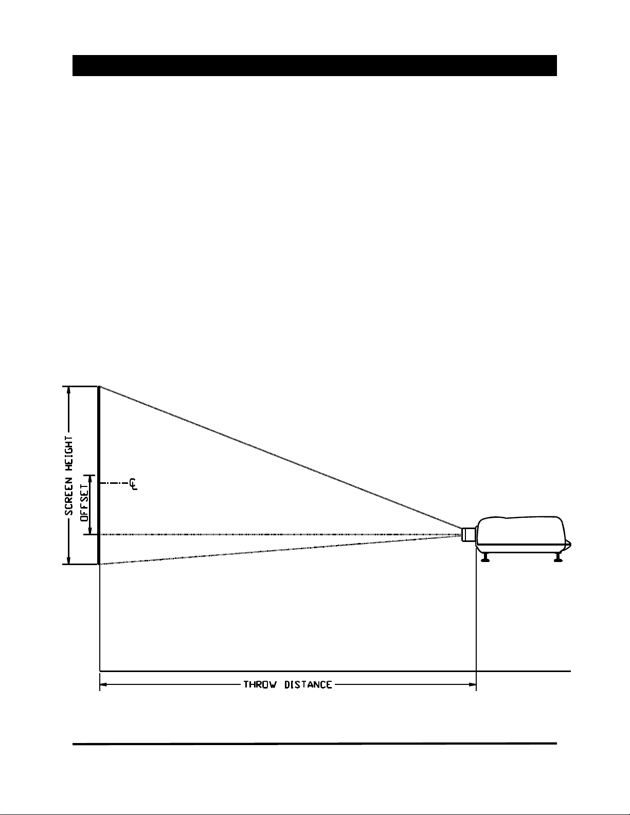
Throw Distance
Projector Offset
The projector has a wide v ari ety of lenses available, including multiple fixed and z oom s.
Refer to Lens Data Tables.
The throw distance i s calculated by using the lens magnification factor times the desir ed
image width.
The 5200 has the ability to dynamically scale the incom ing si gnal ( r esol ution) to the full DMD
resolution of 1024 x 768. This simply means that all sources can utilize the full resolution
capabilit y so image width should be lost. However, if y our signal resolution is not equal to or
greater than the DM D resoluti on and y ou do not scale to the full DMD resoluti on, image width
and/or size will be smaller the actual screen size.
The projector incor por ates a manual lens shift capability allowing a vertical (up- down)
adjustment of the lens without moving the projector.
The maximum offset of the pr ojec tor depends on;
1.) type of lens
2.) image height
Refer to the Fixed and Zoom Lens Data T ables.
31
5200 User’s Manual
Page 34
Optical Adjustmen t s
Installation, Lens Adjustments and Lens Data Tables
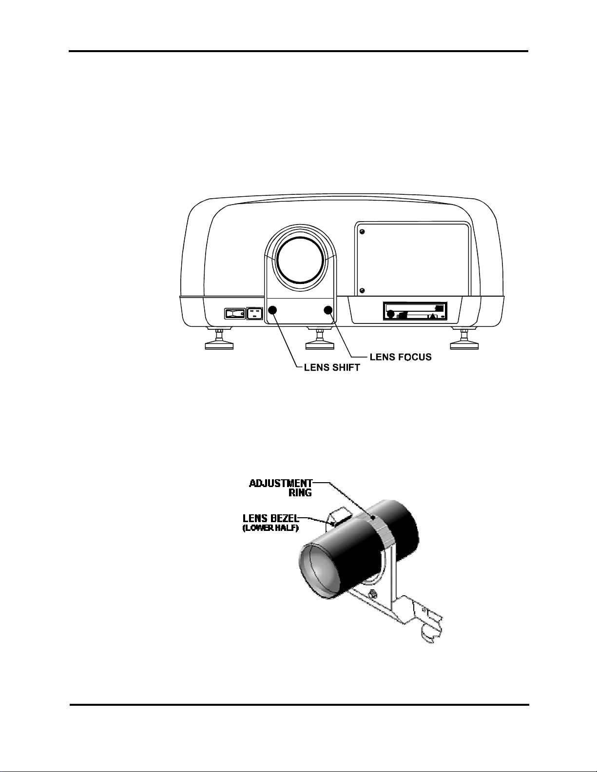
Lens Shift
Adjuster
Lens Foc us
Adjuste r
The lens shift is adj usted by turning the lens shift knob locat ed at t he front of the projector.
Adjust the lens shift until the image is centered wit hin y our screen area. S ee B elow. Refer to
the Lens Specifications for the maximum amount of lens shif t for your particular lens.
To focus the image, turn the lens focus knob (near the lens shift adjuster ) to fine tune the
lens focus. Adjust the knob until optimal focus i s achieved. See Figure below.
Zoom Lens
Adjustm e nt
Open the top cover to access the zoom lens adjustment ring. The top cov er m ay be unlocked
by turning the two ¼ turn captive screws on both sides on the projector, close to the front of
the project or. The actual adjustment ring is under the lens bezel. Grab the gray ring around
the lens and rotate it back-and-forth until the proper or desired image size is achieved. See
Figure below. Refocus the lens if necessary.
32
5200 User’s Manual
Page 35
Installation, Lens Adjustments and Lens Data Tables
Fixed Lens Data Table
Data presented in the follo wi ng tables are for reference use only!
1.0:1 Lens Specifi cat io n/Throw Distance (Referen ce Only)
Throw Distance: 4.6 ft. ( 1.4 m) - 30 ft. (9.1 m) @ 4:3 Ratio
Pixel Vertical Off set @ 1024 x 768 = +/- 150 pi xels
Image Size
Width Height Diagonal
in. mm in mm in. mm in. ft. m
55 1397 41.3 1048 68.8 1746 55.0 4.6 1.4
80 2032 60.0 1524 100.0 2540 80.0 6.7 2.0
120 3048 90.0 2286 150. 0 3810 120.0 10.0 3.0
180 4572 135. 0 3429 225.0 5715 180.0 15.0 4.6
240 6096 180. 0 4572 300.0 7620 240.0 20.0 6.1
360 9144 270. 0 6858 450.0 11430 360. 0 30.0 9.1
2.3:1 Lens Specifi cat io n/Throw Distance (Referen ce Only)
Throw Distance: 17.2 ft. (5.5 m) - 110.4 ft. (33.6 m)
Pixel Vertical Off set @ 1024 x 768 = +/- 150 pi xels
Image Size
Width Height Diagonal
Throw Distance
Throw Distance
in. mm in. mm in. mm in. ft. m
90 2286 67.5 1715 112.5 2858 207 17.3 5.3
102 2591 76.5 1943 127. 5 3239 235 19. 6 6.0
128 3251 96.0 2438 160. 0 4064 294 24. 5 7.5
256 6502 192. 0 4877 320.0 8128 589 49.1 15.0
358 9093 268. 5 6820 447.5 11367 823 68.6 20.9
576 14630 432.0 10973 720.0 18288 1325 110.4 33.6
Preliminar y
33
5200 User’s Manual
Page 36
Installation, Lens Adjustments and Lens Data Tables
Fixed Lens Data Table “continued”
Data presented in the follo wi ng tables are for reference use only!
3.9:1 Lens Specifi cat io n/Throw Distance (Referen ce Only)
Throw Distance: 19.0 ft. (5.8 m) - 118.0 ft. (36.0 m) @ 4:3 Ratio
Pixel Vertical Off set @ 1024 x 768 = +/- 150 pi xels
Image Size
Width Height Diagonal
in. mm in. mm in mm in. ft. m
58 1483 43.8 1113 73.0 1854 228 19.0 5.8
80 2032 60.0 1524 100.0 2540 312 26.0 7.9
96 2438 72.0 1829 120.0 3048 374 31.2 9.5
120 3048 90.0 2286 150. 0 3810 468 39. 0 11.9
240 6096 180. 0 4572 300.0 7620 936 78.0 23.8
363 9220 272. 3 6915 453.8 11525 1416 118.0 36.0
5.5:1 Lens Specifi cat io n/Throw Distance (Referen ce Only)
Throw Distance: 26.0 ft (8.0 m) - 164.0 ft. (50.0 m) @ 4:3 Ratio
Pixel Vertical Off set @ 1024 x 768 = +/- 150 pi xels
Image Size
Width Height Diagonal
Throw Distance
Throw Distance
in. mm in. mm in mm in. ft. m
60 1524 45.0 1143 75.0 1905 330 27.5 8.4
80 2032 60.0 1524 100.0 2540 440 36.7 11.2
100 2540 75.0 1905 125. 0 3175 550 45. 8 14.0
120 3048 90.0 2286 150. 0 3810 660 55. 0 16.8
180 4572 135. 0 3429 225.0 5715 990 82.5 25.1
240 6096 180. 0 4572 300.0 7620 1320 110.0 33.5
358 9093 268. 5 6820 447.5 11367 1969 164.1 50.0
Preliminar y
34
5200 User’s Manual
Page 37
Installation, Lens Adjustments and Lens Data Tables
Zoom Lens Data Table
Data presented in the follo wi ng tables are for reference use only!
1.2-2.3:1 Lens Specification/Throw Distance (Reference Only)
Throw Distance: 5.9 ft. (1.8 m) - 70.3 ft. (21.4 m) @ 4:3 Ratio
Pixel Vertical Offset @ 1024 x 768 = 0 pixels
Image Size Throw Distance
Width Height Diagona l Min Max
in. mm in mm in. mm in. ft. m in. ft. m
60 1524 45.0 1143 75.0 1905 72.0 6.0 1.8 138.0 11.5 3.5
80 2032 60.0 1524 100.0 2540 96.0 8.0 2.4 184.0 15.3 4.7
120 3048 90.0 2286 150.0 3810 144.0 12.0 3.7 276.0 23. 0 7.0
180 4572 135.0 34 29 225.0 57 15 216.0 18.0 5.5 414.0 34.5 10.5
200 5080 150.0 3810 250.0 63 50 240.0 20.0 6.1 46 0.0 38.3 11.7
360 9144 270.0 68 58 450.0 11430 432.0 36.0 11.0 828.0 69.0 21.0
2.3-5.5:1 Lens Specification/Throw Distance (Reference Only)
Throw Distance: 19.0 ft. (5.8 m) - 118.0 ft. (36.0 m) @ 4:3 Ratio
Pixel Vertical Offset @ 1024 x 768 = 0 pixels
Image Size Throw Distance
Width Height Diagona l Min Max
in. mm in. mm in mm in. ft. m in. ft. m
58 1483 43.8 1113 73.0 1854 134 11.2 3.4 321.2 26.8 8.2
80 2032 60.0 1524 100.0 2540 184 15.3 4.7 44 0.0 36. 7 11. 2
96 2438 72.0 1829 120.0 3048 221 18.4 5.6 52 8.0 44. 0 13.4
120 3048 90.0 2286 150.0 3810 276 23.0 7.0 66 0.0 55. 0 16. 8
240 6096 180.0 45 72 300.0 76 20 552 46.0 14.0 13 20.0 11 0.0 33.5
257 6528 192.8 48 96 321.3 81 60 591 49.3 15.0 1413.5 117.8 35.9
1.5-2.5:1 Lens Specification/Throw Distance (Reference Only)
Throw Distance: 17.2 ft. (3.0 m) - 110.4 ft. (25.0 m)
Pixel Vertical Offset @ 1024 x 768 = +/- 360 pixels
Image Size Throw Distance
Width Height Diagona l Min Max
in. mm in. mm in. mm in. ft. m
80 2032 60.0 1524 100.0 2540 120 10.0 3.0 40 8.0 34. 0 10.4
102 2591 76.5 1943 127.5 3239 153 12.8 3.9 52 0.2 43. 4 13. 2
128 3251 96.0 2438 160.0 4064 192 16.0 4.9 65 2.8 54. 4 16.6
192 4877 144.0 36 58 240.0 60 96 288 24.0 7.3 979.2 81.6 24.9
358 9093 268.5 68 20 447.5 11367 537 44.8 13. 6 N/A N/A N/A
458 11633 343.5 8725 572.5 14542 68 7 57.3 17.4 N/A N/A N/A
558 14173 418.5 1063 0 697.5 17717 837 69.8 21. 3 N/A N/A N/A
620 15748 465.0 1181 1 775.0 19685 930 77.5 23. 6 N/A N/A N/A
655 16637 491.3 1247 8 818.8 20796 983 81.9 25. 0 N/A N/A N/A
Preliminar y
35
5200 User’s Manual
Page 38
Installation, Lens Adjustments and Lens Data Tables
Zoom Lens Data Table “continued”
Data presented in the follo wi ng tables are for reference use only!
2.5-4.0:1 Lens Specification/Throw Distance (Reference Only)
Throw Distance: 16.4 ft (5.0 m) - 131.0 ft. (40.0 m) @ 4:3 Ratio
Pixel Vertical Offset @ 1024 x 768 = +/- 360 pixels
Image Size Throw Distance
Width Height Diagona l Min Max
in. mm in. mm in mm in. ft. m
50 1270 37.5 953 62.5 15 88 12 5 10.4 3.2 200 16.7 5.1
60 1524 45.0 1143 75.0 1905 150 12.5 3.8 240 20.0 6.1
80 2032 60.0 1524 100.0 2540 200 16.7 5.1 320 26.7 8.1
100 2540 75.0 1905 125.0 3175 250 20.8 6.4 400 33.3 10.2
120 3048 90.0 2286 150.0 3810 300 25.0 7.6 480 40.0 12.2
180 4572 135.0 34 29 225.0 57 15 450 37.5 11.4 720 60. 0 18.3
240 6096 180.0 45 72 300.0 76 20 600 50.0 15.2 960 80. 0 24.4
394 10008 295.5 7506 492.5 12510 98 5 82.1 25.0 1576 131.3 40.0
4.0-7.0:1 Lens Specification/Throw Distance (Reference Only)
Throw Distance: 26.25 ft. (8.0m) - 229.6 ft. (70.0 m)
Pixel Vertical Offset @ 1024 x 768 = +/- 200 pixels
Image Size Throw Distance
Width Height Diagona l Min Max
in. mm in. mm in. mm in. ft. m in. ft. m
90 2286 67.5 1715 112.5 2858 360 30.0 9.1 630 52.5 16.0
102 2591 76.5 1943 127.5 3239 408 34.0 10.4 714 59. 5 18.1
128 3251 96.0 2438 160.0 4064 512 42.7 13.0 896 74. 7 22.8
256 6502 192.0 48 77 320.0 81 28 1024 85.3 26. 0 1792 149.3 45.5
358 9093 268.5 68 20 447.5 11367 1432 119.3 36. 4 2506 208.8 63. 7
394 10008 295.5 7506 492.5 12510 15 76 13 1.3 40.0 27 58 22 9.8 70.1
630 16002 472.5 1200 2 787.5 20003 2520 210.0 64.0 N/A N/A N/A
689 17501 516.8 1312 5 861.3 21876 2756 229.7 70.0 N/A N/A N/A
Preliminar y
36
5200 User’s Manual
Page 39
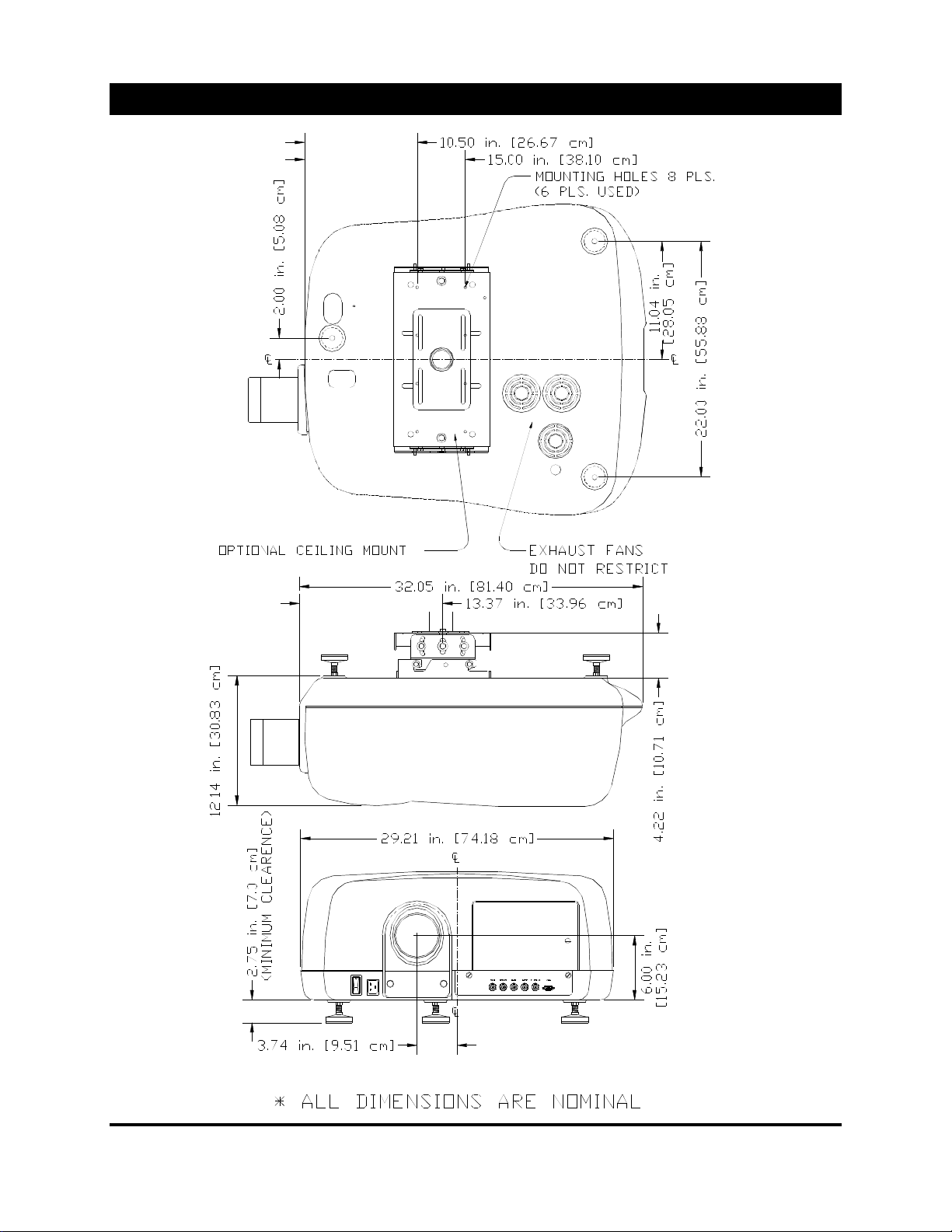
Projector Dimensions
37
5200 User’s Manual
Page 40
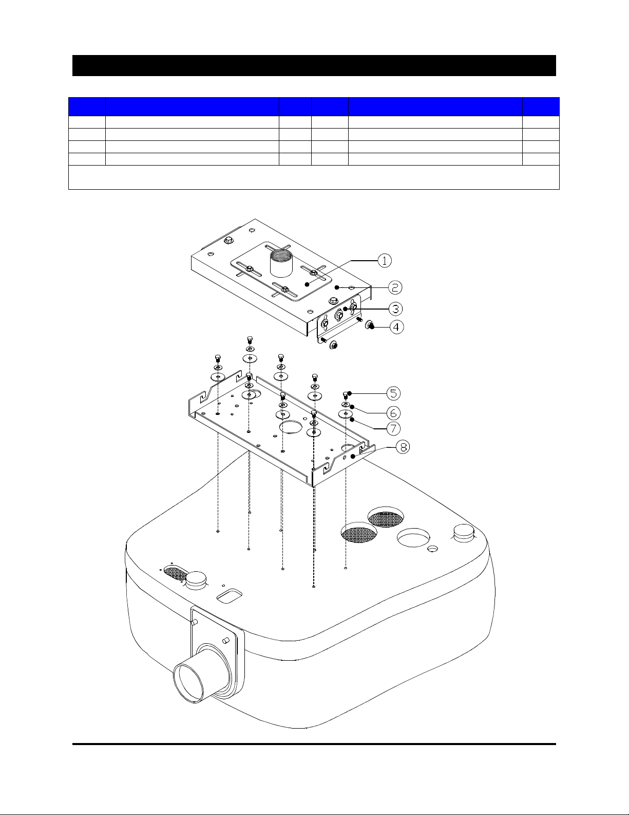
Ceiling Mount Information
Ceiling Mount (69728) P art s Li st
Item Description Qty Item Description Qty
1 Top Slide Bracket w/1-1/2” Pipe Coupler 1* 5 5/16-18 x 5/8” Hex Bolts 6
2 Ceiling Mount Housing 1 6 5/16 I.D. Split Lock Washer 6
3 Mounting Plat es 2 7 5/16 I.D. Fl at W asher 6
4 5/16-18 Flange Nuts 4 8 HB-Hanging Br ac k et 1
* 1 (one) Slide Bracket i ncl uded w/kit. Depending on your parti c ular application, an additional bracket may
be required.
38
5200 User’s Manual
Page 41

Ceiling Mount (69728) Dimensions
Ceiling Mount Information
Top Slide Bracket
Ceiling Mount Housing
39
5200 User’s Manual
HB-Hanging Bracket
Page 42
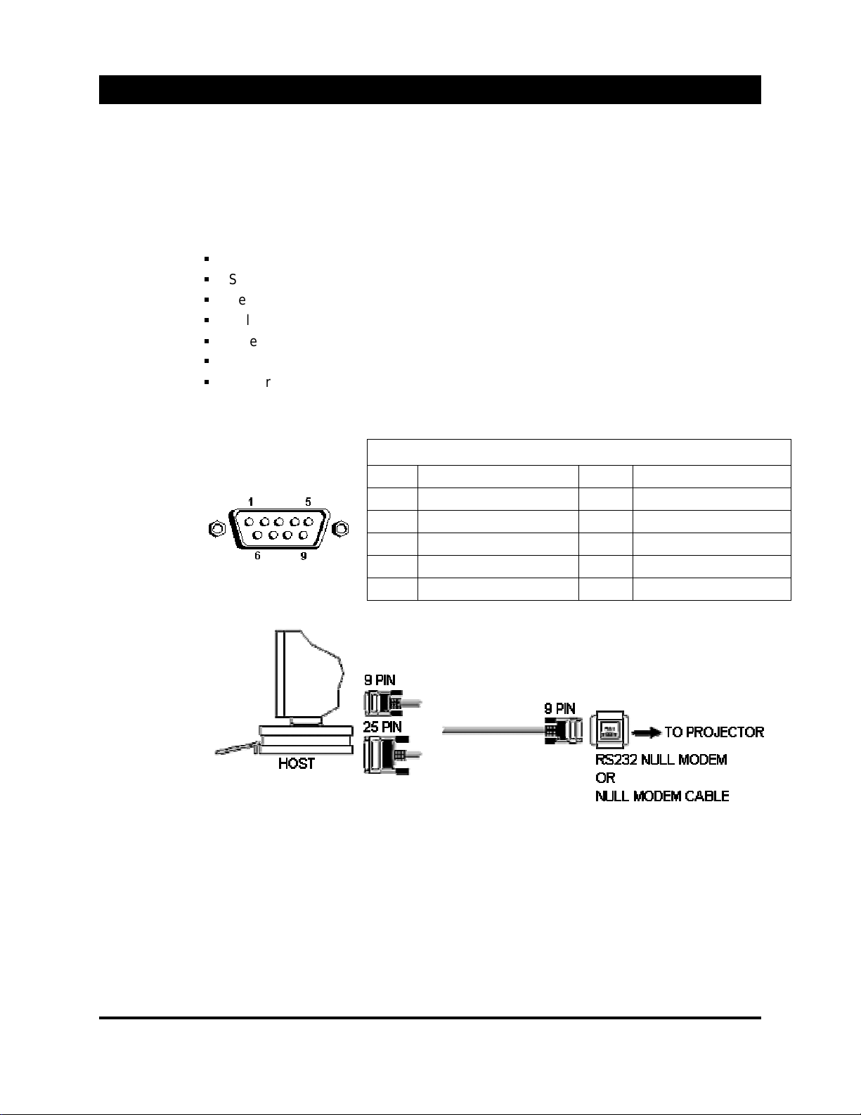
RS-232C Interface Data
An external PC or third party controller may be used to control y our A LICE 5200. This section will
describe how to connect and cont r ol the 5200 DLP projector usi ng exter nal serial communication wit h
characters and numeri c c ommands.
Enabling Com
Ports
As standard, Serial Port 1 (COM1) is unused and may be used for the external control of the
projector. Perform the following to enable ex ternal control and select whic h S eri al P or t t o
use;
Open the Main menu
Select MENU, then
Select UTILITY
Select CONFIGURE, a pop-up selec tion box will open.
Select Exter nal Control Enable, then select the desir ed “ Com Port ” .
Exit the menu system.
Restart the system
Com 1 & 2 Pin Assignments
Pin Numbers Pin Assignments
PIN SIGNAL PIN SIG NAL
1 Data Carrier Detect 6 Dat a S et Ready
2 Serial Input 7 Request T o S end
3 Serial Output 8 Clear To Send
4 Data terminal ready 9 Ring Indicator
5 Signal Ground S hell Chas si s Gr ound
Basic
Connection
Diagram
Protocol
9600 baud, no parity, 8 data bits and 1 stop bit.
40
5200 User’s Manual
Page 43
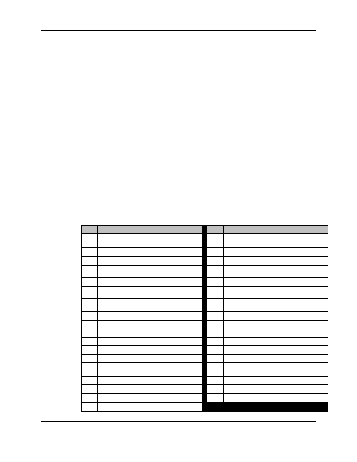
RS-232C Interface Dat a
Character /
Numeric
Commands
Character
Command Table
Commands to the projector ar e two general types. Character c ommands and Numeric
commands. Character commands in fact consist of t wo types. S om e of them put the
projector into a particular adjustment mode. For example, sending a letter B puts the
projector into brightness adjustment mode. Once in that mode, adjustments may be done it
two ways. The character + ( plus) and – (mi nus) respect ively incr ease and decrease the
parameter. Alternatively, a numeric v alue c an be assigned f or the parameter by following the
mode character wit h an integer value, followed by a repeti tion of the mode character. For
example, the comm and B75B would set t he bri ghtness to 75% of maximum.
Other commands carry out a single action such as selecting a channel, deleting a channel,
etc. Some of these comm ands use a prefixed integer parameter, while others use following
integer parameters and/or text strings for channel names. For example, the command 12!
Would select channel 12 and I12 13 NYSC would copy channel 12 to channel 13 and giv e
the name NTSC to channel 13.
All numeric param eters are integers. A decimal point is neither needed nor recogniz ed.
Channel names must consist of upper and/or lower case letters, the digits 0 through 9, the
under bar character “ _” and blank s. Num er ic par am eters are ranged checked. For those
commands that us a percentage value of 0 to 100, values outside those lim its are accepted
and limited to the range of 0 t o 100. For commands that use absolute val ue parameters such
as Phase, values outside t he allowed range are simply r ejected. The acceptable range of
each parameter i s indi c ated in the Character Command Tables.
Any non-digit c har acter such as carriage return, comm a, blank, tab, etc., terminat es a
channel name. For t his reason the command K12 would delete channel 12 but K 12 would
be rejected sinc e a blank (non-numeric character ) following the letter K would terminate the
search for the channel nam e par am eter.
CODE DESCRI PTION CODE DESCRI PTION
Source Select: Use nA where n = 0(RGB1),
A
1(RGB2) , 2(V i d eo), 3(S-Vi d eo), 4( I nt er n al)
B Bright n ess : Us e +/- or BnB , where n = 0 - 100 W Horizontal: Use +/- or WnW, where n = 24 - 527
C Color: Use +/- or CnC, where n = 0 - 100 X Future Use
D Detail: Us e +/- or DnD , w h er e n = 0 - 100 !
E Phase: Use +/- or EnE, where n = 0 - 254 $Help
F Bottom Flagging: Use +/- or FnF, where n = 192
- 2047
G Top Flagging: Use +/- or GnG, where n = 0 -
127
H Tint: Use +/- or HnH, where n = 0 - 100 [Power ON
I Channel Copy From, To, Name (optional) ]Power OFF
J Jitter: Us e +/- or JnJ , where n = 0 - 7 | Future Use
K Channel Delete: Enter Channel Name ^ Auto Search ON
L Ch ann el Find _ Auto Search Off (underscore)
M Channel Save As: Number, Name (optional) { Lock Channel (writ e-protect)
N Pixels: Use +/- or NnN, where n = 64 - 2048,
must be ev en nu m b er
O Power (toggle) # Code Command: n# (see next table)
P Contrast: Use +/- or PnP, where n = 0 - 100 + Increase sel ect ed param et er lev el
Q Channel Lock (toggle) - D ecrease selected parameter level
S Standby (toggle)
V Vertical: Use +/- or VnV, where n = 0 - 1023
Channel Select: !n, where n = desired channel
number
( Standby ON
) Standby OF F
} Unlock Channel
41
5200 User’s Manual
Page 44
RS-232C Interface Dat a
Numeric
Command Table
CODE DESCRIPTION NOTE
101# Bit Sequence: Use 101#n, where n = 0 - 61 1
110# Border Red: Use 110#n, where n = 0 - 255
111# Border Green: Use 111#n, where n = 0 - 255
112# Border Blu e: Use 112#n, where n = 0 -255
113# Black Level Red: Use 113#n , where n = 1 - 254
114# Black Level Green: Use 114#n, where n = 1 - 254
115# Black Level Blue: Use 115#n, where n = 1 - 254
116# Gain Red: Use 116#, where n = 0 - 63
117# Gain Green: Use 117#n, where n = 0 - 63
118# Gain Blue: Use 118#n, where n = 0 - 63
119# Gain Master: Use 119#n, where n = 0 - 63
130# Clamp Back Porch
131# Clamp Sync Tip
132# Field: Us e 132# n, w h er e n = 0 - 3 2
133# Odd/Even: Use 133# n, wh ere n = 0 - 5 3
134# Filter Select: Use 134#n, where n = 0 - 2 4
135# Filter Frequency: Use 135#n, where n = 8 - 40
136# Color Matrix: Use 136#n, where n = 0(disable), 1(enable)
137# Orient ati on: Use 137#n, wh er e n = 0 - 3 5
138# Test Patterns: Use 138#n where n = 0 - 6 6
139# Reset lamp Hours
140# Presentation Mode (toggle)
141# Faroudj a Tint : Use 141#n, where n = 0 - 63
142# Faroudj a D el ay: Use 142# n, w h ere n = 0 - 15
143# Source/Channel Query: Use 143#, response is source text, channel #. 7
NOTES
1
Bit Sequence, parameter values 0 through 30 select sequence number n with “run-once” set to 0. Values 31
through 61 select sequence number n –31 with “run-once” set to 1.
2
Field, parameters 0 through 3 select the 4 possible combinations of the frame drop and filed jam. Selections
are;0 = none1 = frame drop2 = filed jam 3 = frame drop an d fi eld jam
3
Odd/Even, parameter values 0 through 5 select the 6 possible combinations of odd/even sense and even
start line. The selections are;
0 = non-standard w/even start line = odd
1 = standard w/even start line = odd
2 = non-standard w/even start line = odd-1
3 = standard w/even start line = odd-1
4 = non-standard w/even start line = odd+1
5 = standard w/even start line = odd+1
4
Filter Selec t, p aramet er n val u es ar e;0 = none1 = video f i lt er2 = graphic filt er
5
Orient ati on, parameter n val u es ar e;
0 = front/floor
1 = front/ceiling
2 = rear/floor
3 = rear/ceiling
6
Test Pattern; param et er n val ues are;
0 = off1 = flat field
2 = smooth gray
3 = large checkerboard
4 = grid
5 = gray bars
6 = small checkerboard
7
Source/Channel query; this command answer back with the name of the current source and the current
channel nu mber. Sour ce names are RGB - 1, R G B-2, Video, S-V id eo an d Intern al.
42
5200 User’s Manual
Page 45
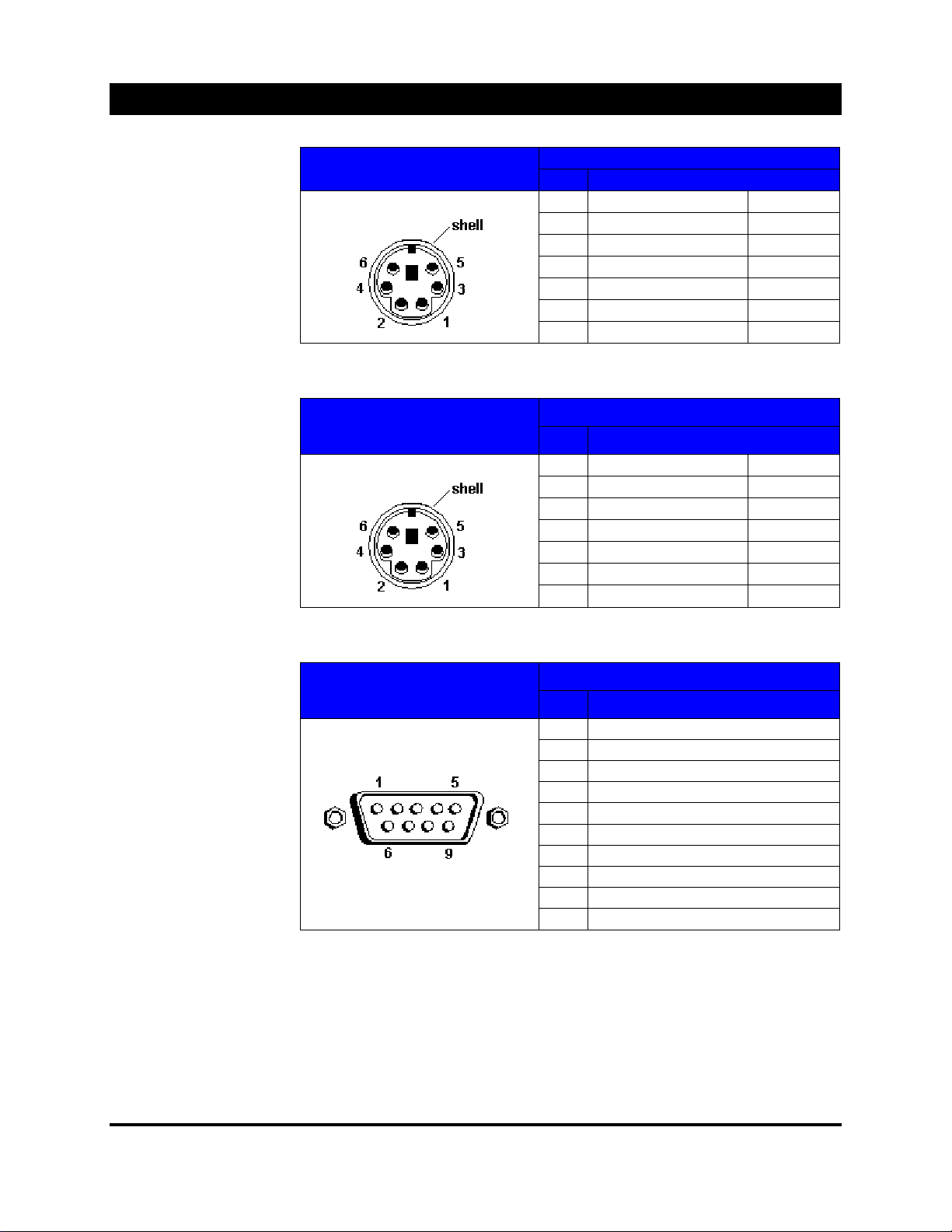
Connector Pin Assignments
Keyboard Port
Your project or comes
standard with a wireless
keyboard. The cables
and adapters for
connecting t he keyboard
IR receiver are prov ided.
P/S 2 Mouse Port
The mouse port is used
to connect the IR
Keyboard Mouse Pad.
Keyboard Port Pin Numbers
Mouse Port Pin Numbers
Keyboard Port Pin Assign ments
Pin Signal
1 Keyboar d Data KBDA TA
2 No Connect ion N/C
3 Signal Ground GND
4 Fused Supply Voltage F V c c
5 Keyboar d Clock KBCLK
6 No Connect ion N/C
Shell Chassis Ground N/A
Mouse Port Pin Assignments
Pin Signal
1 Mouse Data MFDATA
2 No Connect ion N/C
3 Signal Ground GND
4 Fused Supply Voltage F V c c
5 Mouse Cloc k MFCLK
6 No Connect ion N/C
Shell Chassis Ground N/A
Serial Port 1 & 2
(COM 1 & 2)
COM1
: Unused. Use for
third party or exter nal
RS232 control.
COM2
: Used to connect
the IR Remote Control
Receiver.
COM 1 & 2 Pin Numbers
COM 1 & 2 Pin Assignments
Pin Signal
1 Data Car r ier Detect
2 Serial Input
3 Serial Output
4 Data terminal ready
5 Signal Ground
6 Data S et Ready
7 Reque st To Send
8 Cl ear To Send
9 Ring Indicator
Shell Chassis Ground
43
5200 User’s Manual
Page 46
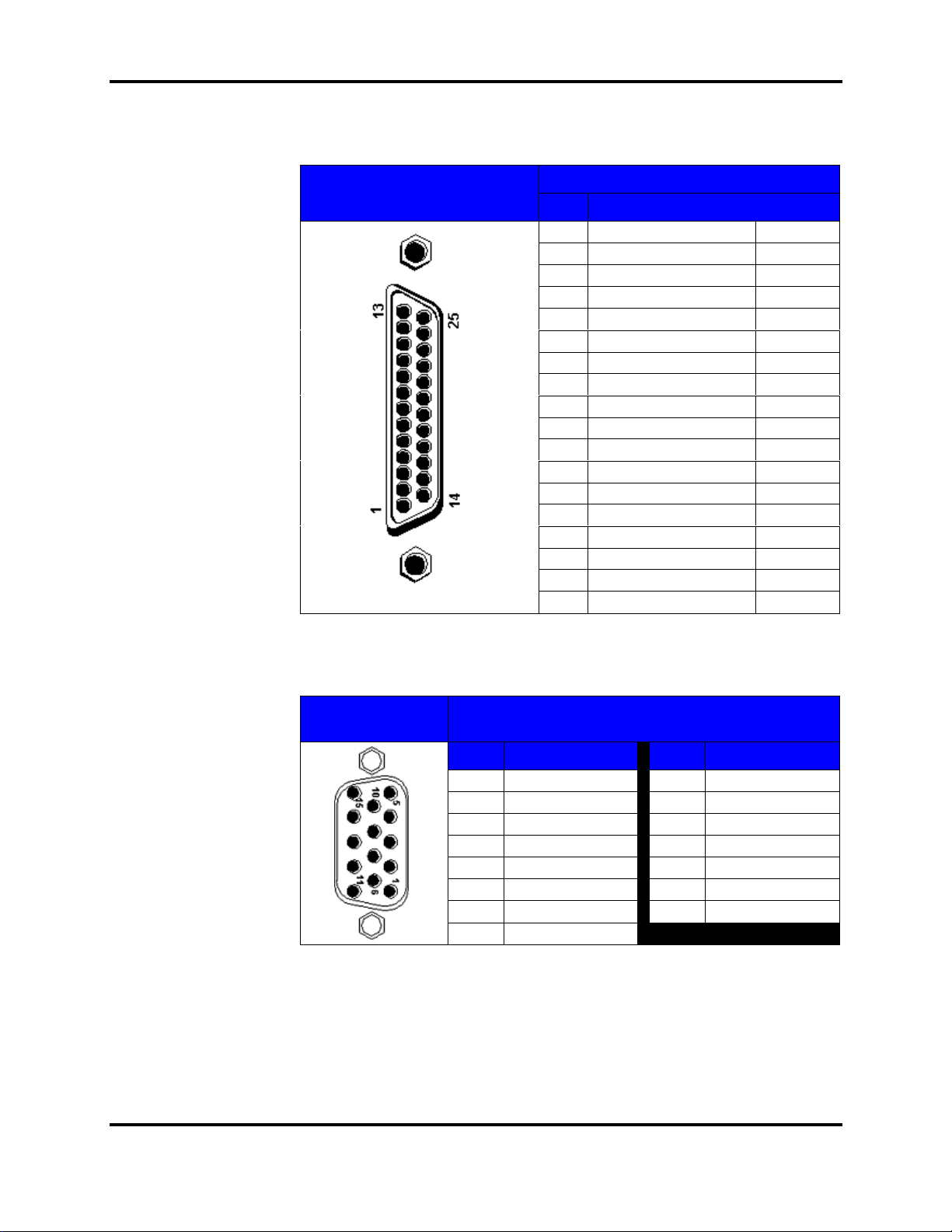
Connector Pin Assignments
Parallel Port (LPT2)
If you reconfigure your
hardware, you may need
the pin numbers and
assignments for the
parallel port connec tor.
The figure below
illustrates the pin
numbers for the parallel
port connector and the
Table (to the right) list
and defines the pin
assignments for the
parallel port connec tor.
LPT2 Pin Numbers
LPT2 Pin Assignments
PIN SIGNAL
1 Strobe STB#
2 Printer Data Bit 0 PD0
3 Printer Data Bit 1 PD1
4 Printer Data Bit 2 PD2
5 Printer Data Bit 3 PD3
6 Printer Data Bit 4 PD4
7 Printer Data Bit 5 PD5
8 Printer Data Bit 6 PD6
9 Printer Data Bit 7 PD7
10 Acknowledge ACK#
11 Busy BUSY
12 Paper End PE
13 Select SLCT
14 Automatic Feed AFD#
15 Error ERR#
16 Initialize Printer INIT#
17 Select In SLIN#
18-25 Signal Ground GND
RGB2 Input
(HD15 pin)
RGB2 Pin
Numbers
RGB2 Pin Assignments
PIN SIGNAL PIN SIGNAL
1 Red Video 9 No Pin
2 Green Video 10 Ground
3 Blue Video 11 ID Bit
4ID Bit 12 ID Bit
5 Self Test 13 Horizontal Sy nc
6 Red Return 14 Vertical Sync
7 Green Return 15 ID Bit
8 Blue Return
44
5200 User’s Manual
Page 47
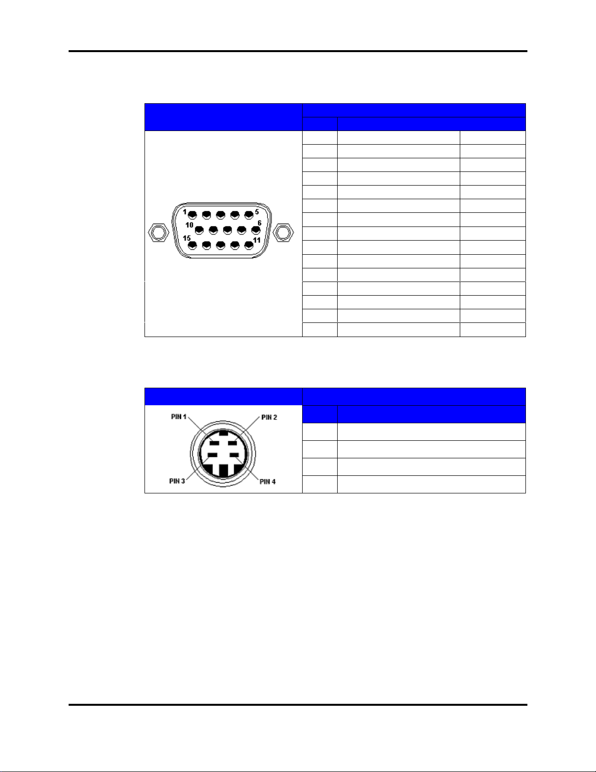
Connector Pin Assignments
Internal Video
Card "OUT"
(HD15 pin)
This port may
be used to
display the
internal SXGA
source to an
external
monitor.
Used primarily
when servicing
the project or.
Pin Numbers
Internal Video Card “OUT” Pin AssignmentsInternal Video Card “OUT”
Pin Signal
1 Red Video RED
2 Green Video GREEN
3 Blue Video BLUE
4 Ground GND
5 DDC Return DCD RET
6 Ground Red GND RED
7 Ground Green GND GRN
8 Ground Blue GND BLU
9 Reserved RESV
10 Ground Sync GND SYNC
11 Ground GND
12 DDC Data DDC DATA
13 Horizontal Sy nc hr oniz ation HSYNC
14 Vertical Synchronization VSYNC
15 DDC Clock DDC CLK
S-Video Input
(4 pin mini D)
S-Video Pin Numbers S-Video Pin As s ignm ents
PIN SIGNA L
1 Ground
2 Ground
3 "Y" (1vp-p)
4 "C" (0.285vp-p)
45
5200 User’s Manual
Page 48
Specifications and Options
5200 Specifications
Brightness
DMD Chip Resolution
Contrast
Horizontal Scan Rate
Vertical Scan Rate
Source Compatibil ity
Computer Features
Pentium Processor 233 MHz with MMX
Hard Drive 4 GB
Memory 64 MB
ISA/PCI Slots 7 Total
Model Fea t ur e s
Physical
Power/Voltage 1200 W / 85-240 VAC (auto-ranging)
Dimensions 11.7" H x 29" W x 32" D (30 cm H x 74 cm W x 82 cm D)
Weight (net) 80 lbs. (37 kg)
IR Keyboard / Mouse & Remote Cont r ol, Wi ndows, CD-ROM , Modem,
Network Interfac e, and Audio Card
2000 (ANSI Lumens)
1024 x 768
250:1 ANSI
15-64 kHz
30-120 Hz
1280 x 1024
Lamp Type
Colors
Color Temperature
Temperature
Operating 50° to 104°F (10° to 40°C)
Storage 32° to 150° F (0° to 65°C)
Noise Level
Remote Control
IR Keyboard/Mouse & Remote Key boar d / mouse & remote control offer c om plete control of projection
functions thr ough the user interface.
RS-232C Codes suppl ied for comput er control or conference room system
controller (mask on-screen menus)
Lens Shift
Certificati on s
Internal Test Patt erns
Specifications s ubjec t to change without prior notice.
± 1/2 total image height from center screen (l ens depended)
Color bars, gray scal e, chec k er boar d, crosshatch, and others
500 Watt Xenon Arc Lamp
16,700,000
3600 °K, 6500 °K, 9200 °K, User
<45 dbA (1 meter)
CE and FCC approved, UL pending
46
5200 User’s Manual
Page 49
Specifications and Options
Options
Lenses
Switcher
Ceiling Mount Kit
Remote Controls
Manual
Input Options
Retro Consoles
Fixed: 1.0: 1, 2. 3:1, 3.9: 1, 5. 5:1
Zoom: 1.2-2.3: 1, 2. 34- 5.5:1, 1.5-2.5:1, 2.5-4.0:1
8-channel, 250Mhz bandwidth, table or rack mount switcher with separate or
composite sync inputs, audio follow, RGsB, Video or S - Vi deo and 5' (152 cm) RS232C cable
Ceiling mount kit with adjustments for roll, pitc h and y aw
Infrared Keyboar d / mouse & rem ote
Service Manual
Faroudja Video/ S - Vi deo dec oder for NTSC and Pal
AmPro Quad Decoder for NTSC, Pal and S E CAM
Options that empower ALICE for cutting edge applications
Available from AmPro or your PC Vendor
Teleconference P ackage Audio Card IR Extension
Theater Controller Modem Wired Keyboard and Mouse
DVD ISDN Modem TV Tuner
Windows NT workstation CD-ROM RF Mouse
Microsoft Offi ce 97 Memory Upgrade/16 MB Scanner
Decryption Capabi li t y Hard Drive Upgrade SCS I Port
Network Card
47
5200 User’s Manual
Page 50
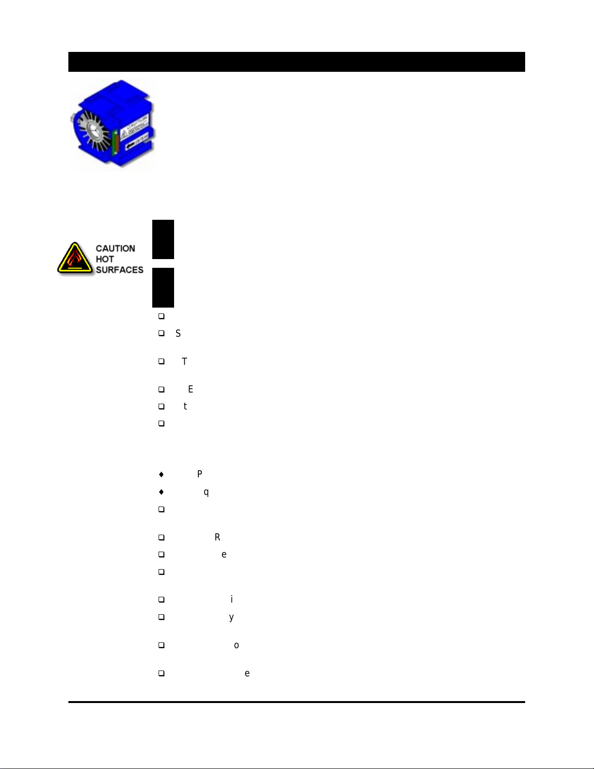
Lamp Module Replacement Procedure
A replacement lamp module m ay be purchas ed ( P /N 69736) from your selling
dealer an authorized AmPro Service Center or AmPro Corporation.
Replacement
Procedures
Adjusting the Lamp
Module
The lamp module is access ed on the rear of t he project or . It consists of a 500W Xenon
lamp mounted in a heat sink and hous ed in a pr otective plastic assembly.
The lamp assembly is very hot during nor m al oper ation. To minimize risk of
potential burns to the skin, allow time for the lamp assem bly to cool to room
!
temperature bef or e s er v ic ing. Be s ur e to handle t he lam p by its plas tic housing only.
The lamp is under great pressur e at all t im es and m ay explode. To reduce the risk
of personnel injury and/or pr oper ty damage, when serv ic ing the projec tor (display
!
engine) wear safety glas s es and allow the lamp to cool completely.
STEP 1. De-energize t he pr ojec tor and remove the ac power cord.
STEP 2. At the rear of the projector, unlock the lamp module access door and lif t the
hinged access door up.
STEP 3. Open the two captive latches securi ng the lamp sub-assembly access door
at the rear of the projector .
STEP 4. Gently, pull the lamp assembly out by its plastic housi ng.
If the lamp is too tight to rem ov e, loosen the t wo lam p adjustment screws.
STEP 5. To install the lam p modul e, slide the lamp assembly in. If the lamp
adjustment screws were loosed, r efer to Adjusti ng the Lamp M odule (below). Close
the inner access door, f asten the two captive latches and close the outer access
door.
Test Pattern: F ull white field or 9-quadrant test patt er n.
Test Equipment: Light Meter (optional).
STEP 1. Adjust the lamp position as need us ing the two adjustment screws. See
Figure next page.
STEP 2. Re-open the outer acc es s door.
STEP 3. Remove the two plugs covering the two adjustment screws.
STEP 4. It is optimal to adjust the light level using a light meter . However , if a light
meter is not available, a vis ual adjus tment will have to do.
STEP 5. Typically the two adjustment screws are set to fully tighten.
STEP 6A. If you are using a light meter , f oc us your att ention on the center of the
image. Adjust the screws for maximum light reading.
STEP 6B. If you are visually s ett ing the light output, adjust unt il the image appears
too be the brightest.
STEP 7. Replace the plugs and c los e the out er access door .
48
5200 User’s Manual
Page 51
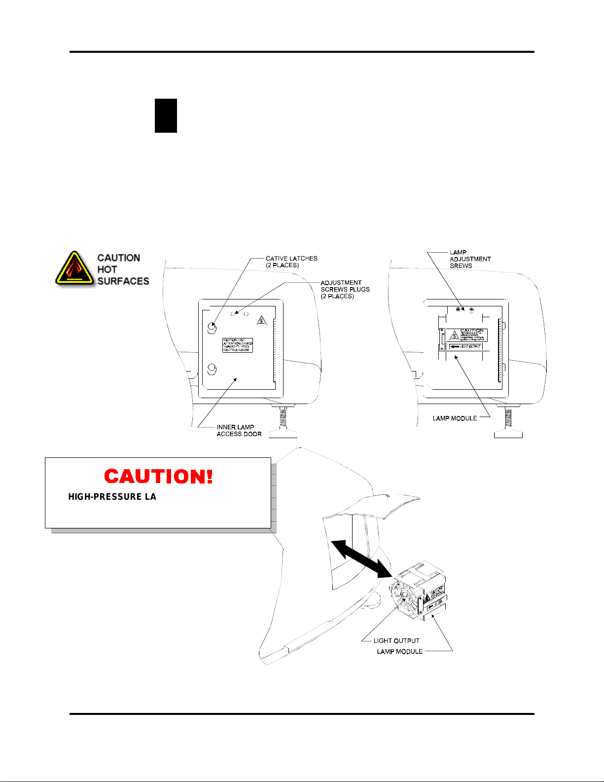
Lamp Module
Disposal
The lamp inside the lamp module is under gr eat pres s ur e. DO NOT incinerate.
Illustrations
WARNING!
injury from metal part ic les .
!
If Desired, pressure can be relieved by any means of breaki ng the copper tubular seal on
the back of the lamp. Pli er s and wire cutt er s work well to break the seal.
Lamps can be discarded as landf ill gar bage. However, the lam p operation timer contains
a small amount of mercury and must be t r eated as hazardous waste if discarded in
volume.
Eye protection should be worn when work ing with the lamp to avoid
Rear View
HIGH-PRESSURE LAMP MAY EXPLODE IF
IMPROPERLY HANDLED. REFER SERVICING TO
QUALIFIED SERVICE PERSONNEL.
49
5200 User’s Manual
Page 52
ALICE Help Guide 1
If your ALICE projector oper ating system is not working as ex pected, and you are not sure of what to do,
start with this guide. This guide directs you through some initial checks and basic tr oubleshooting.
Help Chart
Conventions
Analyzing
Symptoms
Start
Start Symbol – Indic ates
the beginning of a help
map.
Off-Page-Connect or –
Connects parts of a help
map that extends across two
or more pages.
Process Box – Encloses
an action that needs to be
performed.
Document – refers to a
document or procedure
relating to a partic ular point.
Start troubl eshooting by analyzing the symptoms to determine a strategy for resolving the
problem
Consider the foll owing;
Has the system or confi gur ation ever worked? If so, what changed?
Is the error c ondition reproducible or r andom ?
Is the error specif ic to a particular system, configuration, or application?
What particular hardware or firmware i s i nv olv ed?
Are any non-W indows 95 device drivers or TSRs loaded?
Does the order by which drives or applicati on star t-up make a difference?
Does the error sti ll occur with Safe Mode, or Saf e Mode w/Network Support?
For additional informati on r elev ant t o Windows® 95 configuration and operat ion,
please refer to the ref er enc e m aterial included with your system.
Step 1. If desired, connec t an external monitor to the VGA “out ” port
The VGA “out “ port connec tor is located on the PC card cage. Open the f r ont
access door. The VGA “out” por t is in the XXX slot from the right as viewed from the
front, table mounted.
Step 2. Apply main AC to the projec tor and toggle the main AC switch to the “on”
position.
Monitor the boot sequence.
The normal boot-up sequence for the ALICE projector is as f ollows:
The AmPr o 5200 follows an initial “power-up” sequences from the time the main AC
is toggled “on” to the tim e an im age is di spl ay ed.
With the two IR Receivers connected, pl ug the main power cord into the receptacle.
Toggle the main AC switch t o the “on” posi tion. The projector will automatically start,
first displaying the custom Windows boot-up screen, and then the Scan Disk
operation will be ev ok ed.
Once the Scan Disk operation has complet ed, t he pr ojec tor will automatically start
the ALICEXGA program and all associat ed pr ogr ams.
Once all programs have booted, an automati c search for an external source will
start. If an external source is present, the proj ec tor will auto-select or auto-setup t he
source. If no external source is present, the proj ec tor will switch to the internal
graphic channel .
NOTE; if more than one external source is present, t he pr ojector will switch to the
“last source” select ed pr ior to the last shutdown.
50
5200 User’s Manual
Page 53
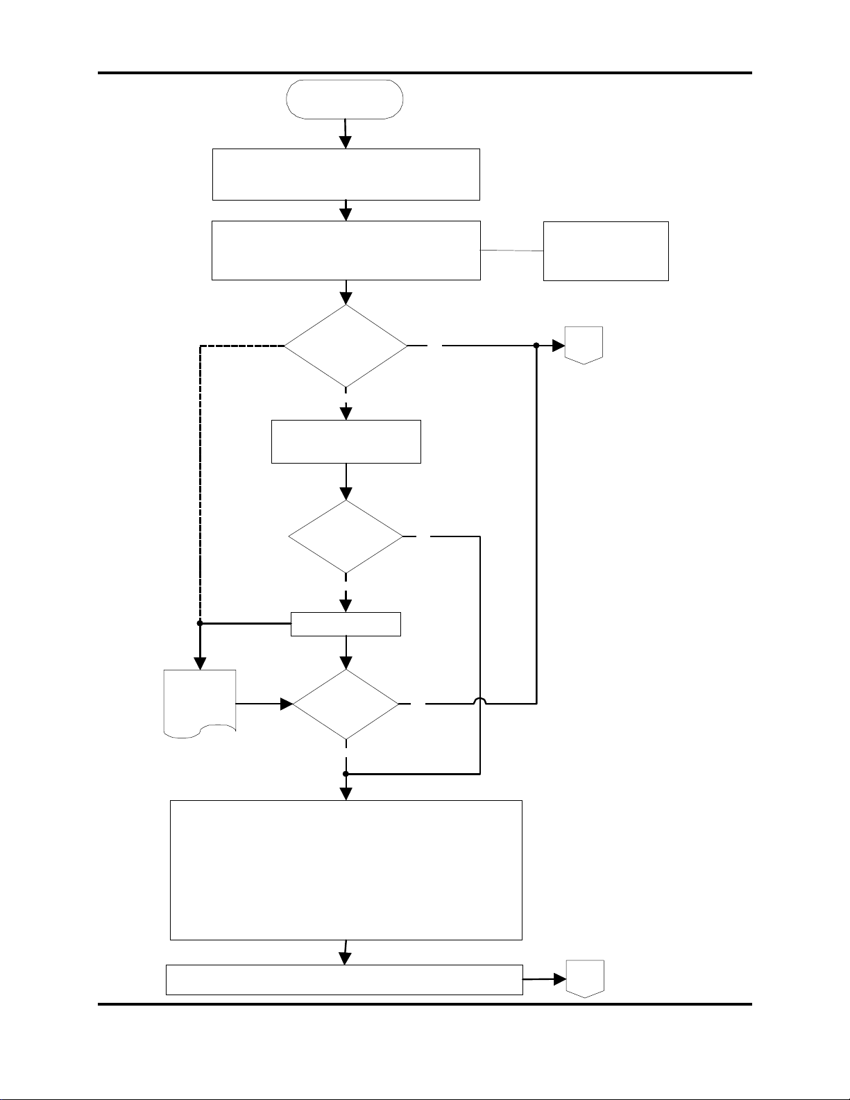
ALICE He lp Guid e 1
Flow
Chart 1
Boot-Up
Problem
Be sure that the IR Keyboard/Mouse and the IR remote
Apply AC power to the projector. Toggle the projector "on".
Mouse are properly connected.
Verify the boot sequence.
Did the
system boot
properly
No
Press DELETE to enter the main
BIOS screen
Yes
If desired, connect an
external monitor to the
projector VGA "out"
connector.
1
Are the
settings
correct?
No
Correct the settings
See
BIOS
Configuration
Procedure
Turn the projector "off" (toggle the main AC switch "off").
Disconnect the main AC power cord from the projector.
Lossen the two captive screws located on either side of the projector towards the
front.
Lift up and lock the top cover in place.
Remove the PC cover-remove the six (6) #6 phillips screws securing the cover in
place.
Check to see if the IDE power, control and data cables are properly connected.
Check system boards and make sure all are well seated in place.
Be Sure that no cable or any other objects are making contact with the CPU fan
Is the
problem
resolved?
No
Yes
Yes
Replace the PC card cage cover, reconnect the system AC and turn the main AC
switch on.
51
5200 User’s Manual
2
Page 54
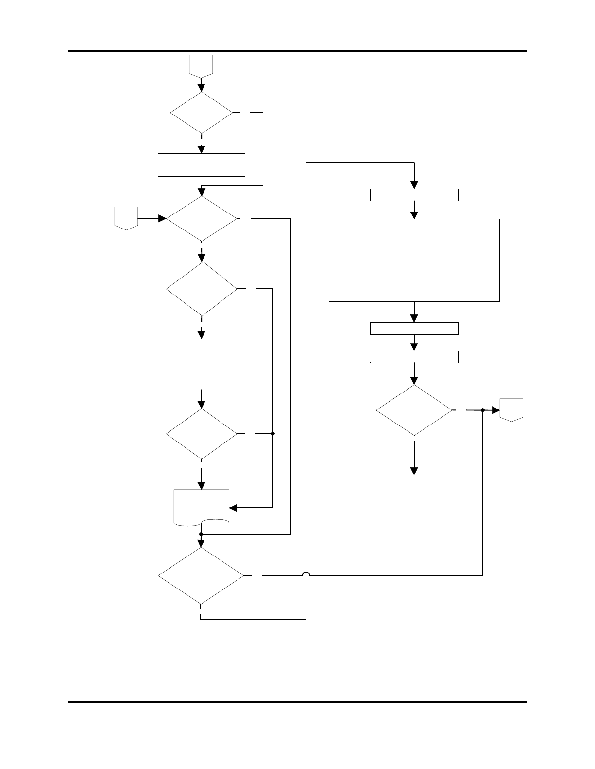
ALICE He lp Guid e 1
Flow
Chart 2
2
Did the
system boot
correct ly
NO
Contact the manufacturer for
additional help.
Does
1
Windows 95 Start
properly
NO
Does it start in
SAFE MODE of
operation
NO
YES
YES
YES
Go to SYSEDIT
Click START then RUN
Type SYSEDIT then click OK
Close autoexec.bat and config.sys windows.
Verify that the following statements are present in your Win.ini
file;
LOAD=C:\MPFX32\MPFX32.EX E
RUN=C:\ALICE\ALICEXGA.EXE
If the above two statements do not appear in the Wi n.ini file,
then enter them at this time.
Re-enter the Data
Re-boot the system and enter the
Windows 95
Safe Mode of operation
(press F8 at the Starting
Windows 95 message.)
Did the
system rest ar t
in Safe Mode
No
See Safe Mode
Operation
Did the
MindPath
and/or the ALICE program
start.
NO
YES
YES
Reboot the system
*
Did the
MindPath
and/or the ALICE
program start.
NO
Contact the manufacturer for
additional help.
YES
*DO NOT HOT BOOT THE SYSTEM
3
52
5200 User’s Manual
Page 55
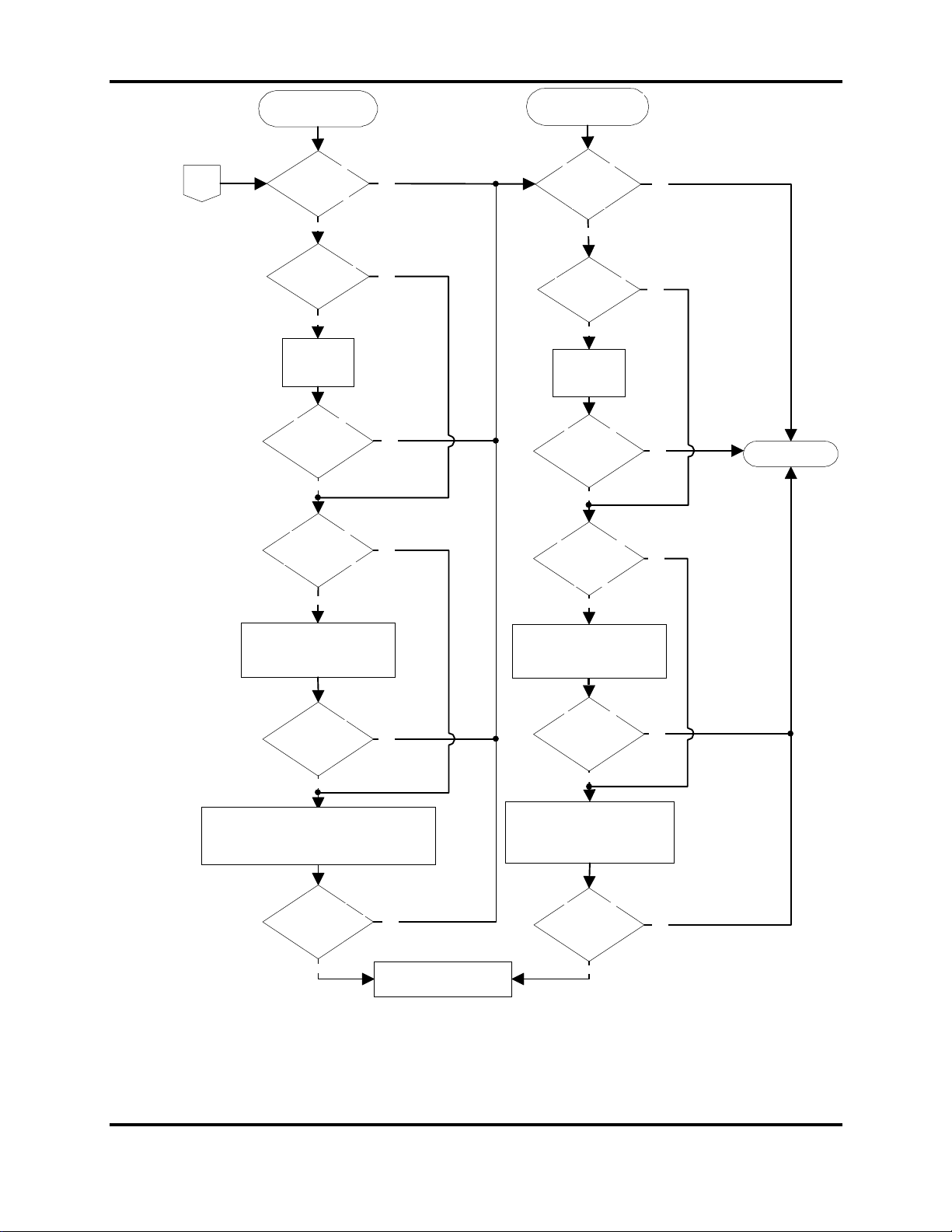
ALICE He lp Guid e 1
Flow
Chart 3
Remote/Mouse
Problem
3
Does the IR
Remote/Mouse
work properly
NO
Are the batteries
good.
NO
Replace the
batteries
Does the IR
Remote/Mouse
work properly
No
Is the Remote
receiver connected
to the correct port
NO
YES
YES
YES
YES
Keyboard/Mouse
Problem
Does the IR
Keyboard and
Mouse work
properly
NO
Are the batteries
good.
NO
Replace the
batteries
Does the IR
Keyboard and
Mouse work
properly
NO
Is the Keyboard
and Mouse
connected
properly
NO
YES
YES
YES
YES
END
Turn the projector "off"
*
Toggle main AC "off"
Disconnect main AC plug.
Connect properly and reboot
Does the IR
Remote/Mouse
work properly
NO
Turn "off" the MindPath program
Copy the FX.pro file from the ALICE folder into the
MPFX32 folder.
Re-start the MindPath program.
Does the IR
Remote/Mouse work
properly now
NO
YES
YES
Contact the manufacturer for
additional help.
Turn the projector "off"
*
Toggle main AC "off"
Disconnect main AC plug.
Connect properly and reboot
Does the IR
Keyboard and
Mouse work
properly
NO
If available, connect another
Keyboard/Mouse and retry.
NOTE: A Standard wired IBM
keyb oard and serial mouse may
be used
Does the IR
Keyboard and
Mouse work
properly
NO
*DO NOT HOT BOOT THE SYSTEM
YES
YES
53
5200 User’s Manual
Page 56
ALICE He lp Guid e 1
BIOS
Configuration
Press <Delete> to ent er the main BIOS screen and c hec k the following parameter s
IDD HDD AUTO DETECTION
Select t he setting that includes LBA mode
Press <Enter> three more times and answer NO to each prompt.
STANDARD CMOS SETUP
Be sure primar y type = user, m ode = LBA, and r epor ted drive size corresponds to
actual drive si z e.
Enter cor r ect date and time
Set HALT ON to NO ERRORS
Set drive A to 1.44M, 3.5 in.
Set VIDEO t o EGA/ VGA
BIOS FEATURES SETUP
Boot sequence is C, A
Boot UP Num Lock is
P/S2 mouse function is
Exit to Main menu
CHIPSET FEATURES SETUP
Auto configur ation is
DRAM timings is 60ns
System cacheable is
Video BIOS cacheable is
Exit to Main menu
POWER MANAGEMENT SETUP
Power Management is
Exit to Main menu
PNP/PCI Configuration
Resources Controlled By is
Exit to Main menu
INTERGRATED PERIPHERALS
IDE HDD Block mode;………….….………..….
IDE PIO for all four ports;………….………..….
On Chip Primary and Secondary P IO ;…… .….
PCI slot IDE 2nd channel;………….………..….
Onboard FDC contr oller ;…… ……. ……….. …..
Onboard UART1;………….………..…………..
Onboard UART2;………….………..…………..
Onboard Parallel P or t; … ……….………. .…….
Parallel Part Mode;………….………..………..
Exit to Main menu
OFF
enabled
enabled
enabled
enabled
disabled
Auto
enabled
enabled
enabled
disabled
enabled
3F8, IRQ4
2F8, IRQ3
378, IRQ7
normal or SPP
Select SAVE & EXIT, then enter “Y” to the resulting dialog box. System will now re-boot.
54
5200 User’s Manual
Page 57

ALICE He lp Guid e 1
Safe Mode
Operation
Windows® 95 will automatically initiate Safe Mode if it detects that the system star t-up has
failed, for exam ple if t he Registry is corrupted, or an applic ation has requested Safe Mode.
Sporadicall y , Wi ndows® 95 will start Safe Mode for no apparent reason. If this is the case,
simply rebooti ng the system will resolve the problem .
To access Windows® 95 Startup Menu, when you see the message “Starting Windows 95 ,”
press F8.
At times, simply pressing “NO RM A L” at t he Star tup Menu will resolve the probl em.
Use Safe Mode for system startup si tuations such as the foll owing
If Windows® 95 fails to start after the “Starting Windows 95” message appears.
If Windows® 95 seems to stall for an extended peri od.
Windows® 95 doesn’t work cor r ec tly or has an unexpect ed r esul t.
If you cannot pri nt to a local printer after att em pting other troubleshooting steps.
If your video display doesn’t work properly . In the case of the ALICE, connect an
external monitor.
If your computer stalls repeatedly.
55
5200 User’s Manual
Page 58

AmPro
Operations
525 John Rodes Boulevard
Melbourne, FL 32934
Phone: 407-254-3000
Toll Free: 800-254-3001
Fax: 407-253-3001
E-mail: sales@a mprocorp. co m or
[email protected]
Corporate Office and Florida
AmPro
420 N. Bernardo Avenue
Mountain View, CA 94043
Phone: 650-962-8281
Fax: 650-962-8295
AmPro
175-G New Boston Street
Woburn, MA 01801
Phone: 781-932-4800
Toll Free: 800-556-7733
Fax: 781-932-8756
AmPro
Glebelands House
Silchester Road
Bramley, Hampshire UK RG26 5DQ
Phone: 44-1256-880777
Fax: 44-1256-881145
E-m ail: sales@ euro pe.amprocorp .com
Light Valve Products
Prosumer Products
Europe
AmPro
2/F D Capital Trade Centre
No. 62 Tsun Yip Street
Kwun Tong Kowloon, HK
Phone: 852-2797-3998
Fax: 852-2797-3213
Pacific Rim
 Loading...