

Page 1
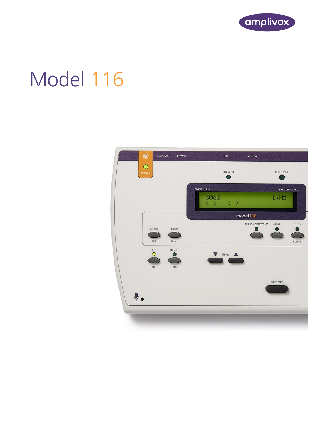
D-0115683-J
INSTRUCTION FOR USE
Page 2

ABOUT THIS MANUAL
1 MODEL 116 INSTRUCTION FOR USE
ABOUT THIS MANUAL
READ THIS OPERATING MANUAL BEFORE ATTEMPTING TO USE THE INSTRUMENT.
This manual is valid for the Model 116 (applies from firmware version 4v47 onwards – please refer to
section 1.3).
This product is manufactured by:
Amplivox Ltd
3800 Parkside, Solihull Parkway,
Birmingham Business Park, Birmingham,
West Midlands,
B37 7YG
www.amplivox.com
For all enquiries please contact us under:
Amplivox Ltd
10393 West 70th Street
Eden Prairie
MN 55344
United States
Tel: 888 941 4208
Fax: 952 903 4100
Amplivox Ltd
3800 Parkside, Solihull Parkway,
Birmingham Business Park, Birmingham,
West Midlands,
B37 7YG
United Kingdom
Tel: +44 (0)1865 880846
Page 3

TABLE OF CONTENTS
2 MODEL 116 INSTRUCTION FOR USE
TABLE OF CONTENTS
ABOUT THIS MANUAL 1
TABLE OF CONTENTS 2
1. INTRODUCTION 4
1.1. THANK YOU 4
1.2. INTENDED APPLICATIONS 4
1.3. UNPACKING 4
1.4. FIRMWARE VERSION 4
1.5. STANDARD CONTENTS 4
1.6. OPTIONAL ACCESSORIES 5
2. IMPORTANT SAFETY INSTRUCTIONS 6
2.1. PRECAUTIONS 6
2.2. ELECTROMAGNETIC COMPATIBILITY (EMC) CONSIDERATIONS 6
2.3. POWER SUPPLY OPTIONS 6
2.4. AUDIOMETER CONNECTIONS 8
2.5. DATA TRANSFER TO A PRINTER 8
2.6. DATA TRANSFER TO A COMPUTER 9
3. USING THE AUDIOMETER 10
3.1. SWITCHING THE AUDIOMETER ON AND OFF 10
3.2. TESTING THE PATIENT RESPONSE SWITCH 10
3.3. AUDIOMETER DISPLAY 10
3.4. AUDIOMETER CONTROLS 10
3.4.1. Multifunction Keys 10
3.4.2. MENU 10
3.4.3. Description of Function of Other Keys 11
3.5. THRESHOLD RETENTION FUNCTION 12
3.5.1. Recording thresholds manually 12
3.5.2. Recording thresholds automatically 12
3.5.3. Reviewing retained thresholds 12
3.6. PRINTING AUDIOGRAMS 12
3.7. DATA TRANSFER TO AUDIBASE OR AMPLISUITE 13
4. SUGGESTED SEQUENCE OF OPERATION AND TEST PROCEDURE 14
4.1. AUDIOMETRY PREPARATION AND AMBIENT CONDITIONS 14
4.2. TEST SYSTEM ARRANGEMENT 14
4.3. HEADSET 14
4.4. PATIENT INSTRUCTIONS 14
4.4.1. Pre-test 15
4.4.2. Familiarisation 15
4.4.3. Test 15
4.4.4. Post-test 15
5. SPECIFICATION 16
5.1. OUTPUT DATA 16
5.2. MAXIMUM HEARING LEVELS PROVIDED AT EACH FREQUENCY 16
5.3. PHYSICAL DATA 16
Page 4

3 MODEL 116 INSTRUCTION FOR USE
5.4. EQUIPMENT CLASSIFICATION 17
6. SYMBOLS 18
7. TECHNICAL INFORMATION 19
8. ROUTINE MAINTENANCE 21
8.1. AUDIOMETER MAINTENANCE 21
8.2. TRANSDUCER MAINTENANCE 21
8.3. MAINS ADAPTER MAINTENANCE 21
8.4. BATTERIES 21
9. INSTRUMENT STORAGE AND TRANSPORTATION 22
10. CALIBRATION AND REPAIR OF THE INSTRUMENT 22
11. GUARANTEE 22
12. ORDERING CONSUMABLES AND ACCESSORIES 23
13. DISPOSAL INFORMATION 24
APPENDIX 1 - EMC GUIDANCE & MANUFACTURER’S DECLARATION 25
APPENDIX 2 - USE WITH NON-MEDICAL ELECTRICAL EQUIPMENT 29
Page 5

INTRODUCTION
4 MODEL 116 INSTRUCTION FOR USE
1. INTRODUCTION
1.1. THANK YOU
Thank you for purchasing an Amplivox audiometer. The Amplivox Model 116 is a manual screening audiometer that will
give many years of reliable service if treated with care.
1.2. INTENDED APPLICATIONS
The Model 116 screening audiometer is designed for use by general practitioners, occupational health staff and child
health professionals and is the ideal instrument for primary care groups, schools and industry. The audiometer is not
intended for use by hearing specialists to determine the full extent and scope of a patient’s hearing deficiency.
The instrument is completely portable, and if required may be specified to operate from integral internal batteries (see
Section 2.3 below). Test results may be printed using the specified printer option or transferred to a PC running the
Amplivox Audibase or ampliSuite applications.
1.3. UNPACKING
Open the shipping carton and carefully remove all the equipment. Check against the delivery note that all the
accessories ordered have been included with your audiometer. If anything is missing, please contact Amplivox Customer
Support (+44 1865 880846; [email protected]). If you have purchased from a distributor you should contact them
directly.
Please retain the shipping carton and packing materials as the audiometer will need calibrating on an annual basis and
should be returned to Amplivox in its original shipping carton.
1.4. FIRMWARE VERSION
This operating manual is for firmware versions 4v47 onwards. To check the version of firmware on your audiometer
press and hold the MENU button followed by the TALKOVER button.
1.5. STANDARD CONTENTS
Model 116 Audiometer Audiometric headset
Carrying case Patient response switch
Mains adapter Audiogram cards
Operating manual & ampliSuite Calibration certificate
Page 6

INTRODUCTION
5 MODEL 116 INSTRUCTION FOR USE
1.6. OPTIONAL ACCESSORIES
Battery power function Additional audiogram cards
Audibase software USB Cable
Printer(s) Printer cable(s)
Audiocups (noise reducing earphone enclosures)
Page 7

IMPORTANT SAFETY INSTRUCTIONS
6 MODEL 116 INSTRUCTION FOR USE
2. IMPORTANT SAFETY INSTRUCTIONS
The Model 116 instrument must be used only by practitioners qualified to perform audiometric
tests. It is intended for use as a screening tool.
2.1. PRECAUTIONS
READ THIS OPERATING MANUAL BEFORE ATTEMPTING TO USE THE INSTRUMENT
To comply with the standards IEC 60601-1 for safety and IEC 60601-1-2 for EMC the audiometer is designed to be used
only with the medically-approved mains adapter supplied, which is specified as part of the equipment. Do not use any
other type of mains adapter with this instrument. Refer to Section 12 for the stock number of the adapter.
The audiometer is for indoor use only and should be used only as described in this manual.
The transducers supplied with the audiometer are specifically calibrated with it; if these transducers are changed
calibration will be required.
Do not immerse the unit in any fluids. See Section 8 of this manual for the proper cleaning procedure for the instrument
and its accessories.
Do not use the instrument in an oxygen-rich environment or in the presence of a flammable anaesthetic mixture or
other flammable agents.
Do not drop or otherwise impact this instrument. If the instrument is dropped or damaged, return it to the manufacturer
for repair and/or calibration. Do not use the instrument if any damage is suspected.
The instrument must be stored and used within the specified temperature, pressure and humidity ranges (see Sections
7 and 9).
Do not attempt to open, modify or service the instrument. Return the instrument to the manufacturer or distributor for
all repair and servicing requirements. Opening the instrument will void the warranty.
2.2. ELECTROMAGNETIC COMPATIBILITY (EMC) CONSIDERATIONS
Medical electrical equipment needs special precautions regarding EMC and needs to be installed and put into service
according to the EMC information provided in Appendix 1. This provides guidance on the electromagnetic environment
in which to operate the instrument.
Portable and mobile radio-frequency (RF) communications equipment can affect medical electrical equipment. The
instrument should not be used adjacent to or stacked with other equipment; if this is necessary the instrument should
be observed to verify normal operation.
2.3. POWER SUPPLY OPTIONS
The audiometer is designed for continuous operation and may be powered either by a mains adapter (which is supplied,
and specified as part of the equipment) or optional internal batteries.
Battery operation
Page 8

IMPORTANT SAFETY INSTRUCTIONS
7 MODEL 116 INSTRUCTION FOR USE
To fit batteries (if configured for this option), remove the battery compartment cover on the base of the audiometer,
fit the 4 x 1.5V ‘C’ batteries supplied (UK only) according to the indications on the battery holder and replace the battery
cover.
Batteries should only be changed outside the patient environment. The operator should not touch
the battery connectors and the patient simultaneously.
Note: If using batteries, the instrument will automatically switch off approximately 90 seconds after the last key was
pressed in order to save battery power. Any test results will be automatically saved.
The display will show “Low Batt” when the battery voltage is low. It is advisable to change the batteries as soon as this
happens. Once the voltage of the batteries is too low to operate the instrument, the message “Replace Battery” will
appear. Note that local regulations are likely to cover disposal of used batteries.
Mains operation
All other connections must be made before connecting the output lead from the adapter into the POWER input socket
on the back of the audiometer. Switch on the mains supply - the indicator on the adapter and the POWER indicator on
the audiometer will both illuminate green, showing that the instrument is ready for use.
The output from mains adapter is fitted with electronic circuit protection. In case of overload the adapter will shut down
and the indicator will be extinguished. When the fault is cleared the adapter will operate as normal.
The input to the mains adapter is protected with a non-replaceable fuse. If this fails the adapter will not operate.
The mains adapter is the mains disconnect device and therefore the audiometer should be positioned such that easy
access to the mains adapter is possible.
If a replacement mains adapter is required, please contact Amplivox or your Amplivox distributor.
Page 9
IMPORTANT SAFETY INSTRUCTIONS
8 MODEL 116 INSTRUCTION FOR USE
2.4. AUDIOMETER CONNECTIONS
All the relevant accessory terminals and connections are labelled to ensure correct identification and connection as
follows:-
Socket Label
Socket Type
Colour
Code
Connected Part
Notes
RIGHT
LEFT
6.3mm jack
6.3mm jack
Red
Blue
Air conduction headset *
PRINTER
RJ12 socket (6-way)
Printer *
See 2.5
USB
USB Connector
Type B
Computer (via USB port)
See 2.6
N/A
6 pin mini DIN
Reserved port; Amplivox
diagnostic use only
See
below
POWER
2.5mm power jack
Mains AC/DC Adapter *
RESPONSE
6.3mm jack
Black
Patient Response Switch *
The relevant part numbers are indicated in Section 12
Note regarding the 6-pin mini DIN connector:
This is a restricted socket for Amplivox use only. No user access is permitted.
For connected parts marked * only connect the accessories supplied with the instrument or supplied
by Amplivox or an Amplivox distributor. These parts have been tested for use with the Model 116
Screening Audiometer for compliance with the standards IEC 60601-1 and IEC 60601-1-2. The use of
accessories other than those specified may compromise compliance with these standards. For other
sockets refer to Appendix 2.
2.5. DATA TRANSFER TO A PRINTER
Please refer to Appendix 2 for important information regarding the connection of non-medical
electrical equipment to medical electrical equipment.
The audiometer can be upgraded with an option to allow connection to one of two designated portable thermal printers
for printing audiometric test results (see Section 3.6). You must use the designated cable for each printer, which is
supplied with this option.
Upon receipt of the printer it must be initially charged for a minimum of 15 hours prior to use.
Page 10

IMPORTANT SAFETY INSTRUCTIONS
9 MODEL 116 INSTRUCTION FOR USE
2.6. DATA TRANSFER TO A COMPUTER
Please refer to Appendix 2 for important information regarding the connection of non-medical
electrical equipment to medical electrical equipment.
The audiometer is supplied with software to allow connection to a computer for the transfer of test results (see Section
3.7). You must use the designated USB cable which is available from Amplivox (see Section 12).
Page 11

USING THE AUDIOMETER
10 MODEL 116 INSTRUCTION FOR USE
3. USING THE AUDIOMETER
3.1. SWITCHING THE AUDIOMETER ON AND OFF
Press and briefly hold the switch marked (located on the back panel). No warm-up time is required. The display will
briefly show the model and the type of headphone currently in use. The display will then be similar to that shown in
Section 3.3.
To switch off, press the switch marked again, or press and hold the MENU key followed by the YES (RIGHT) key and
then release both.
3.2. TESTING THE PATIENT RESPONSE SWITCH
Press the patient response switch and the light labelled RESPONSE (above and to the right of the display) will illuminate
green.
3.3. AUDIOMETER DISPLAY
On start-up the display will show the following default setting:-
SIGNAL dBHL FREQUENCY Hz
30dB 1kHz
< > < >
This indicates that when the PRESENT key is pressed, a tone will be presented at 30dBHL at a frequency of 1kHz (1000Hz)
to the designated ear. On start up the audiometer defaults to the left ear.
3.4. AUDIOMETER CONTROLS
3.4.1. MULTIFUNCTION KEYS
Several keys on the audiometer have different functions depending on the actual mode of operation. These are MENU
(OFF), LEFT (NO), RIGHT (YES) and FREQUENCY (MENU SELECT). The use of these keys is described below.
3.4.2. MENU
Press and hold MENU to access the following options. Use the MENU SELECT keys to step through the available options
and then the NO, YES or SIGNAL keys to select an action or modify a setting. Release of the MENU key then initiates
the action or saves the modified setting and returns to the default display.
Page 12

USING THE AUDIOMETER
11 MODEL 116 INSTRUCTION FOR USE
Menu Option Description
Switch off?: As described in Section 3.1
Clear test?: Press YES and release MENU to clear the Threshold Retention Function results from the
previous test (see also Section 3.5)
Contrast: Adjust contrast using the SIGNAL keys
Store on 2 of 3?: If activated a hearing threshold will be stored automatically when the patient makes a
response to 2 out of 3 tone presents (see Section 3.5.2)
Default level: Adjust the default tone presentation level using the SIGNAL keys
Select printer: Use the SIGNAL keys to select either the Able AP1300 or the Sanibel MPT-II printer
3.4.3. DESCRIPTION OF FUNCTION OF OTHER KEYS
PRINT Press to print the threshold levels displayed (see Section 3.6)
LEFT Press once to select the left ear (the indicator above the key illuminates green); if the left
ear is already selected press again to store the displayed signal value as a threshold (see
Section 3.5.1)
RIGHT Press once to select the right ear (the indicator above the key illuminates green); if the
right ear is already selected press again to store the displayed signal value as a threshold
(see Section 3.5.1)
SIGNAL Press the keys to decrease or increase the level of the tone presented in 5dB steps;
to scroll through the range keep the key pressed
PULSE/CONSTANT Press this key once to enable the pulse tone present function when the PRESENT key is
operated (“Pulse” is displayed); press the key again to enable constant tone presentation
(the indicator above the key illuminates green) and use the PRESENT key to interrupt the
tone; press the key once again to return to default
+20dB This enables tone levels to be presented with up to 20dB higher output; press the key and
then use SIGNAL to access the extra 20dB in 5dB steps; an indicator above the key
illuminates green to show that the function is active Note: this function will not operate
if constant tone presentation has been enabled
WARBLE When selected, the instrument presents a warble tone a green indicator above the key is
used to show that the function is active; this feature may be used in conjunction with the
PULSE/CONSTANT key
FREQUENCY Press the key to select a lower frequency and the key to select a higher frequency
TALK OVER Hold this key to interrupt the test and route the operator’s voice from the front panel
microphone to the headset; the level is adjusted with the SIGNAL keys; when the key
is released the output levels return to their default values
PRESENT Press to present the displayed test signal to the patient. The “PRESENT” indicator above
the display will be illuminated green during tone presentation.
Page 13

USING THE AUDIOMETER
12 MODEL 116 INSTRUCTION FOR USE
3.5. THRESHOLD RETENTION FUNCTION
This function records the thresholds for both ears at each frequency tested. Thresholds may be recorded manually or
automatically.
The operator can then review the results at the end of the test and record them on an audiogram card, print them with
the optional printer (see Section 3.6), or transfer the results to a computer (see Section 3.7).
3.5.1. RECORDING THRESHOLDS MANUALLY
Once a threshold has been determined press the “selected” ear key once again. The threshold will be recorded and
displayed as shown in the illustration in Section 3.5.3. Note: this function will not operate if the “Store on 2 of 3” option
has been enabled (see Section 3.5.2).
3.5.2. RECORDING THRESHOLDS AUTOMATICALLY
If the “Store on 2 of 3” option has been enabled (see Section 3.4.2) then a threshold will be recorded automatically by
the audiometer if the patient makes a response to two out of three manual tone presentations at the same level and
frequency. Thresholds determined using the “Store on 2 of 3” option are displayed within square brackets.
3.5.3. REVIEWING RETAINED THRESHOLDS
To review the retained thresholds, select the required frequency using the FREQUENCY keys. The recorded values
for the left and right ears are shown on the lower line of the display as illustrated below.
SIGNAL dBHL FREQUENCY Hz
30dB 4kHz
20 10
This display shows
thresholds at 4kHz
THRESHOLDS
Left ear 20dBHL
Right ear 10dBHL
To clear the Threshold Retention memory, use the Clear Test menu option described in Section 3.4.2.
3.6. PRINTING AUDIOGRAMS
Two designated thermal printers (the Able AP1300 or the Sanibel MPT-II) are available as options for use with the Model
116 audiometer. The correct printer must be selected (use the MENU options described in Section 3.4.2 to make this
selection).
• Connect the PRINTER socket on the audiometer (6-way RJ12) to the printer with the supplied cable (refer to
Section 2.5 of this operating manual for printer set-up). Note that the printer cables for the Able printer (A108)
and Sanibel (A102) are not compatible.
• Ensure that the printer is fully charged, switched on, loaded with paper and ready to print.
• Press the PRINT key and on the prompt “Is printer ready?” press the YES key. The audiogram will then print. To
cancel press NO.
Page 14

USING THE AUDIOMETER
13 MODEL 116 INSTRUCTION FOR USE
3.7. DATA TRANSFER TO AUDIBASE OR AMPLISUITE
Test results stored within the audiometer may be transferred to the Amplivox Audibase database which is available as
an option and must be installed on to a computer (see Section 12 for the part number). Alternatively, Amplivox
ampliSuite allows data to be transferred to a computer and subsequently viewed, annotated & printed. This software is
supplied on a USB which includes this operating manual.
Refer to the installation & operating instructions provided with Audibase or ampliSuite for further details.
Page 15
SUGGESTED SEQUENCE OF OPERATION AND TEST PROCEDURE
14 MODEL 116 INSTRUCTION FOR USE
4. SUGGESTED SEQUENCE OF OPERATION AND TEST
PROCEDURE
The following applies to air conduction measurements. Refer also to ISO 8253 for guidance.
4.1. AUDIOMETRY PREPARATION AND AMBIENT CONDITIONS
Refer to the appropriate audiometric standards and other relevant publications for guidance on audiometric testing.
Audiometric testing should always be performed in quiet conditions (e.g. a quiet room or an acoustic booth). The
optional Audiocups can provide an additional level of isolation from ambient noise. For further explanation on
permissible ambient noise levels, please refer to the standard ISO6189.
4.2. TEST SYSTEM ARRANGEMENT
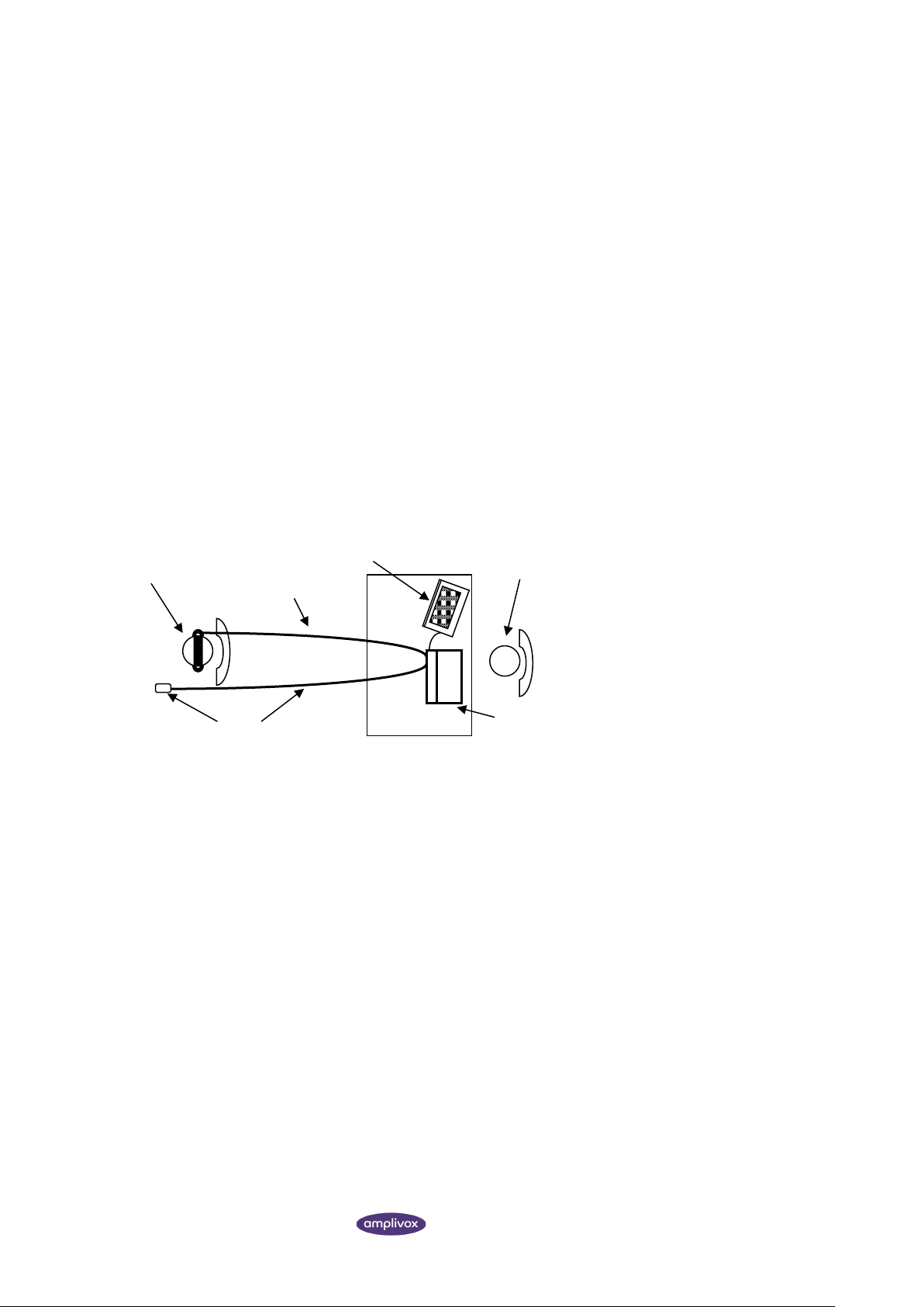
The schematic diagram below shows a typical example of the use of audiometric test equipment. The audiometer is
located on the desk of a seated operator as shown.
The patient is seated in front of the desk facing away from the operator. The patient wears a headset (see Section 4.3)
and responds to test stimuli by use of a hand-held switch which is also connected to the instrument.
4.3. HEADSET
The headset must be fitted by a qualified person to ensure a proper seal and a comfortable fit. The leads from the
headset are connected to the instrument and the headset is then fitted to the patient.
4.4. PATIENT INSTRUCTIONS
The patient should be given the following instructions using the TALKOVER function:
▪ “As soon as you hear the tone, press the response switch. When you no longer hear the tone release the response
switch”
Operator
Audiomete
Computer (optional)
Patient, wearing
Headset lead
Response switch & lead
Page 16

SUGGESTED SEQUENCE OF OPERATION AND TEST PROCEDURE
15 MODEL 116 INSTRUCTION FOR USE
4.4.1. PRE-TEST
(1) Switch the audiometer on
(2) Perform a listening check
(3) Decide whether to use the manual or automatic Threshold Retention Function and/or an audiogram card to
record the thresholds
(4) If the automatic Threshold Retention Function is required ensure that the Store on 2 of 3 option is enabled (see
Section 3.5.2) and that a patient response switch is in use
(5) Prepare the test environment & patient (see Sections 4.1 to 4.4)
(6) If the patient response switch is not being used give instructions to the patient to acknowledge any tone
presented by raising or lowering the finger
(7) Select the better hearing ear (according to the patient) by pressing either the LEFT or RIGHT key and start the
familiarisation session.
4.4.2. FAMILIARISATION
(1) Present the tone 30dB at 1kHz for between 1 and 2 seconds. If there is no response at 30dB, increase the
attenuation level in 10dB steps until the patient responds
(2) When the patient responds, wait for 1 to 2 seconds and present the tone again at the same level; however, if the
patient does respond at 30dB, reduce the signal level in 10dB steps, repeating the presentation until there is no
response, then increase the signal level in 5dB steps until the patient responds; wait 1 to 2 seconds and present
the tone again at the same level
(3) If the responses are consistent with the pattern of tone presentation proceed to Section 4.7 and start measuring
the patient’s hearing thresholds; if not, repeat the familiarisation process
4.4.3. TEST
(1) Present the first test tone at 30dB at 1kHz
(2) If the patient responds, reduce the signal level in 10dB steps repeating the presentation until there is no
response; then increase the signal level in 5dB steps until the patient responds
(3) If the patient does not respond, increase the signal level in 5dB steps until there is a response and then continue
with step 4.
(4) Repeat the test by reducing the signal level in 10dB steps until the patient no longer responds. Then increase the
signal level in 5dB steps until they do respond and note this level.
(5) Repeat step 4 until the patient responds three out of a maximum of five times at the same signal level. This
indicates the patient’s hearing threshold level for that frequency. Either mark the threshold on an audiogram card
or press the appropriate ear key once to activate the Threshold Retention Function and save the threshold level
on screen.
(6) Proceed to the next test frequency. It is common practice to test the frequencies in the following order: 1k, 2k,
3k, 4k, 6k, 8k and 500 Hz.
(7) Repeat steps 1 to 6 for the other ear.
4.4.4. POST-TEST
(1) Use the Threshold Retention Function to review the results (See 3.5)
(2) If required do one or more of the following:
▪ Record the results on an audiogram card, or
▪ Print the results (Section 3.6), or
▪ Transfer the results to a computer (Section 3.7)
Refer to Section 3.4.2 to clear the thresholds at the end of a test and, if required, switch off the audiometer.
Page 17

SPECIFICATION
16 MODEL 116 INSTRUCTION FOR USE
5. SPECIFICATION
5.1. OUTPUT DATA
Outputs: Left and Right earphone
Frequency range: 125Hz to 8kHz
Frequency accuracy: <1%
Distortion: <2%
Output level range: -10dBHL min; see Section 5.2 for maximum
Output level accuracy: Within 3dB
Output level step size: 5dB
Output transducer: DD45 earphones (supplied)
Tone present: Single, warble or pulsed
Communication: Integral talk over facility
USB interface: Transfer of test results to a computer
5.2. MAXIMUM HEARING LEVELS PROVIDED AT EACH FREQUENCY
Frequency,
Hz
Air conduction,
dBHL (DD45)
Frequency,
Hz
Air conduction,
dBHL (DD45)
125
70
2000
100
250
80
3000
100
500
90
4000
100
750
100
6000
100
1000
100
8000
80
1500
100
5.3. PHYSICAL DATA
Display: 2 lines of 24 characters
Battery power (optional): 4x1.5V “C” cells (alkaline recommended)
Mains Power: 100-240Vac; 50-60Hz; 0.5A
Input Rating: 5Vdc; 1.2 A
Dimensions: 270mm long x 165mm deep x 60mm high
Weight (no batteries): 0.75kg (approx)
Page 18

SPECIFICATION
17 MODEL 116 INSTRUCTION FOR USE
Safety: IEC 60601-1 (plus UL, CSA & EN deviations)
EMC: IEC 60601-1-2
CE mark: To the EU Medical Device Regulation
5.4. EQUIPMENT CLASSIFICATION
Type of protection against electric shock Powered via SELV ClassII mains adapter
Degree of protection against electric shock Type B applied part
Degree of protection against ingress of water Not protected
Mode of operation Continuous operation
Equipment mobility Portable
The Model 116 Audiometer is classified as a Class IIa device under Annex IX of the EU Medical Devices Regulation. It is
intended for use as a screening audiometer instrument.
Page 19
SYMBOLS
18 MODEL 116 INSTRUCTION FOR USE
6. SYMBOLS
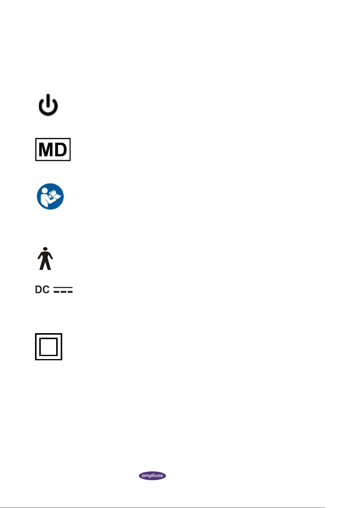
The following symbols appear on the audiometer or mains adapter:
Definition: Identifies the control by means of which the instrument is switched on from (or returned
to) a standby condition.
Definition: Medical device
Definition: Refer to instruction manual (mandatory).
Definition: Type B applied part – an applied part providing protection against electric shock, particularly
regarding allowable patient leakage current and patient auxiliary current.
The applied parts are the left & right earphones, patient response switch and the associated cables.
Definition: The output from the mains AC adapter is Direct Current.
Definition: Class II equipment – equipment in which protection against electric shock does not rely on
basic insulation only, but in which additional safety precautions such as double insulation or reinforced
insulation are provided, there being no provision for protective earthing or reliance upon installation
conditions.
Page 20

TECHNICAL INFORMATION
19 MODEL 116 INSTRUCTION FOR USE
7. TECHNICAL INFORMATION
Audiometer
Audiometer type: Type 4 (IEC 60645-1:2001)
Type 4 (ANSI S3.6:2004)
Battery function
Battery voltage range: 4.0 to 6.0V
Low battery warning: Approx 4.4V
Expected battery life: 6 to 8 hours use from alkaline batteries
Frequency Modulation
Carrier frequencies: 125Hz to 8kHz as per pure tones
Modulation waveform: Sinusoidal
Rising and falling symmetry: Symmetrical on linear frequency scale
Modulating frequency: 15.625Hz
Frequency deviation: +/-10%
Transducers
Types and reference levels: DD45: ISO 389-1, Table 2
Static headband force: Headphones: 4.5N
Sound attenuation characteristics: ISO8253-1, Table 3
Earphone Sound Attenuation Characteristics
Frequency, Hz
125
250
500
1000
2000
4000
8000
Attenuation, dB
2 5 7
15
25
31
23
Environmental
Operating temperature: +15oC to +35oC
Operating humidity: 30% to 90% (non-condensing)
Atmospheric pressure: 700 hPa to 1060 hPa
Page 21

TECHNICAL INFORMATION
20 MODEL 116 INSTRUCTION FOR USE
Input / Output
Power input: 2.5mm barrel-type socket.
Patient response input: 6.3mm Jack socket
Left & Right outputs: 6.3mm Jack socket
USB: Type B socket
Printer: RJ12 socket (6-way)
Maximum voltage at any output: 12V peak
Page 22
ROUTINE MAINTENANCE
21 MODEL 116 INSTRUCTION FOR USE
8. ROUTINE MAINTENANCE
8.1. AUDIOMETER MAINTENANCE
The Model 116 audiometer is a precision instrument. Handle it carefully in order to ensure its continued accuracy and
service. When cleaning the instrument, first disconnect it from the mains supply. Use a soft cloth and mild detergent to
clean the instrument panel when required. Refer to ISO 8253-1 for additional guidance.
8.2. TRANSDUCER MAINTENANCE
Before use check the transducer cables and connectors for signs of wear and/or damage. If you find any, please replace
the item immediately by contacting Amplivox or your Amplivox distributor, requesting the relevant part number (see
Section 12).
Handle the audiometric headset and other accessories with care. For parts that are in direct contact with the patient it
is recommended that replacement parts are used or the parts are subjected to a standard disinfecting procedure
between patients.
This includes physically cleaning and use of a recognised disinfectant. The specific manufacturer's instructions should
be followed for use of this disinfecting agent to provide an appropriate level of cleanliness.
Clean the ear cushions (including those on the Audiocups, if used) with a recognised disinfectant, e.g. a “Mediswab”.
During the cleaning process do not allow moisture to enter the earphone.
8.3. MAINS ADAPTER MAINTENANCE
Before use check the mains AC adapter for signs of wear and/or damage. If you find any replace the adapter immediately
by contacting Amplivox or your Amplivox distributor. Refer to Section 12 for approved part numbers.
DO NOT USE ANY OTHER TYPE OF MAINS ADAPTER WITH THIS INSTRUMENT. See Section 2.3.
8.4. BATTERIES
Batteries (if fitted) should be removed if the instrument is not to be used over an extended period of time.
Page 23

INSTRUMENT STORAGE AND TRANSPORTATION
22 MODEL 116 INSTRUCTION FOR USE
9. INSTRUMENT STORAGE AND TRANSPORTATION
This instrument can be stored or transported within the following environmental parameters:
Temperature: -20oC to +70oC
Humidity: 10% to 90% (non-condensing)
Atmospheric Pressure: 500 hPa to 1060 hPa
10. CALIBRATION AND REPAIR OF THE INSTRUMENT
Amplivox recommends that this audiometer should be calibrated on an annual basis. Please contact Amplivox or the
designated distributor for details of calibration services. Refer to ISO 8253-1 for additional guidance.
The instrument should be returned to the manufacturer for service & repair. There are no userserviceable parts within it.
When packing the instrument for shipping, please use the original shipping carton and packing materials. Please also
ensure that the headset leads are not wrapped around the headband of the headset.
11. GUARANTEE
All Amplivox instruments are guaranteed against faulty materials and manufacture. The instrument will be repaired free
of charge for a period of three years from the date of despatch if returned, carriage paid, to the Amplivox service
department. Return carriage is free of charge for customers in the UK and chargeable for overseas customers.
Important Note:
The following exceptions apply:
Earphones may go out of calibration due to rough handling or impact (dropping). The life of the leads is also dependent
upon conditions of use. These parts are only guaranteed against faulty materials or manufacture.
Page 24

ORDERING CONSUMABLES AND ACCESSORIES
23 MODEL 116 INSTRUCTION FOR USE
12. ORDERING CONSUMABLES AND ACCESSORIES
To order consumables, additional accessories and to replace detachable parts that have been damaged, please contact
Amplivox for current prices and delivery charges. The items available are listed below:
Stock No.
Description
A022
8010855
Audiocups (noise reducing earphone enclosures)
AC1042
8010835
Audiocup ear cushion
AC1047
8507381
Audiocup headband
AC1048
8010834
Audiocup headband cover
A023
8010840
Headband (standard headphone)
A026
8010857
Earphone cushion
A032
8010876
Earphones DD45 *
A030
8010822
Headset lead
B128
8004674
Carrying case
8512734
Approved mains adapter (UE12LCP)
A085
8011155
Patient response switch
A051
8013007
Audiogram cards (pack of 50)
PT02
8029305
Printer Sanibel MPT-II
A102
8004419
Printer cable for audiometer to Sanibel MPT-II
C0104
8029305
Thermal Printer paper for Sanibel MPT-II
F07
8507230
USB Cable, 2.0m
AUD06
8511500
Amplivox Audibase 5.5 (including USB cable)
Accessories marked * require calibration with the specific audiometer to be used. Do not attempt
to use these accessories until the audiometer has been calibrated to match their characteristics.
Shipping documentation will reference the stock number quoted above, and images of the parts alongside the relevant
stock number are available on the Amplivox website (www.amplivox.ltd.uk). The required fitting instructions are
supplied with each part.
Page 25

DISPOSAL INFORMATION
24 MODEL 116 INSTRUCTION FOR USE
13. DISPOSAL INFORMATION
Amplivox Limited is fully compliant with the WEEE (Waste Electrical and Electronic Equipment) Regulations.
Our PRN (Producer Registration Number) is WEE/GA0116XU and we are registered with the approved WEEE
Compliance Scheme, B2B Compliance, approval number WEE/MP3338PT/SCH.
The main purpose of the WEEE Regulations is to encourage the segregation of waste electrical items from the general
waste stream and into reuse, recovery and recycling routes.
For any waste electrical units purchased from Amplivox that either:
• bear the crossed out wheeled bin symbol with black bar underneath
• or, have been replaced with new Amplivox products on a like-for-like basis
please contact our WEEE Compliance Scheme using the details below. B2B Compliance will be able to provide further
information on how to recycle your waste electrical units and answer any queries you may have.
B2B Compliance
Tel: +44 (0) 1691 676 124 (Option 2)
Email: [email protected]
Page 26
APPENDIX 1 - EMC GUIDANCE & MANUFACTURER’S DECLARATION
25 MODEL 116 INSTRUCTION FOR USE
APPENDIX 1 - EMC GUIDANCE & MANUFACTURER’S
DECLARATION
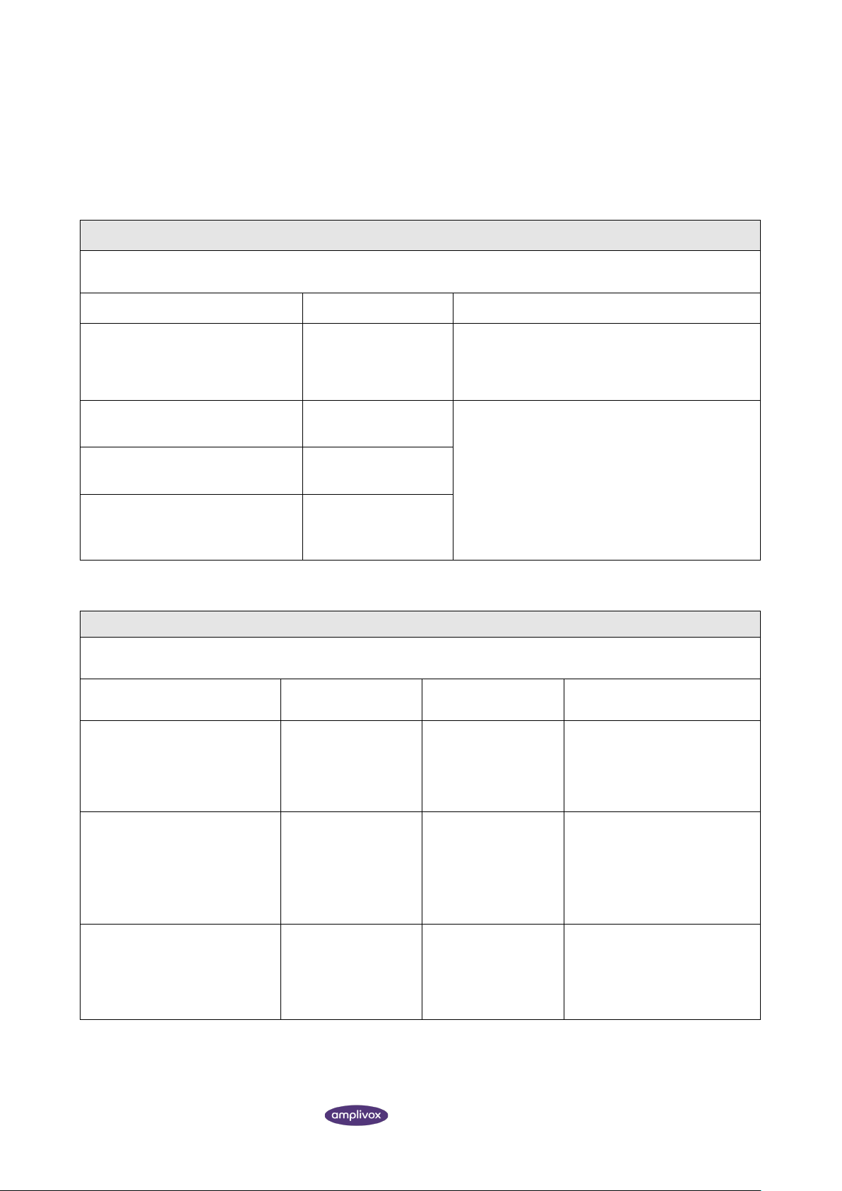
Guidance and manufacturer’s declaration – electromagnetic emissions
The Model 116 Audiometer is intended for use in the electromagnetic environment specified below. The customer or user
of Model 116 Audiometer should assure that it is used in such an environment.
Emissions test
Compliance
Electromagnetic environment – guidance
RF emissions
CISPR 11
Group 1
The Model 116 Audiometer uses RF energy only for its
internal function. Therefore, its RF emissions are very
low and are not likely to cause interference in nearby
electronic equipment.
RF emissions
CISPR 11
Class B
The Model 116 Audiometer is suitable for use in all
establishments, including domestic establishments
and those directly connected to the public low-voltage
power supply network that supplies buildings used for
domestic purposes.
Harmonic emissions
IEC 61000-3-2
Class A
Voltage fluctuations/flicker
emissions
IEC 61000-3-3
Complies
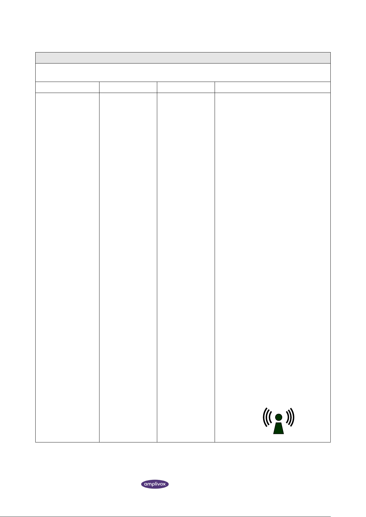
Guidance and manufacturer’s declaration – electromagnetic immunity (1)
The Model 116 Audiometer is intended for use in the electromagnetic environment specified below. The customer or user
of the Model 116 Audiometer should assure that it is used in such an environment.
Immunity test
IEC 60601 test level
Compliance level
Electromagnetic environment –
guidance
Electrostatic Discharge (ESD)
IEC 61000-4-2
±8 kV contact
±15 kV air
±8 kV contact
±15 kV air
Floors should be wood, concrete
or ceramic tile. If floors are
covered with synthetic material,
the relative humidity should be at
least 30%
Electrical fast transient/burst
IEC 61000-4-4
±2 kV for power
supply lines
±1 kV for input/output
lines
±2 kV for power
supply lines
±1 kV for input/output
lines
Mains power quality should be
that of a typical commercial or
hospital environment
Surge
IEC 61000-4-5
±1 kV differential
mode
±2 kV common mode
±1 kV differential
mode
±2 kV common mode
Mains power quality should be
that of a typical commercial or
hospital environment
Page 27

APPENDIX 1 - EMC GUIDANCE & MANUFACTURER’S DECLARATION
26 MODEL 116 INSTRUCTION FOR USE
Immunity test
IEC 60601 test level
Compliance level
Electromagnetic environment –
guidance
Voltage dips, short interruptions
and voltage variations on power
supply input lines (100V/60Hz &
240V/50Hz)
IEC 61000-4-2
0% UT
(100% dip in UT) for 0.5
cycle
0% UT
(100% dip in UT) for 1
cycle
40% UT
(60% dip in UT) for 5
cycles
70% UT
(30% dip in UT) for
500ms
0% UT
(100% dip in UT) for 5
sec
0% UT
100% dip in UT) for 0.5
cycle
0% UT
(100% dip in UT) for 1
cycle
40% UT
(60% dip in UT) for 5
cycles
70% UT
(30% dip in UT) for
500ms
0% UT
(100% dip in UT) for 5
sec
Mains power quality should be
that of a typical commercial or
hospital environment. If the user
of the Model 116 Audiometer
requires continued operation
during power mains
interruptions, it is recommended
that the Model 116 Audiometer
be powered from an
uninterruptible power supply or a
battery
Power frequency (50/60 Hz)
magnetic field
IEC 61000-4-8
30 A/m
30 A/m
Power frequency magnetic fields
should be at levels characteristic
of a typical location in a typical
commercial or hospital
environment.
NOTE UT is the a.c. mains voltage prior to the application of the test level
Page 28
APPENDIX 1 - EMC GUIDANCE & MANUFACTURER’S DECLARATION
27 MODEL 116 INSTRUCTION FOR USE
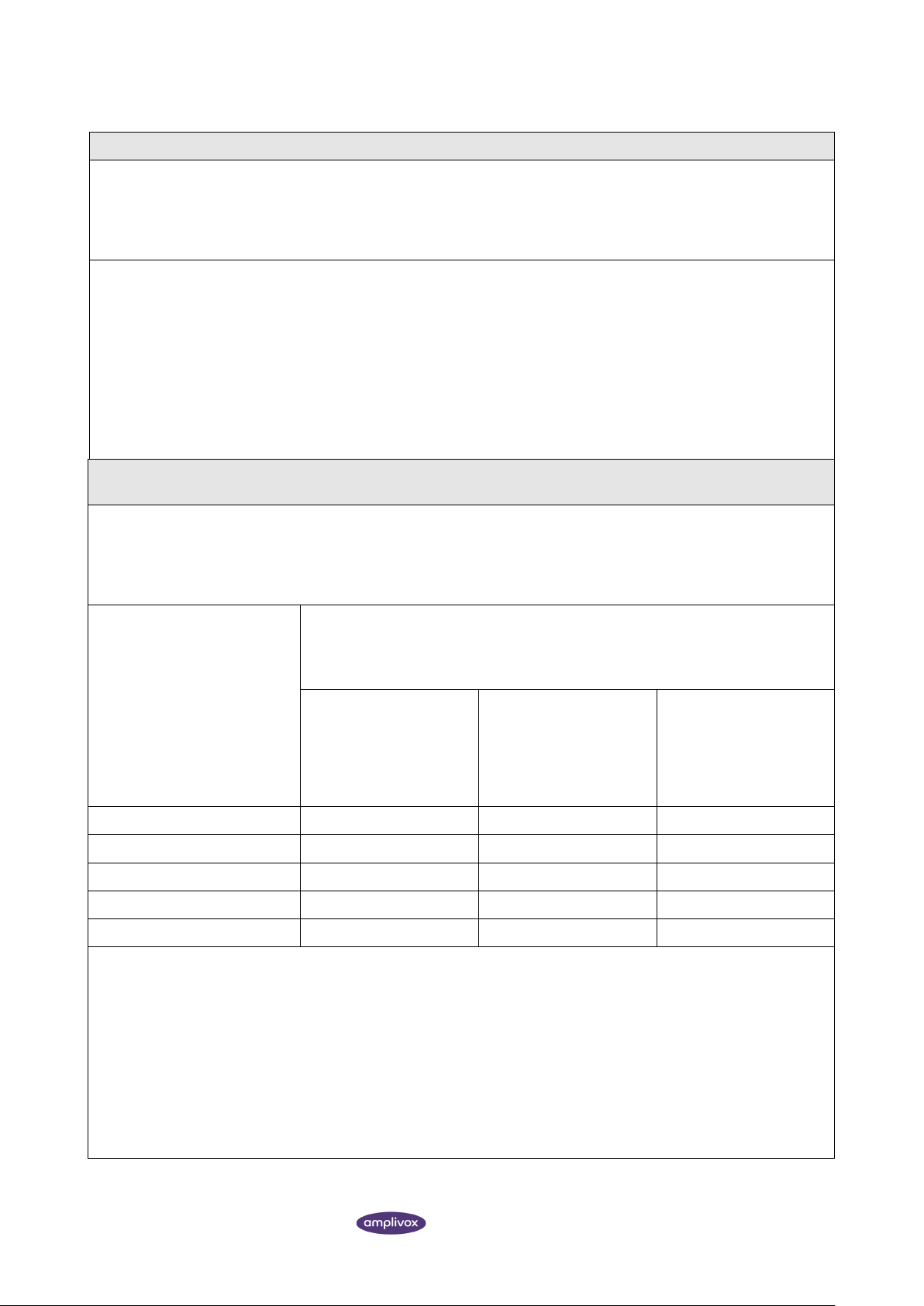
Guidance and manufacturer’s declaration – electromagnetic immunity (2)
The Model 116 Audiometer is intended for use in the electromagnetic environment specified below. The customer or user
of the Model 116 Audiometer should assure that it is used in such an environment.
Immunity test
IEC 60601 test level
Compliance level
Electromagnetic environment – guidance
Conducted RF
IEC 61000-4-6
Radiated RF
IEC 61000-4-3
10 Vrms
150kHz to 80MHz
10 V/m
80MHz to 2.7GHz
10 Vrms
150kHz to 80MHz
10 V/m
80MHz to 2.7GHz
Portable and mobile RF communications
equipment should be used no closer to any
part of the Model 116 Audiometer,
including cables, than the recommended
separation distance calculated from the
equation applicable to the frequency of the
transmitter.
Recommended separation distance
d = 1.2√P
d = 1.2√P 80MHz to 800MHz
d = 2.3√P 800MHz to 2.5GHz
where P is the maximum output power
rating of the transmitter in Watts (W)
according to the transmitter manufacturer
and d is the recommended separation
distance in metres (m).
Field strengths from fixed RF transmitters,
as determined by an electromagnetic site
survey, a should be less than the compliance
level in each frequency range. b
Interference may occur in the vicinity of
equipment marked with the following
symbol:
Page 29
APPENDIX 1 - EMC GUIDANCE & MANUFACTURER’S DECLARATION
28 MODEL 116 INSTRUCTION FOR USE
Guidance and manufacturer’s declaration – electromagnetic immunity (2)
NOTE 1 At 80MHz and 800MHz, the higher frequency range applies.
NOTE 2 These guidelines may not apply in all situations. Electromagnetic propagation is affected by absorption and
reflection from structures, objects and people.
a Field strengths from fixed transmitters, such as base stations for radio (cellular/cordless) telephones and
land mobile radios, amateur radio, AM and FM radio broadcast and TV broadcast cannot be predicted
theoretically with accuracy. To assess the electromagnetic environment due to fixed RF transmitters, an
electromagnetic site survey should be considered. If the measured field strength in the location in which
the Model 116 Audiometer is used exceeds the applicable RF compliance level above, the Model 116
Audiometer should be observed to verify normal operation. If abnormal performance is observed, additional
measures may be necessary, such as re-orienting or relocating the Model 116 Audiometer.
b Over the frequency range 150 kHz to 80 MHz, field strengths should be less than 3 V/m.
Recommended separation distances between portable and mobile RF communications equipment and the Model 116
Audiometer
The Model 116 Audiometer is intended for use in an electromagnetic environment in which radiated RF disturbances are
controlled. The customer or the user of the Model 116 Audiometer can help prevent electromagnetic interference by
maintaining a minimum distance between portable and mobile RF communications equipment (transmitters) and the
Model 116 Audiometer as recommended below, according to the maximum output power of the communications
equipment.
Rated maximum output
power of transmitter
W
Separation distance according to frequency of transmitter
m
150 kHz to 80 MHz
d = 1.2√P
80 MHz to 800 MHz
d = 1.2√P
800 MHz to 2.5 GHz
d = 2.3√P
0.01
0.12
0.12
0.23
0.1
0.38
0.38
0.73 1 1.2
1.2
2.3
10
3.8
3.8
7.3
100
12
12
23
For transmitters rated at a maximum output power not listed above, the recommended separation distance d in
metres (m) can be estimated using the equation applicable to the frequency of the transmitter, where P is the
maximum output power rating of the transmitter in Watts (W) according to the transmitter manufacturer.
NOTE 1 At 80MHz and 800MHz, the separation distance for the higher frequency range applies.
NOTE 2 These guidelines may not apply in all situations. Electromagnetic propagation is affected by absorption and
reflection from structures, objects and people.
NOTE 3 WARNING: Portable RF communications equipment (including peripherals such as antenna cables and
external antennas) should be used no closer than 30cm (12 inches) to any part of the Model 116 audiometer including
cables specified by the manufacturer. Otherwise degradation of the performance of this equipment could result.
Page 30
APPENDIX 2 - USE WITH NON-MEDICAL ELECTRICAL EQUIPMENT
29 MODEL 116 INSTRUCTION FOR USE
APPENDIX 2 - USE WITH NON-MEDICAL ELECTRICAL
EQUIPMENT
Any person who connects external equipment to signal input, signal output or other connectors has created a medical
electrical system and is therefore responsible for the system complying with the requirements of clause 16 of IEC 606011:2005 (General requirements for basic safety and essential performance).
If connections are made to standard equipment such as printers and computers, special precautions must be taken in
order to maintain medical safety. The following notes are provided for guidance in making such connections to ensure
that the general requirements of clause 16 of IEC 60601-1:2005 are met.
The following signal inputs and outputs on the Model 116 audiometer are electrically isolated to the requirements of
IEC 60601-1 in order to reduce any potential hazard associated with the use of mains-powered equipment connected
to these inputs and outputs:
Socket Label
Socket Type
Typical Connection
PRINTER
RJ12 socket
(6-way)
Printer
USB
USB Connector
Type B
Computer
External equipment intended for connection to signal input, signal output or other connectors, shall comply with the
relevant IEC or international standards (e.g. IEC 60950, CISPR 22 & CISPR 24 for IT equipment, and the IEC 60601 series
for medical electrical equipment).
Equipment not complying with IEC 60601 shall be kept outside the patient environment, as defined in IEC 606011:2005 (at least 1.5m from the patient).
The operator must not touch the connected equipment and the patient at the same time as this would result in an
unacceptable hazard.
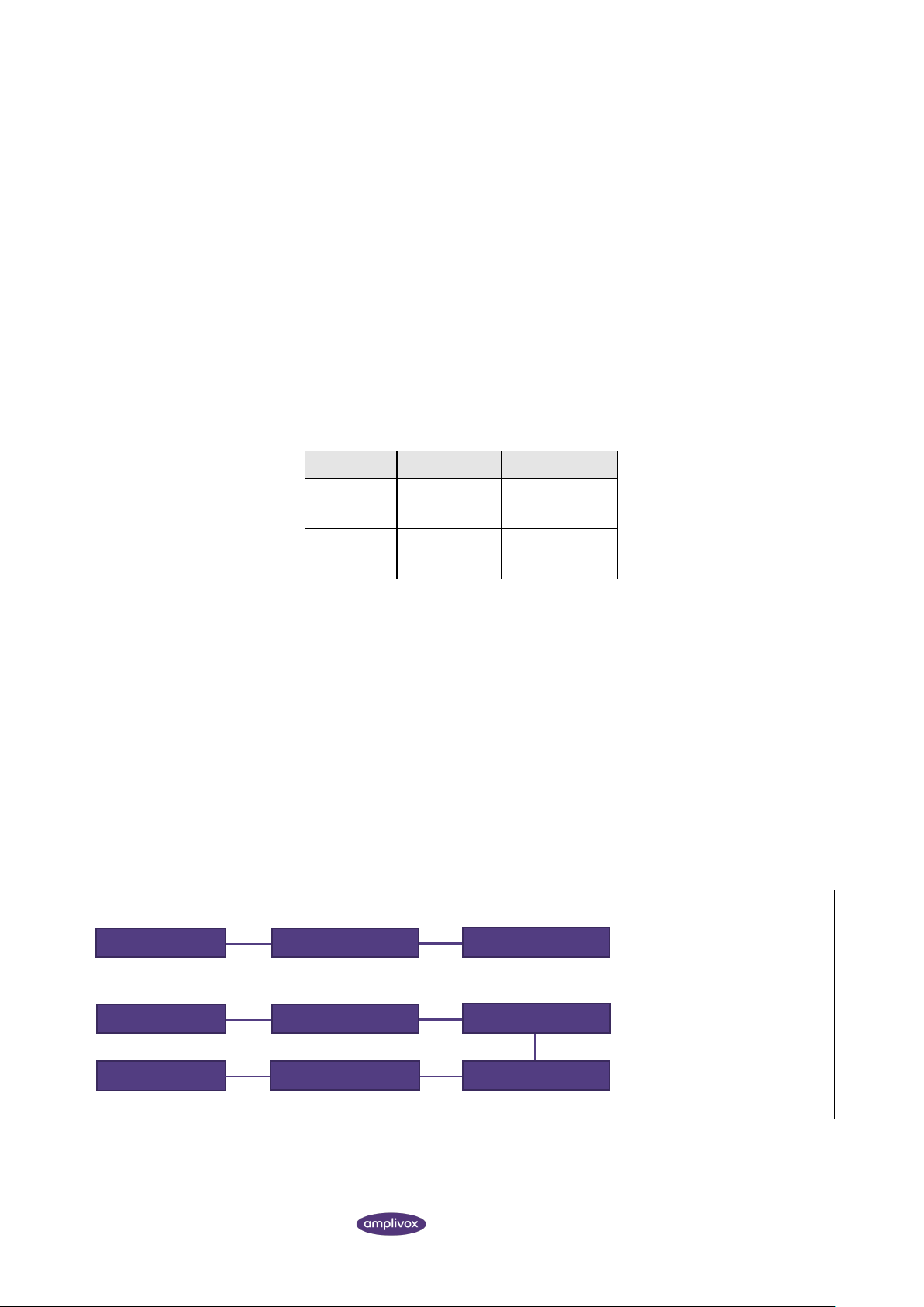
Refer to Diagrams 1 to 3 below for typical configurations of connected peripheral equipment. Refer to Amplivox
Limited at the address given on the front of this user manual if advice is required regarding the use of peripheral
equipment.
Diagram 1: Model 116 used with the medically-approved mains adapter
Diagram 2: Model 116 used with the medically-approved mains adapter and printer
Mains outlet
Medical Mains Adapter
Model 116
Mains outlet
Medical Mains Adapter
Model 116
Printer
Mains outlet
Via cable
Adapter printer
Page 31

APPENDIX 2 - USE WITH NON-MEDICAL ELECTRICAL EQUIPMENT
30 MODEL 116 INSTRUCTION FOR USE
Diagram 3: Model 116 used with the medically-approved mains adapter and PC
Via USB
Mains outlet
Medical Mains Adapter
Model 116
Mains outlet PC
PC
Adapter PC
Page 32

D-0115683-J
Copyright © 2021 Amplivox Ltd
All rights reserved. No part of this publication may be reproduced or transmitted in any form or by any means without
the prior written permission of Amplivox Ltd.
 Loading...