

Page 1

Owner’s manual
R-C652N
6.5” 2-Way Component System
retrosoundusa.com
Version 1.0
October 2012
Page 2

1.
Page 3
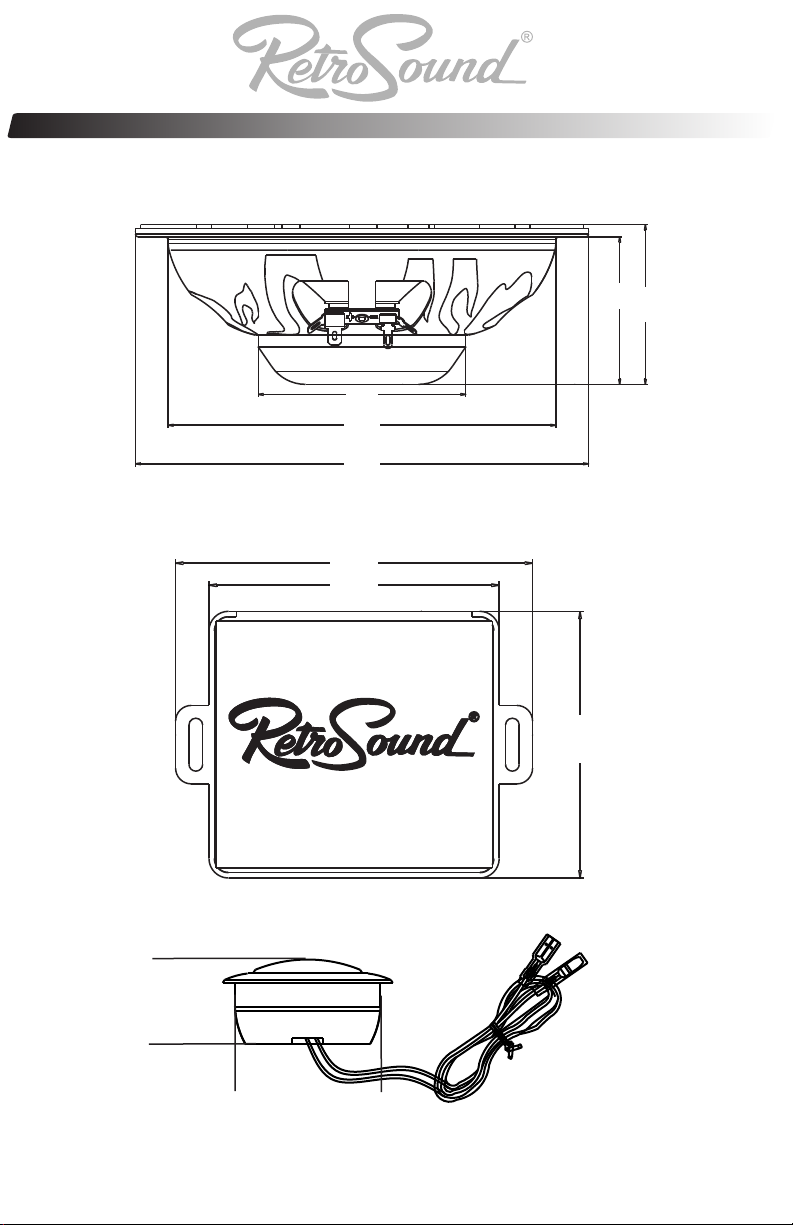
Installation: What’s in the box
Included items:
54 mm / 2.12”
76 mm / 2.99”
144 mm / 5.66”
165 mm / 6.49”
Qty: 2 6.5” midbass drivers w/ wire mesh grilles
91 mm / 3.58”
74 mm / 2.91”
58 mm / 2.28”
74 mm / 2.67”
Qty: 2 2-Way crossover module
26.8 mm / 1.05”
46 mm / 1.81”
Qty: 2 Tweeter w/ surface & flush mount kit
2.
Page 4

Installation: Getting Started
GETTING STARTED
• Turn off the audio system. It is also advisable to disconnect the
negative (–) terminal of your vehicle’s battery whenever
performing installation work.
• Before cutting, drilling or inserting any screw, check clearances
on both sides of the planned mounting surface. Also check for any
potential obstacles, such as window tracks and motors,
wiring harnesses, etc. Check both sides of the vehicle, many
vehicles are not symmetrical.
CROSSOVER NETWORK INSTALLATION
The crossover networks supplied with your RS-C652N
system are water resistant and can be installed inside doors, and
other areas that may be susceptible to the elements. Before
completing the install, please take all precautions to make sure that
your connections are also water resistant and you have used a
silicone based caulk or sealant to make sure your crossover is as
resistant to the elements as possible. The
crossovers can be screwed into a solid surface via the included
mounting points.
Make sure that your mounting location will not cause damage to
wiring, fuel lines, brake lines or any other vital component of your
vehicle.
TWEETER PROTECTION
The RS-C652N crossover networks are equipped with an advanced
electronic tweeter protection circuit designed to minimize the
possibility of tweeter failure. This electronic device monitors current
going to the tweeter and will disconnect the tweeter from the signal
when it senses overload. Should this occur while listening to the
audio system, simply reduce the volume for a few seconds and the
protection circuit will reset itself automatically.
CROSSOVER NETWORK ADJUSTMENT
The crossover networks have been designed to
allow tonal adjustments for tweeter levels in 0, - 3db, and -6dB
increments. These adjustments made via the wiring connections,
make it possible to fine-tune your system to suit your listening
preferences and to compensate for various speaker mounting
applications.
3.
Page 5
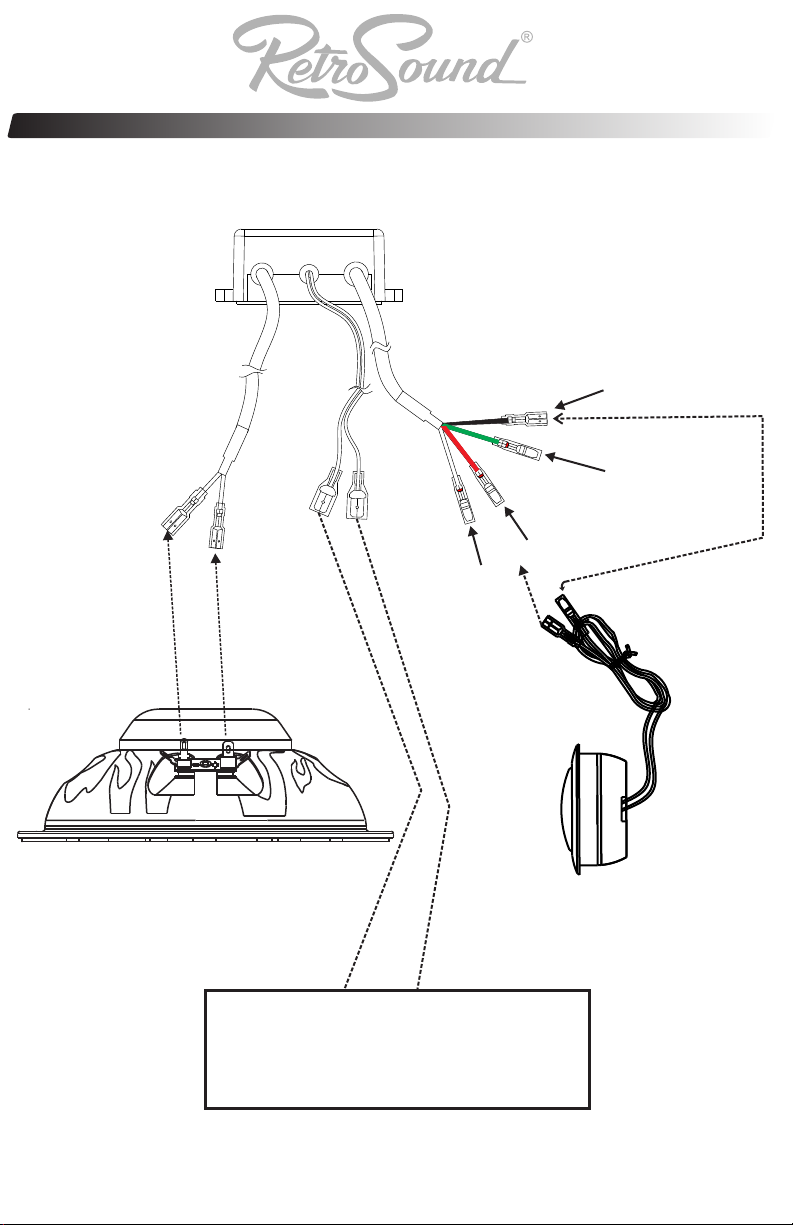
Installation: Wiring Connections
2-Way crossover module
To
From
Amp
To
Tweeter
Midbass
to (+) connector of tweeter
White Wire (-3 dB)
to (+) connector of tweeter
Black Wire
to (-) connector of tweeter
Green Wire (-6dB)
to (+) connector of tweeter
Red Wire (0dB)
6.5” midbass driver
Amplifier / Radio
High Frequency Tweeter
+
-
4.
Page 6

Installation: Speaker Placement
SPEAKER PLACEMENT CONSIDERATIONS
A component system gives you the ability to place the mid
woofer and tweeter separately in your vehicle interior. This can be
good or bad, depending on how it’s done. As a general rule, the
tweeters should be placed relatively close to the woofers for best
tonal balance and most coherent imaging (the closer, the better). Any
separation greater than 8 inches (20 cm)is likely to result in
degraded sound quality. Avoid placing tweeters where they will be
blocked by objects in the interior of the car (including seated
occupants). When selecting a mounting location, look at both sides
of the car to make sure that this location is clear on both sides.
You can always experiment with tweeter placement before
committing to a final mounting location. Simply connect the rest of
the system and allow plenty of wire length for the tweeters. Using
Velcro® or similar material, attach the tweeters in different locations
until you find the one where they perform best.
Woofers will usually be placed into factory speaker locations. If you
have some woofer mounting flexibility, keep the following in mind:
Lower mounting locations, such as the lower front corner
of a door or a kick-panel provide the greatest path length distances
for the sound emitted by the woofer. For this reason, they are
generally more desirable than higher mounting locations. Higher
mounting locations often result in extreme soundstage bias which
compromises the stereo listening experience.
Example of optimum speaker placement
5.
Page 7
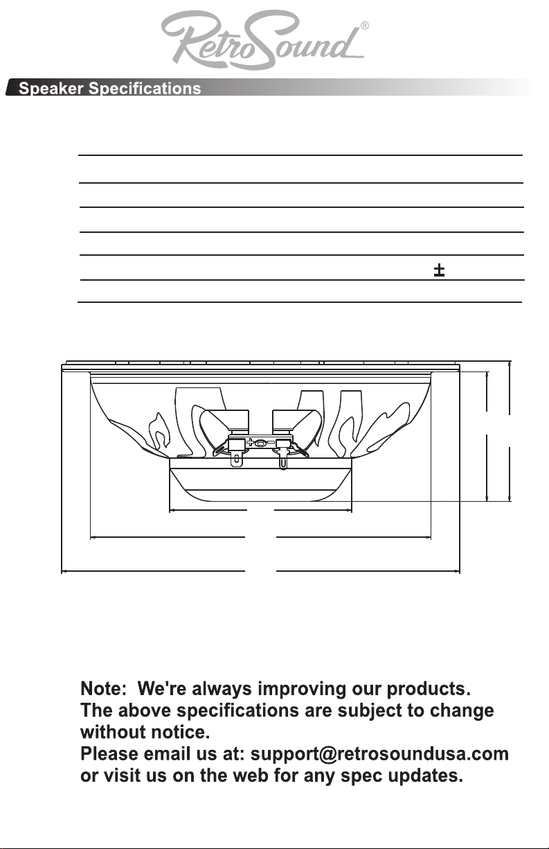
Specifications R-C652N
Nominal Size 6.5” (165.10 mm)
RMS Power Handling 85 watts
Peak Power Handling 150 watts
Nominal impedance 4 ohms
Frequency Response 52Hz-21kHz ( 3dB)
Sensitivity 89 dB (1watt @ 1 meter)
54 mm / 2.12”
76 mm / 2.99”
58 mm / 2.28”
144 mm / 5.66”
165 mm / 6.49”
6.
Page 8

CATEGORIES PARTS LABOR
Radios One (1) Year One (1) Year
Speakers One (1) Year One (1) Year
Accessories (Remotes, cables, etc) 90 Days 90 Days
7.
Page 9

Owner’s manual
R-C652N
6.5” 2-Way Component System
retrosoundusa.com
Version 1.0
October 2012
 Loading...