

Page 1
Global LCD Panel Exchange Center
קᗼۄַؑᄅնሁԫ88ᇆ2ᑔ(ֱࣟઝᖂႼDར
SPECIFICATIONS FOR
CUSTOMER
www.panelook.com
LCD MODULE
CUSTOMER PART NO.
AMPIRE PART NO.
AM-1024768ETMCW-00
APPROVED BY
DATE
Approved For Specifications
Approved For Specifications & Sample
AMPIRE CO., LTD.
2F., No.88, Sec. 1, Sintai 5th Rd., Sijhih City, Taipei County 221,
Taiwan (R.O.C.)
TEL:886-2-26967269 , FAX:886-2-26967196 or 26967270
)
APPROVED BY CHECKED BY ORGANIZED BY
Date : 2009/08/03 AMPIRE CO., LTD.
One step solution for LCD / PDP / OLED panel application: Datasheet, inventory and accessory!
1
www.panelook.com
Page 2
Global LCD Panel Exchange Center
Revision Date Page Contents Editor
www.panelook.com
RECORD OF REVISION
2009/8/3
-- New Release
Edward
Date : 2009/08/03 AMPIRE CO., LTD.
One step solution for LCD / PDP / OLED panel application: Datasheet, inventory and accessory!
2
www.panelook.com
Page 3
Global LCD Panel Exchange Center
1. Features
AM-1024768E is a color active matrix TFT LCD module using AFFS(Advanced
Fringe Field Switching: Wide viewing technology) mode and amorphous silicon TFT's
(Thin Film Transistors) as an active switching devices. This module has a 12.1 inch
diagonally measured active area with XGA resolutions (1024 horizontal by 768
vertical pixel array). Each pixel is divided into RED, GREEN, BLUE dots which are
arranged in vertical stripe and this module can display 262,144 colors. The TFT-LCD
panel used for this module is a low reflection and higher color type.
(1) LVDS Interface with 1pixel / clock
(2) High-speed response
(3) 6-bit color depth, Display 262,144 colors
(4) Incorporated edge type back-light (1 lamp)
www.panelook.com
(5) High luminance and contrast ratio, Glare and wide viewing angle
(6) DE (Data Enable) mode only
(7) RoHS compliant.
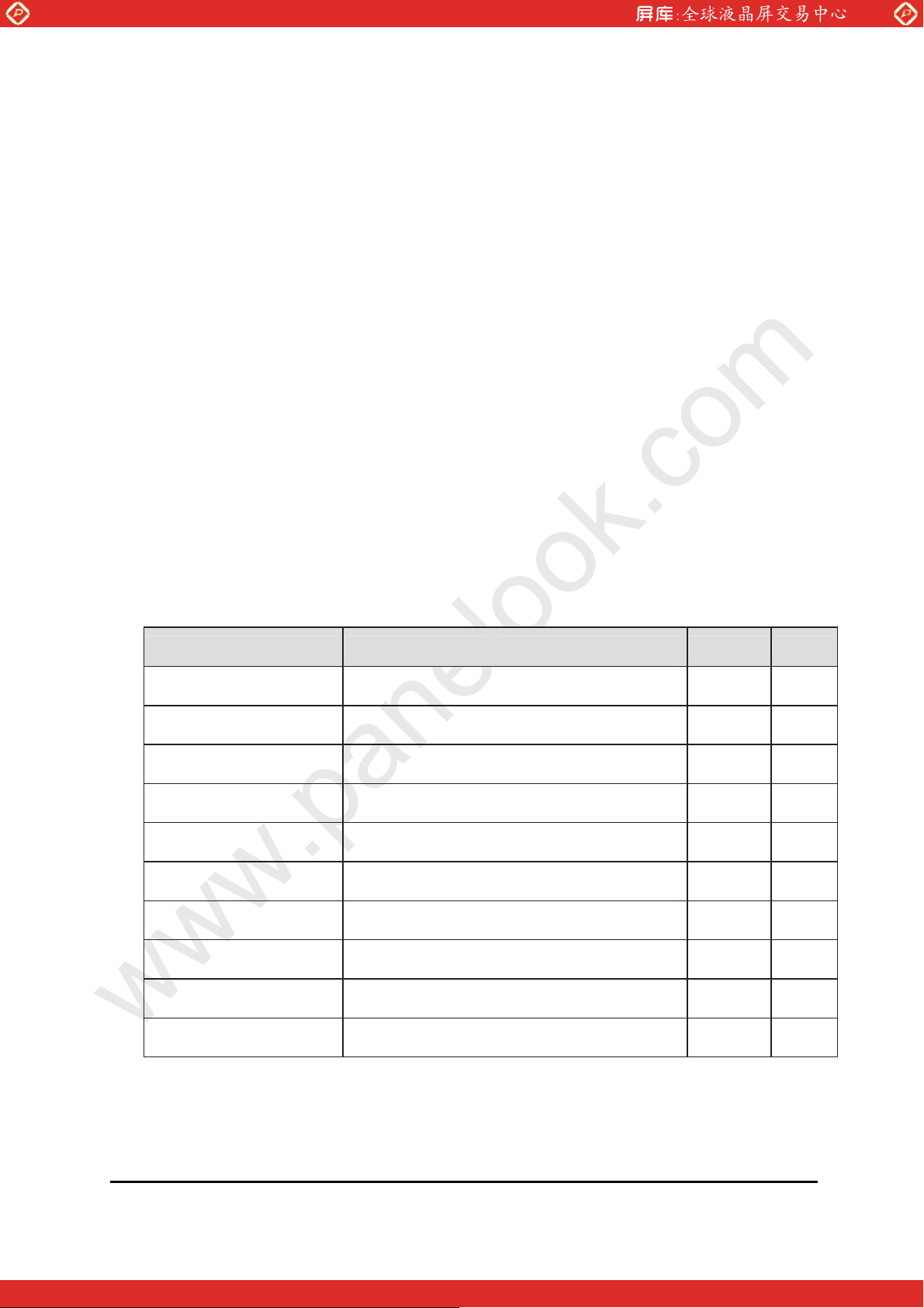
2. PHYSICAL SPECIFICATIONS
Item Specifications unit Note
Active area
Number of pixels
Pixel pitch 0.240(H) × 0.240(V) mm
Pixel arrangement RGB Vertical stripe
Display colors 262,144 colors
Display mode Normally Black
Dimensional outline 270.0 (H) ×199.0 (V) ×4.8 @Lamp mm (2)
245.76 (H) ×184.32 (V) mm
1024(H) × 768(V) pixels
Weight 305 (Typ.) gram
Back-light Bottom edge side 1-CCFL type (1)
Surface treatment Haze 25, Anti-glare & hard-coating (3H)
Note : 1. CCFL (Cold Cathode Fluorescent Lamp)
2. LCM Height: 4.8[mm]Typ.(Lamp) , 6.7[mm] Typ(Pouch)
Date : 2009/08/03 AMPIRE CO., LTD.
One step solution for LCD / PDP / OLED panel application: Datasheet, inventory and accessory!
3
www.panelook.com
Page 4
Global LCD Panel Exchange Center
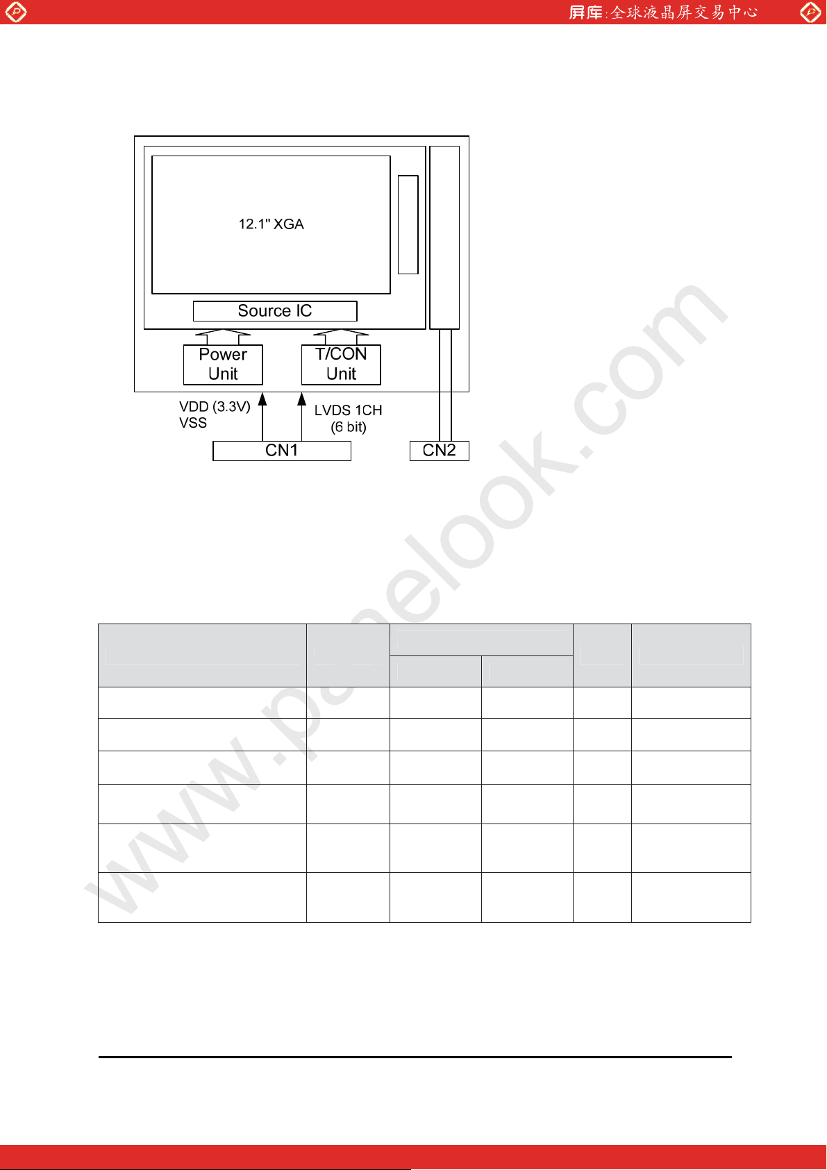
2-1 Block Diagram
www.panelook.com
CCFL
Gate IC
Lamp
Lamp Reflector
3. ABSOLUTE MAX. RATINGS
The followings are maximum values which, if exceed, may cause faulty operation
or damage to the unit.
[VSS = GND = 0V]
Values
Item Symbol
Min. Max.
Power Input Voltage VDD VSS-0.3 4.0 V Ta = 25 ±2 к
Logic Input Voltage VIN VSS-0.3 VDD+0.3 V
Back-light Lamp Current IBL 2.0 6.0 mA
Back-light Lamp
Frequency
Operating Temperature
(Humidity)
FL 30 80 KHz
TOP
RH
0
+50
80
UNIT Note
к
%
Љ40к
ʳ
Storage Temperature
(Humidity)
TSP
RH
-20
+60
90
к
%
Date : 2009/08/03 AMPIRE CO., LTD.
One step solution for LCD / PDP / OLED panel application: Datasheet, inventory and accessory!
Љ40к
4
www.panelook.com
Page 5
Global LCD Panel Exchange Center
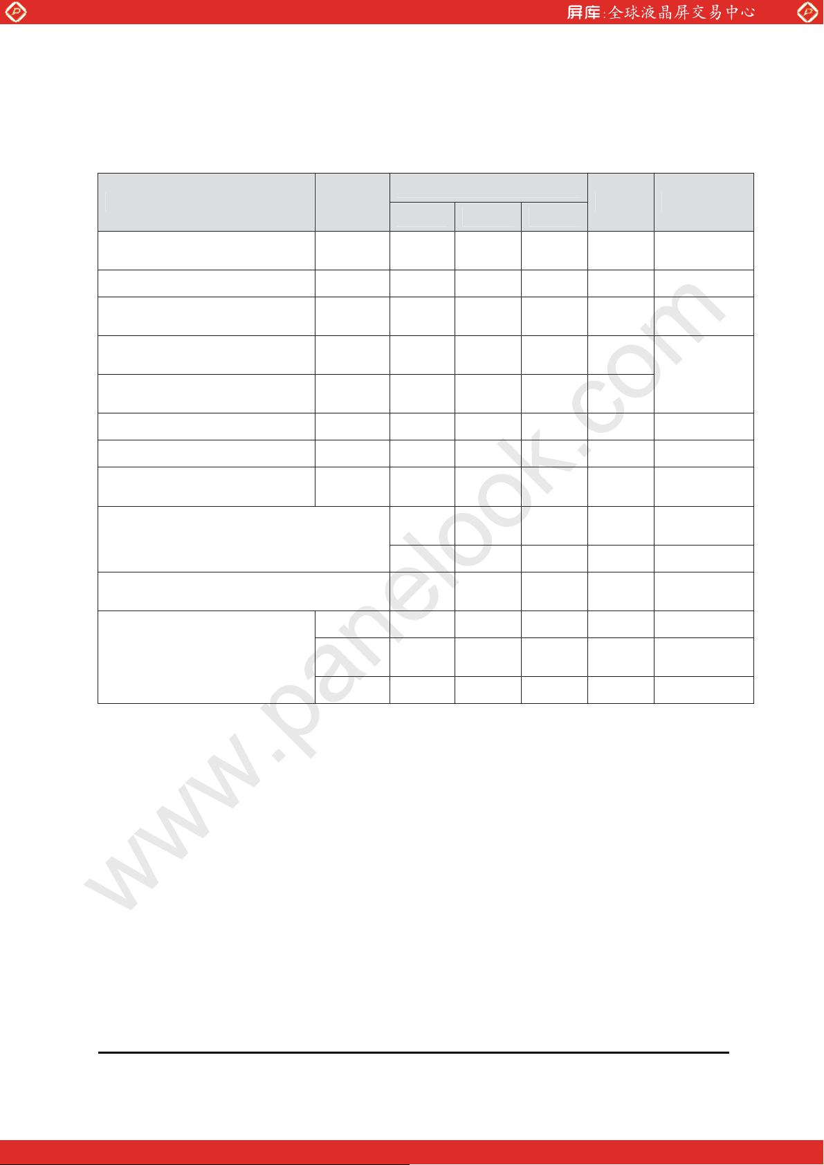
4. ELECTRICAL CHARACTERISTICS
4-1 Typical Operation Conditions
Item Symbol
Power Supply Voltage VDD 3.0 3.3 3.6 V
Power Supply Current IDD -- 240 -- mA (1)
Permissible Input Ripple
Voltage
High Level Differential
Input Threshold Voltage
Low Level Differential Input
Threshold Voltage
Back-light Lamp Voltage VBL -- 600 -- Vrms
www.panelook.com
Values
Unit Note
MIN TYP MAX
VRF -- -- 100 mV VDD=3.3V
VIH -- -- +100 mV
VIL -100 -- -- mV
VCM=1.2V
typ.
Back-light Lamp Current IBL 2.0 5.0 6.0 mArm
Back-light Lamp
Frequency
Lamp Start Voltage
FL 30 60 80 KHz (2)
-- -- 950 Vrms
Ta=25к,
(3)
-- -- 1150 Vrms Ta=0к, (3)
Lamp Life 10K -- -- Hrs
IBL=
2.0~6.0mA
PD -- 0.7 -- W
Power Consumption
PBL -- 3.0 -- W
IBL=5.0mA
, (4)
Ptotal -- 3.7 -- W
Notes : 1. The supply voltage is measured and specified at the interface connector of
LCM.
The current draw and power consumption specified is for VDD=3.3V,
Frame rate = 60Hz and Clock frequency=65MHz.
Test Pattern of power supply currnent.
a) Typ:
Vertical color bar pattern
b) Max:
Gray 28 @ Vertical 2 Skip line pattern
2. The lamp frequency should be selected as different as possible from the
horizontal synchronous frequency and its harmonics to avoid interference,
which may cause line flow on the display
3. The voltage above this value should be applied to the lamps for more than
1 second to startup. Otherwise the lamps may not to be turned on.
4. Calculated value for reference (VBL × IBL) excluding inverter loss.
Date : 2009/08/03 AMPIRE CO., LTD.
One step solution for LCD / PDP / OLED panel application: Datasheet, inventory and accessory!
5
www.panelook.com
Page 6
Global LCD Panel Exchange Center
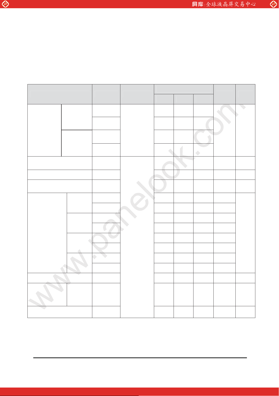
5. Optical Specifications
The measurement shall be executed after 30 minutes warm-up period.
Measuring equipment: TOPCON-BM5.
[VDD=3.3V, Frame rate=60Hz, Clock=65MHz, IBL = 5.0mA, Ta = 25±2к]
Item Symbol Condition
Horizontal
Viewing
Angle
Range
Vertical
www.panelook.com
Values
Unit Note
Min. Typ. Max.
3 89 90
9 89 90
CR > 10
Deg. (1)
12 89 90
6
89 90
Luminance Contrast
ratio
CR -- 450 -- (2)
Luminance of white YL -- 180 -- cd/m2 (3)
White luminance
uniformity
Y -- -- 1.4 (4)
Xw 0.282 0.312 0.342
White
Yw 0.307 0.337 0.367
Color Cord.
XR 0.547 0.577 0.607
Red
YR 0.314 0.344 0.374
XG 0.281 0.311 0.341
Green
YG 0.511 0.541 0.571
= 0°
(Center)
Normal
Viewing
Angle
(5)
XB 0.120 0.150 0.180
Blue
YB 0.114 0.144 0.174
Color Reproduction 40 %
Response
Time
Ttotal
(Tr+Td)
Ttotal 40 ms (6)
Cross Talk CT
-- -- 2.0 % (7)
Date : 2009/08/03 AMPIRE CO., LTD.
One step solution for LCD / PDP / OLED panel application: Datasheet, inventory and accessory!
(Table 4.)
6
www.panelook.com
Page 7
Global LCD Panel Exchange Center
Note :
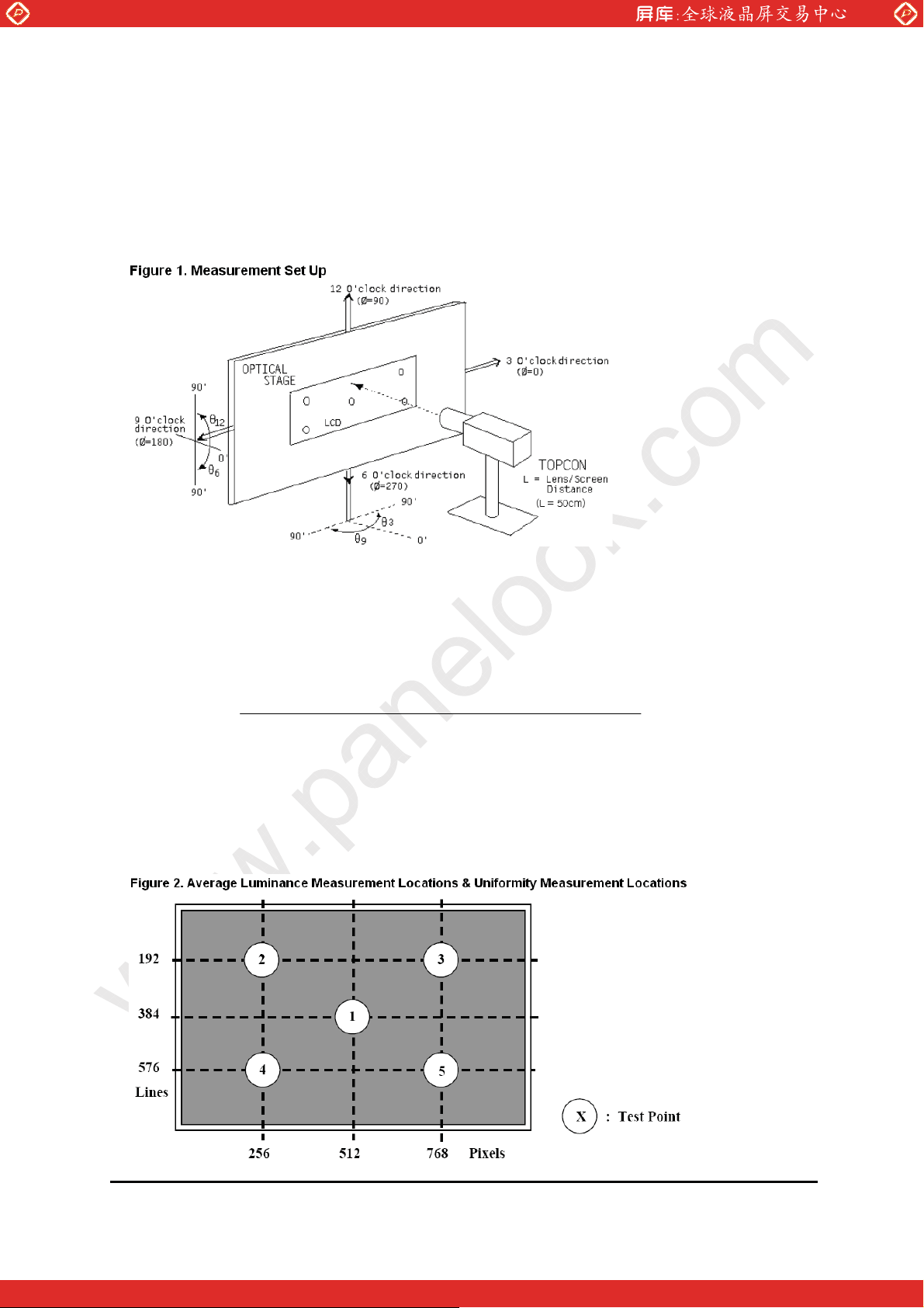
1. Viewing angle is the angle at which the contrast ratio is greater than 10. The
viewing are determined for the horizontal or 3, 9 o’clock direction and the vertical
or 6, 12 o’clock direction with respect to the optical axis which is normal to the LCD
surface
www.panelook.com
2. Contrast measurements shall be made at viewing angle of = 0° and at the center
of the LCD surface. Luminance shall be measured with all pixels in the view field
set first to white, then to the dark (black) state. Luminance Contrast Ratio (CR) is
defined mathematically.
Luminance when displaying a white raster
CR =
Luminance when displaying a black raster
3. Luminance of white is defined as a center point(#1) on LCD surface. Luminance
shall be measured with all pixels in the view field set first to white. This
measurement shall be taken at the locations shown in FIGURE 2 for a total of the
measurements per display.
Date : 2009/08/03 AMPIRE CO., LTD.
One step solution for LCD / PDP / OLED panel application: Datasheet, inventory and accessory!
7
www.panelook.com
Page 8
Global LCD Panel Exchange Center
4. The White luminance uniformity on LCD surface is then expressed as : Y =
Minimum Luminance of 5 points / Maximum Luminance of 5 points (see FIGURE 2
shown in Appendix).
5.
The color chromaticity coordinates specified in Table 4 shall be calculated from the
spectral data measured with all pixels first in red, green, blue and white.
Measurements shall be made at the center of the panel.
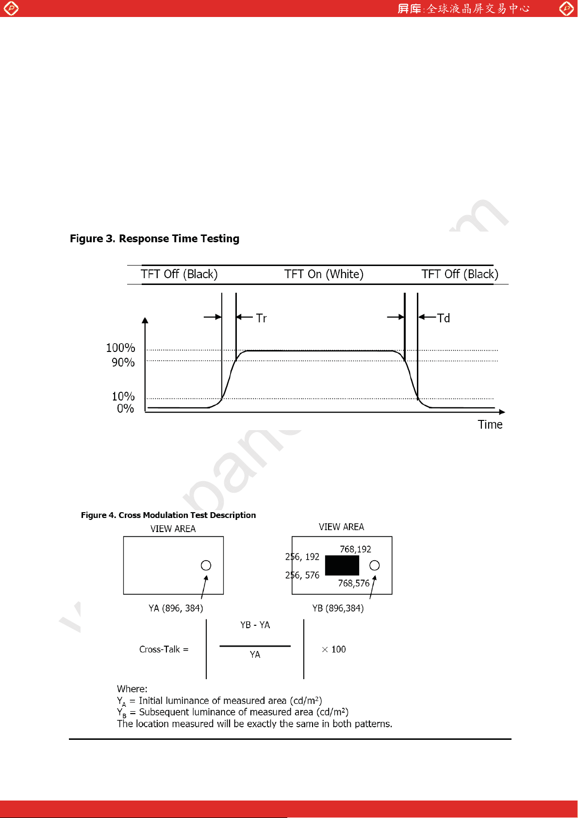
6. The electro-optical response time measurements shall be made as FIGURE 3
shown in Appendix by switching the “data” input signal ON and OFF. The times
www.panelook.com
needed for the luminance to change from 10% to 90% is Tr, and 90% to 10% is Td.
7. Cross-Talk of one area of the LCD surface by another shall be measured by
comparing the luminance (YA) of a 25mm diameter area, with all display pixels set
to a gray level, to the luminance (YB) of that same area when any adjacent area is
driven dark. (See FIGURE 4 shown in Appendix).
Date : 2009/08/03 AMPIRE CO., LTD.
One step solution for LCD / PDP / OLED panel application: Datasheet, inventory and accessory!
8
www.panelook.com
Page 9
Global LCD Panel Exchange Center
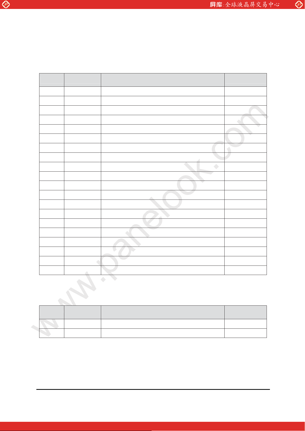
6. INTERFACE
6.1 Electrical Interface Connection
CN1 : Interface Connector : Hirose/DF19L-20P-1H or equivalent
User side Connector : Hirose/DF19G-20S-1C or equivalent
Pin No. Symbol Description Note
1 VDD1 Power Supply: +3.3V
2 VDD2 Power Supply: +3.3V
3 VSS Ground
4 VSS Ground
5 RIN0- LVDS Negative data signal (-) Tx pin # 48
6 RIN0+ LVDS Positive data signal (+) Tx pin # 47
7 VSS Ground
www.panelook.com
8 RIN1- LVDS Negative data signal (-) Tx pin # 46
9 RIN1+ LVDS Positive data signal (+) Tx pin # 45
10 VSS Ground
11 RIN2- LVDS Negative data signal (-) Tx pin # 42
12 RIN2+ LVDS Positive data signal (+) Tx pin # 41
13 VSS Ground
14 RCLKIN- LVDS Negative clock signal (-) Tx pin # 40
15 RCLKIN+ LVDS Positive clock signal (+) Tx pin # 39
16 VSS Ground
17 NC No Connection
18 NC No Connection
19 VSS Ground
20 VSS Ground
6.2 Back-light interface
CN1 : Interface Connector : JST/BHSR-02VS-1 or equivalent
User side Connector : JST/MS02B-BHSS-1 or equivalent
Pin No. Input Description Note
1 HOT High voltage
2 COLD Ground
Date : 2009/08/03 AMPIRE CO., LTD.
One step solution for LCD / PDP / OLED panel application: Datasheet, inventory and accessory!
9
www.panelook.com
Page 10
Global LCD Panel Exchange Center
6.3 LVDS Interface
LVDS Transmitter : THC63LVDM83A or equivalent.
Transmitter Interface DF19L-14P-1HInput
Signal
Pin No. Pin No. System(TX) TFT-LCD(RX) Pin No.
R0 51
R1 52
R2 54
R3 55
R4 56
R5 3
G0 4
G1 6
G2 7
G3 11
G4 12
G5 14
B0 15
B1 19
B2 20
B3 22
B4 23
B5 24
HSYNC 27
VSYNC 28
DE 30
MCLK 31 40 CLKOUT- CLKIN- 11
39 CLKOUT+ CLKIN+ 12
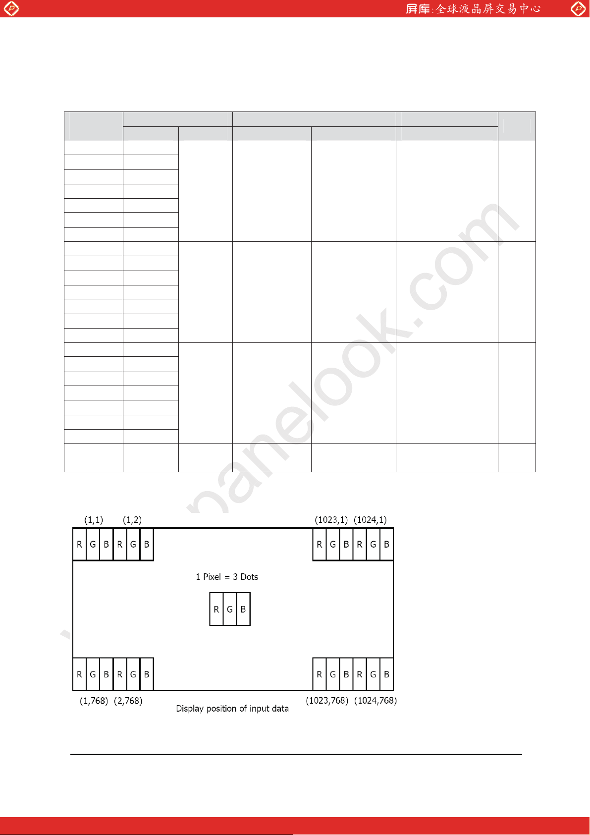
6.4 Data Input Format
48
47
46
45
42
41
www.panelook.com
OUT0-
OUT0+
OUT1-
OUT1+
OUT2-
OUT2+
IN0-
IN0+
IN1-
IN1+
IN2-
IN2+
5
6
7
8
9
10
Note
Date : 2009/08/03 AMPIRE CO., LTD.
One step solution for LCD / PDP / OLED panel application: Datasheet, inventory and accessory!
10
www.panelook.com
Page 11
Global LCD Panel Exchange Center
7. Signal Timing Specifications
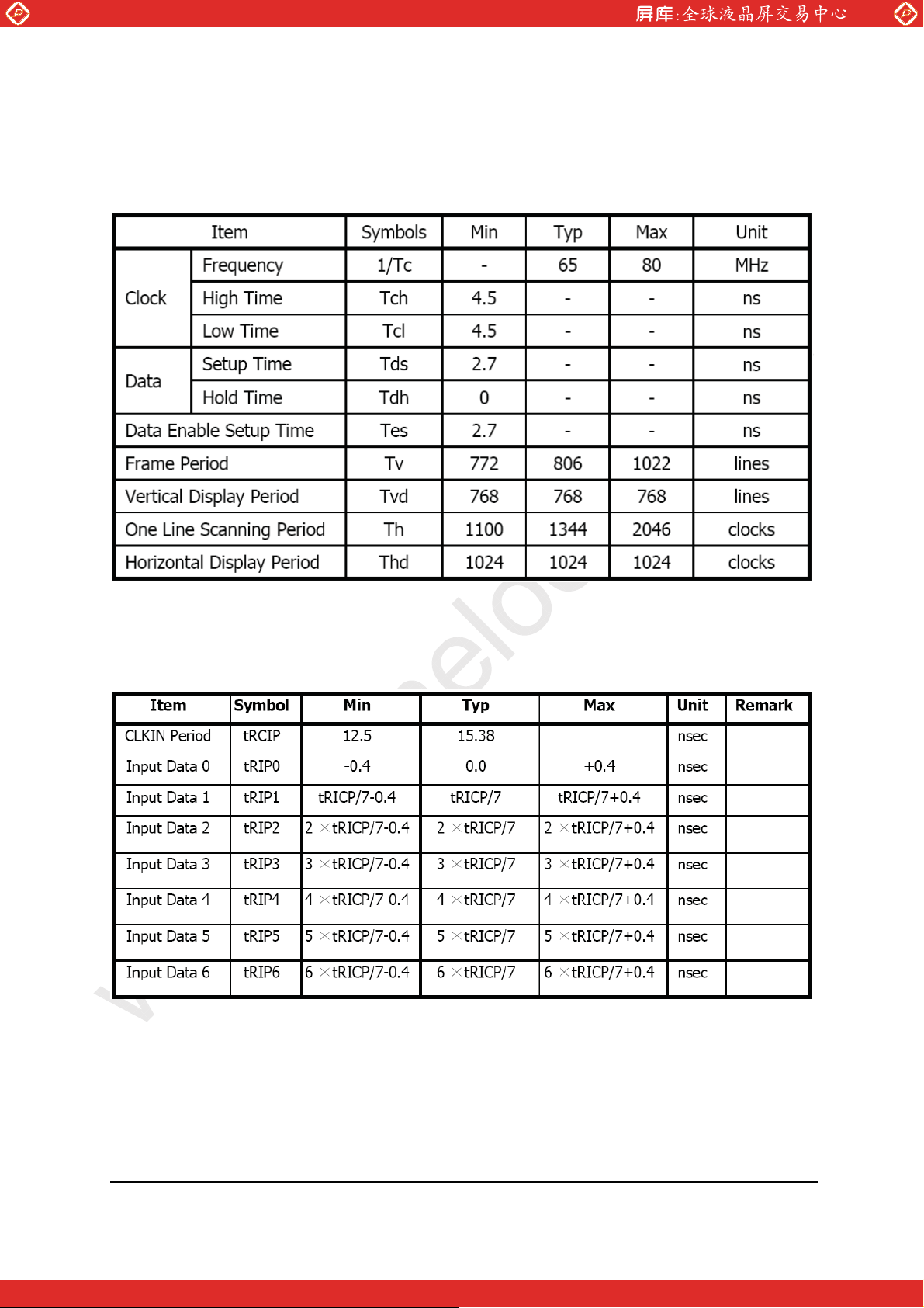
7-1 The 12.1”XGA LCM is operated by the only DE (Data enable) mode
(LVDS Transmitter Input)
www.panelook.com
7-2 LVDS Rx Interface Timing Parameter
The specification of the LVDS Rx interface timing parameter
<LVDS Rx Interface Timing Specification>
Date : 2009/08/03 AMPIRE CO., LTD.
One step solution for LCD / PDP / OLED panel application: Datasheet, inventory and accessory!
11
www.panelook.com
Page 12
Global LCD Panel Exchange Center
www.panelook.com
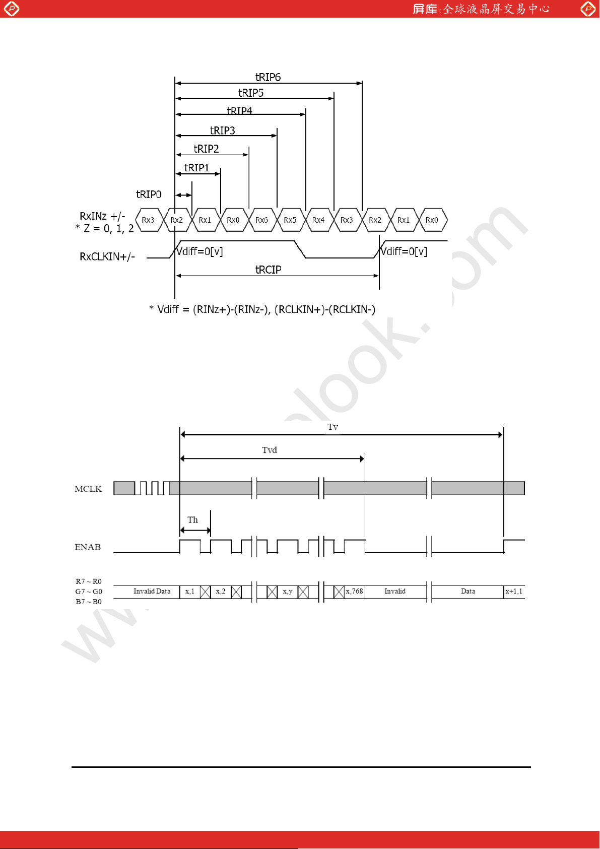
8. Signal Timing Waveforms Of Interface Signal (DE Mode)
8.1 Vertical Timing Waveforms
Date : 2009/08/03 AMPIRE CO., LTD.
One step solution for LCD / PDP / OLED panel application: Datasheet, inventory and accessory!
12
www.panelook.com
Page 13
Global LCD Panel Exchange Center
www.panelook.com
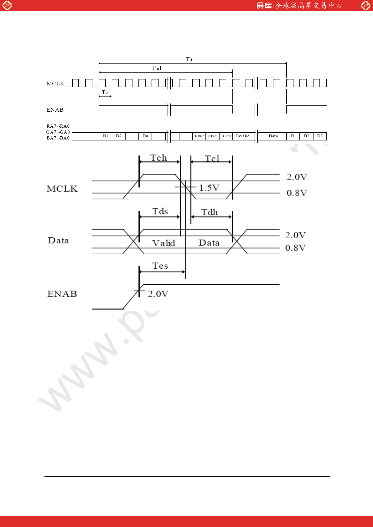
8.1 Horizontal Timing Waveforms
Date : 2009/08/03 AMPIRE CO., LTD.
One step solution for LCD / PDP / OLED panel application: Datasheet, inventory and accessory!
13
www.panelook.com
Page 14
Global LCD Panel Exchange Center
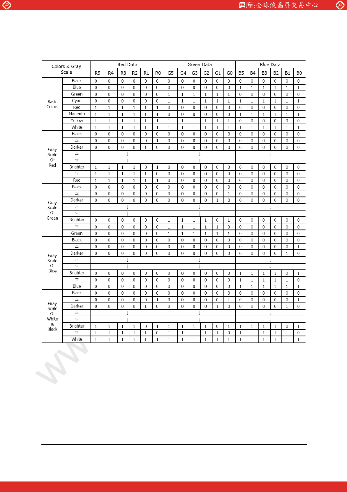
9. Input Signals, Basic Display Coors & Gray Scale of Colors
www.panelook.com
Date : 2009/08/03 AMPIRE CO., LTD.
One step solution for LCD / PDP / OLED panel application: Datasheet, inventory and accessory!
14
www.panelook.com
Page 15
Global LCD Panel Exchange Center
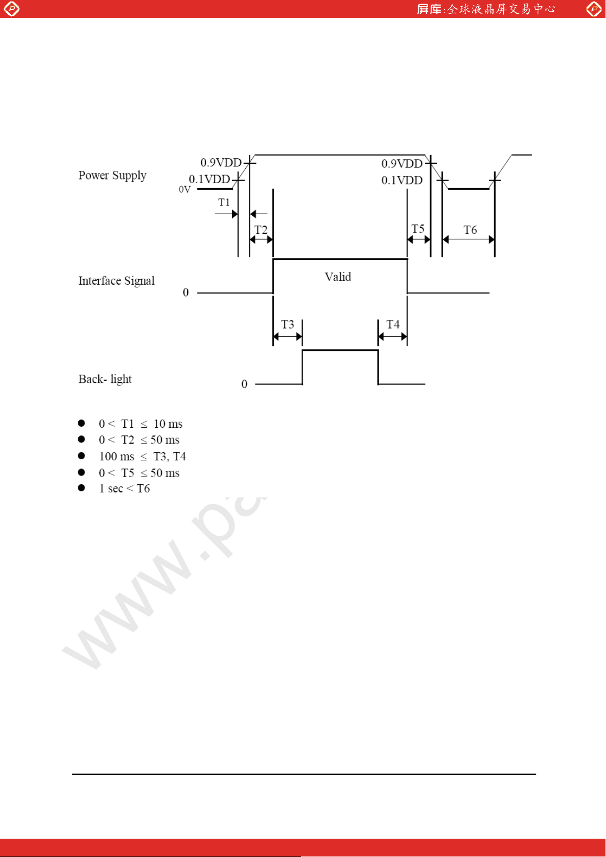
10. Power Sequence
To prevent a latch-up or DC operation of the LCD module, the power on/off sequence
shall be as shown in below
www.panelook.com
Notes :
1. When the power supply VDD is 0V, Keep the level of input signals on the low or
keep high impedance.
2. Do not keep the interface signal high impedance when power is on.
3. Back Light must be turn on after power for logic and interface signal are valid.
Date : 2009/08/03 AMPIRE CO., LTD.
15
One step solution for LCD / PDP / OLED panel application: Datasheet, inventory and accessory!
www.panelook.com
Page 16
Global LCD Panel Exchange Center
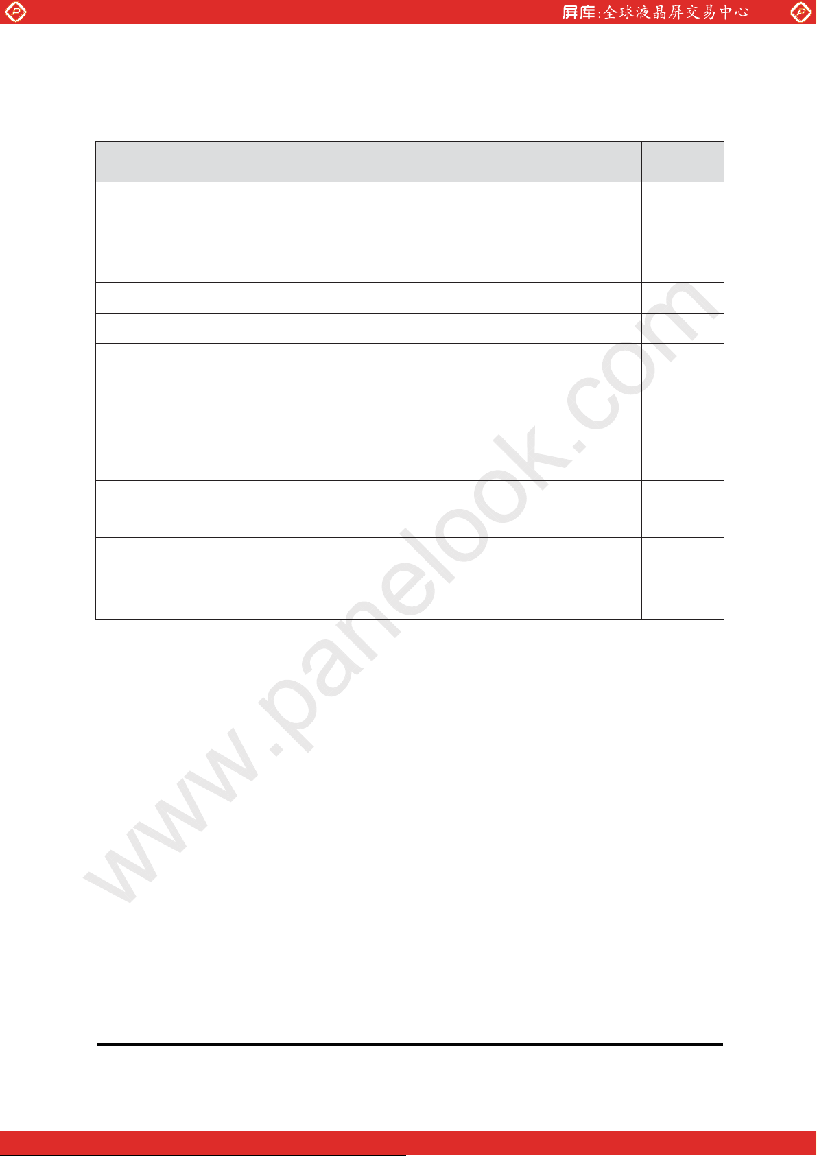
11. RELIABILITY TEST CONDITIONS
Item Test Conditions Note
High temperature storage test Ta = 60 °C, 240 hrs
Low temperature storage test Ta = -20 °C, 240 hrs
www.panelook.com
High temperature & high
humidity operation test
Ta = 50 к, 80%RH, 240hrs
High temperature operation test Ta = 50 °C, 240 hrs
Low temperature operation test Ta = 0 °C, 240 hrs
Thermal shock Ta = -20 °C ~ 60 °C (0.5H), 100 cycle
Vibration test
(non-operating)
Shock test
(non-operating)
Electro-Static Discharge Test
(non-operating)
Frequency : 10~500Hz
Gravity/AMP : 1.5G
Period : X,Y,Z 30min
Gravity : 150G
Pulse width : 6ms, half sine wave
±X, ±Y, ±Z Once for each direction
Air : 150pF 330ohm 15KV
Contact : 150pF, 330ohm, 8KV
Date : 2009/08/03 AMPIRE CO., LTD.
One step solution for LCD / PDP / OLED panel application: Datasheet, inventory and accessory!
16
www.panelook.com
Page 17
Global LCD Panel Exchange Center
12. HANDLING & CAUTIONS
12.1 Cautions when taking out the module
Pick the pouch only, when taking out module from a shipping package.
12.2 Cautions for handling the module
12.2.1 As the electrostatic discharges may break the LCD module, handle
the LCD module with care. Peel a protection sheet off from the
www.panelook.com
LCD panel surface as slowly as possible.
12.2.2 As the LCD panel and backlight element are made from fragile glass
material, impulse and pressure to the LCD module should be avoided.
12.2.3 As the surface of the polarizer is very soft and easily scratched,
use a soft dry cloth without chemicals for cleaning.
12.2.4 Do not pull the interface connector in or out while the LCD module
is operating.
12.2.5 Put the module display side down on a flat horizontal plane.
12.2.6 Handle connectors and cables with care.
12.3 Cautions for the operation
12.3.1 When the module is operating, do not lose MCLK, DE signals. If any one
of these signals were lost, the LCD panel would be damaged.
12.3.2 Obey the supply voltage sequence. If wrong sequence were applied, the
module would be damaged.
12.4 Cautions for the atmosphere
12.4.1 Dewdrop atmosphere should be avoided.
12.4.2 Do not store and/or operate the LCD module in a high temperature and/or
humidity atmosphere. Storage in an electro-conductive polymer-packing
pouch and under relatively low temperature atmosphere is recommended.
12.5 Cautions for the module characteristics
12.5.1 Do not apply fixed pattern data signal to the LCD module at product
aging.
12.5.2 Applying fixed pattern for a long time may cause image sticking.
12.6 Other cautions
12.6.1 Do not disassemble and/or re-assemble LCD module.
12.6.2 Do not re-adjust variable resistor or switch etc.
12.6.3 When returning the module for repair or etc, please pack the module not
to be broken. We recommend using the original shipping packages.
12.6.4 AMIPRE will provide one year warrantee for all products and three
months warrantee for all repairing products.
Date : 2009/08/03 AMPIRE CO., LTD.
17
One step solution for LCD / PDP / OLED panel application: Datasheet, inventory and accessory!
www.panelook.com
Page 18
Global LCD Panel Exchange Center
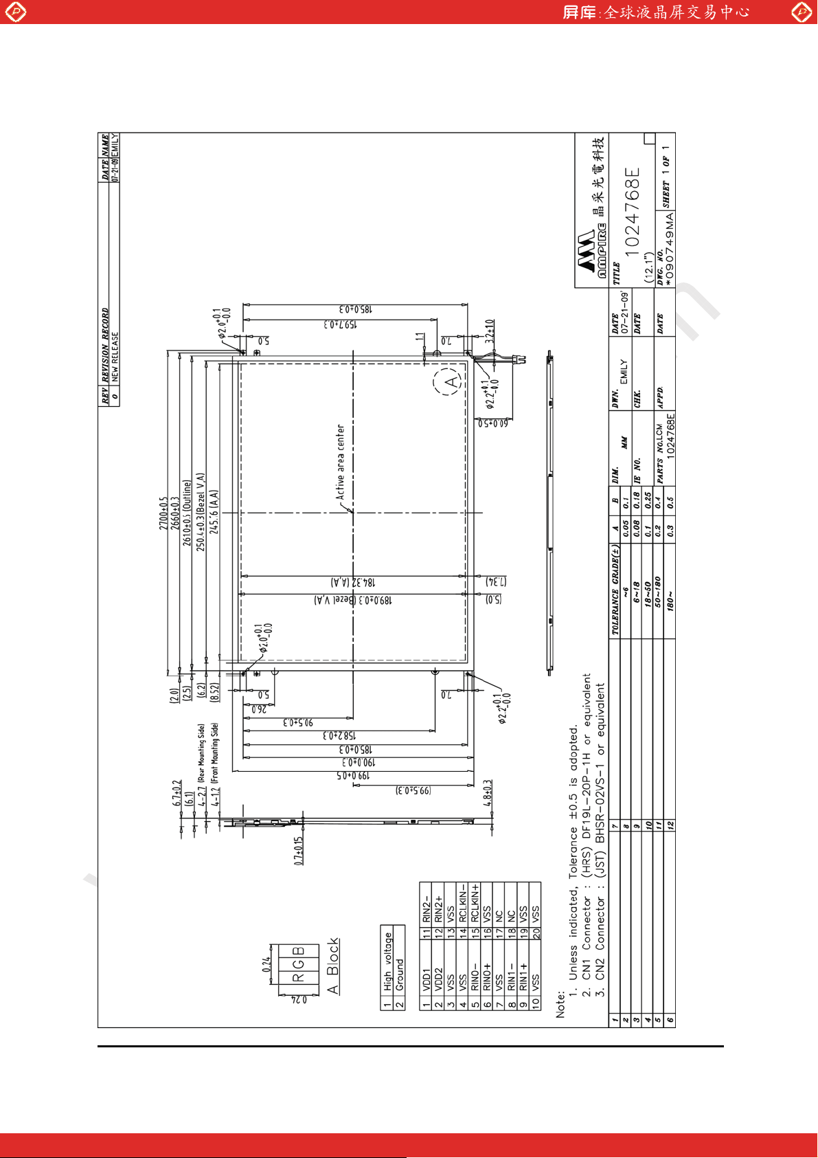
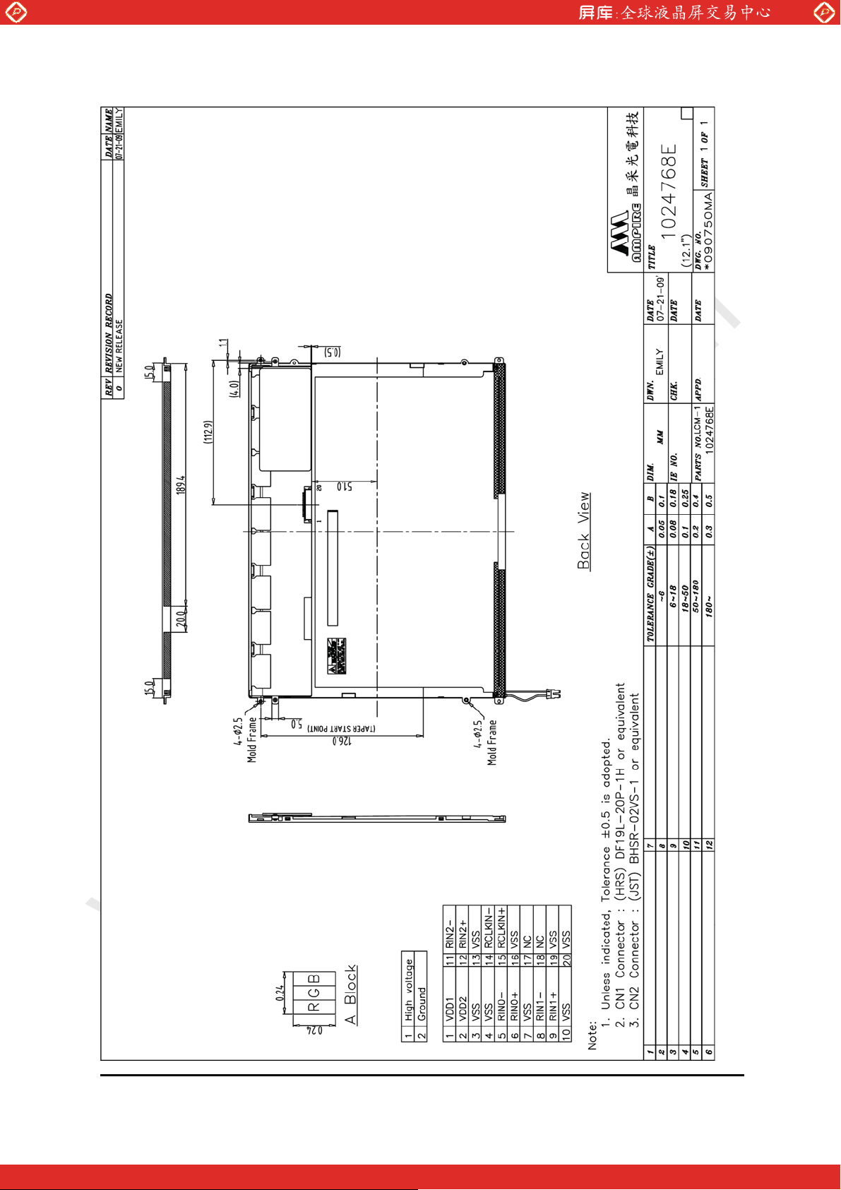
13. OUTLINE DIMENSION
www.panelook.com
Date : 2009/08/03 AMPIRE CO., LTD.
One step solution for LCD / PDP / OLED panel application: Datasheet, inventory and accessory!
18
www.panelook.com
Page 19
Global LCD Panel Exchange Center
www.panelook.com
Date : 2009/08/03 AMPIRE CO., LTD.
One step solution for LCD / PDP / OLED panel application: Datasheet, inventory and accessory!
19
www.panelook.com
 Loading...