

Amphony 1550 Installation Guide

User and Installation
Guide
5.8 GHz DIGITAL Wireless
Audio Transmitter / Amplifier
Model 1550
RR

User and Installation Guide
Unpacking: Check that this package contains:
One 5.8 GHz Digital Audio transmitter - Model 1550, two 5.8 GHz Digital
Audio amplifiers - Model 1550, one small and two large AC adapters
(wallwarts), four short speaker cables, one RCA audio cable.
RR
Step 1Step 1
Connecting the transmitter
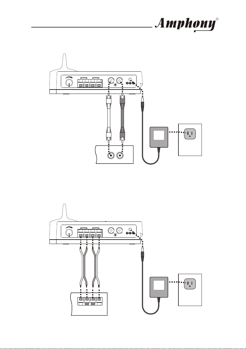
The transmitter connects either to a standard line-out audio interface via the
supplied RCA cable or to an amplified speaker output via the supplied short
speaker cables.
If the transmitter is connected via speaker cables, observe the polarity of the
cable connection to ensure that the transmitter will be fed with a correct
polarity signal. If one of the cables is switched (reversed), one speaker will
receive an opposite polarity signal which will degrade sound performance.
The transmitter can also be connected to other audio outputs by using an
appropriate adapter.
Connect the supplied small AC adapter’s barrel-shaped plug into the DC 9V
jack, and then plug the transformer into a standard AC outlet. We recommend
the use of a surge protector to protect the transmitter from power surges.
ATTENTION!
Do not use both the speaker cables and RCA cable. Do not connect
speakers to the transmitter. Do not connect the large AC adapter to
the transmitter.
Copyright (C) 2004 Amphony. All rights reserved.
The information contained herein is subject to change without notice.
Revisions may be issued to advise of such changes and/or additions.
All product names, trade names, or corporate names mentioned in this
document are acknowledged to be the proprietary property of the registered
owners.
FCC ID PMJT1500
This device complies with part 15 of the FCC Rules. Operation is subjected
to the following two conditions: 1) This device may not cause harmful
interference and 2) this device must accept any interference received,
including interference that may cause undesired operation.
Caution: Any changes or modifications not expressly approved by the party
responsible for compliance could void the user's authority to operate the
equipment.
Page 1
User and Installation Guide
Using the transmitter RCA audio input:
RR
L
R
DC 9V
L R
Transmitter
AUDIO
LINE OUT
L R
Audio Source
Using the transmitter speaker audio input:
L
R
DC 9V
L R
AC adapter
DC 9 V
300 mA
Power outlet
Transmitter
L R
SPEAKER OUT
Audio Source
AC adapter
DC 9 V
300 mA
Power outlet
Page 2
User and Installation Guide
RR
Step 2Step 2
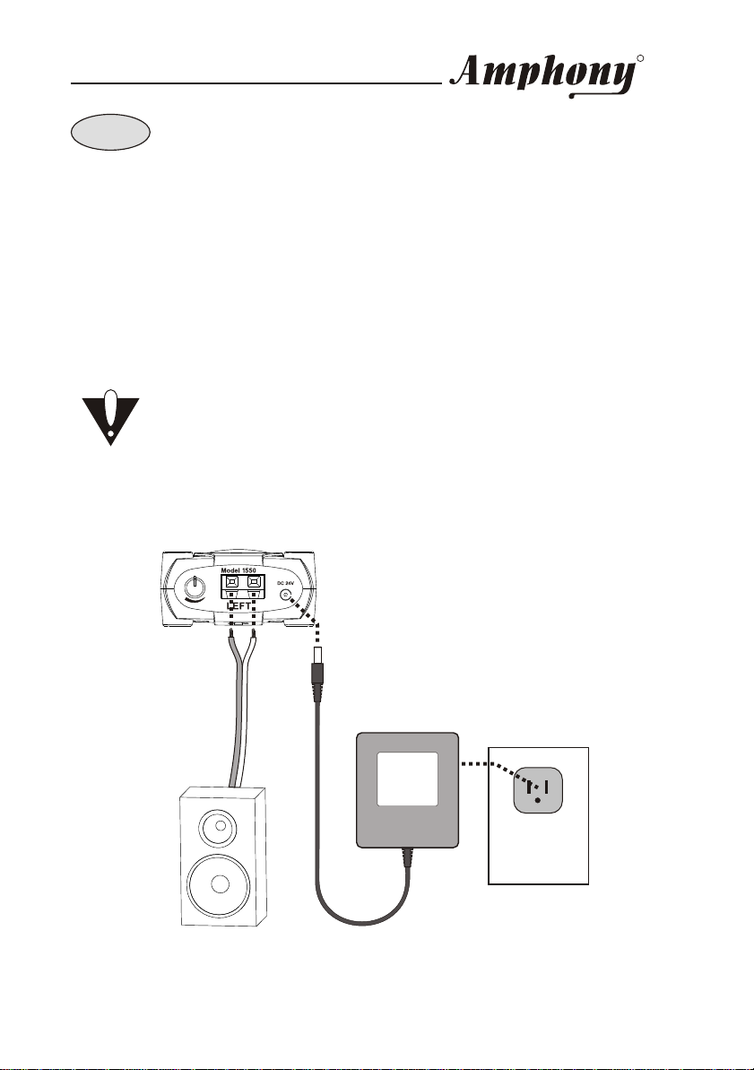
Connecting the amplifiers
Connect the DC power input of each amplifier with the supplied large 24 V AC
adapter (wallwart). The use of a surge protector is recommended to protect the
amplifiers from power surges which may damage the amplifiers and connected
speakers or may cause audio dropouts.
Each amplifier connects to regular passive loudspeakers via the supplied speaker
cable. Observe the correct polarity when connecting the speakers.
Connect the left speaker to the amplifier marked “LEFT”. Connect the right
speaker to the amplifier marked “RIGHT”.
ATTENTION!
Never short circuit any amplifier audio output since this may
damage the amplifier. A clicking noise may be generated during
amplifier power up. Therefore, it is recommended to connect power
to the amplifier prior to connecting the speakers.
Speaker connections:
Amplifier for left speaker
AC adapter
DC 24 V
DC 24 V
1000 mA
1000 mA
Power outlet
Left speaker
Connect the right speaker to the amplifier for the right speaker similarly.
Page 3
 Loading...