

Page 1
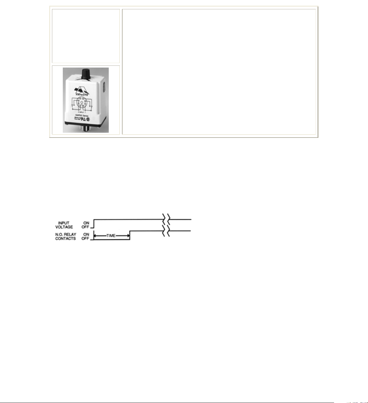
SWPDC
Series
TDR
Timing Mode:
Delay on operate timing cycle begins upon application of input power. The relay contacts
transfer at the end of the delay period and will remain transferred until input voltage is
removed. Reset occurs when input voltage is removed.
Timing Diagram:
… Solid state CMOS digital circuitry
… Delay on operate timing mode
… DPDT (2 form C) isolated 10 ampere relay contacts
… Timing selection: 5 position binary coded Dip Switch plus
vernier knob adjustment
… Twenty overlapping timing ranges covering .25 secs. to
160 hours.
… UL File#E96739 (M)
… CSA File #LR62586
Contact Information:
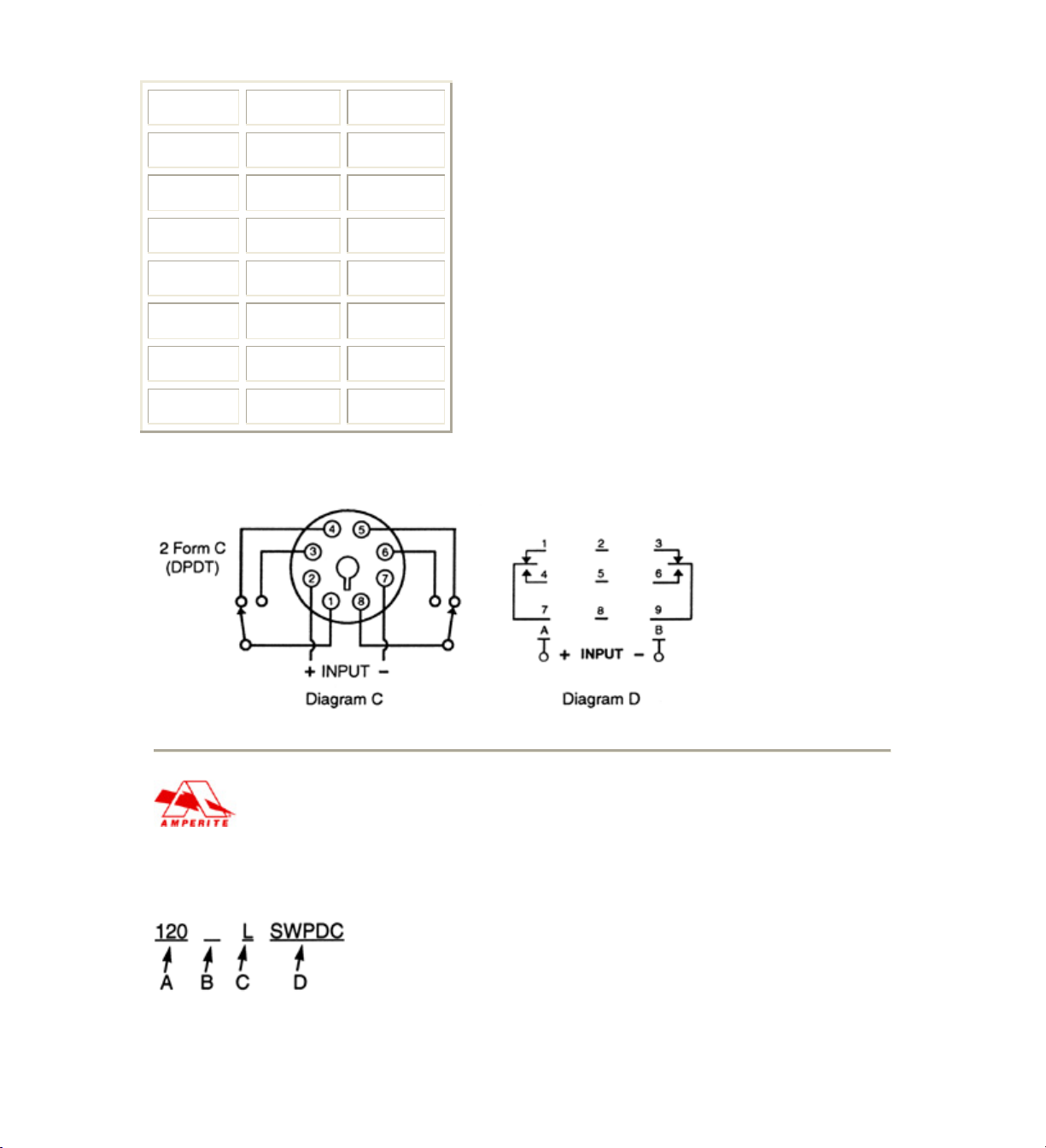
Arrangement: 2 form C (DPDT) - Diagram C
Contact Material: Silver - Cadmium Oxide
Rating (Resistive): 10A @ 240V AC Resistive, 15A @ 30V DC Resistive, 15A @ 120V
AC Resistive, 1/3 HP @ 120V AC, 1/2 HP @ 250V AC
Expected Life @ 25°C: 10 Million operations, Mechanical 100,000 operations minimum
at rated loads
Environmental Information:
Temperature Range: Storage: -60°C to +105°C (-76°F to +221°F) Operating: -45°C to
+70°C (-49°F to +158°F)
Mechanical Information:
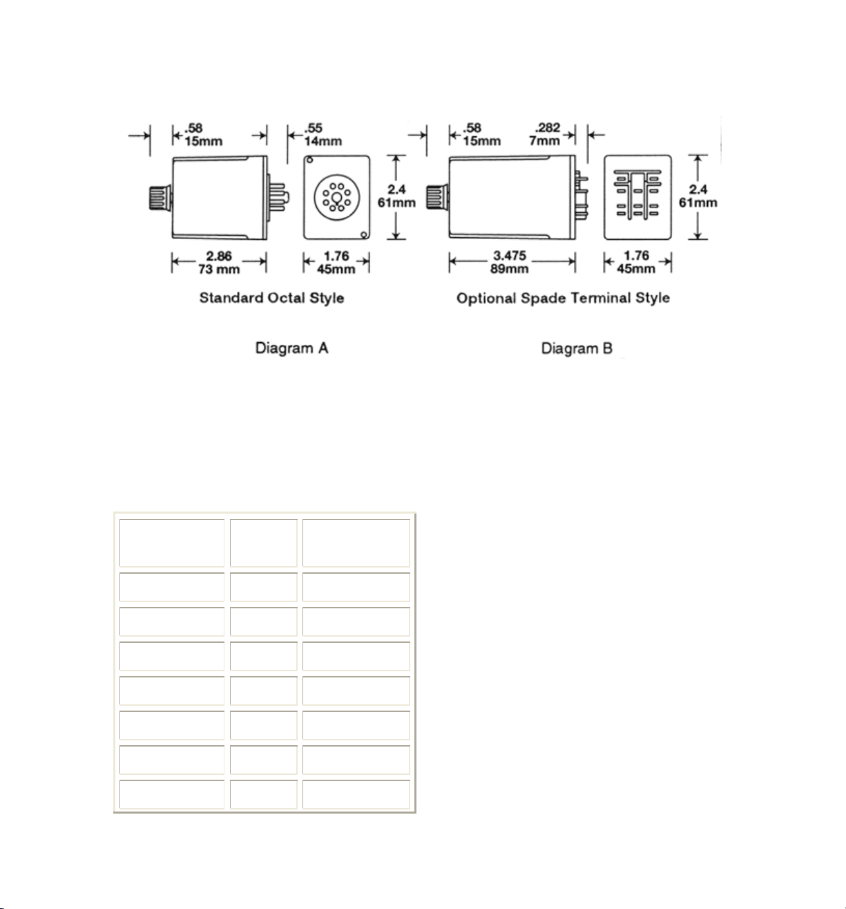
Termination: 8 pin Octal Style Plug or 11 pin spade terminals. (Diagram C&D).
Page 2
Enclosure: White plastic case with a dial scale for reference only. LSWPDC version has a
black case.
Weight: 4oz (114g) approx.
Outline Dimensions:
Timing Specifications:
Standard Timing: The SWPDC has 20 overlapping timing ranges covering 0.25 secs. to
160 hours. Timing is user selectable by means of a 5 position binary coded Dip Switch
and a knob adjustable potentiometer allowing the time delay within the selected timing
range to be set precisely.
Timing Adjustment: 5 position binary Dip Switch coded as follows:
Timing Range
Measure
Switch Setting
12345
.25 - 1.25 Seconds 00101
.5 - 2.5 Seconds 10101
1 - 5 Sec. Seconds 01101
2 - 10 Seconds 11101
4 - 20 Seconds 00011
8 - 40 Seconds 10011
16 - 80 Seconds 01011
Page 3
32 - 160 Seconds 11011
1 - 5 Minutes 00111
2 - 10 Minutes 10111
4 - 20 Minutes 01111
9 - 42 Minutes 11111
17 - 85 Minutes 00010
34 - 170 Minutes 10010
1 - 5 Hours 01010
2 -10 Hours 11010
4 - 20 Hours 00110
8 - 40 Hours 10110
16 - 80 Hours 01110
32 - 160 Hours 11110
Set Switches #1 thru #5 to desired position where:
1 = On, 0 = Off
Repeatability: ±1%
Release Time: 60 ms typical, 100 ms maximum
Timing Cycle Interrupt Transfer: none
Reset: Upon interruption of power
Initial Dielectric Strength:
Between open contacts: 1000V RMS,
Between adjacent contacts: 1500V RMS,
Between contacts & coil: 1500V RMS
Input Information:
Voltage: 12V - AC or DC, 24V - AC or DC, 48V DC, 110V DC, 120V AC. Other
voltages are available.
Power Requirement: AC inputs: 3 VA or less, DC inputs: 3 Watts of less
Transient Protection: 1 JOULE MOV
Polarity Protection: On DC inputs - Yes
Page 4
Input Voltages & Limits:
Nominal Minimum
Maximum
12V AC 10V 14V
24V AC 20V 28V
120V AC
105V 130V
12V DC 11V 14V
24V DC 20V 32V
48V DC 41V 55V
110V DC
95V 125V
Wiring Diagram:
Ordering Information:
Definition of a part number for the Amperite SWPDC Series Time Delay Relay.
Example:
Page 5

A: Denotes nominal input voltage. Voltages available: 12V - AC or DC, 24V - AC or
DC, 48V DC, 110V DC or 120V AC. Custom Voltages are available.
B: For custom voltages only - denotes type of input current required for operation:
A = AC - Alternating Current, D = DC - Direct Current
C: Enter "L" if optional 11-pin spade terminals are required (Dia. B & D).
D: Denotes DPDT (2 form C) 10 ampere CMOS delay on operate SWPDC Series Time
Delay with binary coded five position Dip Switch & built in potentiometer.
Solving YourRelay Requirements Since 1922
 Loading...