

Page 1
DOD Series
TDR
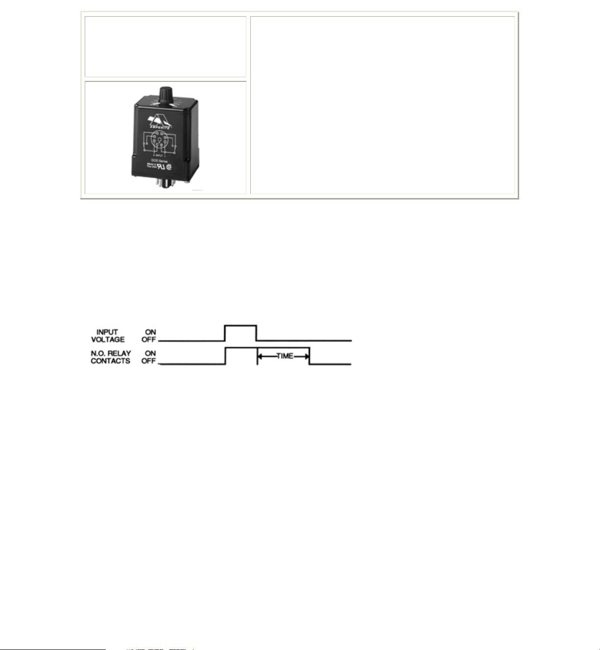
Timing Mode:
Upon the application of input voltage the relay immediately energizes. The timing cycle
begins when input voltage is removed. When the timing cycle is complete, the relay will
de-energize. The relay contacts will reset when input voltage is reapplied.
Timing Diagram:
… Solid state analog circuitry
… True delay on dropout: Timing cycle after
power removal
… DPDT (2 form C) isolated 4 ampere relay
contacts
… Timing selection: Knob adjustable or Fixed
… Numerous models timing from 0.1 secs. to 300
secs.
… UL File #E96739 (M)
… CSA File #LR62586
Contact Information:
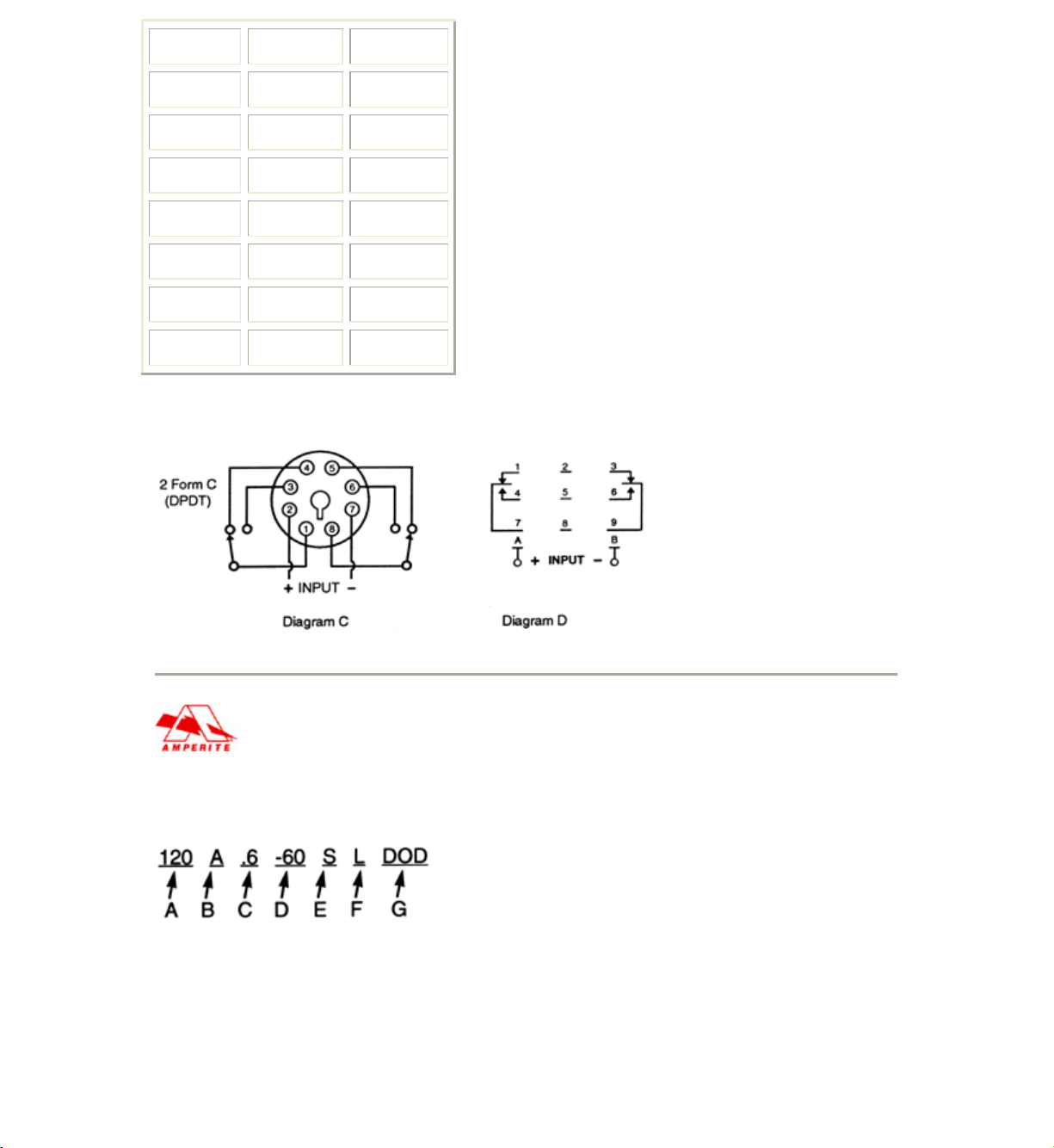
Arrangement: 2 form C (DPDT) - Diagrams C & D
Contact Material: Gold Clad Silver Alloy
Rating (Resistive):
Maximum Switching Power - 1000 VA, 90W
Maximum Switching Voltage - 250V AC, 48V DC
Maximum Switching Current - 4 Amperes
Nominal Switching Capacity - 4A 250V AC, 3A 30V DC
UL/CSA Ratings - 4A 1/20 HP 125, 250V AC, 3A 30V DC
Expected Life @ 25°C:
100 Million operations, Mechanical
Electrical: 100,000 operations at 4A 250V AC
200,000 operations at 3A 30V DC
Environmental Information:
Temperature Range: Ambient: -40°C to +65°C (-40°F to +149°F)
Page 2
Mechanical Information:
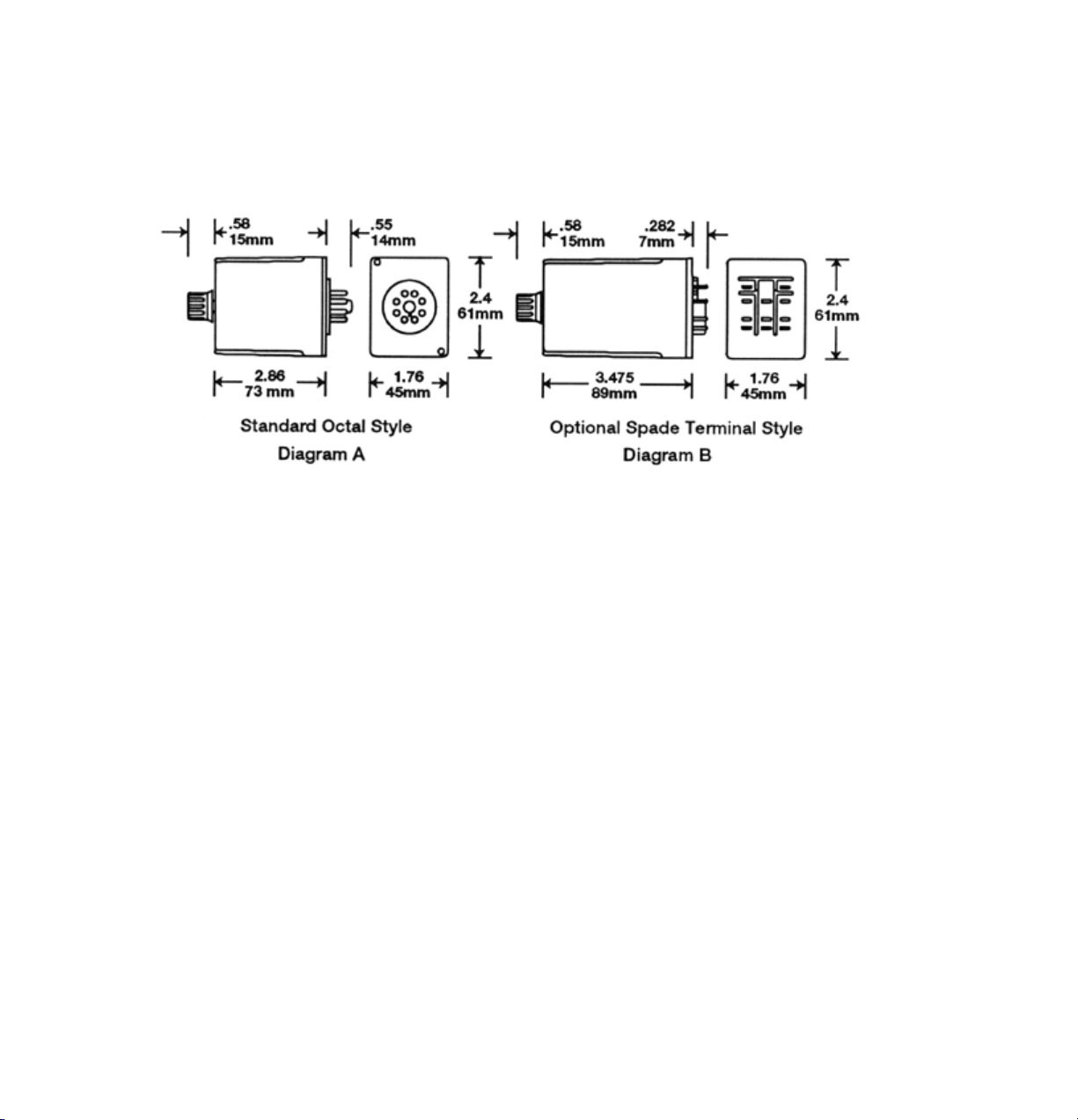
Termination: 8 pin Octal Style Plug or 11 pin spade terminals (Diagram C&D)
Enclosure: Black plastic case. Knob adjustable models have a dial scale for reference
only.
Weight: 4 oz (114g) approx.
Outline Dimensions:
Timing Specifications:
Timing - Fixed: 0.1 secs. through 300 secs.
Timing Ranges: Standard timing ranges are as follows:
.1 to 10 secs., .6 to 60 secs., 1.2 to 120 secs., 3 to 300 secs. Custom timing is available.
Timing Adjustment: Knob adjustable potentiometer.
Timing Tolerance: Fixed Units: ± 5%; Adjustable Units: -0 to +25% of maximum
specified delay time.
Minimum specified value or less at low end.
Repeatability: ± 5%.
Initial Dielectric Strength:
Between open contacts: 750V RMS,
Between adjacent contacts: 1000V RMS,
Between contacts & coil: 1500V RMS
Input Information:
Voltage: AC units- 12V, 24V, and 120V; DC units- 12V, 24V, 48V and 110V. Other
voltages are available.
Power Requirement: AC units: 2 VA or less; DC units: 2 Watts or less
Transient Protection: 1 JOULE MOV
Polarity Protection: On DC units - Yes
Input Voltages & Limits:
Page 3
Nominal Minimum Maximum
12V AC 10V 14V
24V AC 20V 28V
120V AC
105V 130V
12V DC 11V 14V
24V DC 20V 32V
48V DC 41V 55V
110V DC
95V 125V
Wiring Diagrams:
Ordering Information:
Definition of a part number for the Amperite DOD Series Time Delay Relay.
Example:
A: Denotes nominal input voltage. Voltages Available: 12, 24 & 120V AC; 12, 24, 48 &
110V DC. Custom Voltages are available.
B: Denotes type of input current required for operation:
Page 4

A = AC - Alternating Current
D = DC - Direct Current
C & D: Denotes range of knob adjustability for timing (in seconds or minutes) where:
C = Minimum time delay. D = Maximum time delay for adjustable TDR’S.
Note: 1.) Ranges available: See standard timing ranges above. Custom Timing is
available.
2.) Both values (C & D) can be replaced by a single value for a factory preset time delay
in seconds or minutes from 0.1 secs. through 300 secs.
E: Denotes use of seconds or minutes in timing value(s), S = seconds, M = minutes.
F: Enter "L" if optional 11-pin spade terminals are required (Diagrams B & D).
G: Denotes DPDT (2 form C) 4 amp delay on dropout DOD Series Time Delay Relay.
Solving Your Relay Requirements Since 1922
 Loading...