

Page 1
Owner’s Manual
Page 2

IMPORTANT SAFETY INSTRUCTIONS
Opto Comp Analog Optical Compressor
1. Read these instructions.
2. Keep these instructions.
3. Heed all warnings.
4. Follow all instructions.
5. Do not use this apparatus near water.
6. Clean only with a dry cloth.
7. Do not block any ventilation
openings. Install in accordance
with the manufacturer’s instructions.
8. Do not install near any heat sources
such as radiators, heat registers, stoves,
or other apparatus (including amplifiers)
that produce heat.
9. Do not defeat the safety purpose
of the polarized or grounding-type plug.
A polarized plug has two blades with one
wider than the other. A grounding-type
plug has two blades and a third grounding
prong. The wide blade or the third prong
are provided for your safety. If the provided
plug does not fit into your outlet, consult
an electrician for replacement of the
obsolete outlet.
10. Protect the power cord from being
walked on or pinched particularly at plugs,
convenience receptacles, and the point
where they exit from the apparatus.
11. Only use attachments/accessories
specified by the manufacturer.
12. Use only with a cart,
stand, tripod, bracket, or table
PORTABLE CART
WARNING
specified by the manufacturer,
or sold with the apparatus.
When a cart is used, use
caution when moving the cart/
apparatus combination to
avoid injury from tip-over.
13. Unplug this apparatus during lightning
storms or when unused for long periods
of time.
14. Refer all servicing to qualified service
personnel. Servicing is required when the
apparatus has been damaged in any way,
such as power-supply cord or plug is
damaged, liquid has been spilled or
objects have fallen into the apparatus,
the apparatus has been exposed to rain
or moisture, does not operate normally,
or has been dropped.
15. This apparatus shall not be exposed
to dripping or splashing, and no object
filled with liquids, such as vases or beer
glasses, shall be placed on the apparatus.
16. Do not overload wall outlets and
extension cords as this can result in
a risk of fire or electric shock.
17. The MAINS plug or an appliance
coupler is used as the disconnect device,
so the disconnect device shall remain
readily operable.
NOTE: This equipment has been tested and
found to comply with the limits for a Class
B digital device, pursuant to part 15 of
the FCC Rules. These limits are designed
to provide reasonable protection against
harmful interference in a residential
installation. This equipment generates,
uses, and can radiate radio frequency
energy and, if not installed and used
in accordance with the instructions,
may cause harmful interference to radio
communications. However, there is no
guarantee that interference will not occur
in a particular installation.
If this equipment does cause harmful
interference to radio or television reception,
which can be determined by turning
the equipment off and on, the user
is encouraged to try to correct the
interference by one or more of the following
measures:
• Reorient or relocate the receiving
antenna.
• Increase the separation between the
equipment and the receiver.
• Connect the equipment into an outlet
on a circuit different from that to
which the receiver is connected.
• Consult the dealer or an experienced
radio/TV technician for help.
CAUTION: Changes or modifications to this
device not expressly approved by Yamaha
Guitar Group, Inc. could void the user’s
authority to operate the equipment under
FCC rules.
This apparatus does not exceed the Class
A/Class B (whichever is applicable) limits
for radio noise emissions from digital
apparatus as set out in the radio
interference regulations of the Canadian
Department of Communications.
2
Page 3
Opto Comp Analog Optical Compressor
Exposure to extremely high noise levels
may cause permanent hearing loss.
Individuals vary considerably in
susceptibility to noise-induced hearing
loss, but nearly everyone will lose some
hearing if exposed to sufficiently intense
noise for a period of time. The U.S.
Government’s Occupational Safety and
Health Administration (OSHA) has specified
the permissible noise level exposures shown
in the following chart.
According to OSHA, any exposure in excess
of these permissible limits could result
in some hearing loss. To ensure against
potentially dangerous exposure to high
sound pressure levels, it is recommended
that all persons exposed to equipment
capable of producing high sound pressure
levels use hearing protectors while
the equipment is in operation. Ear plugs
or protectors in the ear canals or over
the ears must be worn when operating
the equipment in order to prevent
permanent hearing loss if exposure
is in excess of the limits set forth here:
Duration, per
day in hours
8 90 Duo in small club
6 92
4 95 Subway Train
3 97
2 100 Very loud classical music
1.5 102
1 105 Ryan screaming at Troy about deadlines
0.5 110
0.25 or less 115 Loudest parts at a rock concert
Sound Level
dBA, Slow
Response
Typical Example
RISK OF ELECTRIC SHOCK! DO NOT OPEN!
CAUTION: TO REDUCE THE RISK OF ELECTRIC SHOCK DO NOT
REMOVE COVER (OR BACK). NO USER-SERVICEABLE PARTS INSIDE.
REFER SERVICING TO QUALIFIED PERSONNEL.
The lightning flash with arrowhead symbol within
an equilateral triangle means “electric shock hazard”.
It is intended to alert the user to the presence of
uninsulated “dangerous” voltage within the product
enclosure, that may be of significant magnitude to
constitute a risk of electric shock to persons.
The exclamation point within an equilateral triangle means
“Warning/Caution!”. It is intended to alert the user of the
presence of important operating and maintaining (servicing)
instructions in the literature accompanying the appliance.
WARNING — To reduce the risk of fire or electric shock,
do not expose this apparatus to rain or moisture.
Laite on liitettävä suojakoskettimilla varustettuun pistorasiaan.
Apparatet må tilkoples jordet stikkontakt.
Apparaten skall anslutas till jordat uttag.
CAUTION
Correct disposal of this product: This symbol indicates that this product should not be disposed of with your household
waste, according to the WEEE directive (2012/19/EU) and your national law. This product should be handed over to an authorized
collection site for recycling waste electrical and electronic equipment (EEE). Improper handling of this type of waste could
have a possible negative impact on the environment and human health due to potentially hazardous substances that are generally
associated with EEE. At the same time, your cooperation in the correct disposal of this product will contribute to the effective
usage of natural resources. For more information about where you can drop off your waste equipment for recycling, please contact
your local city office, waste authority, or your household waste disposal service.
3
Page 4

Opto Comp Analog Optical Compressor
Table of Contents
Important Safety Instructions .................................................. 2-3
Table Of Contents ..................................................................... 4
Introduction.............................................................................. 4
Features ................................................................................... 4
Opto Comp Analog Optical Compressor Top Panel Features .......... 5
Opto Comp Analog Optical Comp Rear and Bottom Panel Features 6
Opto Comp Analog Optical Compressor Bottom Panel Features ..... 7
Opto Comp Analog Optical Compressor Suggested Settings ........... 8
Opto Comp Analog Optical Compressor Block Diagram ................. 9
Technical Specifications / Service Information ........................... 10
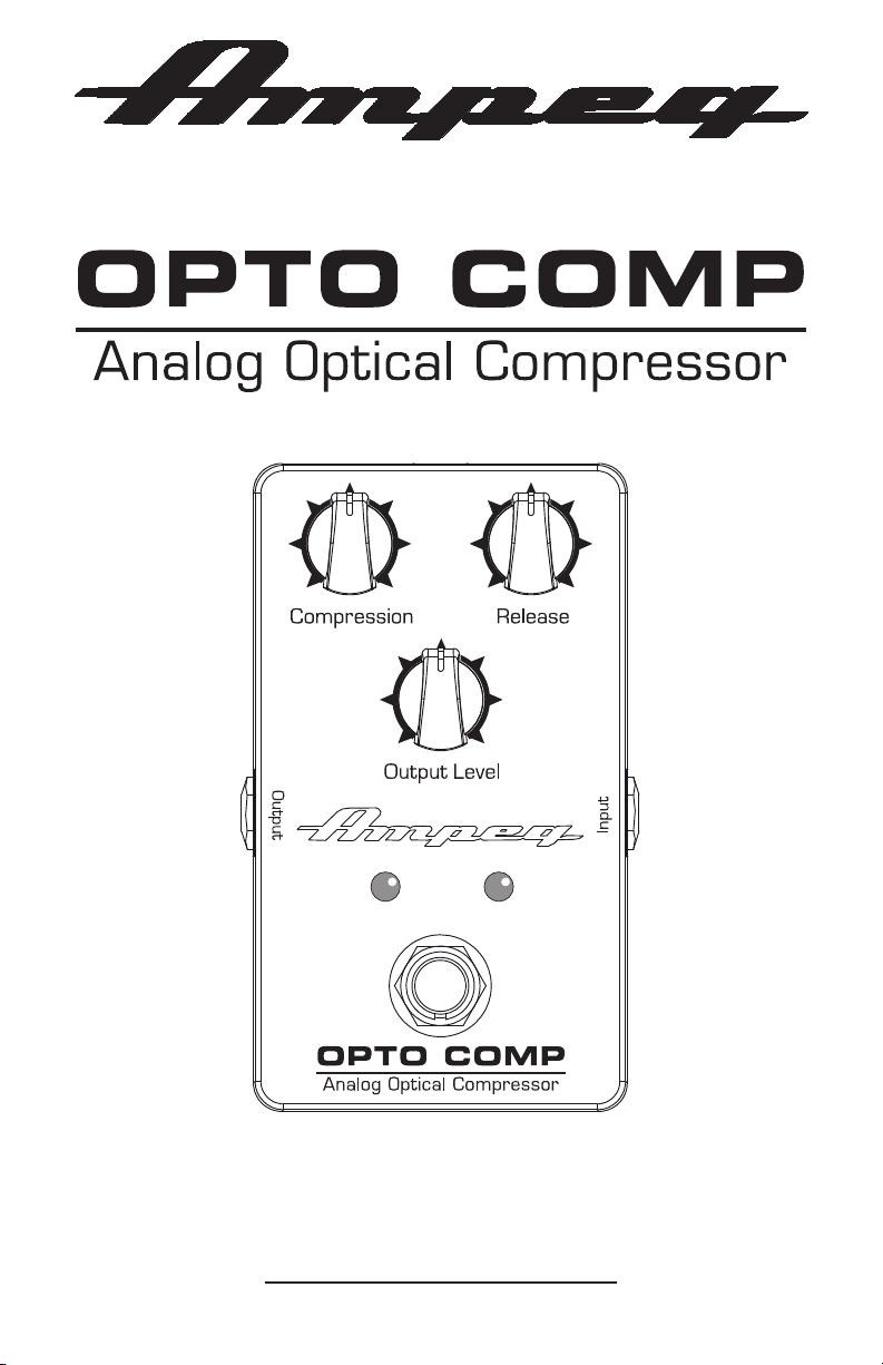
Introduction
The Ampeg Opto Comp Analog Optical Compressor pedal utilizes an optical circuit
to deliver smooth, vintage style compression to add headroom and sustain to your guitar
or bass.
Dial in a fast, subtle style to control peaks or crank up the compression to add
a unique character. Featuring a roadworthy all-metal chassis and true bypass switching,
the Opto Comp Analog Optical Compressor brings your tone to new heights.
Like all Ampeg products, your Opto Comp Analog Optical Compressor pedal
is designed by musicians and built using only the best of components. Each pedal
is tested to confirm that it meets our specifications, and we believe that this pedal
is the absolute best that it can be.
In order to get the most out of your new pedal, please read this manual before
you begin playing. Best of luck in all of your musical endeavors!
And thank you for choosing Ampeg.
Features:
• Delivers smooth, vintage style compression.
• Dial in the perfect sound with Compression and Release controls.
• Output control allows you to maximize sustain and make up for heavy compression.
• True bypass, analog design with incredible signal-to-noise ratio.
• Roadworthy all-metal chassis construction.
• 9V DC supply or battery capable (not included).
Like us
Follow us
Watch our dang videos
4
Page 5

Opto Comp Analog Optical Compressor
Opto Comp Analog Optical Compressor Top Panel Features
1. INPUT: The signal output from an
instrument (active or passive) may
be connected to this 1/4" input by
means of an unbalanced shielded
instrument cable.
NOTE: There is a –15 dB pad
jumper located inside of the pedal.
Details on switching the jumper
may be found on page 7.
NOTE: Unplug the input cable when
not in use, as the 9V battery will
drain (and eventually die). Details
on replacing the battery may be
found on page 7.
8
3
54
6
1
7
2
2. OPTO COMP ON/OFF SWITCH:
Engage this switch to activate
the Opto Comp pedal. This pedal
is true bypass meaning the signal
will pass through from input to
output with no circuitry in between
when the switch is disengaged.
3. ON/OFF LED: This LED illuminates
purple when the pedal is engaged.
4. COMPRESSION: A compressor
squeezes the dynamic range
of a signal, reducing the volume
of loud notes, which allows
the overall volume to be boosted.
It can really balance out very
dynamic playing styles. Using
a slight amount of compression
can beef up your tone a bit.
You can also get a “punchier”
sound using compression.
Rotate the compression knob –
also known as “ratio control” – to
adjust the overall amount of
compression applied to a signal.
The ratio ranges from a minimum
of 1:1 (fully counter-clockwise)
to a maximum of 10:1 (fully
clockwise), landing at 3:1
at the center position.
Analog Optical Compressor
5. RELEASE: The release knob may
also be thought of as a “time
control” knob, as it determines
how long it takes for the
compressor to end gain reduction.
The release time ranges from
a minimum of 75 milliseconds
(fully counter-clockwise) to
a maximum of 600 milliseconds
(fully clockwise).
6. OUTPUT LEVEL: Rotate this knob
to control the overall output level
from mute (fully counter-clockwise)
to +14 dB (fully clockwise).
Use it wisely, and turn it down
when making connections or trying
something new.
NOTE: The output level control
is active only when the pedal
is engaged.
7. GAIN REDUCTION LED: This green
LED increases in brightness
as gain reduction increases.
5
Page 6

Opto Comp Analog Optical Compressor
Opto Comp Analog Optical Compressor Rear and Bottom Panel Features
8. OUTPUT: Typically, this 1/4" output
jack connects to the input of
an external power amplifier – or
powered loudspeakers, as long as
they have their own input controls
to adjust the volume level – by
means of an unbalanced shielded
instrument cable.
However, it may be connected
to an external mixer, recorder,
or interface. In this way, you
do not have to mic the speaker
cabinet in order to add it to the
main mix, or to record. The level
of the signal is affected by the
volume control.
9. POWER CONNECTOR: This is where
to connect the optional power
supply.
Before plugging in the power
supply, make sure that you are
using the correct one for your
country (see below).
NOTE: A power supply may be
purchased through your favorite Ampeg
Dealer. Be sure to ask for part number:
2045758-00: United States
2045758-01: Europe
2045758-02: Japan
2045758-03: United Kingdom
2045758-04: Australia
2045758-05: China
2045758-06: Brazil
BOTTOM PANEL ACCESS
A –15 dB pad jumper is located
inside the bottom of the pedal.
This is also where the 9V battery
is housed.
Removing the bottom is easy.
Simply start by placing the pedal
top down on a soft, dry cloth.
Remove each of the four screws
by turning them counter-clockwise.
Be sure to keep them in a safe
place as you will need them again!
9
6
Page 7

Opto Comp Analog Optical Compressor
Opto Comp Analog Optical Compressor Bottom Panel Features
10. 9V BATTERY
The Opto Comp pedal may
be powered by 9V battery instead
of using a power supply. As seen
in the illustration below, it tucks in
nicely inside a compartment of the
circuit board next to the edge of
the pedal.
NOTE: Unplug the input cable when
not in use, as the 9V battery will
drain (and eventually die).
NOTE: When replacing the
bottom of the pedal, line up
the rectangular foam piece over
the battery. Turn the screws
clockwise to affix to the bottom
to the pedal.
10
123
J1
PINS 1-2: NORMAL
PINS 2-3: 15dB PAD
Ok, ok...there could be no jumper,
but that just sets the pedal to its
normal/default [pins 1-2] setting
(with about 1/2 dB loss).
Referencing the diagram to the
left, slide the jumper out then
back in on the pins that you want
to use for your instrument. Fingers
should work just fine, but it’s ok to
use needle-nose pliers to remove
the jumper, if necessary.
NOTE: When replacing the
bottom of the pedal, line up
the rectangular foam piece
over the battery. Turn the screws
clockwise to affix to the bottom
to the pedal.
NOTE: If you are experiencing
excessive distortion – distortion
begins at approximately 1.5 Vrms –
then you might want to utilize the
15 dB pad by moving the jumper
to pins 2-3.
11
11. –15 dB PAD JUMPER
Moving the –15 dB pad jumper
reduces the input signal by
15 dB and compensates for
higher output instruments.
This attenuation is suited for
use with basses that have active
electronics or high-output pickups.
There are only two possibilities.
The jumper can be on:
Pins 1-2 [Normal – default] or
Pins 2-3 [15 dB pad]
7
Page 8

Opto Comp Analog Optical Compressor
Opto Comp Analog Optical Compressor Suggested Settings
* Output Level to taste
Easy Compression
Totally Squished
Fretless
Slap Happy
8
Page 9

Opto Comp Analog Optical Compressor
Opto Comp Analog Optical Compressor Block Diagram
OUTPUTINPUT
GAIN
CONTROL
OUTPUT LEVEL
OPTO
TIME
RELEASE
CONTROL
RATIO
CONTROL
COMPRESSION
LEVEL
AC-TO-DC
DETECTOR
ISOLATOR
HI-Z
INPUT
SIGNAL
JFET
BUFFER
PAD
(O dB / –15 dB)
GAIN
AMPLIFIER
REDUCTION
HEAVY-DUTY
FOOTSWITCH
TRUE-BYPASS SWITCHING PATH
9
Page 10

Opto Comp Analog Optical Compressor
OPTO COMP ANALOG OPTICAL COMPRESSOR TECH SPECS
Signal-to-Noise Ratio 80 dB
(100 Hz @ 1.00 Vrms)
Maximum Gain +14 dB
Controls
Compression Ratio, dB (I/O) Minimum: 1:1
Maximum: 10:1
Release Time Minimum: 75 milliseconds
Maximum: 600 milliseconds
Output Level Gain Mute to +14 dB
Impedances Input 1 M @ NORMAL,
166 k w/–15 dB PAD
Output 200
Power Requirements Internal: 9 V Battery
External: 9 VDC, ≥25 mA
Size (H x W x D) 2.2 in x 2.6 in x 4.5 in
56 mm x 66 mm x 114 mm
Weight 0.6 lb / 0.3 kg (approximately)
All specifications subject to change
Service Information
If you are having a problem with your Opto Comp Analog Optical Compressor, you
can go to our website (www.ampeg.com) and click on Support for service information,
or call Technical Support at 1-818-575-3600 Monday-Friday during normal business
hours, Pacific Time, to receive assistance. If you are outside of the U.S., contact your
local distributor for technical support and service.
The Opto Comp Analog Optical Compressor is housed in a corrosion resistant die-cast zinc chassis,
so be sure to clean it with a dry lint-free cloth. Never spray cleaning agents on the Opto Comp Analog
Optical Compressor. Avoid abrasive cleansers which would damage the finish.
Ampeg continually develops new products and improves upon existing ones. For this reason, the specifications
and information in this manual are subject to change without notice.
“Ampeg” is a registered trademark of Yamaha Guitar Group, Inc. All other brand names mentioned are trademarks or
registered trademarks of their respective holders and are hereby acknowledged.
www.ampeg.com
©2018 Yamaha Guitar Group Inc.
26580 Agoura Road • Calabasas, CA 91302-1921
10
Part No. SW1230 Rev. B 07/18
Page 11

Owner’s Manual
 Loading...