

Page 1
MICRO-CL Stack
Owner’s Manual
Page 2

MICRO-CL Stack
TABLE OF CONTENTS
What’s in the Box . . . . . . . . . . . . . . . . . . . . . . . . . . . . . . . . . . . . . . . . . . . . . . . 2
Introduction . . . . . . . . . . . . . . . . . . . . . . . . . . . . . . . . . . . . . . . . . . . . . . . . . . . . 2
Features . . . . . . . . . . . . . . . . . . . . . . . . . . . . . . . . . . . . . . . . . . . . . . . . . . . . . . . 3
The Front Panel . . . . . . . . . . . . . . . . . . . . . . . . . . . . . . . . . . . . . . . . . . . . . . . . . 4
The Rear Panel . . . . . . . . . . . . . . . . . . . . . . . . . . . . . . . . . . . . . . . . . . . . . . . . . 5
Rear Panel Connector Plate . . . . . . . . . . . . . . . . . . . . . . . . . . . . . . . . . . . . . . .5
System Block Diagrams . . . . . . . . . . . . . . . . . . . . . . . . . . . . . . . . . . . . . . . . . . 6
Technical Specications . . . . . . . . . . . . . . . . . . . . . . . . . . . . . . . . . . . . . . . . . . 7
Warranty and Support . . . . . . . . . . . . . . . . . . . . . . . . . . . . . . . . . . . . . . . . . . . . 8
What’s in the Box
MICRO-CL Amplier and Speaker Cabinet, Speaker Cable, Power Cable, Quick Start
Guide.
Introduction
Let’s face it. You are the type who would happily crank up a full Ampeg SVT® stack in
your living room. Heck, who needs neighbors, anyway? And noise violations are really
just a badge of honor, right? For the rest of us, there is the Ampeg MICRO-CL Stack,
delivering 100 watts of Ampeg tone into any situation. It’s perfect for those just getting
into Ampeg tone or for the seasoned bassist looking to practice in far ung locations, like
the master bathroom. The MICRO-CL Stack features a tough, 2x10" cab and tools like
stereo input and output for silent practice, eects loop, and direct out for recording. It’s
everything you want in a full stack, micro-sized to t perfectly into your life.
Like all Ampeg products, the MICRO-CL Stack was designed by musicians and built
using only the best of components. Each stack is tested to conrm that it meets our
specications, and we believe that this product is the absolute best that it can be.
In order to get the most out of your MICRO-CL Stack, please fully read this Owner’s
Manual, as well as the Important Safety Instructions included with the product, before
playing.
Best of luck in all of your musical endeavors!
Sincerely,
The dedicated team at Ampeg
2
Page 3

Features
Amplier:
• Power output: 100 Watts at 8 Ω
• Preamp: Solid-state
• Power Amp: Solid-state
• Tone Controls: Bass, Mid, Treble
• Unbalanced Line Out
• Eects Loop
• Dual Inputs (0 dB and –15 dB)
• 1/8" Headphone Out / Line In
• Dimensions (H x W x D): 7" x 12.2" x 10"
• Handling Weight: 13.8 lb / 6.3 kg
Speaker Cabinet:
• 100 Watts Power Handling at 8 Ω
• 2 x 10" LF Drivers
• Frequency Response: 57 Hz – 5 kHz
• Sensitivity: 100 dB SPL @ 1W/1m
• Dimensions (H x W x D): 13" x 24" x 11"
• Handling Weight: 33.2 lb / 15.1 kg
MICRO-CL Stack
3
Page 4
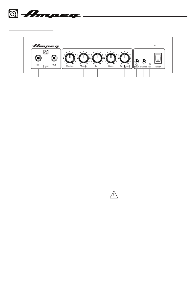
The Front Panel
1 2 3 4 5 6 7 8 9 10 11
MICRO-CL Stack
MICRO CL
-15dB0dB
TrebleMasterInput Mid Bass Aux Level
1. 0 dB INPUT: The signal output from a
passive instrument may be connected
to this 1/4" Input by means of a
shielded instrument cable.
2. –15 dB INPUT: The signal output from
an active instrument may be connected
to this 1/4" input by means of a
shielded instrument cable.
3. MASTER: Use to control the
output level of the instrument only.
It aects the Speaker Output [13]
and Headphones Output [9]. Use it
wisely and turn it down when making
connections, putting on headphones, or
trying something new.
4. TREBLE: Use to adjust the high
frequency level of the amplier. This
provides up to 13 dB of boost, or 13 dB
of cut, at 6 kHz. The high frequency
output is at at the center position.
5. MID: Use to adjust the midrange
frequency level of the amplier. This
provides up to 11 dB of boost, or
11 dB of cut, at 600 Hz. The midrange
frequency output is at at the center
position. Rotate the control counterclockwise for a “contoured” sound
(more distant, less midrange output) or
clockwise for a sound that really cuts
through.
6. BASS: Use to adjust the low frequency
level of the amplier. This provides up
to 11 dB of boost, or 11 dB of cut, at
50 Hz. The low frequency output is at
at the center position.
Aux
Input
PowerPhones
On
7. AUX LEVEL: Use to control the output
level of the signal fed to the Aux Input
[8]. Use it wisely and turn it down
when making connections, putting on
headphones, or trying something new.
8. AUX INPUT: The audio output from line
level sources such as a mobile device
or MP3 player, can connect to this 1/8"
TRS stereo input. The incoming audio is
mixed with the preamp signals, so you
can play along to a practice track while
listening with headphones. (The audio
here appears in the cabinet speakers
until headphones are plugged in; then
heard in the headphones only).
9. PHONES: Use this 1/8" TRS stereo
output to connect headphones. The
output here is a mix of the line level
signals reaching the amplier, plus any
incoming audio from the Aux In jack [8].
Before putting on headphones,
make sure the Master control [3]
and Aux Level [7] are turned down.
This will reduce the chance of hearing
damage due to loud volumes.
Note: The speaker is muted when
headphones are plugged in.
10. ON LED: This LED illuminates red when
the power is on.
11. POWER SWITCH: Use this switch to
turn the overall system power on or o.
Press the top of the switch to turn on
the power, and press the bottom of the
switch to turn it o.
4
Page 5
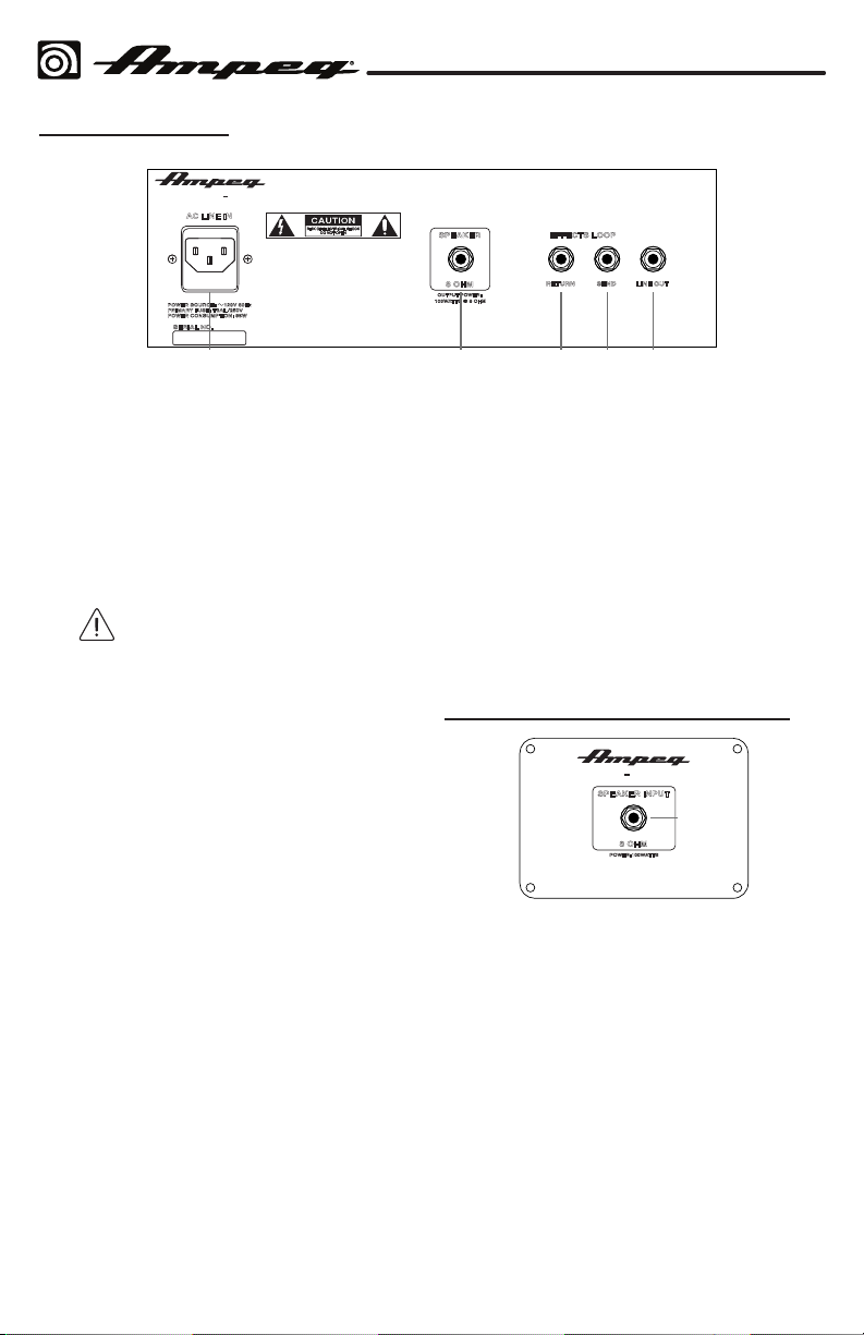
The Rear Panel
12 13 14 15 16
MICRO CL
AC LINE IN
POWER SOURCE: 120V 60Hz
PRIMARY FUSE: T3AL/250V
POWER CONSUMPTION: 85W
SERIAL NO.
CAUTION: TO PREVENT ELECTRIC SHOCK DO NOT REMOVE
CHASSIS (OR BACK). NO USER SERVICEABLE PARTS INSIDE. REFER
SERVICING TO QUALIFIED SERVICE PERSONNEL.
AVIS: RISQUE DE CHOC ELECTRIQUE- NES PAS OUVRIR.
WARNING: TO REDUCE THE RISK OF FIRE OR ELECTRIC SHOCK DO
NOT EXPOSE THIS APPLIANCE TO RAIN OR MOISTURE.
ATTENTION: UTILISER UN FUSIBLE DE RECHANGE DE MEME TYPE.
SPEAKER EFFECTS LOOP
8 OHM
OUTPUT POWER:
100WATTS @ 8 OHM
RETURN SEND LINE OUT
MICRO-CL Stack
12. AC POWER INPUT: The amplier is
equipped with a detachable power
cable that plugs into this IEC Mains
socket on the back of the amplier. The
AC power cord should only be plugged
into a grounded power outlet that
meets all applicable electrical codes
and is compatible with the voltage,
power, and frequency requirements
stated on the rear panel of the amplier.
Do not attempt to defeat the
safety ground connection.
13. SPEAKER OUTPUT JACK: This 1/4"
TS Output jack supplies speaker-level
power to the Speaker Cabinet Input
[17]. The rated power output is 100
Watts into 8 Ω.
Use a (non-shielded) speaker cable
with 1/4" TS ends to make the
connections. Do not use (shielded)
instrument cables as they may
overheat.
14. EFFECTS LOOP RETURN JACK: Use
this 1/4" TS unbalanced input to return
the processed, line level output of an
external eects processor (for example).
The processor could be fed by signals
from the Eects Loop Send [15].
15. EFFECTS LOOP SEND JACK: Use this
1/4" TS unbalanced output to send a
line level output to an external eects
processor (for example). The output
here is aected by all controls, including
the Master [3].
Use the Eects Loop Return jack [14]
to feed the returned processed signals
back into the power amplier.
16. UNBALANCED LINE OUT JACK:
Typically, you would connect this
Output to the balanced input of an
external mixer or a recorder. In this way,
you do not have to mic the speaker
cabinet in order to add it to the main
mix or to record. This output is not
aected by the Master control [3].
This output can connect to external
power ampliers, or powered
loudspeakers, as long as they have
their own input controls to adjust the
volume level.
Rear Panel Connector Plate
MC 210E
SPEAKER INPUT
17
8 OHM
POWER:100WATTS
17. 1/4" TS INPUT JACK: Connect the
speaker-level output [13] to this speaker
input jack using a (non-shielded)
speaker cable.
Always use a (non-shielded) speaker
cable—never use a (shielded)
instrument cable to connect speakers
to an amplier.
5
Page 6

System Block Diagrams
Amplifier
Cabinet
Amplier:
MICRO-CL Stack
Inputs
0 dB
-15 dB
AUX
Inputs
Phones
Speaker Cabinet:
TONE CONTROL CIRCUITRY
Treble
Aux Level
Input
Mid
Bass
POWER
AMPLIFIER
100 W
(2) 10" speakers
Volume
MUTE
LINE
OUT
Send
EFFECTS
LOOP
Return
SPEAKER
OUTPUT
6
Page 7
MICRO-CL Stack
Technical Specications
Output Power Rating 100 Watts @ 8 Ω
Signal to Noise Ratio 72 dB (20 Hz – 20 kHz, unweighted)
Maximum Gain 59 dB at 1 kHz
Amplier Inputs 2 x 1/4" Jacks [0dB, –15dB]
2 x 1/8" Jacks [Aux, Headphones]
Tone Controls Bass: +11/–11 dB @ 50 Hz
Midrange: +11/–11 dB @ 600 Hz
Treble: +13/–13 dB @ 6 kHz
Power Requirements Japan: 100V ~50–60 Hz, 85W
U.S.: 120V ~60 Hz, 85W
EU: 220–240V ~50–60 Hz, 85W
Amplier Size (H x W x D) 7 in/178 mm (with feet) x 12.2 in/310 mm
x 10 in/254 mm
Amplier Weight 13.8 lb / 6.3 kg
Cabinet Frequency Response 57 Hz – 5 kHz
Cabinet Sensitivity 100 dB SPL @ 1W/1m
Cabinet Input 1 x 1/4" Jack
Speaker Specs 2 x 10" LF drivers
Cabinet Size (H x W x D) 13 in/330 mm (with feet) x 24 in/610 mm
x 11 in/279 mm
Cabinet Weight 33.2 lb / 15.1 kg
The MICRO-CL is covered with a durable, fabric-backed vinyl material. Clean with a dry, lint-free cloth. Never spray
cleaning agents onto the stack. Avoid abrasive cleansers which would damage the finish.
Ampeg continually develops new products and improves upon existing ones. For this reason, the specifications
and information in this manual are subject to change without notice.
7
Page 8

MICRO-CL Stack
Warranty and Support
Visit WWW.AMPEG.COM to...
(1) ...identify WARRANTY coverage provided in your local market. Please keep your
sales receipt in a safe place.
(2) ...REGISTER your product.
(3) ...CONTACT Technical Support, or call 818-575-3600.
www.ampeg.com
26580 Agoura Road, Calabasas, CA 91302-1921 USA
© 2019 Yamaha Guitar Group, Inc. All rights reserved.
Ampeg, the Ampeg logo, and SVT are trademarks or registered trademarks of Yamaha Guitar Group, Inc. in the U.S.
and/or other jurisdictions.
Yamaha Guitar Group, Inc.
Rev. A
8
 Loading...