

Page 1

50th Anniversary SVT
Owner's Manual
Page 2

Heritage 50th Anniversary SVT
Bass Guitar Amplifier
TABLE OF CONTENTS
What’s in the Box . . . . . . . . . . . . . . . . . . . . . . . . . . . . . . . . . . . . . . . . . . . . . . . . . . . . 2
Introduction . . . . . . . . . . . . . . . . . . . . . . . . . . . . . . . . . . . . . . . . . . . . . . . . . . . . . . . . . 2
Key Features . . . . . . . . . . . . . . . . . . . . . . . . . . . . . . . . . . . . . . . . . . . . . . . . . . . . . . . . 3
Front Panel . . . . . . . . . . . . . . . . . . . . . . . . . . . . . . . . . . . . . . . . . . . . . . . . . . . . . . . . . 4
Rear Panel . . . . . . . . . . . . . . . . . . . . . . . . . . . . . . . . . . . . . . . . . . . . . . . . . . . . . . . . . . 6
Channel Voicings and Channel Jumping . . . . . . . . . . . . . . . . . . . . . . . . . . . . . . . . . . 8
Important Information About Tubes . . . . . . . . . . . . . . . . . . . . . . . . . . . . . . . . . . . . . . 8
Survival Tips for Tube Amplifiers . . . . . . . . . . . . . . . . . . . . . . . . . . . . . . . . . . . . . . . . 10
Changing the Tubes . . . . . . . . . . . . . . . . . . . . . . . . . . . . . . . . . . . . . . . . . . . . . . . . . 11
Setting Tube Bias and Balance . . . . . . . . . . . . . . . . . . . . . . . . . . . . . . . . . . . . . . . . . 12
Troubleshooting . . . . . . . . . . . . . . . . . . . . . . . . . . . . . . . . . . . . . . . . . . . . . . . . . . . . . 12
Block Diagram . . . . . . . . . . . . . . . . . . . . . . . . . . . . . . . . . . . . . . . . . . . . . . . . . . . . . . 13
Technical Specifications . . . . . . . . . . . . . . . . . . . . . . . . . . . . . . . . . . . . . . . . . . . . . . 14
Warranty and Support . . . . . . . . . . . . . . . . . . . . . . . . . . . . . . . . . . . . . . . . . . . . . . . . 15
What’s in the Box
Heritage™ 50th Anniversary SVT® Amplifier, Power Cable, Quick Start Guide.
Introduction
Congratulations, and welcome to the world of Ampeg! Whether this is your first experience with
Ampeg, or you’re a well-seasoned player who’s been around the globe a few times with our gear,
you are taking part in a piece of musical history. From here on out, nothing else will sound the
same... everything else will pale in comparison. You are one of the lucky few to take part in a new
chapter of an American legacy. Ampeg has come home! Each Heritage Series amplifier and cabinet
is designed and assembled right here in the U.S.A. We’ve heard from our bass players around
the globe about their dedication and commitment to Ampeg, and the Heritage Series is made
specifically for these players. It's just our way of saying thank you and letting you know that we
heard you loud and clear.
Ampeg is the standard by which all others are measured. We’ve been pounding bass players'
chests and audiences' booties for over 60 years now, and we’re not going to slow down any time
soon. From our early days of building “amplified pegs” for upright players, to building the world
famous, stadium-rattling SVT, Ampeg has been the choice for bassists—from touring professionals
to weekend warriors, and everyone in between. We were the first ones on the block listening and
building gear for bass players. Heck, even our company’s founding fathers were working, gigging
players. When they weren’t tinkering around the shop on new ideas, they were out in the clubs of
New York, earning their living. Not much has changed since then.
The average length of a hit song is 3 minutes and 40 seconds. We have been a part of most of
those hits for over 60 years. Now that you own a piece of Ampeg history, we want to be part of
your next hit.
Best of luck in all of your musical endeavors!
Sincerely,
The dedicated team at Ampeg
2
Page 3

Heritage 50th Anniversary SVT
Key Features
• 300W of all tube power
• Designed and hand assembled in the U.S.A.
• Etched front panel reminiscent of the original Ampeg 1969 “Blue Line” SVT
• Two discrete, independently voiced channels (1969 + 1975)
• Channel jumping between Channel One & Channel Two
• Never-seen-before front panel layout
• Vintage logo styled cup handles
• 50th Anniversary Heritage badge on rear panel
• Neutrik® speakON® outs
• Newly enhanced Transformer Balanced Output
• Ampeg Super Valve™ 6550 power tubes
Bass Guitar Amplifier
3
Page 4
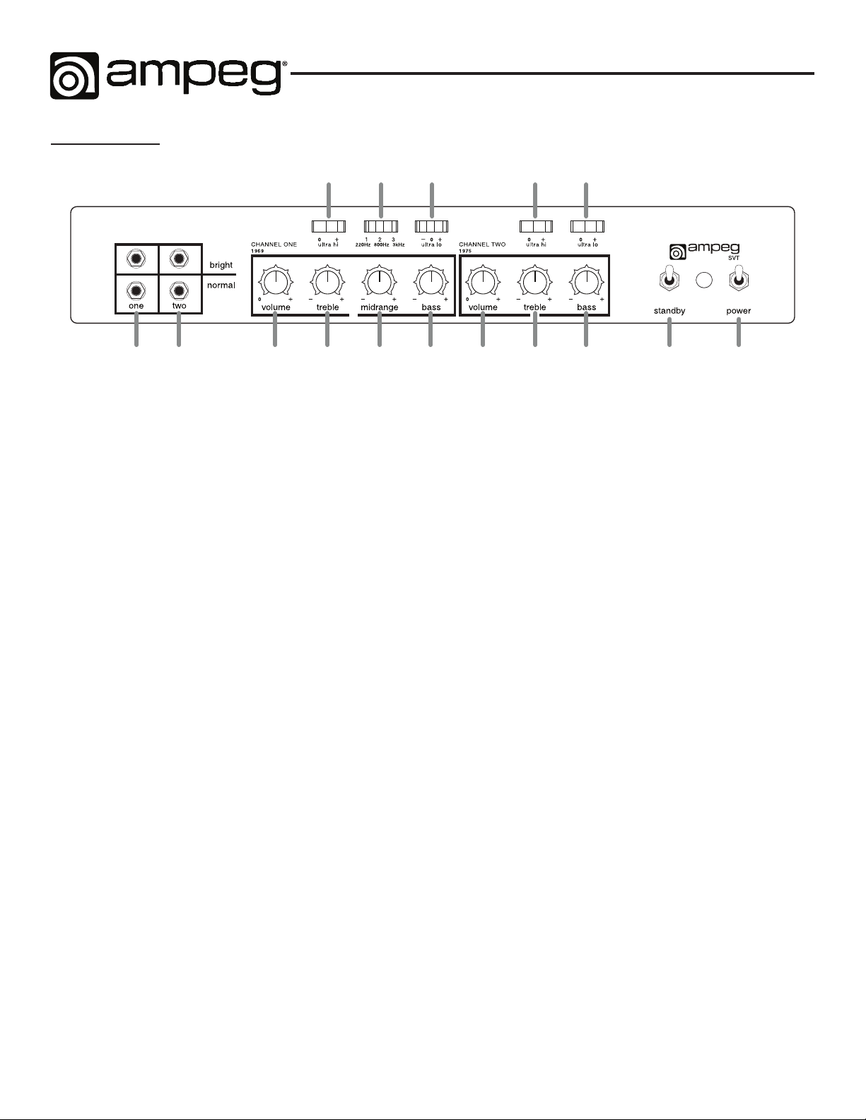
Front Panel
Heritage 50th Anniversary SVT
Bass Guitar Amplifier
87
1 2 3 4 5 6 10 11 12 15 16
1. CHANNEL ONE: (The Channel One 1969 Input jacks): The signal output from an instrument or
a line level signal may be connected to this 1/4" input by means of a shielded instrument cable.
Either the Bright or Normal jack may be used. The Bright jack enhances the high frequencies of
the input signal. The signal at these jacks is sent into the Channel One preamp section (Volume
and EQ controls). This channel is voiced like the revered, original 1969 “Blue Line” SVT.
2. CHANNEL TWO: (The Channel Two 1975 Input jacks): The signal output from an instrument or
a line level signal may be connected to this 1/4" input by means of a shielded instrument cable.
Either the Bright or Normal jack may be used. The Bright jack enhances the high frequencies of
the input signal. The signal at these jacks is sent into the Channel Two preamp section (Volume
and EQ controls). This channel is voiced like the iconic, 70's Magnavox® era “Black Line” SVT.
9
13 14
3. VOLUME: Use to adjust the output level of Channel One.
4. TREBLE: Use to adjust the high frequency level of Channel One. This provides up to 12 dB of
boost, or 12 dB of cut, at 4 kHz. The high frequency output is flat at the center position.
5. MIDRANGE: Use to adjust the midrange frequency level of Channel One. This provides up to 20
dB of boost, or 20 dB of cut, at the selected frequency (see #8 below). The midrange frequency
output is flat at the center position. Rotate the control counter-clockwise for a “contoured” sound
(more distant, less midrange output), or clockwise for a sound that really cuts through.
6. BASS: Use to adjust the low frequency level of Channel One. This provides up to 12 dB of boost,
or 12 dB of cut, at 40 Hz. The low frequency output is flat at the center position.
7. ULTRA HI: This switch, when engaged (right side down), enhances the amount of high frequency
output of Channel One. The amount of boost is dependent on the setting of the Volume control
(see #3 above).
8. MIDRANGE FREQUENCY (1•2•3): This switch selects the frequency that is affected by the
Midrange control (see #5). The available frequencies are 220 Hz (left side of the switch engaged),
800 Hz (switch in the center position), or 3 kHz (right side of the switch engaged).
9. BASS-CUT/OFF/ULTRA-LO: Engaging the left side of this switch decreases the low frequency
output of Channel One. Engaging the right side of this switch enhances the low frequency output
of Channel One. The switch is inactive in the center position.
4
Page 5
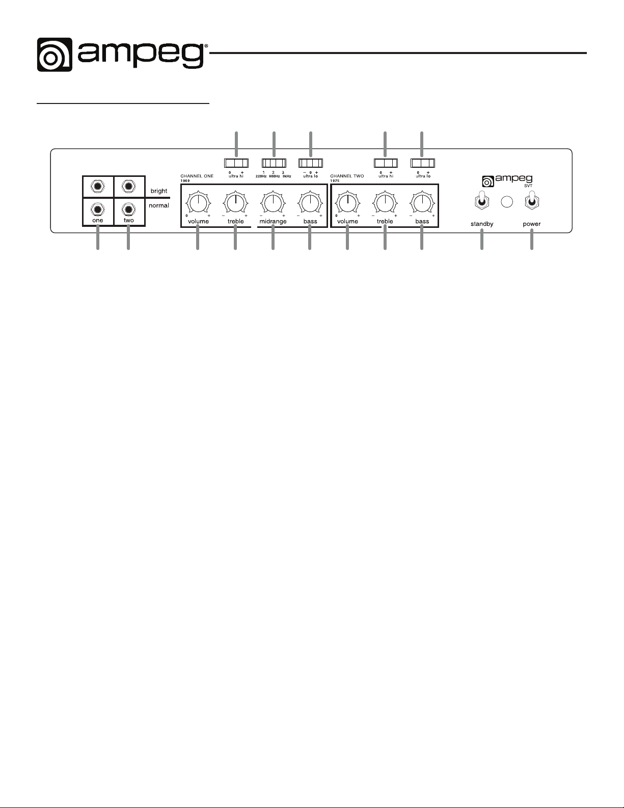
Front Panel - continued...
Heritage 50th Anniversary SVT
Bass Guitar Amplifier
87
1 2 3 4 5 6 10 11 12 15 16
10. VOLUME: Use to adjust the output level of Channel Two.
11. TREBLE: Use to adjust the high frequency level of Channel Two. This provides up to 12 dB of
boost, or 12 dB of cut, at 4 kHz. The high frequency output is flat at the center position.
12. BASS: Use to adjust the low frequency level of Channel Two. This provides up to 12 dB of boost,
or 12 dB of cut, at 40 Hz. The low frequency output is flat at the center position.
13. ULTRA-HI: This switch, when engaged (right side down), enhances the amount of high frequency
output of Channel Two. The amount of boost is dependent on the setting of the Volume control
(see #10).
14. ULTRA LO: This switch, when engaged (right side down), enhances the low frequency output of
Channel Two.
9
13 14
15. STANDBY SWITCH: Before powering the amplifier on, it is recommended to place the Standby
switch in the “down” position to place the amp in Standby mode. The Standby mode allows
the tubes to warm up, or remain warm, without high voltage being applied to them, helping to
extend tube life. Allow the amp to warm up for at least 10 seconds, then toggle the Standby
switch to the “up” position to put the amp into full operation. During short periods of non-use, it
is recommended to keep the amp powered on and in Standby mode.
16. POWER SWITCH: Use this switch to turn the overall system power on or off. (As mentioned in
item #15 above, it is recommended to place the Standby switch in the "down" position before
powering the amplifier on.) Flick the Power switch up to turn on the power to the amp. The Power
switch must be turned off to reset the amp after a Fault Condition. The adjacent lamp illuminates
green when the amplifier is powered on and is not in Standby mode.
NOTE:Alwaysbesuretheamplifierisconnectedtoeithera2Ωor4Ωspeakerloadbefore
turning the Power on, and before toggling the Standby switch to its "up" position (to disengage
Standby mode).
5
Page 6

Heritage 50th Anniversary SVT
Bass Guitar Amplifier
Rear Panel
292827262524 23222120191817
17. IEC POWER INPUT CONNECTOR: This is where you connect the supplied AC power cord. Plug
the male end of the cord into a grounded AC outlet. DO NOT DEFEAT THE GROUND PRONG
OF THE AC PLUG!
18. POLARITY: Place this switch in the position that provides the least audible buzz from the unit.
19. FUSE: This protects the unit from damage due to overload conditions or power line surges. If the
fuse blows, replace it only with the same size and type.
20. BIAS / BALANCE SECTION: These controls and sets of LEDs allow the user to properly bias the
power amp. See "Setting Tube Bias and Balance" on page 12 for a complete description of
how to use this section.
21. SLAVE OUT: The Slave Output is for slaving two amps together: it connects both their power
amps and their preamps.
22. POWER AMP IN: This jack connects directly to the internal power amp, for use with an external
preamp. When using an external preamp source, connect the OUTPUT of the source to this
jack using a shielded instrument cable to feed the source signal into the amplifier's power amp
section. The internal preamp is disconnected when a plug is inserted into this jack.
23. PREAMP OUT: This jack is a direct, post-master, preamp output, for use with an external power
amp. Connect this Preamp Out to an external power amp’s input jack using a shielded instrument
cable.
24. LEVEL: Use this control to adjust the signal level at the Transformer Bal Out jack (see #27). This
control works independently from the front panel Volume controls (#3 and #10).
25. PRE / POST: The signal at the Transformer Bal Out jack (#27) can be set to either Pre-EQ or PostEQ with this switch. With the switch in the OUT position, the signal at the jack is Pre-EQ. This is
a direct output, taken from the first preamp tube stage, and is not affected by the front panel EQ
controls. With the switch in the IN position, the signal is Post-EQ, and is controlled and modified
by the front panel Volume and EQ controls.
26. LIFT / GND: When this switch is engaged, it connects the ground connection at the Transformer
Bal Out jack (#27). This may help reduce residual hum and buzz sometimes picked up in line out
signal cables.
27. TRANSFORMER BAL OUT: This signal from this balanced output may be used to feed an
external power amplifier, mixing console, or house PA system. The signal level at this jack is
controlled by the Level control (#24) and may be Pre–EQ or Post–EQ, depending on the setting
of the Pre / Post switch (#25). Additionally, the Lift / Gnd switch (#26) is available to reduce any
noise that may occur at the Transformer Bal Out.
6
Page 7

Heritage 50th Anniversary SVT
Bass Guitar Amplifier
Rear Panel - continued...
292827262524 23222120191817
28. IMPEDANCE SELECTOR: Use this switch to match the output impedance of the amp to the
connected speaker(s) in use (2 or 4 ohms). For help in deciding the total impedance of your
system, consult the table below.
Cabinet
Impedance
2Ω 1 2Ω
4Ω 1 4Ω
4Ω 2 2Ω
8Ω 2 4Ω
8Ω 4 2Ω
29. SPEAKER OUTPUTS: Two 1/4" output jacks and one speakON output jack supply speakerlevel power to the cabinet. The rated power output is 300 Watts RMS into 2 or 4 ohms. All
three outputs are wired in parallel and any two can be used simultaneously. Make sure the total
speaker impedance load is 2 ohms or greater. Use non-shielded speaker cables with speakON
or 1/4" TS ends to make the connections. Do not use shielded instrument cables as they may
overheat.
NOTE:Insomeareas,1/4"speakerjacksarenotappropriateforuseonamplierswithhigh
output power levels. For this reason, use the speakON jack instead.
Please also see the Setup Examples within the Quick Start Guide that is included with your
Heritage50thAnniversarySVTamplier.
Number of
Cabinets
Total
Impedance
7
Page 8

Heritage 50th Anniversary SVT
Bass Guitar Amplifier
Channel Voicings and Channel Jumping
The Heritage 50th Anniversary SVT amplifier is like no other SVT, in that it offers two discrete,
independently voiced channels. Channel One is voiced after the original Ampeg 1969 "Blue Line"
SVT, with a gritty, throaty breakup and warmth that set the industry standard for bass tone 50 years
ago. Channel Two is voiced after our iconic mid 70's Magnavox era "Black Line" SVT, considered to
be a "Holy Grail" circuit by bassists around the world.
With two independently voiced channels, the Heritage 50th Anniversary allows you to blend these
2 voicings to your taste for an added plethora of tonal capabilities. Simply plug one 1/4" cable into
the open input slot of the channel you'd like to start with, and connect the other end of that cable
into the channel input you'd like to blend. Use the Volume knobs to blend the overall signals, and
the rocker switches and EQ knobs to shape your sound. You'll find the tonal versatility to be like
nothing you've ever experienced! Well, enough reading, get to jumping!
Channel One and Two "jumped"
Note: Start with both channel Volume knobs at 0 to avoid loud bursts of audio.
Important Information About Tubes
A Brief History of the Tube
In 1883, Thomas Edison discovered that electrons would flow from a suspended filament when
enclosed in an evacuated lamp. Years later, in 1905, John Ambrose Fleming expanded on Edison’s
discovery and created the “Fleming Valve.” Then, in 1907, Dr. Lee de Forest added a third
component—the grid—to the Fleming Valve and the vacuum tube was a fact of life. The door to
electronic amplification was now open.
During World War II, data gleaned from their intensive research on the detectors used in radar
systems led Bell Telephone Laboratories to the invention of the transistor. This reliable little device
gained quick support as the new component for amplification. The death of the vacuum tube
seemed imminent as designers, scientists, and engineers reveled in the idea of replacing large,
fragile glass tubes with these small, solid-state devices.
However, there were (and still are) many serious listeners who realized that the sound produced by
a “transistor” amplifier is significantly different from that produced by a tube amplifier with identical
design specifications. They considered the sound produced by these new solid-state devices to be
hard, brittle, and lifeless. It was determined that solid-state devices produced a less "musical" set
of harmonics than tubes. When pushed past their limits, solid-state amplifiers tend to mute the tone
and emphasize the distortion.
Tubes, on the other hand, produce a more musical set of harmonics, the intensity of which may
be controlled by the player. This characteristic adds warmth and definition to the sound which
has become the hallmark of tube amplifiers. When tubes are driven into clipping, the harmonic
overtones can be both sweet and pleasing, or intense and penetrating, depending on the musician’s
taste and playing technique.
8
Page 9

Heritage 50th Anniversary SVT
Bass Guitar Amplifier
Over the years, application engineers have designed a number of outstanding solid-state amplifiers
that sound very, very good. Some use special circuitry which enables them to simulate distortion
characteristics of a tube amplifier. However, the tube amplifier, still held in the highest esteem by
many musicians, offers a classic “vintage” sound in a contemporary market.
Tube Types and Usage
Tube amplifiers are based primarily on two types of tubes—preamplifier tubes and power tubes.
The tubes used in preamplifiers (12AX7, 12AU7, 12AT7, etc.) are smaller than the power tubes.
These tubes amplify the signal from the instrument and shape the sound. They are inherently
microphonic (mechanically pick up and transmit external noises). Since these tubes are used in the
critical first stages of a tube amplifier’s circuitry, it is very important that any replacements are highquality, low noise/low microphonic tubes for this application. Although tubes of this quality may be
difficult to find and typically cost more than “off-the-shelf” tubes, the improvement in performance
is worth the investment.
Preamplifier tubes are also used to drive the power tubes. When used in this application, a 12AX7
will produce a more distorted tone than a 12AT7 which produces a clearer, sweeter sound. A
12AU7 is even cleaner and brighter than a 12AT7, giving more definition to the sound. It is possible
to change the sound of the amplifier by changing the type of preamp and/or driver tubes. When
making any modification to your equipment, it is highly recommended that you consult with a
qualified service center.
The Nature of Tubes - Why (and When) to Replace Them
Tubes are made up of a number of fragile mechanical components that are vacuum-sealed in a
glass envelope or bubble. The tube’s longevity is based on a number of factors, which include how
hard and often the amplifier is played, vibration from the speakers, road travel, repeated setup and
tear down, etc.
Any time you notice a change in the amplifier’s performance, check the tubes first. If it’s been a
while since the tubes were replaced and the sound from the amplifier lacks punch, fades in and out,
loses highs or lows, or produces unusual sounds, the power tubes probably need to be replaced.
If the amplifier squeals, makes noise, loses gain, starts to hum, lacks “sensitivity,” or feels as if it is
working against you, the preamplifier tubes may need to be replaced.
The power tubes are subjected to considerably more stress than the preamplifier tubes.
Consequently, they almost always fail/degrade first. If deteriorating power tubes aren’t replaced,
they will ultimately fail.
Depending on the failure mode, they may even cause severe damage to the audio output
transformer and/or other components in the amplifier. Replacing the tubes before they fail
completely has the potential to save time, money, and other unwanted troubles. Since power
tubes work together in an amplifier, it is crucial that they (if there is more than one) be replaced by
a matched set. If you are on the road a lot, we recommend that you carry a spare matched set of
replacement power tubes and their associated driver tubes.
After turning off the power and disconnecting the amplifier from the power source, carefully check
the tubes (in bright light) for cracks, white spots inside the glass or any apparent damage. Then,
with the power on, view the tubes in a darkened room. Look for the preamplifier tubes that do not
glow at all, or power tubes that glow excessively red.
9
Page 10

Heritage 50th Anniversary SVT
Bass Guitar Amplifier
Whenever replacing power tubes:
• Always have the amplifier’s bias voltage checked by a qualified service center. Improper bias
voltage will cause degradation in performance, and possibly damage tubes and/or the amplifier.
(See "The Importance of Proper Biasing" on page 10 for more information on this subject).
• We highly recommend replacing the driver tube(s) as well. The driver tube determines the
shape and amplitude of the signal applied to the power tube(s) and has to work almost as hard
as the power tube(s). You may check the preamplifier tubes for microphonics by turning the
amplifier on, turning up the gain, and tapping lightly on each tube with the end of a pencil or
a chopstick. You will be able to hear the tapping through the speakers, which is normal. It is
not normal for a tube to ring like a bell after it is tapped. If it does ring, then it is microphonic
and should be replaced. Remember to use only high quality, low microphonic tubes in the
preamplifier section.
Even though power tubes are rarely microphonic, they should be checked, anyway. The power
tubes may be checked for microphonics just like the preamp tubes. In the case of very high gain
amps, you may be able to reduce the amount of noise generated by simply swapping the preamp
tubes around.
The Importance of Proper Biasing
For the best performance and longest tube life, proper biasing is imperative. Bias is the negative
voltage that is applied to the power tube’s control grid to set the level of idle current. We cannot
over-emphasize the difference in warmth of tone and dynamic response that come with proper
biasing. If the bias is set too high (over-biased), the sound from the amp will be distorted at all levels.
If the bias is set too low (under-biased), the power tubes will run hot (the plates inside the tubes
may glow red due to excessive heat) and the sound from the amplifier will lack power and punch.
The excessive heat greatly reduces tube life—from a few days to as little as a few hours in extreme
cases. Setting the bias on the amp is like setting the idle on a car. If it’s too high or hot, it’s running
away from you, and if it’s too low or cold it will choke when you step on it.
The bias is adjusted at the factory, in accordance with the specific power tube(s) installed in your
amplifier. It is important to point out that tubes of the same type and specification typically exhibit
different performance characteristics. Consequently, whenever power tubes are replaced, the
bias voltage must be checked and re-adjusted to accommodate the operating parameters of the
replacement tubes. The bias adjustment should be performed only by qualified service personnel
with the proper, calibrated test equipment.
Survival Tips for Tube Amplifiers
To prolong tube life, observe these tips and recommendations:
• Match the impedance of the speaker cabinet(s) to the amplifier. Improper impedance matching
will contribute to early tube degradation and may cause premature tube failure (see page 7).
• Make sure the speaker(s) are properly connected prior to turning on the amplifier.
• After playing the amplifier, allow sufficient time for it to properly cool down prior to moving
it. A properly cooled amplifier prolongs tube life due to the internal components being less
susceptible to the damage caused by vibration.
• Allow the amplifier to warm up to room temperature before turning it on. The heat generated by
the tube elements can crack a cold glass housing.
• Replace the power tube(s) before the performance degrades or the tubes fail completely.
Replace the tube(s) on a regular basis—at least once per year, or as often as every 4 to 6
months, if you play long and hard every day.
10
Page 11

Heritage 50th Anniversary SVT
Bass Guitar Amplifier
• Always have the bias checked after replacing the output tubes (unless the amplifier is equipped
with “self-biasing circuitry”). This should be done only at a qualified service center. Improper
biasing could result in the tubes running too hot, which greatly reduces the life of the tubes—or
too cold, which results in distorted sound regardless of level settings. Do not play the amplifier
if it exhibits these symptoms. Get the bias checked/adjusted immediately to prevent tube failure
and/or other damage.
• If the locating notch on the base of the power tube breaks off, replace the tube. This
significantly reduces the risk of damaging the amplifier by incorrectly inserting the tube.
• Protect the amplifier from dust and moisture. If liquid gets into the amplifier proper, or if the
amplifier is dropped or otherwise mechanically abused, have it checked out at an authorized
service center before using it.
• Proper maintenance and cleaning, in combination with routine checkups by an authorized
service center, will ensure the best performance and longest life from the amplifier.
CAUTION: Tube replacements should be performed only by qualied service
personnel who are familiar with the dangers of hazardous voltages that are typically
present in tube circuitry.
Changing the Tubes
Tubes wear out in direct proportion to how often and how hard you use the amplifier. Power tubes
should be checked at least once a year—more frequently if you use the amplifier nearly every day.
When power tubes wear out, the amplifier will begin to grow weak, lack punch, fade up and down,
or lose highs and lows. Power tubes work together in a "push/pull" configuration and should be
replaced at the same time with matched or balanced tubes. Your Heritage 50th Anniversary SVT
amplifier comes equipped with premium 12AX7 & 12AU7 preamp and driver tubes, and premium
6550 power tubes, which should be replaced with the same, or ones of similar quality and
durability. Your dealer can recommend the best replacement tubes for your amplifier.
Preamp tubes aren’t worked as hard as power tubes and typically last longer. When a preamp tube
wears out, the amplifier may squeal, get noisy, lose gain and sensitivity, or just quit working. A
service center can determine which tube(s) may need replacing.
To get to the power tubes in the SVT amplifier, the rear screen must be removed, and the tube
retainer(s) must be moved out of the way.
Qualified service persons may follow these steps to change the tubes:
• Power the amp off, unplug it, and let it cool for at least 5 minutes.
• Remove the screws that hold the perforated metal screen to the rear of the cabinet.
• Set the perforated metal screen aside.
• Remove the tube retainer(s) by lifting them off the tube(s) and moving them to one side.
• Grasp the tube at its top and gently work it out of its socket by rocking it slightly back and forth
as you lift up on it.
• When inserting new power tubes, align the tab in the tube’s plastic base with the slot in the
socket and press the tube gently but firmly into place by pushing down on its top.
• Replace the perforated metal screen and screws.
• Power on the amplifier and let it sit for at least 20 minutes. Bias the amplifier as directed in the
following section.
11
Page 12

Heritage 50th Anniversary SVT
Bass Guitar Amplifier
Setting Tube Bias and Balance
Tube Bias
Allow the amplifier to warm up to proper AC line voltage for at least 20 minutes. With no signal
present, adjust each bias control until its adjacent LED illuminates. The Bias 1 control affects the
three power tubes on the left (as viewed from the rear). The Bias 2 control affects the three power
tubes on the right (as viewed from the rear).
Balance
Insert a 40 Hz signal into the amplifier. Adjust the respective channel's Volume control for
approximately 25V RMS output. Slowly adjust the Balance control until its adjacent LED illuminates.
Troubleshooting
In the unlikely event that your amplifier should malfunction, take a few minutes to troubleshoot it
before you call for service. You can save yourself time and money by doing it yourself, and often
the cure for the problem is something quite simple. If you think the problem may be worn out tubes,
see page 9 for symptoms of tube failure.
If the problem isn’t covered above, or if the steps lead you here, then contact your Ampeg dealer
for service information. Also, you should refer the amp for servicing if it gets dropped, has liquid
spilled into it, or sustains damage to its power cord.
12
Page 13

Block Diagram
N
•
OUT
PREAMP
AMP IN
POWER
OUT
SLAVE
4 OHM
2 OHM
AMP
POWER
Heritage 50th Anniversary SVT
Bass Guitar Amplifier
(SPEAKO
JACK)
SPEAKERS
BALANCE
2
BIAS
BIAS
1+
2+
1- 2-
1
MID-
RANGE
*
1• 2• 3
TREBLEBASS
VOLUME
HIGH
ULTRA
LOW
ULTRA
PRE
POST
BAL. OUT
TRANSFORMER
GND
LIFT
LEVEL
•
•
1 220Hz
2 800Hz
3 3kHz
TREBLEBASS
VOLUME
HIGH
ULTRA
LOW
ULTRA
*
BRIGHT
CHANNEL ONE
1969
NORMAL
13
BRIGHT
NORMAL
1975
Page 14

Technical Specifications
Heritage 50th Anniversary SVT
Bass Guitar Amplifier
Heritage 50th Anniversary SVT
Output Power Rating
Total System Gain
Signal-to-Noise Ratio
Maximum Gain (5% THD)
Preamp Tubes
Driver Tubes
Power Amp Tubes
Tone Controls
300W RMS minimum continuous @ <5% THD into 2 or 4 , 0.25V RMS
input
Channel One (1969): 66 dB @ 1 kHz with Volume up and EQ controls flat
Channel Two (1975) : 59 dB @ 1 kHz with Volume up and EQ controls flat
Channel One (1969): 75 dB typical
Channel Two (1975): 75 dB typical
78 dB @ 1 kHz, levels up, EQ controls flat; –3 dB @ 20 Hz, 15 kHz
Premium 12AX7 (x5)
Premium 12AX7 (x1), 12AU7 (x2)
Ampeg Super Valve™ 6550 (x6)
Channel One (1969):
Bass: +12 / –12 dB @ 40 Hz
Midrange: +20 / –20 dB @ 220 Hz, 800 Hz, or 3 kHz
Treble: +12 / –12 dB @ 4 kHz
Ultra Hi: +15 dB @ 8 kHz (volume @ 50%)
Ultra Lo: –20 dB @ 600 Hz
Bass Cut: –20 dB @ 40 Hz
Channel Two (1975):
Bass: +12 / –12 dB @ 40 Hz
Treble: +12 / –12 dB @ 4 kHz
Ultra Hi: +15 dB @ 8 kHz (Volume @ 50%)
Ultra Lo: +11 dB @ 40 Hz (relative)
Power Requirements
Size (H x W x D)
Weight (Approximate)
Domestic: ~100–120 VAC, 50–60 Hz, 400W
Export: ~200–240 VAC, 50–60 Hz, 400W
11.5 (with feet) x 24.0 x 12.75 in
292 (with feet) x 610 x 324 mm
85 lb
38.6 kg
All specifications subject to change.
14
Page 15

Warranty and Support
Visit WWW.AMPEG.COM to...
(1) ...identify WARRANTY coverage provided in your local market. Please keep
your sales receipt in a safe place.
(2) ...REGISTER your product.
(3) ...CONTACT Technical Support, or call 818-575-3600.
www.ampeg.com
26580 Agoura Road, Calabasas, CA 91302-1921 USA
© 2019 Yamaha Guitar Group, Inc. All rights reserved.
Ampeg, the Ampeg logo, Heritage, Ampeg Super Valve, and SVT are trademarks or registered trademarks of Yamaha Guitar
Group, Inc. in the U.S. and/or other jurisdictions. Magnavox is a registered trademark of Philips Electronics North America
Corporation. Neutrik and speakON are registered trademarks of Neutrik AG Corporation.
Yamaha Guitar Group, Inc.
Rev. B
 Loading...