

Page 1

WF60 User manual
Amp’ed RF Technology, Inc.
www.ampedrftech.com
1
Page 2
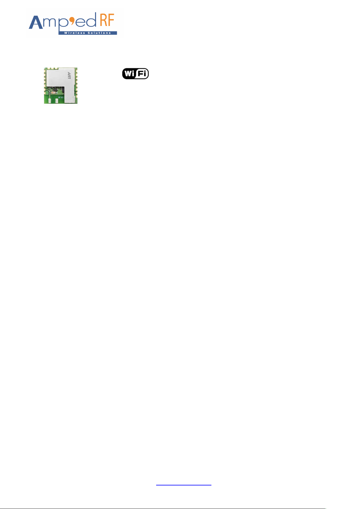
WF60 Product Specification
13.5mm x 14.6mm x 2.7 mm
Description
Amp’ed RF Tech presents the WF60 dual band
WiFi module: 802.11abgn. The WF60 is a small
footprint low cost RF module intended to help
customers shorten product development cycles
and reduce cost. It’s fully compatible with Linux &
Android systems, or our own upper layer stack,
Amp’ed UP, for a complete host & controller
solution.
Features
WLAN
802.11a: OFDM
802.11b: DSSS
802.11g/n-HT20: OFDM
Dual Band: 2.4GHz and 5GHz
Lower sub-band: U-NII-1: 5150-5250MHz
Higher sub-band: U-NII-3: 5725-5850MHz
Output Power, +22.5dBm
Power savings mode
Transmit power back-off
Wi-Fi Direct (concurrent)
Wi-Fi Display
Wi-Fi Protected Setup
Soft Access Point
Hotspot 2.0
Security: WPAI/WPA2, AES, WEP
Hardware
Interface, SDIO 2.0 or SPI
1 LPO input
Standby current, 40 μA
RoHS conformance
FCC/IC certified TBD
www.ampedrftech.com
2
Page 3

Contents
1. Hardware Specifications ................................................................................................... 4
1.1. Recommended Operating Conditions ................................................................................................................ 4
1.2. Absolute Maximum Ratings ............................................................................................................................... 4
1.3. I/O Operating Conditions ................................................................................................................................... 4
2. Hardware Block Diagram ................................................................................................... 5
3. Hardware Design ................................................................................................................ 6
4. Startup behavior ................................................................................................................ 8
4.1. RESET and PMUEN ............................................................................................................ 8
4.2. SDIO and SPI interface ...................................................................................................... 8
5. Regulatory Compliance ..................................................................................................... 8
5.1. Modular Approval, FCC and IC ........................................................................................................................ 10
5.2. FCC Label Instructions .................................................................................................................................... 10
www.ampedrftech.com
3
Page 4
1. Hardware Specifications
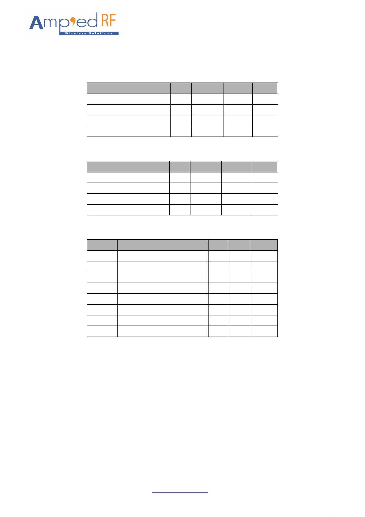
General Conditions (VIN= 3.6V and 25°C)
1.1. Recommended Operating Conditions
Rating Min Typical Max Unit
Operating Temperature Range -10 - 60 °C
Supply Voltage VIN 2.3 3.6 4.8 Volts
Signal Pin Voltage - 1.8 - Volts
RF Frequency 2400 - 2483.5 MHz
1.2. Absolute Maximum Ratings
Rating Min Typical Max Unit
Storage temperature range -55 - +150 °C
Supply voltage VIN -0.3 - +5.0 Volts
I/O pin voltage VIO -0.3 - +2.5 Volts
RF input power - - -5 dBm
1.3. I/O Operating Conditions
Symbol Parameter Min Max Unit
VIL Low-Level Input Voltage - 0.6 Volts
VIH High-Level Input Voltage 1.3 - Volts
VOL Low-Level Output Voltage - 0.2 Volts
VOH High-Level Output Voltage 1.6 - Volts
IOL Low –Level Output Current - 4.0 mA
IOH High-Level Output Current - 4.0 mA
RPU Pull-up Resistor 80 120 KΩ
RPD Pull-down Resistor 80 120 KΩ
www.ampedrftech.com
4
Page 5
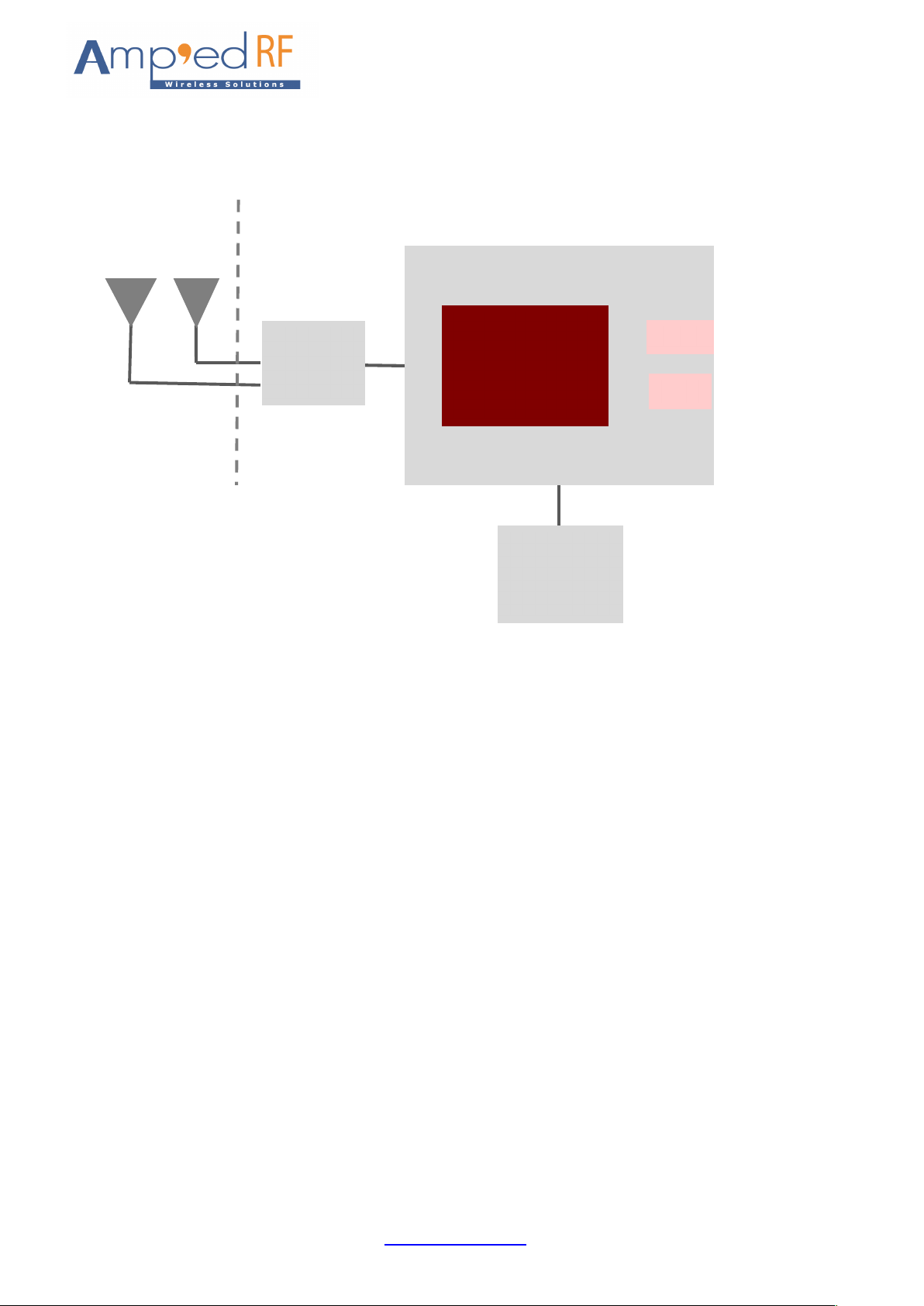
2. Hardware Block Diagram
SPI
SDIO
2.4GHz
5GHz
RF
Switch
ACC1340
WLAN
Crystal
26MHz
±20ppm
www.ampedrftech.com
5
Page 6
3. Hardware Design
All unused pins should be left floating; do not ground.
All GND pins must be well grounded.
The area around the antenna should be free of any ground planes, power planes, trace routings, or metal
for at least 6.5 mm in all directions.
Traces should not be routed underneath the module.
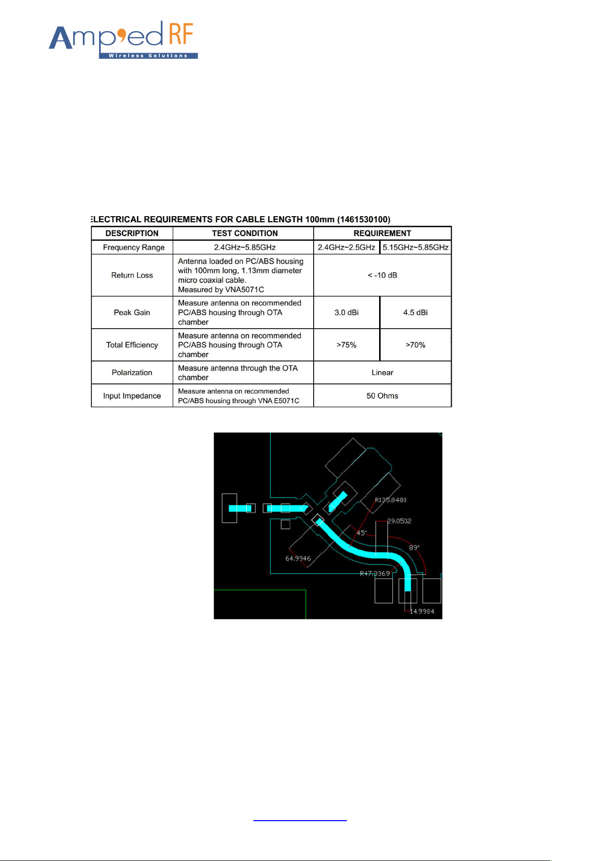
ANT 2.4G and ANT 5G:RF bi-directional antenna port matched to 50Ω, molex 1461530100.
RF traces must be as short as possible for best RF performance,like below.
RF traces must be routed on the top layer, far away from other high speed signal traces.
Digital traces should not be placed directly under RF trace layers.
All RF traces must have a solid ground plane below.
www.ampedrftech.com
6
Page 7

3.1. Module Reflow Installation
The WF60 is a surface mount Bluetooth module supplied on a 18 pin, 6-layer PCB. The final assembly
recommended reflow profiles are:
For RoHS/Pb-free applications, Sn96.5/Ag3.0/Cu0.5 solder is recommended.
Maximum peak temperature of 230° - 240°C (below 250°C).
Maximum rise and fall slope after liquidous of < 2°C/second.
Maximum rise and fall slope after liquidous of < 3°C/second.
Maximum time at liquidous of 40 – 80 seconds.
www.ampedrftech.com
7
Page 8

4. Startup behavior
4.1. RESET and PMUEN
A valid reset shall be obtained by maintaining RESET active (low) for at least two cycles of LPO after
VIN is stable within its operating range. There is no constraint on the activation of the other supplies
during this process.
4.2. SDIO and SPI interface
SDIO 5 is the selection pin; the state of this pin is monitored on the rising edge of RESET.
LOW selects SPI
HIGH selects SDIO
5. Regulatory Compliance
Federal Communications Commission statement:
This module has been tested and found to comply with the FCC Part15.
These limits are designed to provide reasonable protection against harmful interference in approved
installations. This equipment generates, uses, and can radiate radio frequency energy and, if not
installed and used in accordance the instructions, may cause harmful interference to radio
communications. However, there is no guarantee that interference will not occur in a particular
installation.
This device complies with part 15 of the FCC Rules. Operation is subject to the following two
conditions: (1) This device may not cause harmful interference, and (2) this device must accept any
interference received, including interference that may cause undesired operation.
Modifications or changes to this equipment not expressly approved by Amp’ed RF Technology may
void the user’s authority to operate this equipment.
The modular transmitter must be equipped with either a permanently affixed label or must be
capable of electronically displaying its FCC identification number
(A) Host labeling requirement: Contains FCC ID: X3ZWFMOD10
The module is a limited single module without completed shielding case, CIIPC or new filing shall
be applied for any host equipment using this module, such as provide the completed shielding case
for this module.
(B) If the modular transmitter uses an electronic display of the FCC identification number, the
information must be readily accessible and visible on the modular transmitter or on the device in
which it is installed. If the module is installed inside another device, then the outside of the device
into which the module is installed must display a label referring to the enclosed module. This exterior
label can use wording such as the following: “Contains FCC certified transmitter module(s).”
www.ampedrftech.com
8
Page 9

To satisfy FCC RF Exposure requirements for mobile and base station transmission devices, a
separation distance of 20 cm or more should be maintained between the antenna of this device and
persons during operation. To ensure compliance, operation at closer than this distance is not
recommended. The antenna(s) used for this transmitter must not be co-located or operating in
conjunction with any other antenna or transmitter.
(C) This equipment has been tested and found to comply with the limits for a Class B digital
device, pursuant to part 15 of the FCC Rules. These limits are designed to provide reasonable
protection against harmful interference in a residential installation. This equipment generates,
uses and can radiate radio frequency energy and, if not installed and used in accordance with the
instructions, may cause harmful interference to radio communications. However, there is no
guarantee that interference will not occur in a particular installation. If this equipment does cause
harmful interference to radio or television reception, which can be determined by turning the
equipment off and on, the user is encouraged to try to correct the interference by one or more of
the following measures:
—Reorient or relocate the receiving antenna.
—Increase the separation between the equipment and receiver.
—Connect the equipment into an outlet on a circuit different from that to which the receiver is
connected.
—Consult the dealer or an experienced radio/TV technician for help.
Industry Canada statement:
Label of the end product:
The final end product must be labeled in a visible area with the following "Contains transmitter
module IC:
8828A-MOD10
"
This Class B digital apparatus complies with Canadian ICES-003.
This device contains licence-exempt transmitter(s)/receiver(s) that comply with Innovation,
Science and Economic Development Canada’s licence-exempt RSS(s). Operation is subject to the
following two conditions:
(1) This device may not cause interference; and
(2) This device must accept any interference, including interference that may cause undesired
operation of the device.
L’émetteur/récepteur exempt de licence contenu dans le présent appareil est conforme aux CNR
d’Innovation, Sciences et Développement économique Canada applicables aux appareils radio
exempts de licence. L’exploitation est autorisée aux deux conditions suivantes :
(1)L’appareil ne doit pas produire de brouillage;
(2)L’appareil doit accepter tout brouillage radioélectrique subi, même si le brouillage est
www.ampedrftech.com
9
Page 10

susceptible d’en compromettre le fonctionnement.
This equipment complies with radio frequency exposure limits set forth by the Innovation, Science
and Economic Development Canada for an uncontrolled environment.
This equipment should be installed and operated with a minimum distance of 20 cm between the
device and the user or bystanders.
This device must not be co-located or operating in conjunction with any other antenna or
transmitter.
Cet équipement est conforme aux limites d'exposition aux radiofréquences définies par la
Innovation, Sciences et Développement économique Canada pour un environnement non contrôlé.
Cet équipement doit être installé et utilisé avec un minimum de 20 cm de distance entre le
dispositif et l'utilisateur ou des tiers.
Ce dispositif ne doit pas être utilisé à proximité d’une autre antenne ou d’un autre émetteur.
5.1. Modular Approval, FCC and IC
FCC ID: X3ZWFMOD10
IC: 8828A-MOD10
In accordance with FCC Part 15, the WF60 is listed above as a Limited Modular Transmitter
device.
5.2. FCC Label Instructions
The outside of final products that contain a WF60 device must display a label referring to the enclosed
module. This exterior label can use wording such as the following:
Contains Transmitter Module
FCC ID: X3ZWFMOD10
Any similar wording that expresses the same meaning may be used.
www.ampedrftech.com
10
 Loading...