

Page 1
For Technical Support, Contact AMP
at (775) 345-9933 (9 am - 5 pm PST)
Advanced Microwave Products
PO Box 1437
2465 Old Highway 40 West, Suite 200
Verdi, NV 89439
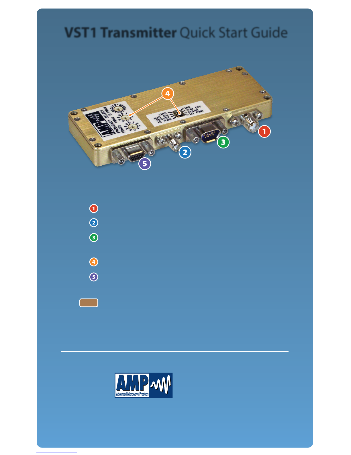
Connect Antenna to SMA Connector
Connect camera/video input source to SSMA connector
Connect audio/data inputs to MDM-9S connector
(if applicable) *see reverse side
Set conguration *see reverse side
STEP
STEP
STEP
STEP
STEP
Connect power/communications inputs to the
MDM-9P connector *see reverse side
Note
When setting up your system, the transmit and receive
antennas should be greater than 25 feet apart to
prevent serious damage to or destruction of the
receiver’s front end
VST1 Transmitter Quick Start Guide
Page 2
AQS-VST1-D
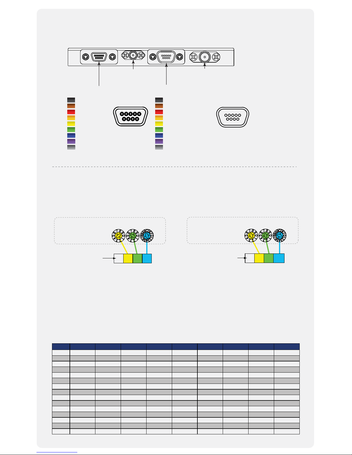
How to Set Your Transmitter Conguration
Frequency Band
“Cong Select” Preset
Preset U1 L1 L2 S1 S2 S3 C1 C2 C3
1 340 MHz 1435 MHz 1700 MHz 2200 MHz 2400 MHz 2200 MHz 4400 MHz 4900 MHz 4400 MHz
2 344 MHz 1442 MHz 1711 MHz 2214 MHz 2407 MHz 2221 MHz 4436 MHz 4907 MHz 4443 MHz
3 349 MHz 1449 MHz 1721 MHz 2228 MHz 2414 MHz 2243 MHz 4471 MHz 4914 MHz 4486 MHz
4 353 MHz 1456 MHz 1732 MHz 2243 MHz 2421 MHz 2264 MHz 4507 MHz 4921 MHz 4528 MHz
5 357 MHz 1464 MHz 1743 MHz 2257 MHz 2428 MHz 2285 MHz 4543 MHz 4928 MHz 4571 MHz
6 361 MHz 1471 MHz 1754 MHz 2271 MHz 2435 MHz 2307 MHz 4579 MHz 4935 MHz 4614 MHz
7 366 MHz 1478 MHz 1764 MHz 2285 MHz 2442 MHz 2328 MHz 4614 MHz 4942 MHz 4657 MHz
8 370 MHz 1485 MHz 1775 MHz 2300 MHz 2450 MHz 2350 MHz 4650 MHz 4950 MHz 4700 MHz
9 374 MHz 1492 MHz 1786 MHz 2314 MHz 2457 MHz 2371 MHz 4686 MHz 4957 MHz 4742 MHz
A 379 MHz 1499 MHz 1796 MHz 2328 MHz 2464 MHz 2392 MHz 4721 MHz 4964 MHz 4785 MHz
B 383 MHz 1506 MHz 1807 MHz 2342 MHz 2471 MHz 2414 MHz 4757 MHz 4971 MHz 4828 MHz
C 387 MHz 1514 MHz 1818 MHz 2356 MHz 2478 MHz 2435 MHz 4793 MHz 4978 MHz 4871 MHz
D 391 MHz 1521 MHz 1829 MHz 2371 MHz 2485 MHz 2456 MHz 4829 MHz 4985 MHz 4913 MHz
E 396 MHz 1528 MHz 1839 MHz 2385 MHz 2492 MHz 2478 MHz 4864 MHz 4992 MH
z 4956 MHz
F 399.9 MHz 1535 MHz 1850 MHz 2399 MHz 2499 MHz 2499 MHz 4900 MHz 4999 MHz 4999 MHz
FREQUENCY MULTIPLIER
100MHz
10MHz 1MHz
Your Frequency
44 1 3
This digit is always
constant for a given band
and is not adjustable
Transmitter/Receiver
rotary switches
for frequency selection
MHz
Diagram A - For 1 MHz Step - L-Band, S-Band, and C-Band
FREQUENCY MULTIPLIER
10MHz
1MHz 0.1MHz
Your Frequency
73 2 .1
This digit is always
constant for a given band
and is not adjustable
Transmitter/Receiver
rotary switches
for frequency selection
MHz
Diagram B - For 100 KHz Step - UHF
The VST1 Transmitter has three modes for conguring the unit: Local Mode, Preset Mode, and
Remote Mode (see manual for details). Local Mode utilizes DIP switches for conguring equipped
options and rotary switches for frequency selection as shown below:
Pre-set Mode, selected when the two 10-position (BCD, 0-9) switches are set to zero and the 16-position
(binary, 0-F) is set to any position 1-F, allows local selection among 15 pre-set congurations. The VST1
transmitter ships from the factory with the 15 pre-sets congured with all options “ON” and set to their
max settings with the frequencies set per the table below. Pre-sets may be changed as outlined in the
ICD (Interface Control Document) via the communications port. Pre-sets are reprogrammable using
Remote Mode, selected when all three rotary switches are set to zero. “Remote Only” VST1 transmitters
have no rotary switches installed. See the product manual for more details.
SSMA Female
Video Input
(Connect to Camera)
SMA Female
RF Output
(Connect to Antenna)
MDM-9P
Power & Programming
1:
2:
3:
4:
5:
6:
7:
8:
9:
+11 to 16 VDC Input
Ground
Ground
Ground
12 VDC Out
NC/TX CommTX Comm+
RX Comm+
NC/RX Comm-
MDM-9S
Audio/Data Input
1:
2:
3:
4:
5:
6:
7:
8:
9:
Sub1 Mic/TTL
Sub1 Line/RS232
Ground
Sub2 Mic/TTL
Sub2 Line/RS232
Ground
NC
NC
Ground
Wiring Your VST1 Transmitter
(Audio/Data Connections are Dependent on Conguration )
1 5
6 9
15
69
NC = No Connection
 Loading...