

Page 1
Page 2

AMN-VHT1-B
TABLE OF CONTENTS
1.! INTRODUCTION 1!
1.1.! Purpose and Function 1!
1.2.! Capabilities 1!
1.3.! Environmental Requirements 1!
2.! VHT1 TRANSMITTER 2!
2.1.! VHT1 Specifications 2!
2.2.! VHT1 Mechanical Drawing and Connector Pin-Outs 3!
2.3.! List of Items Furnished 3!
2.4.! List of Items Required 3!
3.! SAFETY PRECAUTIONS 4!
4.! PREPARATION FOR USE 5!
4.1.! Unpacking 5!
4.2.! Transmitter Pre-Test 5!
5.! INSTALLATION AND OPERATING INSTRUCTIONS 5!
5.1.! Local Programming 5!
5.1.1.!“F” – Frequency Mode: 6!
5.1.2.!“d” – Data Type Mode: 6!
5.1.3.!“A” – Audio Type Mode: 7!
5.1.4.!“S” – Subcarrier Mode: 7!
5.1.5.!“I” – Video Inversion Mode: 7!
5.1.6.!“P” – Output Power Mode: 8!
5.1.7.!“r” – RF Output Mode: 8!
5.1.8.!“C” – Preset Mode: 8!
5.2.! Use of Heat Sink 9!
5.3.! Connectors 9!
5.4.! REMOTE COMMANDS 10!
5.5.! Initial Adjustments and Settings 10!
5.6.! Shut Down 10!
6.! MAINTENANCE INSTRUCTIONS 10!
6.1.! Cleaning 10!
6.2.! Troubleshooting 10!
6.3.! Preparation for Reshipment 11!
6.4.! Returning an Item 11!
7.! WARRANTY STATEMENT 12!
Page 3

AMN-VHT1-B 1
1. INTRODUCTION
Thank you for choosing this AMP Wireless Video Product. Every effort has been made to design and
manufacture a quality product that will meet your surveillance needs for many years. Please visit our
website (www.advmw.com) for information on other products and for datasheets, quick start guides,
model number builders, operation manuals, and other related materials.
If you have any questions regarding this product or if you require technical assistance, please feel free to
contact us at (775) 345-9933.
1.1. Purpose and Function
VHT1 series Video/Audio/Data Transmitters are developed and manufactured by Advanced Microwave
Products (AMP), and are designed for color or monochrome video, audio, and/or data transmission.
VHT1 series transmitters are best operated with AMP’s V or P series receivers but are compatible with
most other analog FM video receivers on the market.
1.2. Capabilities
AMP Transmitters are designed for harsh environments and feature robust packaging and connectors.
Compact package sizes provide versatility in unit placement and system applications.
AMP Transmitters require no tuning or adjustments. All units operate directly with any standard video
camera or display. Power can be derived from batteries, simple power supplies, or vehicle power.
Whip or “rubber duck” antennas are adequate for most applications.
1.3. Environmental Requirements
AMP Transmitters are designed for indoor or outdoor use. Precautions should be taken when exposing
the products to the elements. Do not expose to 100% humidity.
Transmitters should be located in areas where the ambient temperature does not exceed the maximum
operating temperature indicated in the specifications. Placement in confined locations with minimal
airflow, in direct sunlight in areas of temperature extremes, or in proximity to other devices that generate
heat, such as power supplies, heating systems, etc., should be avoided. Temperatures exceeding +75°C
may cause permanent damage to the equipment.
When not used for extended periods of time, external connections, including power cable, video cable,
and antenna, should be removed and the units covered, boxed, or crated and stored in a clean, dry place.
Page 4
AMN-VHT1-B 2
2. VHT1 TRANSMITTER
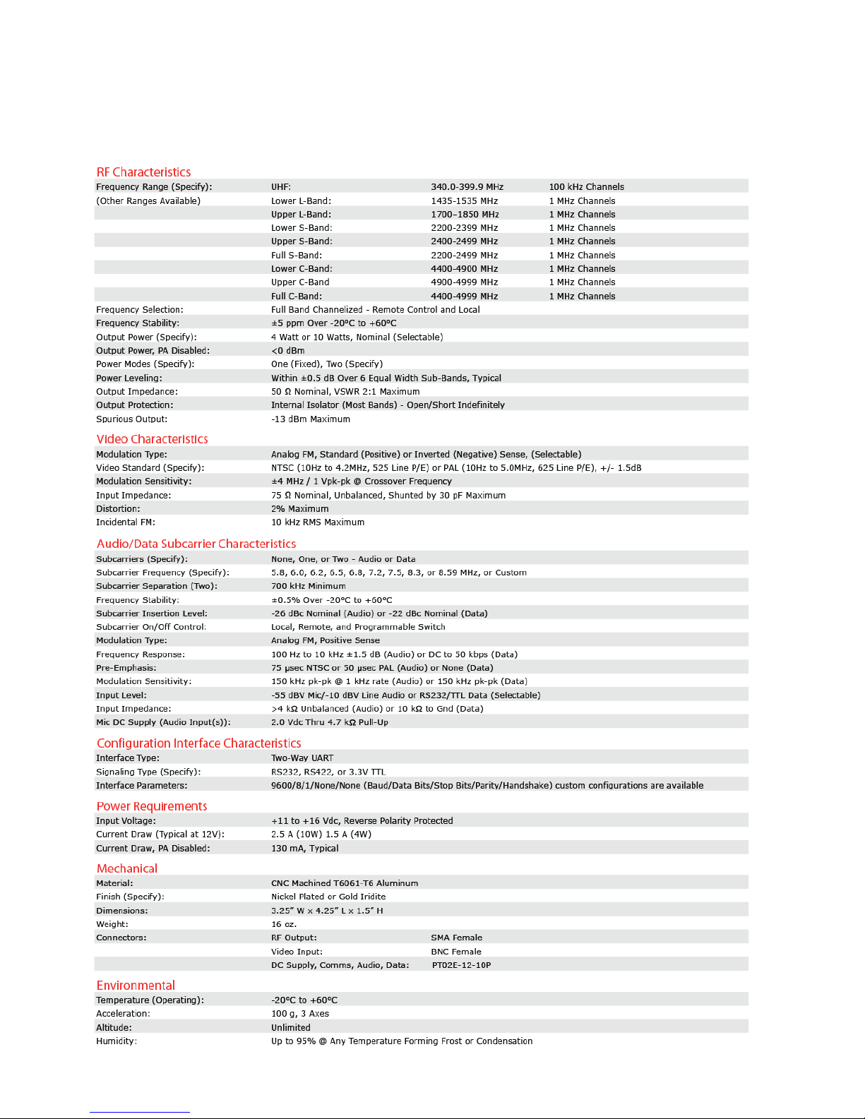
2.1. VHT1 Specifications
Page 5
AMN-VHT1-B 3
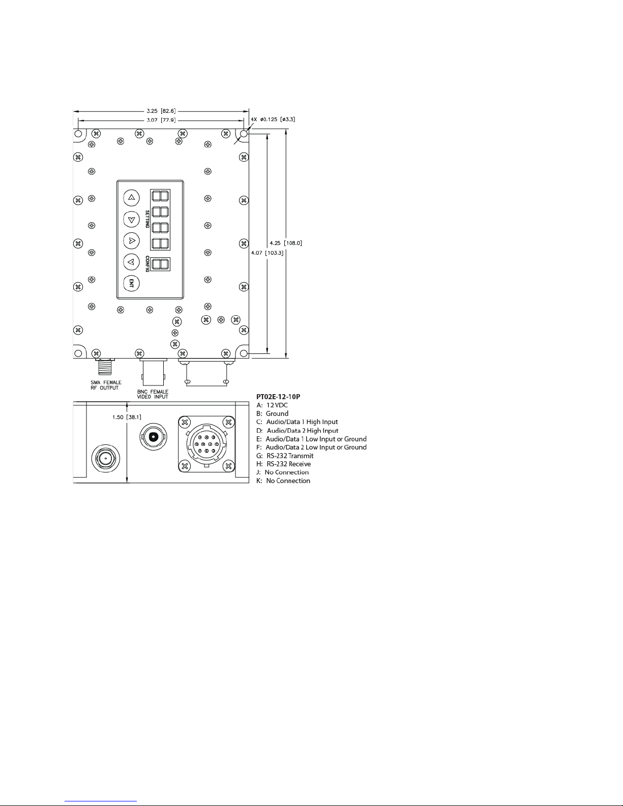
2.2. VHT1 Mechanical Drawing and Connector Pin-Outs
2.3. List of Items Furnished
• (1) VST1 Transmitter (configured as ordered)
2.4. List of Items Required
• Antenna, Type SMA Plug (Male) Connector
• Video Source, Type BNC Jack (Female) Connector
• Power/Audio/Comms Mating Connector (Mates with PT02E-12-10P)
• Heatsink
Page 6
AMN-VHT1-B 4
3. SAFETY PRECAUTIONS
Transmitters should be handled with caution like any electrical or electronic device. Do not handle the
units or associated cabling with wet hands or materials.
Connections should be made only to previously-tested, active power sources (outlets or batteries) of the
correct voltage, and each connector should be inserted only into its designated port. All connections
should be checked to ensure they are firmly in place.
WARNING! RF RADIATION HAZARD
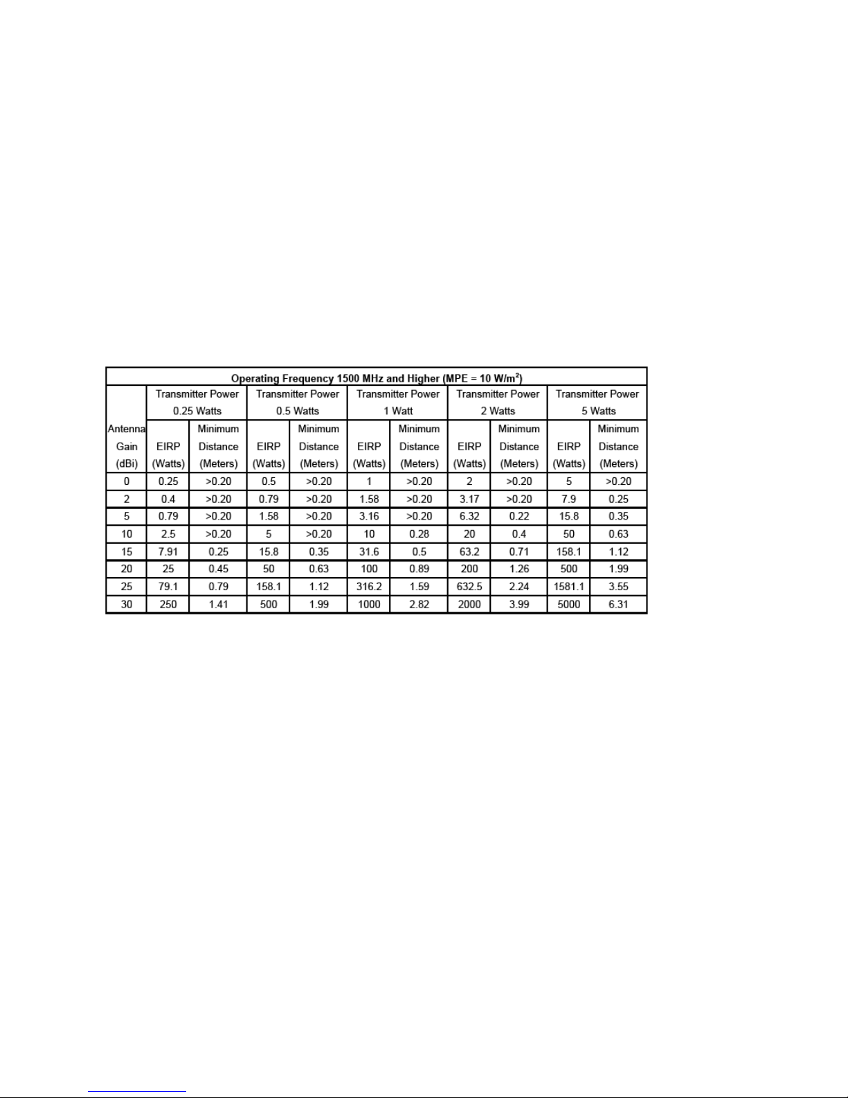
In order to keep the RF Exposure within the FCC 1.1310 limit, a safe personal distance from the antenna
must be maintained according to the below tables. The first table is for transmitters operating 1500 MHz
or higher where the Maximum Permissible Exposure (MPE) is 10 Watts/meter2. See following for details
on calculation of safe personal distances.
MAINTAIN A SAFE PERSONAL DISTANCE FROM THE ANTENNA WHILE TRANSMITTER IS
OPERATIONAL.
FAILURE TO MAINTAIN A SAFE PERSONAL DISTANCE FROM THE ANTENNA MAY RESULT IN
PERSONAL INJURY.
Page 7

AMN-VHT1-B 5
4. PREPARATION FOR USE
4.1. Unpacking
Carefully remove the product from the shipping container and make sure all listed furnished items are
included as noted in the respective section. Inspect all items for damage. If any item is omitted from the
shipment or appears damaged, contact AMP with detailed description of problem.
4.2. Transmitter Pre-Test
Although each unit is thoroughly tested at the factory for both functional and environmental performance,
a minimal amount of pre-testing should be done by the operator before placing the transmitter into
service. The transmitter, an appropriate receiver, transmit and receive antennas, a video camera, a video
monitor, proper cabling, and DC power supplies are the only components required to perform a functional
test of the transmitter. If testing audio or data, an audio source (microphone or line level) or data source
and a speaker or headphones (audio) or data monitor will also be required.
Verify DC power supplies are between +11 and +16 Vdc. With the DC Power Cable (PT02E-12-10P
connector) DISCONNECTED from the transmitter, connect DC power supply to DC Power Cable (Pin A =
positive DC input, Pin B = negative DC input (ground)). Do not connect DC Power Cable to transmitter
until all other connections are complete.
Connect the transmit antenna to transmitter RF output connector (SMA). Connect the Video to the
transmitter video input connector (BNC). Connect the Video Cable between the Video Adapter Cable and
video camera. If testing audio or data, connect the audio or data source to the Power/Audio/Data/Comms
Cable (PT02E-12-10P connector) and cable to the transmitter. Refer to Section 2.2 for a complete
transmitter wiring diagram.
Configure transmitter as instructed in Section 5. Connect DC Power Cable to transmitter (mates to
PT02E-12-10P connector on transmitter). Video should be observed on the monitor and audio heard
through the speaker / headphones (or data present) once the transmitter locks on frequency (requires
several seconds). If no video, data, or audio is present, refer to Section 6.2 for troubleshooting
instructions.
5. INSTALLATION AND OPERATING INSTRUCTIONS
Transmitter configuration is available via “Local”, “Preset”, or “Remote” modes. See the V Series ICD for
details on controlling your transmitter remotely or reprogramming its presets. Local configuration and
Presets can be set on the display on the transmitter.
5.1. Local Programming
The transmitter display is always active regardless of whether the unit is in “Local”, “Preset”, or “Remote”
mode. The unit responds to local button presses and remote commands in the same manor and updates
whatever parameter is being changed accordingly. When a transmitter is turned on, it will be in the last
mode it was on when it was last turned off.
To activate or change modes, press the button on the display and the CONFIG character will be
flashing. Use the buttons to scroll through the available modes. When the CONFIG character
displays the mode you want to configure, press the button to select it.
Page 8
AMN-VHT1-B 6
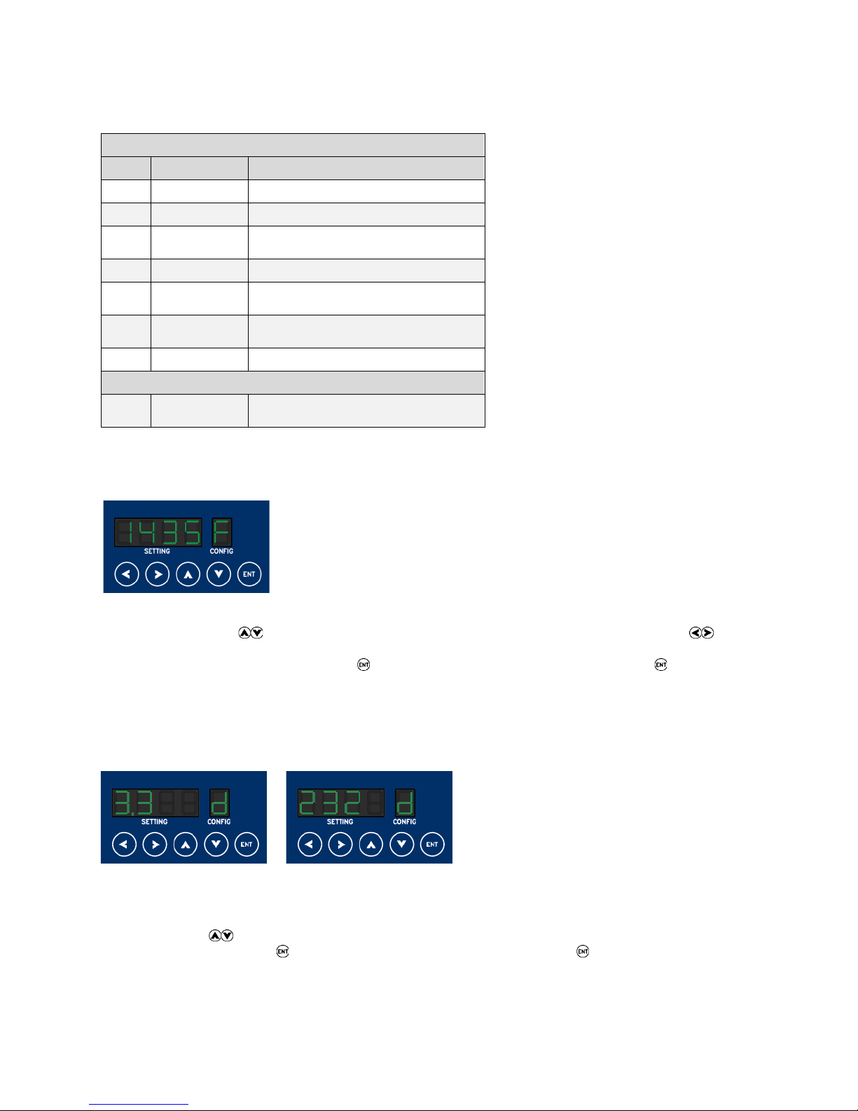
The display has 1 “Preset” mode (C) and up to 7 “Local” configuration modes:
Local Configuration Modes
Mode
Description
Selectable Options
F
Frequency
Frequency in 1 MHz Steps
d
Data Type
3.3V TTL (3.3) or RS232 (232)
A
Audio Type
Mic -55 dBV (-55) or Line -10 dBV
(-10)
S
Subcarrier
On or OFF
I
Video
Inversion
On or OFF
P
Output
Power
HI (10W) or Lo (4W)
r
RF Enable
On or OFF
Preset Mode
C
Presets
1, 2, 3, 4, 5, 6, 7, 8, 9, A, B, C, D,
E, F
5.1.1. “F” – Frequency Mode:
When you select Frequency Mode or “F” you will notice that the last digit of the displayed frequency is
now flashing. Use the buttons to move through the available frequencies. You can use the
buttons to move through the digits (ones, tens, and hundreds). The active digit will be flashing. Once you
have the frequency you desire, press the button and the “F” will be flashing. Press the button a
second time to confirm your frequency selection, at which time the “F” will no longer be flashing.
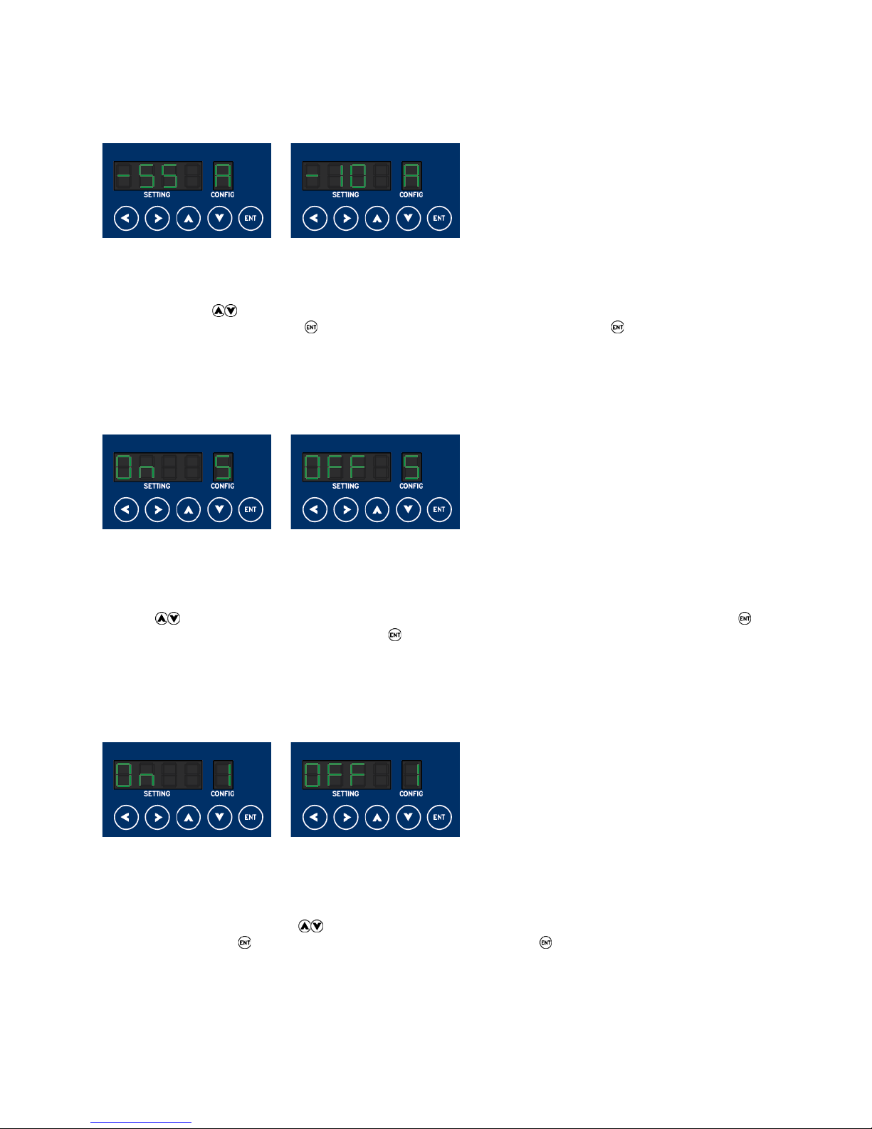
5.1.2. “d” – Data Type Mode:
The Data Type mode or “d” will only be available on transmitters equipped with a data subcarrier.
When you select Data Type mode or “d” you will notice that the currently selected Data Type is now
flashing. Use the buttons to select between 3.3V TTL (3.3) or RS232 (232). Once you have the
option you desire, press the button and the “d” will be flashing. Press the button a second time to
confirm your selection, at which time the “d” will no longer be flashing.
Page 9
AMN-VHT1-B 7
5.1.3. “A” – Audio Type Mode:
The Audio Type mode or “A” will only be available on transmitters equipped with an audio subcarrier.
When you select Audio Type mode or “A” you will notice that the currently selected Audio Type is now
flashing. Use the buttons to select between Mic -55 dBV (-55) or Line -10 dBV (-10). Once you have
the option you desire, press the button and the “A” will be flashing. Press the button a second time
to confirm your selection, at which time the “A” will no longer be flashing.
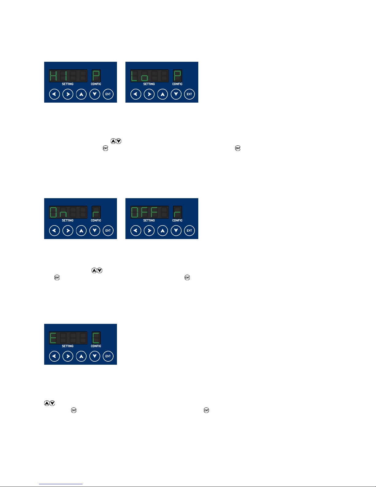
5.1.4. “S” – Subcarrier Mode:
The Subcarrier mode or “S” will only be available on transmitters equipped with one or two subcarriers
(audio or data). If your transmitter is equipped with two subcarriers, the selection will apply to both.
When you select Subcarrier mode or “S” you will notice that the current subcarrier status is now flashing.
Use the buttons to select between On and OFF. Once you have the option you desire, press the
button and the “S” will be flashing. Press the button a second time to confirm your selection, at which
time the “S” will no longer be flashing.
5.1.5. “I” – Video Inversion Mode:
The Video Inversion mode or “I” will apply to all VHT1 transmitters as it is included as standard on all
units.
When you select Video Inversion mode or “I” you will notice that the currently selected Video Inversion
status is now flashing. Use the buttons to select between On and OFF. Once you have the option
you desire, press the button and the “I” will be flashing. Press the button a second time to confirm
your selection, at which time the “I” will no longer be flashing.
Page 10
AMN-VHT1-B 8
5.1.6. “P” – Output Power Mode:
The Output Power mode or “P” will only be available on transmitters equipped with both 4 watt and 10
watt outputs.
When you select Output Power mode or “P” you will notice that the currently selected Output Power level
is now flashing. Use the buttons to select between HI (10W) and Lo (4W). Once you have the option
you desire, press the button and the “P” will be flashing. Press the button a second time to confirm
your selection, at which time the “P” will no longer be flashing.
5.1.7. “r” – RF Output Mode:
The RF Output mode or “r” will apply to all VHT1 transmitters.
When you select RF Output mode or “r” you will notice that the currently selected RF Output status is now
flashing. Use the buttons to select between On and OFF. Once you have the option you desire, press
the button and the “r” will be flashing. Press the button a second time to confirm your selection, at
which time the “r” will no longer be flashing.
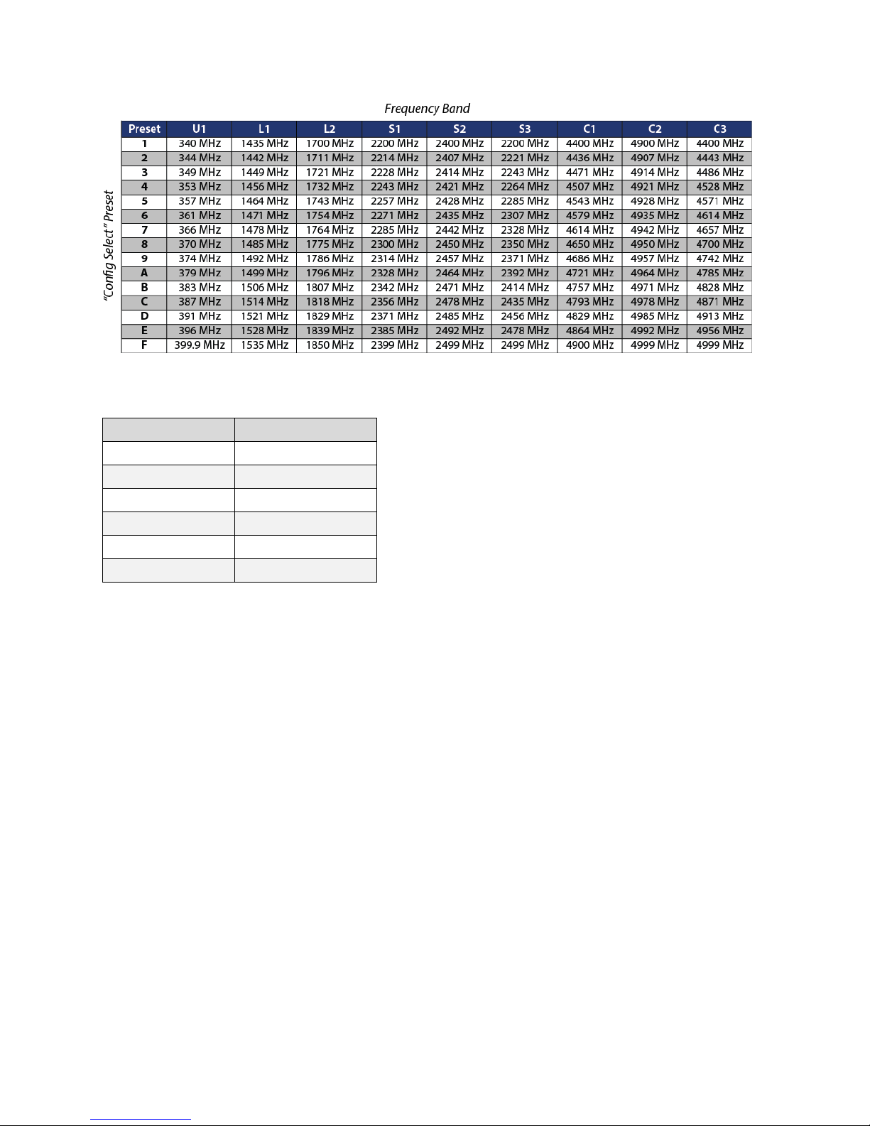
5.1.8. “C” – Preset Mode:
The Preset mode or “C” will apply to all VHT1 transmitters. Preset mode is independent of all the other
modes. When you are in Preset mode your transmitter will be set to the last known preset configuration.
When you select Preset mode or “C” you will notice that the current active preset is now flashing. Use the
buttons to select a preset from 1 to F (15 total). Once the preset you want to select is displayed,
press the button and the “C” will be flashing. Press the button a second time to confirm your
selection, at which time the “C” will no longer be flashing.
A set of Presets come preconfigured on your transmitter based on frequency band (see the chart below):
Page 11
AMN-VHT1-B 9
In addition to the frequency, the default presets include the following settings, when applicable:
Setting
Preset Default
Data Type
RS232
Audio Type
-10 dBV
Subcarrier
On
Video Inversion
OFF
Output Power
HI
RF Output
On
You can reprogram your presets using HyperTerminal and the serial comm programming interface. See
the V Series ICD for programming details.
5.2. Use of Heat Sink
VHT1 Transmitters require the use of a heat sink or must be securely fastened to an adequate heat
sinking object or surface. Use of thermal grease, such as Wakefield Engineering 120 Series Thermal
Compound, to improve thermal conduction between transmitter base plate and heat sinking surface will
reduce unit temperature and increase product reliability.
5.3. Connectors
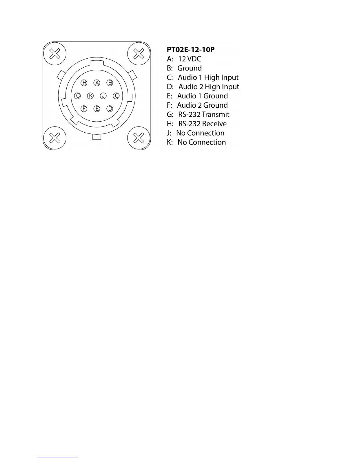
The VHT1 transmitters use a circular 10 pin MIL Spec connector for DC power, audio or data subcarrier
inputs, and RS232 communications. The pin configuration is shown in the diagram below.
The RF output is an industry standard SMA connector. The video input is an industry standard BNC
connector.
Page 12
AMN-VHT1-B 10
5.4. REMOTE COMMANDS
The VHT1 transmitter accepts commands from serial controllers. Setup and commands are detailed in
the V Series ICD.
5.5. Initial Adjustments and Settings
There are no initial adjustments or settings necessary to use AMP products other than proper
configuration of the switches as outlined above in Section 5.3. To assure optimum performance, the user
should be familiar with the camera, monitor, microphone, speaker/headphones used with this video
system.
5.6. Shut Down
If the transmitter or receiver is to be shut down only briefly, simply remove DC voltage from the DC Power
Cable or disconnect DC Power Cable from transmitter. If the unit is to be shut down for an extended
period, all external cabling including the antenna should be removed and the unit should be stored in a
container and placed in a clean, dry environment.
6. MAINTENANCE INSTRUCTIONS
6.1. Cleaning
AMP Transmitters should be periodically wiped off with a clean, damp cloth. For more thorough cleaning,
dampen a clean cloth with glass cleaner and wipe off unit. Ensure units are completely disconnected
from their power sources before cleaning.
6.2. Troubleshooting
To avoid poor performance, ensure all mating connectors are tightly fastened, clean, and have no pins
bent or damaged.
Verify the connections and setup in section 5. If poor or no operation is observed, ensure the external DC
voltage supply is between +11 and +16 Vdc with correct polarity. All AMP Transmitters have over-voltage
Page 13

AMN-VHT1-B 11
and reverse polarity protection circuits. If the input voltage is over +16 Vdc, remove the DC Power Cable
from the unit, reduce the DC voltage to between +11 and +16 Vdc, and reconnect the DC Power Cable.
If the input voltage is negative polarity, remove the DC Power Cable from the unit, reverse the
connections between the DC voltage supply and DC Power Cable, and reconnect the DC Power Cable.
If all connections are adequate, switches are correctly configured, and DC voltage is correctly applied,
check the video camera, video cable, and antenna for damage. A monitor may be connected directly to
the camera to verify proper camera operation.
If these efforts fail, do not attempt to repair the unit. Please contact AMP with a detailed description of the
problem. Depending on the nature of the problem, AMP may provide further troubleshooting assistance
or advise the entire system be returned for repair and retest.
Caution: Removal of the cover constitutes breaking the seal and VOIDS PRODUCT WARRANTY.
6.3. Preparation for Reshipment
If the transmitter, receiver, and/or any other purchased item(s) are to be shipped to another location or
returned for repair or realignment, use the original packaging or a sturdy box with sufficient protective
material to avoid damage from movement or exposure during transit. Remove all external connections
(cables, antenna, etc.) prior to shipping.
6.4. Returning an Item
Please contact AMP customer service at (775) 345-9933 for a Return Authorization Number before
returning an item. The AMP ship-to address is listed below. When returning an item, always include a
contact name and phone number and a detailed description of the problem with your shipment.
Advanced Microwave Products
Advanced Microwave Products
PO Box 1437
2465 Old Highway 40 West, Suite 200
Verdi, NV 89439
Page 14

AMN-VHT1-B 12
7. WARRANTY STATEMENT
Advanced Microwave Products (AMP) warrants these products to be free from defects in material and workmanship
for a period of one year from date of original shipment. AMP shall, at its option, either repair or replace products
which prove to be defective.
No products may be returned to AMP without the permission of AMP. BUYER, after obtaining a return authorization
from AMP, shall return the equipment to AMP accompanied by a report stating as completely as possible the reason
for return, the defects, and the conditions under which they occurred. BUYER shall pay all shipping charges, duties,
and fees for the return of products to AMP. All warranty services will be carried out at AMP’s facility. AMP will pay
for the return of products to the BUYER.
All articles are to be properly and carefully inspected by BUYER upon receipt. Shipping container damage may
indicate equipment damage. All shipping damage must be promptly reported to the carrier. AMP is not liable for
shipping damage.
Limitation of Warranty: The above warranty does not apply to defects of, or resulting from the following:
1) End items included as part of a system, but not designed by, AMP are subject only to warranty as may be
obtained from the original manufacturers. Such items include, but are not limited to, batteries, cameras,
monitors, cabling, etc.,
2) Operation outside of the environmental specifications of the product,
3) Unauthorized modifications, misuse, or mishandling,
4) Improper or inadequate maintenance by BUYER,
5) Improper or inadequate heat sinking by BUYER,
6) Improper installation or improper testing,
7) Malfunction of connected hardware.
THIS WARRANTY IS EXCLUSIVE AND NO OTHER WARRANTY, WHETHER WRITTEN OR ORAL, IS
EXPRESSED OR IMPLIED. AMP SPECIFICALLY DISCLAIMS THE IMPLIED WARRANTIES OR
MERCHANTABILITY AND FITNESS FOR A PARTICULAR PURPOSE.
The remedies set forth above are the purchaser’s sole and exclusive remedies. In no circumstances shall AMP
assume liability for loss, damage, or consequential expense (including loss of profits) whether based on contract, tort,
or any other legal theory, arising directly or indirectly from the use of its equipment separately or in combination with
other equipment.
 Loading...