

Page 1

MPX-Series Diesel Engine
Shut Down Valves
(Manual Reset / Air Pressure and Manual
Closure Options)
Selection, Application and Maintenance
Valve Numbers
MPX-300 MPX-301 MPX-302 MPX-303 MPX-310
MPX-500 MPX-501 MPX-502 MPX-503 MPX-510
MPX-800 MPX-801 MPX-802 MPX-803
CE236 (9) 1110 MPX
Page 2
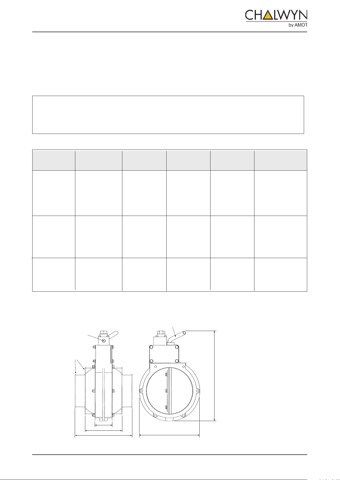
DESCRIPTION
1/8" NPT for
connecting air
pressure supply
Optional Hose
Adaptors
C1
C2 (min)
C2 (max)
Reset Lever
B
A
A range of 3”, 5” and 8” bore slim butterfly air intake shut down valves with air pressure actuated shut down
combined with manual reset and the optional addition of manual shut down. Suitable for both hazardous
and non-hazardous area applications. MPX valves are available in basic flange mounted form or fitted with
hose adaptors. Valve body and disc are manufactured in corrosion resistant hard anodised aluminium with
PTFE coating. The valve spindle and mechanism is made from stainless steel.
Notes:
Maximum temperature of the engine intake air at the MPX valve not to exceed 150°C. (See also
‘Installation” - page 5).
For alternative types of air pressure actuated Chalwyn valves see brochure CE218.
Main Dimensions (mm)
Valve Type
MPX-300
MPX-301
MPX-302
MPX-303
Nominal Bore
Diameter
76 (3”)
A
190.0
207.0
190.0
223.0
111.5
MPX-310
MPX-500
MPX-501
MPX-502
MPX-503
127 (5”)
246.0
263.0
246.0
279.0
167.0
MPX-510
346.5
MPX-800
MPX-801
MPX-802
203 (8”)
362.0
346.5
377.5
257.0
MPX-803
Valve Types MPX-300, MPX-500 and MPX-800
(Air Pressure Shut Down, Manual Reset)
B
C1
37.5
45.5
56.0
C2
minimum & maximum
82.5 to 112.5
102.0 to 157.5
136.5 to 185.5
2
MPX DIESEL ENGINE SHUTDOWN VALVES
CE236 (9)
Valve models MPX-310 and MPX-510 have a
built-in microswitch. This enables an indica-
tion of the valve open/close status. The micro-
switch connections are made as follows:
Brown = supply - common
Blue = makes circuit when valve is closed
Black = make circuit when valve is open
Maximum rating of microswitch at 12 or
24 V = 2 amp
T: +44 (0)1284 715739
Page 3
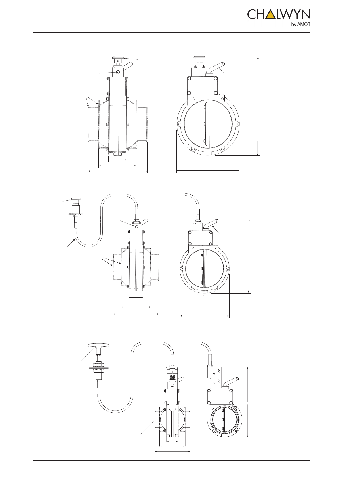
Reset Lever
B
A
1/8" NPT for
connecting air
pressure supply
Optional Hose
A
daptors
Reset Lever
Stop Button
C1
C2 (min)
C2 (max)
B
A
Reset Lever
B
A
Valve Types MPX-301, MPX-501 and MPX-801
A
C1
C2 (min)
C2 (max)
B
Optional Hose Adaptor
(One each side)
Cable Length Options
- see under “Selection”
“PULL” Type
Manual Stop
Reset Lever
(Air Pressure and Integral Stop Button Shut Down, Manual Reset)
Valve types MPX-302, MPX-502 and MPX-802
(Air Pressure and Remote “Push” Stop Button Shut down, Manual Reset
“Push” Type
Stop Button
Ass’y RBP-100
1/8" NPT for
connecting air
pressure supply
Reset Lever
Cable Length Options
- see under “Selection”
Optional Hose
Adaptors
C1
C2 (min)
C2 (max)
A
B
Valve Types MPX-303, MPX-503 and MPX-803
(Air Pressure and Remote “Pull” Shut Down, Manual Reset)
3
MPX DIESEL ENGINE SHUTDOWN VALVES
CE236 (9)
T: +44 (0)1284 715739
Page 4
SELECTION
Determine the size and position of the MPX valve to be installed. Within the various constraints imposed in
the application, the valve should be as generously sized as possible. Check that the valve can be positioned
such that the reset lever and, where applicable, the stop button will be easily and safely accessible. For types
with a remote manual stop, position the valve and select the cable length to give a reasonably straight cable
run between the MPX valve and the proposed stop button position.
Air Pressure
A clean, dry air supply is required. An air pressure of approximately 2 bar is required to close the valve.
Maximum air pressure must not exceed 10 bar.
Cable options for use with “PUSH” button RBP-100
To suit valves MPX-302, MPX-502, or MPX-802
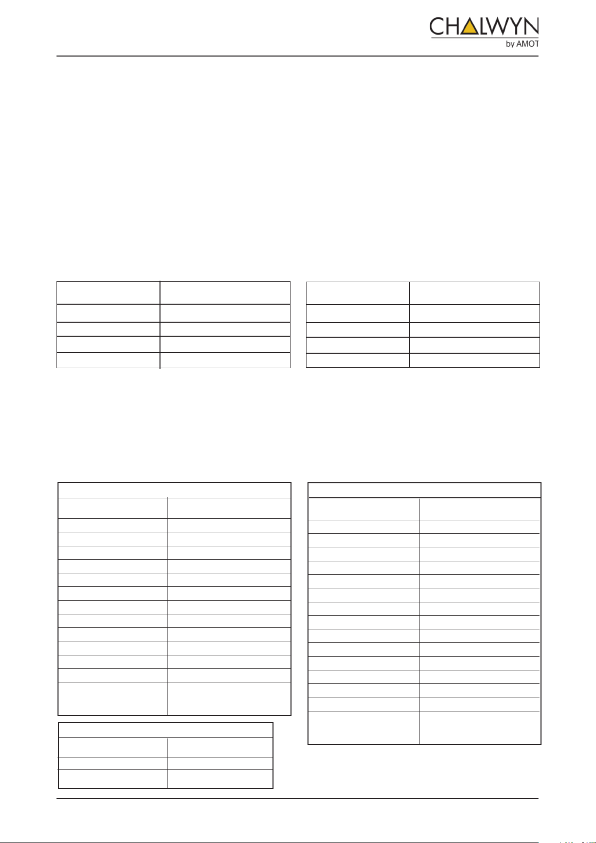
Cable part No. Length (meters)
CLP-100 1.0
CLP-150 1.5
CLP-200 2.0
CLP-300 3.0
Select the required length of the manual shut down cable
from the table . Alternative lengths may be available on
request. Also order push button assembly RBP-100.
If the valve is to be fitted into a hose as opposed to flange mounted, suitable hose adaptors may be selected from the table
below for ordering with the valve.
Cable options for use with “PULL” handle RTD-100
To suit valves MPX-303, MPX-503, or MPX-803
Cable part No. Length (meters)
CLD-100 1.0
CLD-150 1.5
CLD-200 2.0
CLD-300 3.0
Select the required length of the manual shut down cable
from the table . Alternative lengths may e available on
request. Also order handle RTD-100.
Hose Adaptor Options
76mm (3”) Bore Valves
Adaptor To Suit Hose Bore
Part Number mm (inches)
HAX-320 38 ( 11/2)
HAX-322 44.5 (13/4)
HAX-301 51 (2)
HAX-302 54 (2 1/8)
HAX-303 57 (2 1/4)
HAX-304 60 (2 3/8)
HAX-305 63.5 (2
HAX-306 67 (2 5/8)
HAX-307 70 (2 3/4)
HAX-308 73 (2 7/8)
HAX-309 76 (3)
HAX-314 89 (3 1/2)
HAX-319 102 (4)
203mm (8”) Bore Valves
Adaptor To Suit Hose Bore
Part Number mm (inches)
HAX-807 178 (7)
HAX-808 203 (8)
1
/2)
127mm (5”) Bore Valves
Adaptor To Suit Hose Bore
Part Number mm (inches)
HAX-501 89 (3 1/2)
HAX-502 92 (3 5/8)
HAX-503 95 (3 3/4)
HAX-504 98 (3 7/8)
HAX-505 102 (4)
HAX-506 105 (4 1/8)
HAX-507 108 (4 1/4)
HAX-508 111 (4 3/8)
HAX-509 114 (4 1/2)
HAX-510 117.5 (4 5/8)
HAX-511 121 (4 3/4)
HAX-512 124 (4 7/8)
HAX-513 127 (5)
HAX-518 140 (5 1/2)
HAX-523 152 (6)
4
MPX DIESEL ENGINE SHUTDOWN VALVES
CE236 (9)
T: +44 (0)1284 715739
Page 5
INSTALLATION
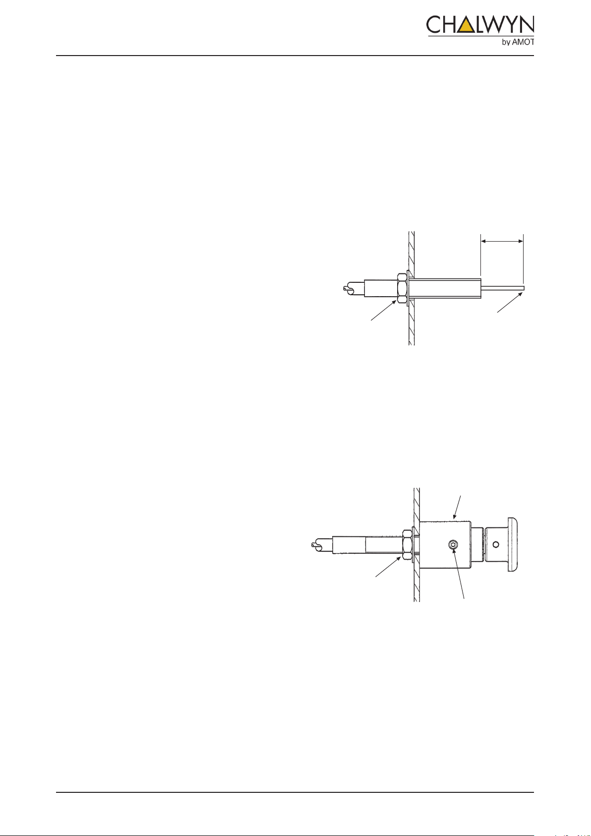
Cable lock nut
wound fully back
Check end of
inner is burr free
20 to 22mm
Cable lock nut
wound fully back
Check end of
inner is burr free
20 to 22mm
1. In the case of a naturally aspirated engine the
Chalwyn MPX shut down valve should generally
be fitted as close to the engine air intake manifold as possible. If an air intake flame trap is
also
fitted, the MPX valve must be installed upstream
(air cleaner side) of the flame trap.
2. To avoid excessively high intake air temperatures at the MPX valve when fitted to a turbocharged engine, it may be necessary to fit the
valve either upstream of the turbocharger or
downstream of the intercooler (where fitted).
Again, if an air intake flametrap is also installed,
the valve must be fitted upstream of the flametrap.
3. Where more than one MPX valve is fitted to an
engine, as in the case of an engine with multiple
intake pipes, a common pneumatic supply to the
valves should be used to ensure that all valves
close simultaneously.
4. The MPX valve may be installed either horizontally or vertically. Air flow may be in either
direction through the valve. Ensure easy and
safe access to the valve reset lever and, where
applicable, manual stop control. If the valve is
fitted with a cable operated manual stop ensure
a reasonably straight run for the cable.
5. If hose adaptors are used, the mating hose
should be of a reinforced type, provide adequate
support for the valve and prevent excessive
vibration. If necessary, additional support brackets mounted from the engine should be considered.
8. For valves with the “Push” button cable operated manual shut down, drill a Ø10mm (3/8”
clearance) hole through the bulkhead (or bracket) to which the stop button is to be mounted.
Pass cable end through hole. With the MPX
valve in the latched open position check that,
with the cable inner pressed hard back into the
cable outer, between 20mm and 22mm of the
inner shows.
.
With the MPX valve still latched open, use
a 2mm A/F hexagon key to release the cable
grip screw in assembly RBP-100 to enable the
assembly to be fully screwed onto the cable
outer.
Then tighten the cable locknut onto the back
face of the bulkhead. Finally, fully tighten the
cable grip screw (see diagram below).
RBP-100
6. Particular care must be taken to ensure the
7. Any engine crankcase breather connections
5
integrity of the intake pipework between the
Chalwyn valve and intake manifold. Ideally
metal pipework should be used and any gaps
kept as short as possible, (taking into account
any relative movement) and closed by reinforced
hose. The possibility of a hose collapse on closure of the shut down valve must be avoided.
into the intake system between the MPX valve
and engine, or any internal crankcase breather
arrangement venting directly into the engine
intake ports must be sealed and replaced by
an external breather system venting either to
atmosphere or to the intake system upstream of
the shut down valve. External breather system
kits for various engine types are available from
Chalwyn.
MPX DIESEL ENGINE SHUTDOWN VALVES
CE236 (9)
Lock nut - tighten
after fully screwing
RBP-100 onto the
cable outer
Cable Grip Screw
T: +44 (0)1284 715739
Page 6
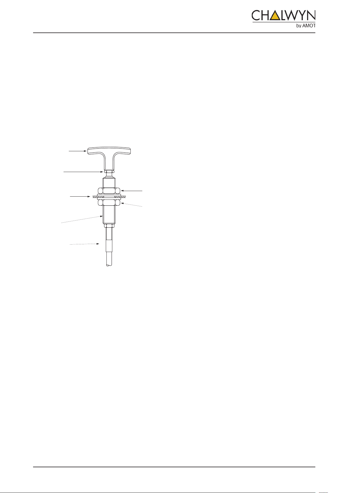
9. For values with the “pull” handle cable
‘T’ HANDLE
HANDLE
LOCKNUT
STOP CABLE
UPPER
LOCK NUT
LOWER
LOCK NUT
HANDLE
BODY
BULKHEAD
MOUNTING
BRACKET
operated manual shut down, fit the ‘T’ handle
assembly RTD-100 through a suitable Ø20mm
(3/4”dia) hole in a bulkhead or mounting bracket
as follows. Release the handle locknut. Remove
the handle, handle locknut and upper locknut and
washer. Thread handle body through the bulk-
head/bracket. Refit upper locknut and washer.
Adjust lower and upper locknuts to position handle
and tighten. Refit handle locknut and handle.
Tighten locknut.
10. Connect shut down air supply using the 1/4NPT
tapping on valve. Means must be provided to
release any trapped air pressure at the MPX
valve connection when the air pressure shut
down signal is not being applied.
11. Prior to putting the engine into service the checks
listed under “Monthly” maintenance should first
be completed (see page 7).
6
MPX DIESEL ENGINE SHUTDOWN VALVES
CE236 (9)
T: +44 (0)1284 715739
Page 7

OPERATION
Prior to starting the diesel engine the MPX valve must be latched in the open position by rotating the reset
lever clockwise as far as possible. Once latched, the reset lever and valve will remain in the latched open
position until released by application of air pressure or by operating the stop button.
After an emergency shut down by air pressure or by operating the stop button, the MPX valve must always
be reset before re-starting the engine.
After a normal (diesel fuel only) shut down, the MPX valve will not require reset.
MAINTENANCE
MONTHLY:
Check that all intake system fasteners and any
associated support bracket fasteners are securely
tightened.
Check that any intake system hoses between the
MPX valve and engine are free from damage and
suitable for further service.
Run engine, preferably at or just above low idle
speed. Apply shut down air pressure signal to
valve. Check that the valve reset lever immediately
rotates to the valve closed position and the engine
stops within a few seconds.
Run engine, preferably at or just above low idle
speed. Operate the manual shut down control.
Check that the valve reset lever immediately rotates
to the valve closed position and the engine stops
within a few seconds.
Notes:
The engine must not be put back into service until
any problems identified by the above checks are
rectified.
7
MPX DIESEL ENGINE SHUTDOWN VALVES
CE236 (9)
T: +44 (0)1284 715739
Page 8

Chalwyn by AMOT
[email protected]
www.chalwyn.com
A division of Roper Industries Limited
UK
Western Way
Bury St Edmunds
Suffolk, IP33 3SZ
Tel: +44 (0)1284 715739
Fax: +44 (0)1284 715747
USA
8824 Fallbrook Drive
Houston
TX 77064
Tel: +1 281 940 1800
Fax: +1 713 559 9419
Canada
3230 97 Street
Edmonton
Alberta, T6N 1K4
Tel: +1 780 465 4429
Fax: +1 780 469 6275
CHALWYN RESERVES THE RIGHT TO UPDATE THIS PRODUCT SPECIFICATION WITHOUT PRIOR NOTICE.
 Loading...