

Page 1
Installation Guide ALF80
Discreet SubwooferV1.4 April 2015
Page 2

Caution: Read this before operating your unit
01
To ensure optimal performance, please read
this guide carefully and keep in a safe place
for future reference.
02
Install this product in a cool, dry, clean place away from direct sunlight and heat sources,
vibration, dust and moisture.
03
Do not expose this unit to sudden
temperature changes or locate it in an
environment with high humidity. This is to
prevent condensation forming inside which
may cause damage to the unit.
WARNING:
No attempt should be made to install this product within existing building structures unless you are certain
no electric cables, water pipes, gas pipes or supporting joists will be cut through.
04
Do not clean this unit with chemical solvents
as this may damage the finish. Use a clean,
dry or damp cloth.
05
Do not attempt to modify or repair the unit.
Contact your distributor or manufacturer if a
fault should occur.
06
Ensure that any fixing structures will support
the weight of this product.
07
Do not modify the length of the port by
cutting it or by extending it using additional
tubing, or flexible pipes. Doing so will
seriously compromise the acoustic
performance of thre product.
Contents
01
Included in the carton
02-3
Using the Adjustable Port System
04
Positioning the ALF80
05
Positioning the ALF80 (Diagram)
06
Connection Options (Passive 2. 1)
07
Connection Options (Passive 2. 2)
08
Connection Options (Active 2. 1)
09
Connection Options (Active 2. 2)
1 0
Connection Options (Home Cinema)
1 1
Setup Tips
1 2
Specifications
13
Dimensions
Page 3
01
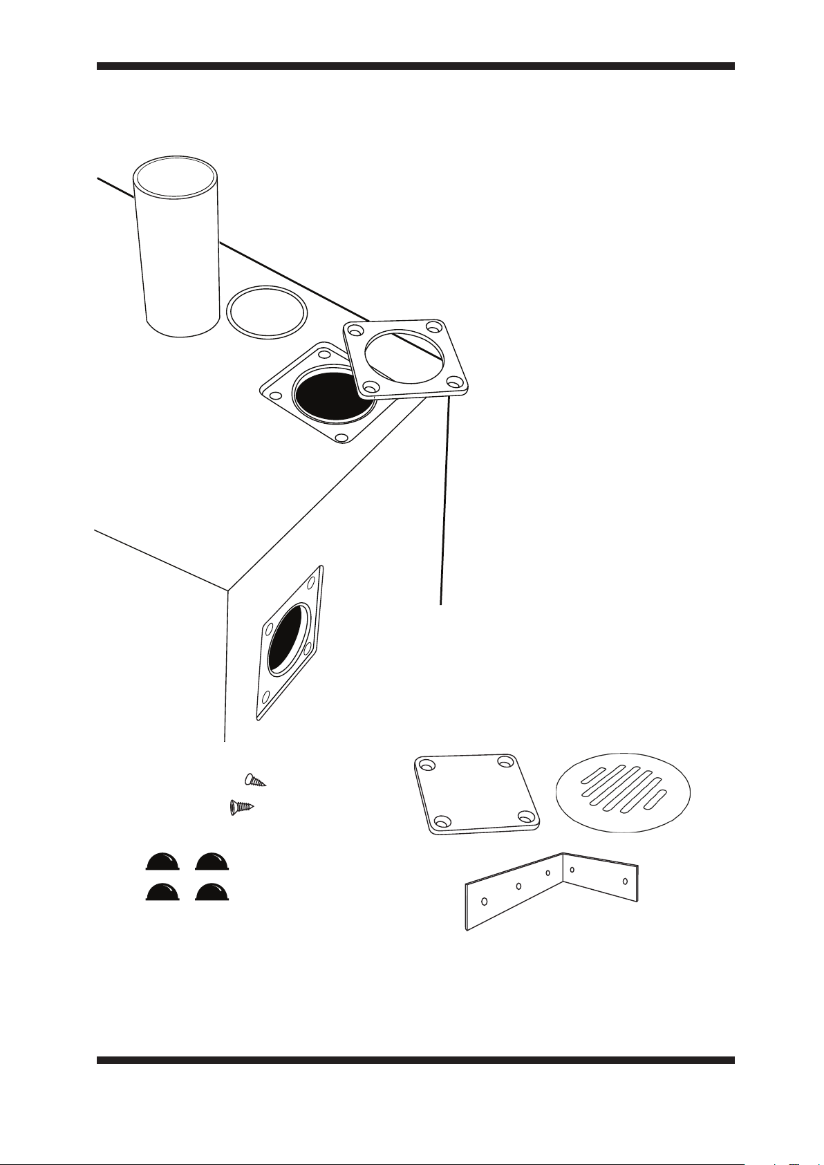
Included in the carton
Parts:
01
02
03
01 Port x1
02 Rubber O-ring x1
03 Port Plate x1
04 Cabinet x1
05 20 x Bracket Screws
(4x20mm)
06 Port Plate Blank
07 Rubber feet x4
08 Bracket x4
09 Port Cover Plate
04
09
06
05
20x
(4x20mm)
07
08
Please contact your dealer if any of the above parts are missing or you require spares.
WARNING: TAKE CARE TO NOT DROP OBJECTS THROUGH THE PORT
HOLES AND INTO THE ALF80 ENCLOSURE.
Page 4
02
Using the Adjustable Port System
The ALF80 features a unique port system allowing for greater flexibility when positioning and
concealing the product.
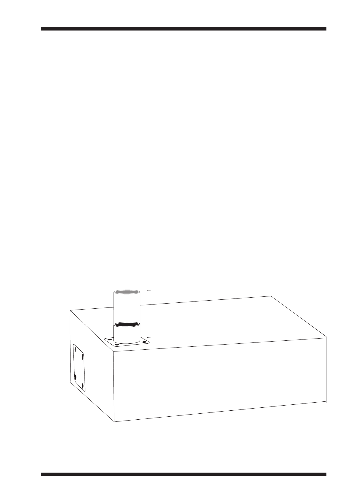
There are two optional positions where the port can be connected to the ALF80 cabinet. An aluminium
plate (port plate) and a rubber o-ring provide an air tight seal around the port. A similar blanking plate
is used to cover and seal the unused port hole.
To remove the port and blanking plates use a number 3 Hex screwdriver to remove the four fixing
screws. Then remove the plate from the cabinet taking care not to drop the o-ring through the port
openings.
To adjust the amount the port protrudes from the ALF80 cabinet, remove the screws along with the
port plate and pull/push the port by gripping the inside surface. Ensure the o-ring is correctly positioned
in its rebate before re-securing the port plate and make sure the port is absolutely firm. If it appears
loose, check the o-ring has not dropped through the opening.
Top Position
This port position can be useful if you need to stand the ALF80 on its end (connection terminal facing
upward), or when locating it in a ceiling void, port firing downward.
MAX 110mm
Page 5
03
Using the Adjustable Port System
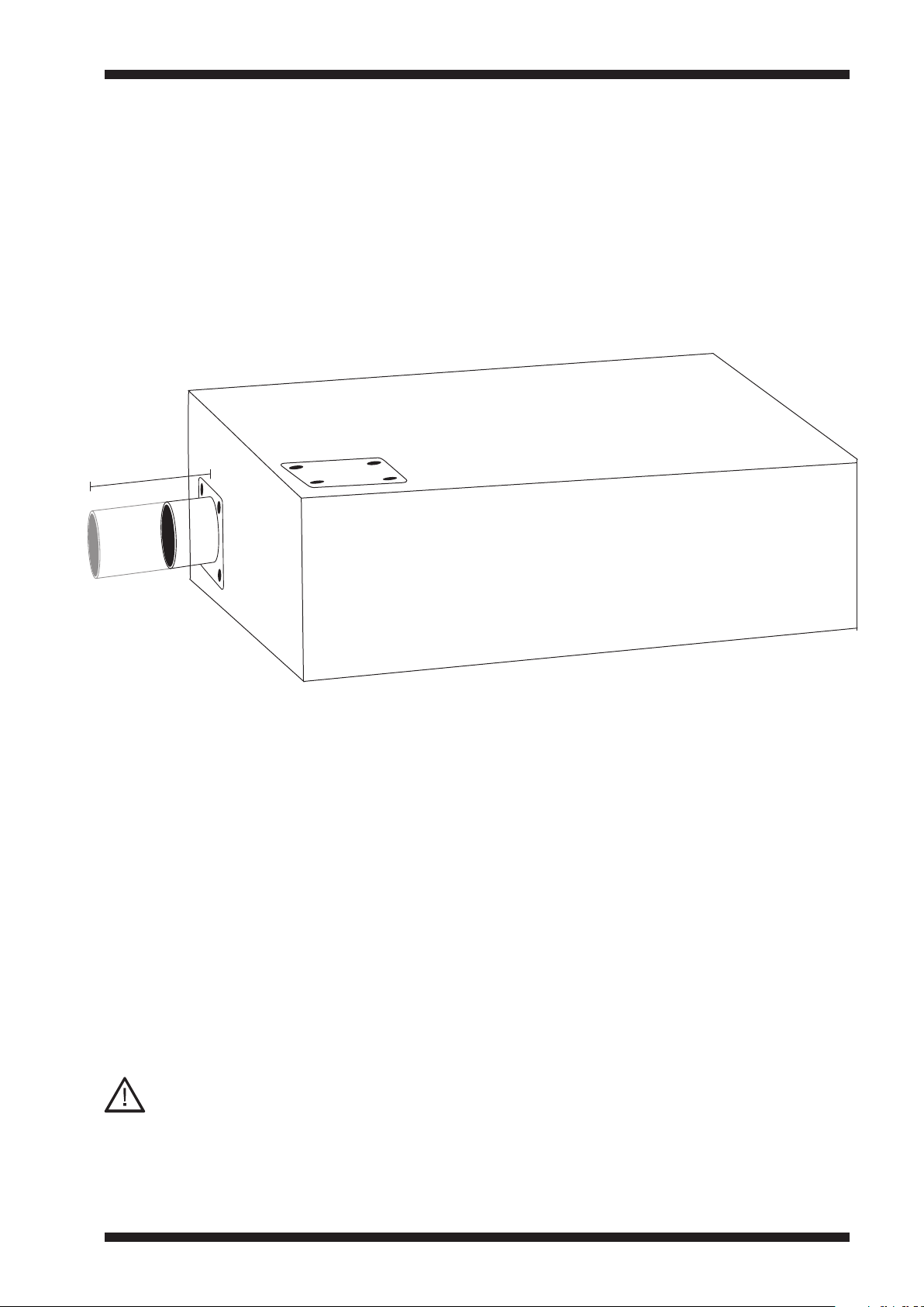
End Position
This port position is useful when the ALF80 is located behind a kickboard, or underneath a sofa.
MAX 110mm
Important notes:
ALWAYS loosen the four screws in the port
01
plate before adjusting the port.
The blanking plate MUST always be screwed
02
down over the port opening that is not in use.
Be sure to tighten both the port plate and the
03
blanking plate. Never over-tighten the screws.
Use ONLY the supplied screws to fix the port
04
and blanking plates.
Contact your dealer if spares are required.
DO NOT modify the length of the port by cutting it, or by extending it
using additional tubing, or flexible pipes. Doing so will seriously
compromise the acoustic performance of the product.
Ensure the rubber o-ring is correctly in
05
position around the port and sitting within the
circular rebate.
To release the blanking plate from its
06
position, it may be necessary to push it from
behind from within the cabinet. This can be
done via the other port opening once the
port is removed.
Page 6

04
Positioning the ALF80
Free Standing
The ALF80 can be positioned anywhere within a room and in any orientation. A location near the
corner of a room will give the most bass output however it is important to allow the bass port to
breathe. Do not place any solid objects closer than 50mm (2”) directly in front of the port. Adhere the
supplied rubber feet to the cabinet, this will protect the product from dirt and scratches when
positioned on the floor.
Fixing Brackets
Use the supplied brackets to secure the ALF80 to a solid structure. Use only the supplied, 12.3mm
screws to fix the brackets to the cabinet. Never use longer screws as these may damage the unit’s
internal components. Ensure the brackets are not fixed over the port plate, blanking plate or connection
terminal.
Concealed Placement
The ALF80 can be placed within furniture, behind wall panelling or even within a ceiling cavity.
Whatever structure you install the ALF80 inside, it is important to create a suitable hole for the port to
protrude through allowing it to breathe into the listening room.
Use the brackets and screws provided to secure the ALF80 within the structure.
In-Ceiling
The illustration on the next page shows how the brackets supplied can be used to fix the ALF80 to a
ceiling joist.
Notice the port protrudes from the cabinet - this allows it to then protrude through a suitable hole cut in
the plasterboard ceiling layer.
Page 7
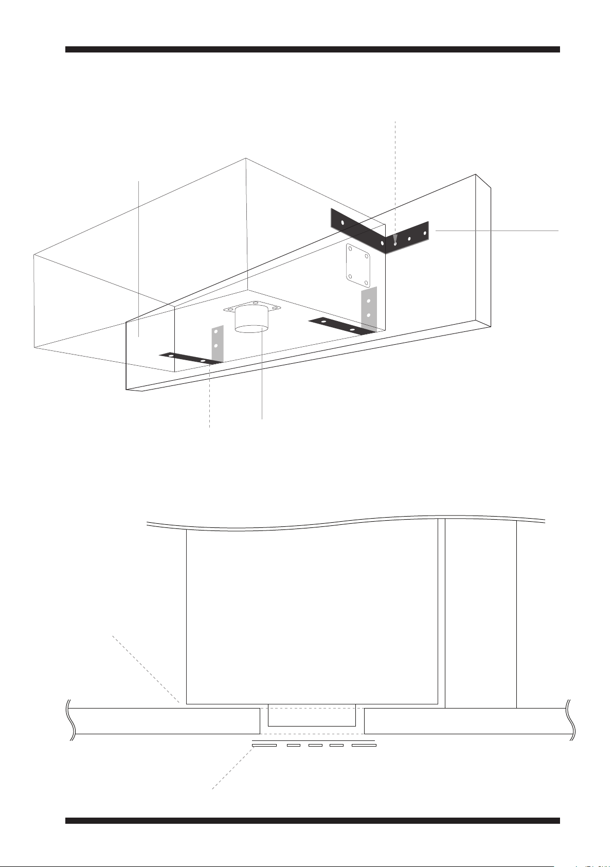
05
Positioning the ALF80 (Diagram)
In-Ceiling cont.
Ceiling Joist
12.3mm screws
into ALF40
21mm screws
into joist
Brackets
Port
Detail view
min 10mm
max 80mm gap
Plasterboard Ceiling
ALF80
Ceiling Joist
Cover Plate
Page 8
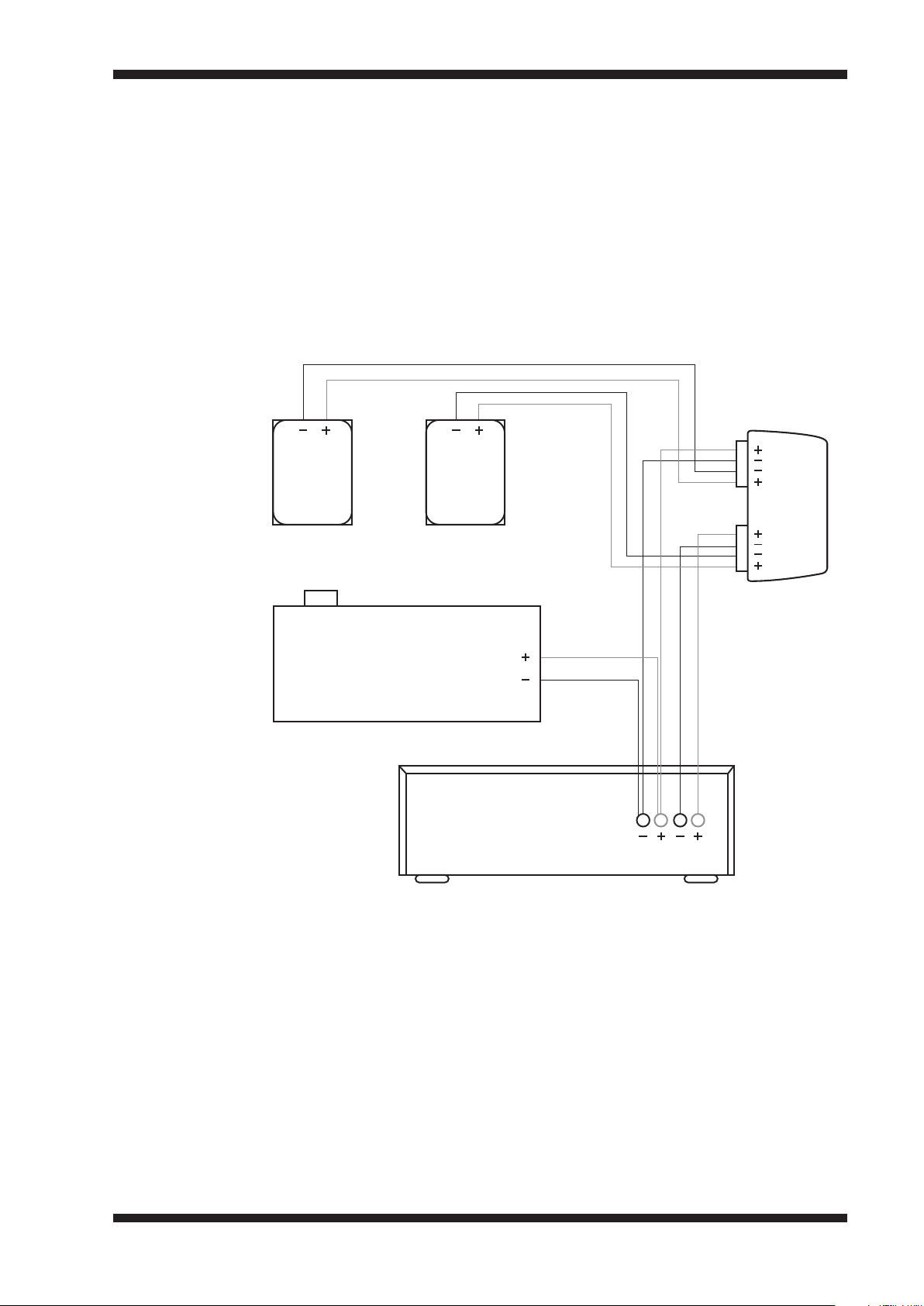
06
Connection Options (Passive 2.1)
The ALF80 has been optimised to work with the Amina Evolution and iQ Series Invisible speakers.
The following examples illustrate its use with these series of speakers. The ALF80 is designed so it can
be connected in parallel with AIW150i, AIW350i, AIW550i, iQ1 and iQ3.
Passive Stereo 2. 1 : AIW150i / AIW350i pair + ALF80
CH 1
APU150 /
APU350
L R
CH 2
ALF80
Stereo Amplifier
L R
Note: Amplifier must be 4 Ohm stable.
In this scenario, one of the amplifier channels (left or right) is used to drive the ALF80 and one of the
invisible speakers together in parallel. It is assumed bass frequencies are mixed in mono on most
program material, however for orchestral music better performance will be obtained with the ALF80
connected to the right channel of the amplifier.
The output of an ALF80 in most situations will match a pair of AIW150i or AIW350i speakers (2x ALF80
may be necessary to match a pair of AIW350i or AIW550i in a large room).
Note:
You may need to adjust the amplifier’s balance control to obtain an equal output from the invisible
speakers.
Page 9
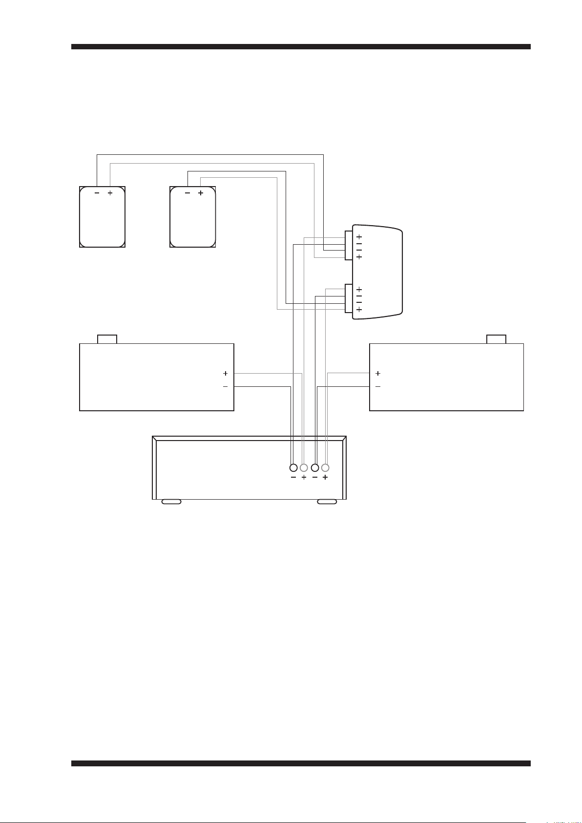
07
Connection Options (Passive 2.2)
Passive Stereo 2. 2: AIW550i pair + 2x ALF80
AIW550iAIW550i
CH 1
L R
ALF80
Stereo Amplifier
Note: Amplifier must be 4 Ohm stable.
APU550
CH 2
ALF80
L R
For systems using a pair of AIW550i speakers, a pair of ALF80’s may be necessary. In large rooms
greater than 75m
AIW550i.
2
, each channel of the stereo amplifier drives one ALF80 in parallel connection with an
Page 10
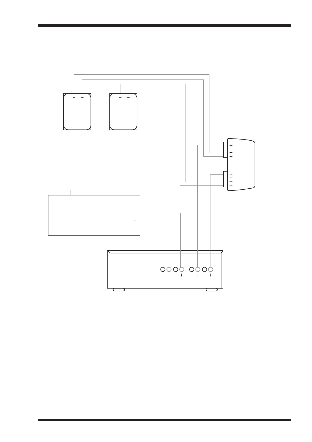
08
Connection Options (Active 2.1)
Active Stereo 2. 1: AIW150i/ AIW350i/ AIW550i/ iQ1/ iQ3 and ALF80
L R
CH 1
APU
CH 2
ALF80
Multi-channel
Amplifier
L RL R
CH3 CH4CH1 CH2
By connecting a single ALF80 to its own amplifier channel, its output (relative to the invisible speaker
pair) can be set optimally. In larger rooms care should be taken not to adjust the relative output of a
single ALF80 too high. This may result in the unit reaching its mechanical limits well before that of the
accompanying invisible speakers. In a larger room (>75m
2
) a second ALF80 may be required.
Page 11
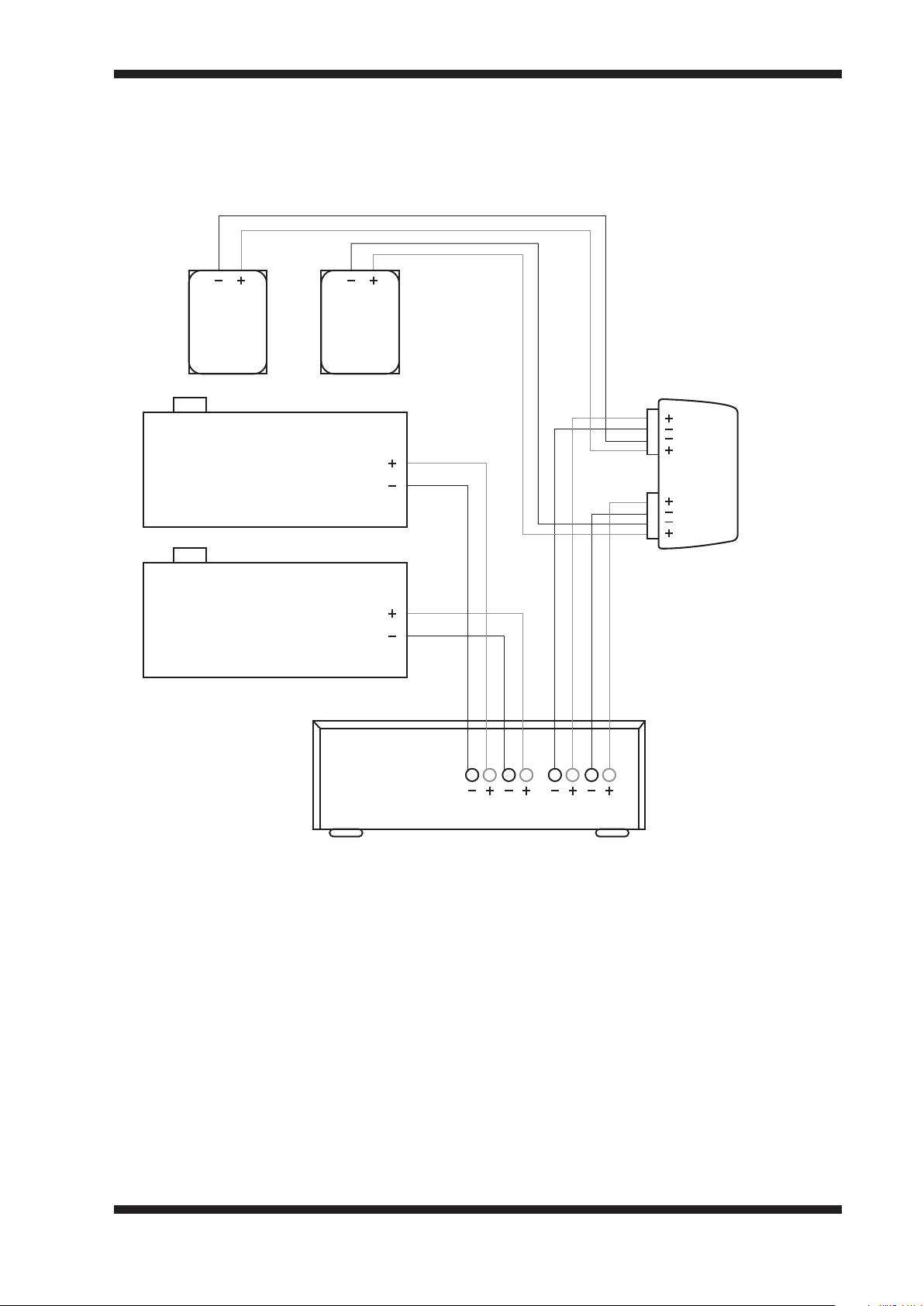
09
Connection Options (Active 2.2)
Active Stereo 2. 2: AIW550i pair + 2x ALF80
AIW550i
L R
ALF80
ALF80
AIW550i
Multi-channel
Amplifier
CH 1
APU550
CH 2
L RL R
CH3 CH4CH1 CH2
For systems using a pair of AIW550i speakers in rooms larger than 75m
In this scenario the amplifier will need four independent channels.
2
two ALF80’s will be necessary.
Page 12
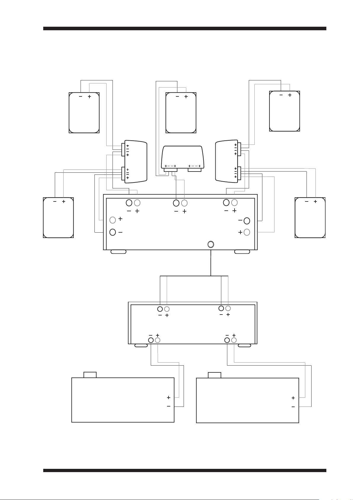
1 0
Connection Options (Home Cinema)
5.1 Cinema system. 5x AIW550i + 2x ALF80
AIW550i
Surround L
AIW550i
L
SL
CH1
CH 2
APU550
CH 1
FL
CH2
AIW550i
Centre
APU550
CH 3
Centre
CH3
AVR
Sub Out
CH 4
APU550
CH 5
FR
CH4
Y-Splitter
SR
CH5
AIW550i
R
AIW550i
Surround R
ALF80
L
2 Channel
Amplifier
R
RL
ALF80
Page 13

1 1
Setup Tips
When setting up any of the above system
01
scenarios, it is advised to experiment with
connecting the ALF80 in reverse phase with
respect to the Evolution series speakers.
Often the reverse-phase connection results in
better integration and slightly higher sound
pressure level through “cross-over” region.
Using pink noise can be a good way of
judging the difference between the in-phase
and reverse-phase connections.
To avoid unwanted vibrations, ensure the
02
ALF80 is fixed securely to a structure or, if
free standing, the supplied rubber feet are
used.
The supplied port cover plate can be used to
03
improve the appearance of the port when,
for example, the ALF80 is installed behind
plasterboard walls or ceilings. The plate is
supplied with acrylic transfer adhesive
already fitted; use the tab to assist removal of
the liner paper then press the plate firmly
into place. Please refer to the detail view on
page 5.
Alternative finishes can be applied to the
cover plate; for best results use water based
paints and primers.
Page 14

1 2
Specifications
Dimensions:
Weight:
Design:
605mm x 270mm x 156mm
4/5
(23
9.2Kg (20
” x 10
3/5
6/25
” x 6
lbs)
1/10
”)
Ported, acoustic bandpass with built in
protection circuit
Power Handling:
Nominal Impedance:
Frequency Response:
150W continuous
4 Ohms
39Hz - 140Hz (+/-6dB) 18dB/ octave
band-pass
Sensitivity:
Maximum Short term SPL:
Connection:
86dB 1m/1W *
108dB 1m/1W **
3-Way binding post
* Corrected nearfield port measurement.
** Corrected nearfield port measurement. Assumes no in-room boundary loading which in some cases
may increase SPL by as much as 6dB.
Limited Warranty:
The ALF80 is designed to operate reliably for many years. Correctly installed and in accordance with
these instructions, Amina warranties the ALF80 against defective materials and workmanship for a
period of one year.
Page 15
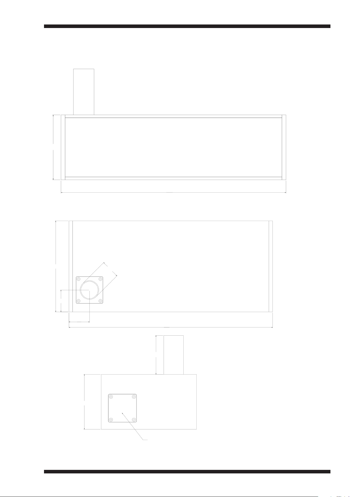
1 3
Dimensions
156mm
605mm
270mm
65mm
61mm
156mm
55.8mm
605mm
Max 110mm
Note:
Centre hole location of
port tube exactly the
same as other port.
Page 16

Amina Technologies Ltd
Cirrus House, Glebe Road
Huntingdon, Cambs, PE29 7DL England
T: +44 1480 354390
W: www.amina.co.uk / E: [email protected]
Copyright 2013
 Loading...