

Page 1
www.amico.com
Installation and Maintenance Manual
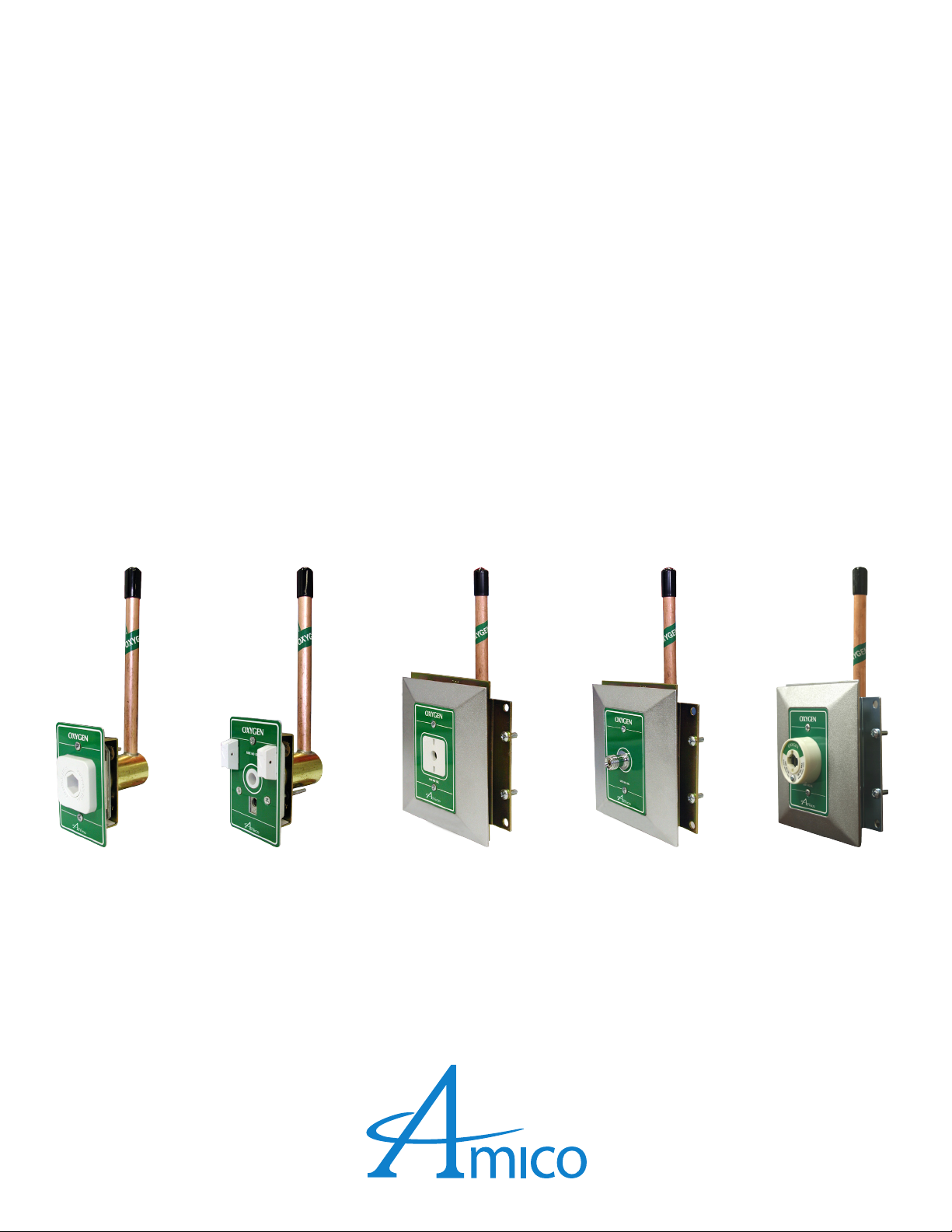
Medical Gas Outlets
DISS, Ohmeda, Chemetron, Puritan-Bennett &
Oxequip / MedStar Compatible
Puritan-Bennett
Compatible
Chemetron
Compatible
Compatible
DISS Ohmeda
Oxequip/ MedStar
Compatible
Page 2

Table of Contents
Product Description 3
Cleaning and Lubricating 4
Inspection and Testing 4
Installation & Dimensions 5-7
Wall Outlet 5
Ceiling Outlet 6
Console Outlet 6
Ceiling Column Outlet 7
Service 8-13
Latch-Valve Assembly - DISS 8
Latch-Valve Assembly - Ohmeda (compatible) 9
Latch-Valve Assembly - Chemetron (compatible) 10
Latch-Valve Assembly - Puritan-Bennett (compatible) 11
Latch-Valve Assembly - Oxequip/MedStar (compatible) 12
Rough-In Assembly - Wall and Console 13
Model Numbers 14-16
Latch-Valve Assembly 14
Rough-In Assembly 15
Complete Outlets 16
Gas Indexing 17
Replacement Components 18-23
Latch-Valve Assembly - Ohmeda (compatible) 18
Latch-Valve Assembly - Chemetron (compatible) 19
Latch-Valve Assembly - DISS 20
Latch-Valve Assembly - Puritan-Bennett (compatible) 21
Latch-Valve Assembly - Oxequip/MedStar (compatible) 22
Rough-In Assembly - Wall and Console 23
2 Amico Pipeline
Page 3

Product Description
The Amico Medical Gas outlet is composed of two separate modules: the “Rough-in assembly” and the “Latch-valve
assembly”. The “Rough-in assembly” is the same for all types (DISS, Ohmeda, Chemetron, Puritan-Bennett or Oxequip/
MedStar), while the “Latch-valve assembly” determines what type of adapter the outlet will accept.
The “Rough-in assembly” consists of a brass machined body that incorporates a spring loaded check assembly. A 1/2”
OD copper pipe is silver brazed into the body for external pipeline connections. The brass body and pipe assembly are
inserted into a gas specic plate. The wall outlets can be ganged together at 5” [127mm] centers (see page 5). This makes
for a nished assembly that looks like one complete panel of outlets. The “Rough-in assembly “has a color coded label
on the front plate and the copper pipe, so that the installer can easily identify the gas that the copper pipe should be
connected to. The “Rough-in assembly” incorporates a check valve that allows the “Latch valve assembly” to be removed
for service, without requiring the pipeline to be shut down. The “Rough-in assembly” has a DUAL pin gas specic indexing
arrangement to prevent the wrong “Latch valve assembly” from being plugged into the “Rough-in assembly” (see page
17).
The “Latch-valve assembly” is manufactured in ve dierent models: DISS, Quick connect Ohmeda compatible, Quick
connect Chemetron compatible, Quick connect Puritan-Bennett compatible or Quick connect Oxequip/MedStar
compatible. The DISS “Latch-valve assembly” is permanently riveted together, so that the gas specic components cannot
be taken apart, to ensure they remain gas specic. All the servicing on the DISS outlet is done inside the connector. On the
Quick connect models the connector plate can be removed for additional O-ring servicing, but is still gas specic since the
gas specic parts are permanently riveted together. The “Latch-valve assembly” consists of: a connector with an integral
check valve, an indexing block complete with indexing pins, a color coded gas front plate and a chrome frame. The “Latchvalve assembly” is inserted into the “Rough-in assembly” and secured screws.
CAUTION: DO NOT overtighten the Latch Valve Mounting screws! Distortion of the Latch valve can occur.
The quick connect models are compatible with the Ohmeda Diamond, the Oxequip/MedStar, the Chemetron, and the
Puritan-Bennett quick connect adapters. Only the corresponding type of adapters can be used with the quick connect
outlets. The DISS outlet conforms to the CGA Pamphlet V-5 standards. Since the “Rough-in assembly” is the same for all
models of “Latch-valve assemblies”, the outlet can easily be converted from one type to another by simply replacing the
“Latch-valve assembly”.
www.amico.com 3
Page 4

Cleaning and Lubricating
The Amico Outlets are factory cleaned for oxygen service. Exposed surfaces of the outlet may be cleaned with a mild
detergent solution or wiped with a disinfectant commonly used in patient rooms, that is compatible with plastics,
anodized aluminium and die cast zinc. Lubricate elastomer seals sparingly with a silicone lubricant that is oxygen
compatible. DO NOT USE OIL.
Inspection and Testing
Medical Gas Outlets should be inspected periodically or at least once a year. The test should be in accordance with NFPA
99 “Gas and Vacuum systems” .
Test for Leaks:
Ensure that no leaks exists, with or without the adapter inserted.
Test for Indexing:
Only a mating gas specic adapter should insert smoothly into the outlet, latch and be retained.
Test for Flow:
• Gas Outlets: 120 l/min (4.2 scfm) @ 345 kPa (50 psi), maximum allowable pressure drop is 28 kPa (4 psi).
• Nitrogen Outlet: 400 l/min (14.1 scfm) @ 1,250 kPa (180 psi), maximum allowable pressure drop is 70 kPa (10
psi).
• Vacuum Outlet: 30 l/min (1.1 scfm) @ 54 kPa (16 inHg), maximum allowable pressure drop is 13 kPa (4 inHg).
Refer to the appropriate standards for the proper way of performing the ow test.
Note:
The Amico medical gas and vacuum outlets meet and exceed these requirements at the time of manufacture.
However piping source capacity, sizing and restrictions may prevent outlets from attaining these values.
4 Amico Pipeline
Page 5
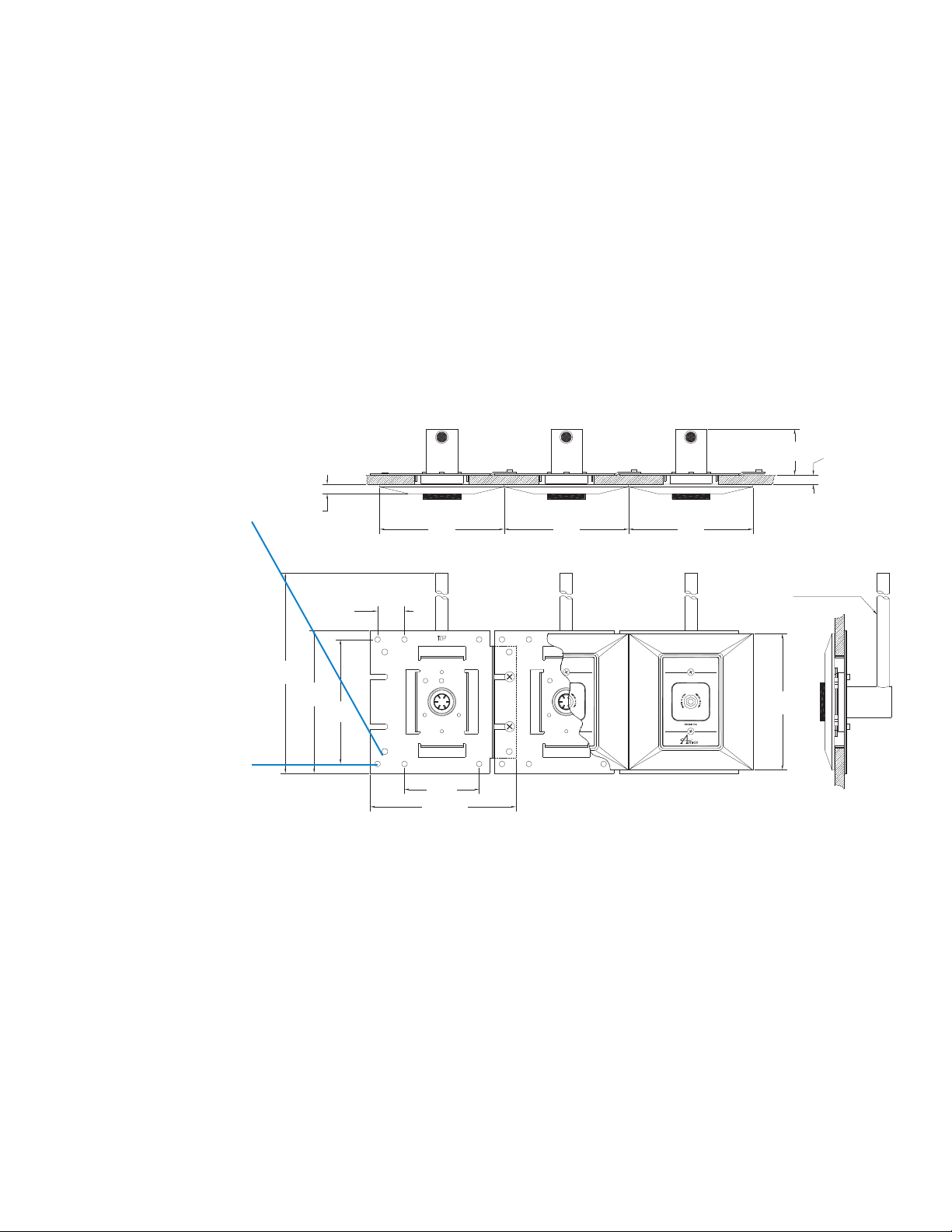
Installation and Dimensions
Wall Outlets
DISS, Ohmeda compatible, Chemetron compatible, Puritan-Bennett and Oxequip/MedStar compatible
When wall outlets are ganged
together, ensure that they
are 5” from center to center.
DO NOT let the notches on
the mounting plate pass the
adjacent holes on the next
mounting plate.
3/8”
[10]
1-1/16”
[27]
5”
[127]
5”
[127]
5”
[127]
1/2" [12.7 mm] O.D. (3/8” nominal) type "K"
copper pipe, rotates 360 deg.
for entry from any angle
1 7/8”
[48 ]
Inch
[mm]
Wall thickness
may vary from
3/8" to 1"
10mm to 25mm]
[
Do not bury the outlet during
the drywall and plaster application. Ensure that the cover
over the outlet is in place until the “Latch-valve assembly”
can be installed.
10”
[254]
5-3/4”
[146]
5”
[127]
OXY
3” [76]
5-27/32” [ 148]
OXYGENYGEN
OXY
NOTE:
Amico recomends that you have a blank space
between outlets and slides.
Maximum 3 outlets may be ganged together
without additional support.
5-1/2”
[140]
www.amico.com 5
Page 6

without additional support.
5
Installation and Dimensions
Ceiling Outlets
DISS, Ohmeda compatible, Chemetron compatible, Puritan-Bennett and Oxequip/MedStar compatible
Inch
[mm]
When wall outlets are ganged
together, ensure that they
are 5” from center to center.
DO NOT let the notches on
the mounting plate pass the
3/8”
[10]
1-1/4”
[32]
[127]
5”
[127]
5”
[127]
5”
1-7/8”
[48]
Wall thickness
may vary from
3/8” to 1”
[10mm to 25 mm]
adjacent holes on the next
mounting plate.
MEDVAC
Do not bury the outlet during
-3/4”
[146]
[127]
5”
5-1/2”
[140]
the drywall and plaster application. Ensure that the cover
over the outlet is in place until the “Latch-valve assembly”
can be installed.
3”
[76]
5-27/32”
[148]
NOTE:
Amico recommends that you have a blank space
between outlets and slides.
Maximum 3 outlets may be ganged together
Console Outlets
DISS, Ohmeda compatible, Chemetron compatible, Puritan-Bennett and Oxequip/MedStar compatible
inch
[mm]
TOP VIEW
1/2" [12.7 mm] O.D. (3/8” nominal) type "K"
copper pipe, rotates 360 deg.
for entry from any angle.
FRONT VIEW
BACK
ASSEMBLY
8-7/8"
[225]
3-9/16"
[91]
1-13/16"
[46]
3-9/32"
[83]
OXY
FRONT VIEW
FRONT
ASSEMBLY
OXYGEN
OXY
2-7/16"
[62]
3-3/4"
[95]
SIDE VIEW
FRONT
ASSEMBLY
2-7/16"
[62]
SIDE VIEW
6 Amico Pipeline
Page 7

Installation and Dimensions
Ceiling Column Outlets
DISS, Ohmeda compatible, Chemetron compatible, Puritan-Bennett and Oxequip/MedStar compatible
1/2" [12.7 mm] O.D. (3/8” nominal) type "K"
copper pipe, rotates 360 deg.
for entry from any angle.
9-1/4"
[235]
inch
[mm]
FRONT VIEW
FRONT
ASSEMBLY
OXYGEN
OXY
2-7/16"
[62]
3-3/4"
[95]
SIDE VIEW
FRONT
ASSEMBLY
SIDE VIEW
2-7/16"
[62]
3-9/16"
[91]
FRONT VIEW
BACK
ASSEMBLY
OXY
1-13/16"
[46]
3-9/32"
[83]
On all outlets (wall and console) the connecting pipe can swivel a full 360 deg. for easy connection to the gas pipe.
When soldering the pipe connection take care not to heat up the body, since that could damage the secondary check
valve.
It is very important to keep the protective cover (wall outlets only) in place during construction, to ensure that no debris
or dirt get into the outlet.
When installing the “Latch-valve assembly”, remove the protective cover and inspect for dirt or debris in the outlet body.
Clean out the contaminants, if required.
The “Latch-valve assembly” should slide in smoothly into the “Rough-In assembly”, if not, check that there is no damages to
the indexing pin arrangements. If the indexing pins are bent or damaged, replace the “Latch-valve assembly”.
DO NOT PRESSURE TEST THE PIPELINE OVER 100 PSI [690 kPa] IF THE “LATCH-VALVE ASSEMBLY” HAS BEEN
INSTALLED.
All “Rough-in assemblies” can be pressure tested up to a maximum of 200psi without the “Latch-valve assembly” attached
to it.
All “Latch-valve assemblies” with the exception of Nitrogen DISS have a Maximum pressure rating of 100 PSI [690 kPa]. The
Nitrogen D I S S has a maximum pressure rating of 200 psi [1,380 kPa].
After installation, perform the test on page 1.
www.amico.com 7
Page 8

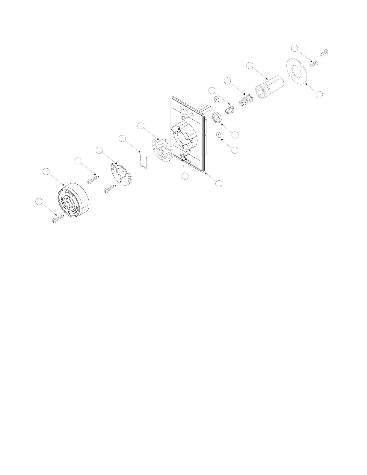
Service
Before performing any maintenance on the Outlet, the appropriate hospital maintenance or engineering personnel
should be notied. The “Latch-valve assembly” can be removed without interrupting the service, but when servicing
the “Rough-In assembly” the supply pressure has to be shut o.
Latch Valve Assembly DISS
23
22
20
17
13
12
16
21
Note:
Latch-Valve Assembly Model Numbers see Page 14
15
Complete Outlet Model Numbers see Page 16
11
Repair Kit Model Numbers see Page 20
1. Unscrew the two retaining screws (12) until the Latch Valve Assembly (11) can be removed from the outlet.
2. Remove the O-Ring seal (16) from the front and replace (NOTE: There is no O-Ring for Oxygen, Medical Air and
Carbon Dioxide).
3. Remove the retaining ring (23) using appropriate pliers. Remove the valve stem (17), O-Ring seal (20), primary
check valve (21) and spring (22). Inspect the items for wear or damage and replace if needed. Replace the O-Ring
(20).
4. Re-install all internal components and lock in place with the retaining ring (23).
5. Re-install the Latch Valve Assembly into the outlet. Coat the connector (15) with a thin coat of oxygen compatible
silicone lubricant to aid insertion. Tighten down the retaining screws (12), DO NOT over tighten, as this could
damage the Latch Valve.
6. Connect a gas specic adapter to the outlet. The connection should be smooth and hand tightening of the nut
should be sucient to allow the gas to ow without leakage. If not, replace the entire Latch Valve Assembly (11).
8 Amico Pipeline
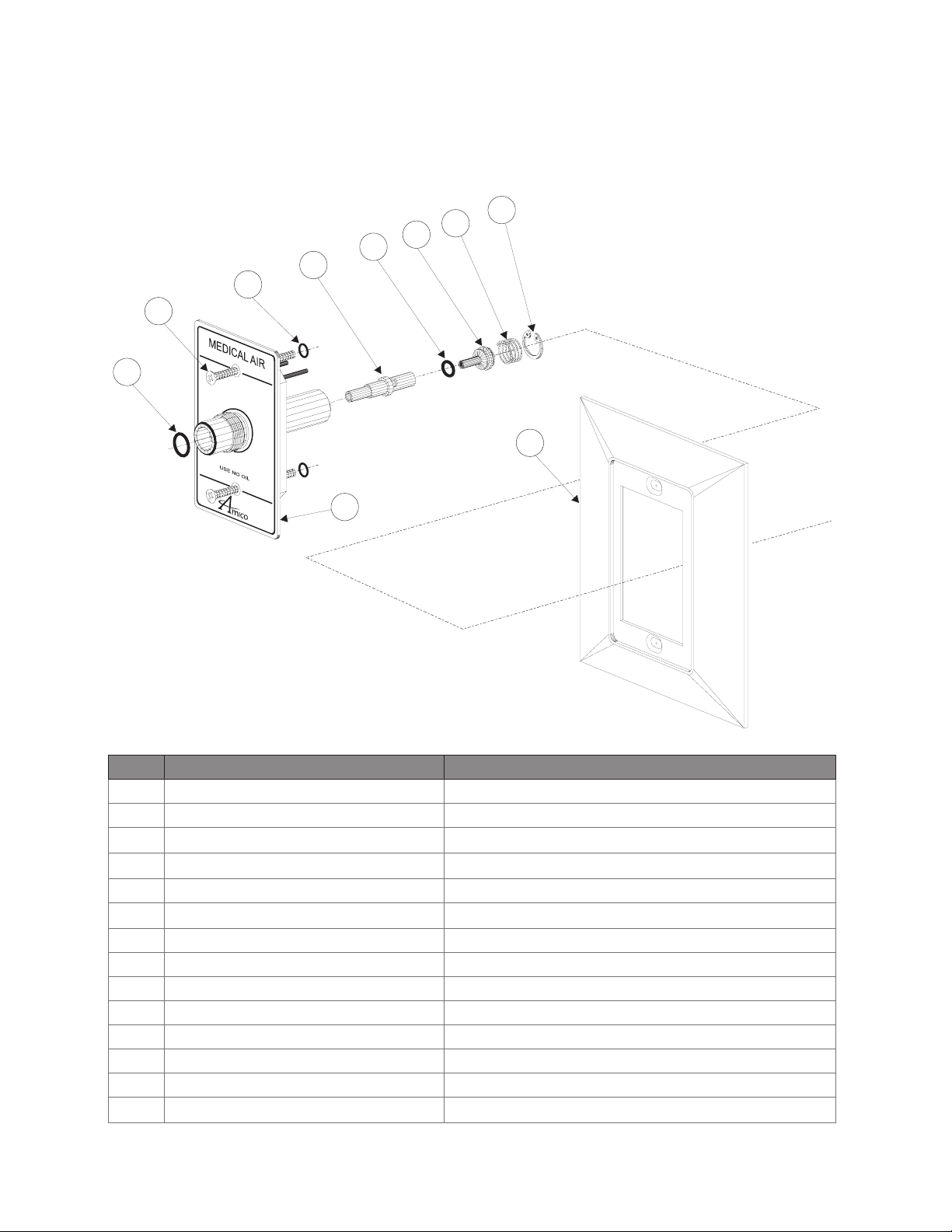
Page 9

Latch Valve Assembly Ohmeda (Compatible)
23
22
21
20
19
18
17
13
12
Note:
Latch-Valve Assembly Model Numbers see Page 14
25
24
USE NO OIL
15
Complete Outlet Model Numbers see Page 16
16
Repair Kit Model Numbers see Page 18
14
11
1. Unscrew the two retaining screws (12) until the Latch Valve Assembly (11) can be removed from the outlet.
2. Remove the four screws (25) holding the connector retaining plate (24) in place. Remove the plate.
3. Remove the connector (17) from the valve assembly.
4. Remove the U-spring (14), inspect for wear or damage, re-install the U-spring.
5. Remove the at washer (15) and connector O-Ring (16) from the front of the connector. Inspect the items for wear
or damage and replace the O-Ring seal (16).
6. Remove the retaining ring (23) using appropriate pliers. Remove the dust cap (18), dust cap spring (19), O-Ring seal
(20), primary check valve (21) and spring (22). Inspect the items for wear or damage and replace if needed. Replace
the O-Ring (20).
7. Re-install all internal components and lock in place with retaining ring (23). Insert the Connector (17) into the gas
specic body. Check that the U-Spring (14), at washer (15) and O-Ring (16) are in place. Re-install the connector
retaining plate (24) and secure with four screws (25), do not overtighten.
8. Re-install the Latch Valve Assembly into the outlet. Coat the connector (17) with a thin coat of oxygen compatible
silicone lubricant to aid insertion. Tighten down the retaining screws (12), DO NOT over tighten, as this could
damage the Latch Valve.
9. Connect a gas specic adapter into the outlet. The connection should be smooth and the adapter should lock and
remain in place allowing gas to ow. If not replace the entire Latch Valve Assembly (11).
www.amico.com 9
Page 10

Latch Valve Assembly Chemetron (Compatible)
23
22
21
20
19
18
17
12
LIOONESU
Note:
Latch-Valve Assembly Model Numbers see
Page 14
25
24
Complete Outlet Model Numbers see Page
16
11
1. Unscrew the three retaining screws (12) until the Latch Valve Assembly (11) can be removed from the outlet.
2. Remove the four screws (25) holding the connector retaining plate (24) in place. Remove the plate.
3. Remove the connector (17) from the valve assembly.
4. Remove the connector O-Ring (16) from the front of the connector. Inspect the items for wear or damage and
replace the O-Ring seal (16).
5. Remove the retaining ring (23) using appropriate pliers. Remove the dust cap (18), dust cap spring (19), O-Ring seal
(20), primary check valve (21) and spring (22). Inspect the items for wear or damage and replace if needed. Replace
the O-Ring (20).
6. Re-install all internal components and lock in place with retaining ring (23). Insert the Connector (17) into the gas
specic body. Check that the O-Ring (16) is in place. Re-install the connector retaining plate (24) and secure with
four screws (25), do not overtighten.
16
Repair Kit Model Numbers see Page 19
7. Re-install the Latch Valve Assembly into the outlet. Coat the connector (17), with a thin coat of oxygen compatible
silicone lubricant to aid insertion. Tighten down the retaining screws (12), DO NOT over tighten, as this could
damage the Latch Valve.
8. Connect a gas specic adapter into the outlet. The connection should be smooth and the adapter should lock and
remain in place allowing gas to ow. If not replace the entire Latch Valve Assembly (11).
10 Amico Pipeline
Page 11

Latch Valve Assembly Puritan-Bennett (Compatible)
20
18
17
16
P
R
E
S
E
S
S
E
T
L
O
E
R
12
R
E
O
L
T
E
S
S
E
S
E
R
P
USE NO OIL
Note:
Latch-Valve Assembly Model
Numbers see Page 14
19
Complete Outlet Model Numbers
see Page 16
Repair Kit Model Numbers see
11
14
15
Page 21
1. Unscrew the two retaining screws (12) until the Latch Valve Assembly (11) can be removed from the outlet.
2. Remove the two screws (20), holding the round retaining ring (19) in place. Remove the plate.
3. Remove the gas connector (18) from the valve assembly.
4. Remove the Body Seal (15) and Poppet (16) from the front of the Gas Connector (18). Inspect the items for wear or
damage and replace the Body Seal (15).
5. Remove the Gas or Vacuum Spring (17), to inspect for wear or damage. Re-install the Gas or Vacuum Spring.
6. Re-install all internal components into the Gas Connector (18). Check that the Gas or Vacuum Spring (17), Body Seal
(15) and Poppet (16) are in place. Re-install the round retaining plate (19) and secure with two screws (20), do not
overtighten.
7. Re-install the Latch Valve Assembly into the outlet. Coat the connector (18) with a thin coat of oxygen compatible
silicone lubricant to aid insertion. Tighten down the retaining screws (12), DO NOT over tighten, as this could
damage the Latch Valve.
8. Connect a gas specic adapter into the outlet. The connection should be smooth and the adapter should lock and
remain in place allowing gas to ow. If not, replace the entire Latch Valve Assembly (11).
www.amico.com 11
Page 12
Latch Valve Assembly Oxequip/MEDSTAR (Compatible)
21
20
18
17
16
10
9
15
19
8
7
6
7
12
Note:
14
11
Latch-Valve Assembly Model Numbers see Page 14
Complete Outlet Model Numbers see Page 16
Repair Kit Model Numbers see Page 22
1. Unscrew the two retaining screws (12) until the Latch Valve Assembly (11) can be removed from the outlet.
2. Locking Mechanism Repair
Unscrewing the rst screw (7) and remove item (6). Then unscrew the second set of screws (7), this will give you
access to items (8), (9) and (10). Inspect all three items for wear or damage, replace if needed.
3. Outlet Gas Connector Repair.
While holding the round retaining ring (19) in place, remove the two screws (20). Remove the retaining ring (19)
and gas connector (18). Then remove the Body Seal (15), the Poppet (16) and the Gas or Vacuum Spring (17).
Inspect for wear or damage, replace components if needed.
Re-install the Gas or Vacuum Spring (17), the Poppet (16) and the Body Seal (15) into the gas connector (18).
Re-install gas connector (18) and retaining plate (19), secure with two screws (20). DO NOT OVERTIGHTEN.
4. Re-install the Latch Valve Assembly into the outlet. Coat the connector (18) with a thin coat of Oxygen compatible
silicone lubricant to aid insertion. Tighten down the retaining screws (12), DO NOT over tighten, as this could
damage the Latch Valve.
5. Connect a gas specic adapter into the outlet. The connection should be smooth and the adapter should lock
and remain in place allowing gas to ow. If not, replace the entire Latch Valve Assembly (11).
12 Amico Pipeline
Page 13

Rough-In Assembly Wall and Console
OXYGEN
1
OXYGEN
2
Note:
Rough-in Assembly Model Numbers see Page 15
Complete Outlet Model Numbers see Page 16
Repair Kit Model Numbers see Page 23
3
4
5
6
7
8
CAUTION: Ensure that the supply pressure is shut o before performing service.
Inside the “Rough-in assembly” is a secondary check valve whose function is to shut o gas ow when the “Latch-valve
assembly” is removed. This seat/seal also prevents leakage around the latch valve connector. As the secondary seal
is only a static seal, it will rarely need replacement. However, if the seat/seal does need replacement, follow the following
procedure:
1. Ensure that no pressure exists in the line by depressing the secondary check valve (5).
2. Remove the retaining ring (8) from the inside of the outlet body. Use a small screwdriver to pull the end of the
ring towards the center and then pull the ring up and out.
3. Remove the washer (7), seat/seal (6), secondary check valve (5) and secondary check valve spring (4). Inspect
items for wear or damage and replace the seat/seal (6).
4. Re-install the spring (4), secondary check valve (5), seat/seal (6) and the washer (7). Insert the retaining ring (8)
into the slot and ensure that the whole ring is seated properly.
5. Turn on the pressure and check for leaks. Re-install the “Latch Valve assembly” and perform the inspection and
test on page 1.
www.amico.com 13
Page 14

Model Numbers
Latch-Valve Assemblies
Gas Service
DISS Wall
Latch-valve assembly:
Oxygen O-FASW-DI-U-OXY O-FASW-DI-E-OXY O-FASW-DI-F-OXY
Medical Air O-FASW-DI-U-AIR O-FASW-DI-E-AIR O-FASW-DI-F-AIR
MedVac O-FASW-DI-U-VAC O-FASW-DI-E-VAC O-FASW-DI-F-VAC
Nitrous Oxide O-FASW-DI-E-N2O O-FASW-DI-E-N2O O-FASW-DI-F-N2O
Nitrogen O-FASW-DI-E-NIT O-FASW-DI-E-NIT O-FASW-DI-F-NIT
Carbon Dioxide O-FASW-DI-E-CO2 O-FASW-DI-E-CO2 O-FASW-DI-F-CO2
WAGD/AGSS O-FASW-DI-U-WAG O-FASW-DI-E-AGS O-FASW-DI-F-AGS
DISS Console Latch Valve:
For DISS Console Latch Valve replace the “W” in the O-FASW-DI-L-GAS to “C”.
For example: USA DISS Oxygen = O-FASC-DI-U-OXY
English USA English ISO French ISO
Ohmeda compatible Wall Latch Valve:
For Ohmeda compatible Wall Latch Valve replace the “DI” in the O-FASW-DI-L-GAS to “QD”.
For example: USA Ohmeda Vacuum = O-FASW-QD-U-VAC
Ohmeda compatible Console Latch Valve:
For Ohmeda compatible Console Latch Valve replace the “W” in the O-FASW-QD-L-GAS to “C”.
For example: USA Oxygen = O-FASC-QD-U-OXY
Chemetron compatible Latch Valve:
For Chemetron compatible Wall Latch Valve replace the “DI” in the O-FASW-DI-L-GAS to “CH”.
For example: Chemetron USA Vacuum = O-FASW-CH-U-VAC
Chemetron compatible Console Latch Valve:
For Chemetron compatible Console Latch Valve replace the “W” in the O-FASW-CH-L-GAS to “C”.
For example: Chemetron USA Oxygen = O-FASC-CH-U-OXY
Puritan-Bennett compatible Latch Valve:
For Puritan-Bennett compatible Wall Latch Valve replace the “DI” in the O-FASW-DI-L-GAS to “PB”.
For example: Puritan-Bennett USA Vacuum = O-FASW-PB-U-VAC
Puritan-Bennett compatible Console Latch Valve:
For Puritan-Bennett compatible Console Latch Valve replace the “W” in the O-FASW-PB-L-GAS to “C”.
For example: Puritan-Bennett USA Oxygen = O-FASC-PB-U-OXY
14 Amico Pipeline
Page 15

Model Numbers
Oxequip Compatible Latch Valve:
For Oxequip compatible Wall Latch Valve replace the “DI” in the O-FASW-DI-L-GAS to “OX”.
For Example: Oxequip USA Oxygen = O-FASW-OX-U-OXY
Oxequip Compatible Console Latch Valve:
For Oxequip compatible Console Latch Valve replace the “W” in the O-FASW-OX-L-GAS to “C”.
For Example: Oxequip USA Oxygen = O-FASC-OX-U-OXY
Rough-In Assemblies
Gas Service
Wall Rough-In:
Oxygen O-BAKW-U-OXY O-BAKW-E-OXY O-BAKW-E-OXY
Medical Air O-BAKW-U-AIR O-BAKW-E-AIR O-BAKW-E-AIR
MedVac O-BAKW-U-VAC O-BAKW-E-VAC O-BAKW-E-VAC
Nitrous Oxide O-BAKW-E-N20 O-BAKW-E-N2O O-BAKW-E-N2O
Nitrogen O-BAKW-E-NIT O-BAKW-E-NIT O-BAKW-E-NIT
Carbon Dioxide O-BAKW-E-CO2 O-BAKW-E-CO2 O-BAKW-E-CO2
WAGD/AGSS O-BAKW-U-WAG O-BAKW-E-AGS O-BAKW-E-AGS
Console Rough-In:
For Console Rough-in replace the “W” in the O-BAKW-L-GAS to “CON”.
For example: USA Oxygen = O-BAKCON-U-OXY
Ceiling Rough-In:
For Ceiling Rough-in replace the “W” in the O-BAKW-L-GAS to “CEI”.
For example: USA Nitrogen = O-BAKCEI-E-NIT
English USA English ISO French ISO
Ceiling Column Rough-In:
For Ceiling Column Rough-in replace the “W” in the O-BAKW-L-GAS to “CCOL”.
For example: USA Nitrous Oxide = O-BAKCCOL-E-N2O
www.amico.com 15
Page 16

Model Numbers
Complete Outlets
Gas Service
DISS Wall:
Oxygen O-DISWAL-U-OXY O-DISWAL-E-OXY O-DISWAL-F-OXY
Medical Air O-DISWAL-U-AIR O-DISWAL-E-AIR O-DISWAL-F-AIR
MedVac O-DISWAL-U-VAC O-DISWAL-E-VAC O-DISWAL-F-VAC
Nitrous Oxide O-DISWAL-E-N2O O-DISWAL-E-N2O O-DISWAL-F-N2O
Nitrogen* O-DISWAL-E-NIT O-DISWAL-E-NIT O-DISWAL-F-NIT
Carbon Dioxide** O-DISWAL-E-CO2 O-DISWAL-E-CO2 O-DISWAL-F-CO2
WAGD/AGSS O-DISWAL-U-WAG O-DISWAL-E-AGS O-DISWAL-F-AGS
* DISS Only
**Not Available for Puritan-Bennett
DISS Console Outlet:
For DISS Console outlet replace the “WAL” in the O-DISWAL-L-GAS to “CON”.
For example: DISS Console USA Nitrogen = O-DISCON-E-NIT
DISS Ceiling Outlet:
For DISS Ceiling outlet replace the “WAL” in the O-DISWAL-L-GAS to “CEI”.
English USA English ISO French ISO
For example: DISS Ceiling USA Nitrogen = O-DISCEI-E-NIT
DISS Ceiling Column Outlet:
For DISS Ceiling Column outlet replace the “WAL” in the O-DISWAL-L-GAS to “CCOL”.
For example: DISS Ceiling Column USA Vacuum = O-DISCCOL-U-VAC
Ohmeda compatible Outlet:
For Ohmeda compatible outlet replace the “DIS” in any of the above examples, O-DISWAL-L-GAS to “QD”.
For example: Ohmeda compatible Wall USA Oxygen = O-QDWAL-U-OXY
Chemetron compatible Outlet:
For Chemetron compatible outlet replace the “DIS” in any of the above examples, O-DISWAL-L-GAS to “CH”.
For example: Chemetron compatible Console USA Oxygen = O-CHCON-U-OXY
Puritan-Bennett compatible Outlet:
For Puritan-Bennett compatible outlet replace the “DIS” in any of the above examples, O-DISWAL-L-GAS to “PB”.
For example: Puritan-Bennett compatible Console USA Oxygen = O-PBCON-U-OXY
Oxequip Compatible Outlet:
For Oxequip compatible outlet replace the “DIS” in any of the above examples, O-DISWAL-L-GAS to “OX”.
For Example: Oxequip compatible Wall USA Oxygen = O-OXWAL-U-OXY
16 Amico Pipeline
Page 17

Gas Indexing
MEDVAC OXYGEN
As seen from the front of the
“Rough-In Assemblies”
NITROUS OXIDE MEDICAL AIR
NITROGEN
CARBON DIOXIDE
WAGD/AGSS
www.amico.com 17
Page 18

Replacement Components
Latch Valve Assembly Ohmeda Compatible
20
19
18
17
13
12
USENO OIL
15
14
11
25
24
23
22
21
16
26
Chrome face plate not supplied with
console or column outlets
Item Description Model Numbers
11 Ohmeda Latch-valve See above
12 Screw (2 req’d) H-1612-06-18A
13 O-ring (2 req’d) O-X-LVA-SCROR
14 Gas connector U-spring O-X-LVAQ-USPR *
15 Flat washer H-WASH-625-SS *
16 Gas connector O-ring O-X-LVAQ-ORING *
17 Gas connector O-X-LVAQ-BDY
18 Primary dust cap O-X-LVA-CAP
19 Primary dust cap spring O-X-LVA-CAPSPR *
20 Primary check valve O-Ring O-X-LVA-CHORI *
21 Primary check valve O-X-LVA-CHECK *
22a Primary check valve spring O-X-LVA-POPSPR *
22b Primary check valve spring-Vac O-X-LVA-PRSPR only for Vacuum and WAGD/AGSS *
23 C-Clip primary check valve O-X-LVA-CLIP *
24 Connector retaining plate O-X-LVA-PLATE
25 Retaining plate screws (4 req’d) H-PTPP-0606
26 Chrome face plate O-TRIM-M500C
Above parts with an “*” are found in repair kit: O-RK-LVA-QD
18 Amico Pipeline
Page 19

Replacement Components
Latch Valve Assembly Chemetron Compatible
19
17
13
12
L I O O N E S U
18
20
21
26
25
24
23
22
Chrome face plate not supplied with
console or column outlets.
16
11
Item Description Model Numbers
11 Chemtron Latch-valve See above
12 Screw (3 req’d) H-MPF-0617
13 O-ring (3 req’d) O-X-LVA-SCROR
16 Gas connector O-ring O-X-LVAQ-ORING *
17 Gas connector O-X-LVAQ-BDY
18 Primary dust cap O-X-LVA-CAP ; O-X-LVA-CAP-CVA for VAC only
19 Primary dust cap spring O-X-LVA-CAPSPR *
20 Primary check valve O-Ring O-X-LVA-CHORI *
21 Primary check valve O-X-LVA-CHECK *
22a Primary check valve spring O-X-LVA-POPSPR *
22b Primary check valve spring-Vac O-X-LVA-PRSPR only for Vacuum and WAGD/AGSS *
23 C-Clip primary check valve O-X-LVA-CLIP *
24 Connector retaining plate O-X-LVA-PLATE
25 Retaining plate screws (4 req’d) H-PTPP-0606
26 Chrome face plate O-TRIM-M500C
Above parts with an “*” are found in repair kit: O-RK-LVA-QD
www.amico.com 19
Page 20
Replacement Components
Latch Valve Assembly DISS
20
17
13
12
16
11
21
23
22
26
Chrome face plate not supplied with
console or column outlets
Item Description Model Numbers
11 DISS Latch-valve See above
12 Screw (2 req’d) H-1612-06-18A
13 O-ring (2 req’d) O-X-LVA-SCROR
16a Adapter O-ring Nit O-X-LVAD-OR-012 *
16b Adapter O-ring Vac O-X-LVAD-OR-102 *
16c Adapter O-ring N2O O-X-LVA-CHORI *
17a Valve stem DISS Gas O-X-LVAD-ST-OTH
17b Valve stem DISS Oxygen O-X-LVAD-ST-OXY
17c Valve stem DISS Vac & WAGD/AGSS O-X-LVAD-ST-VAC only for Vacuum and WAGD/AGSS
20 Primary check valve O-Ring O-X-LVA-CHORI *
21 Primary check valve O-X-LVA-CHECK *
22 Primary check valve spring O-X-LVA-PRSPR *
23 C-Clip primary check valve O-X-LVA-CLIP *
26 Chrome face plate O-TRIM-M500C
Above parts with an “*” are found in repair kit: O-RK-LVA-DIS
20 Amico Pipeline
Page 21

Replacement Components
Latch Valve Assembly Puritan-Bennett Compatible
17
16
15
21
24
12
23
P
R
E
S
E
S
S
E
T
L
O
E
R
R
E
O
L
T
E
S
S
E
S
E
R
P
USE NO OIL
13
14
Chrome face plate not supplied with
console or column outlets
11
Item Description Model Numbers
11 Puritan-Bennett Latch-valve See above
12 Mounting Screw (2 req’d) H-1612-06-18A
13 O-ring (2 req’d) O-X-LVA-SCROR
14 Body Seal O-X-LVAPB-SEAL *
15 Poppet for Body O-X-LVAPB-POPET *
16a Spring for all Gases (except Vac.) O-X-LVAPB-SPGAS *
16b Spring for Vacuum O-X-LVAPB-SPVAC *only for Vacuum and WAGD/AGSS *
17 Gas connector O-X-LVAPB-BDY
21 Chrome face plate O-TRIM-M500C
23 Retaining Ring O-X-LVAPB-WASH
24 Retaining Ring screws (2 req’d) H-MPR-0605
Above parts with an “*” are found in repair kit: O-RK-LVA-PB
www.amico.com 21
Page 22

Replacement Components
Latch Valve Assembly Oxequip/MEDSTAR Compatible
10
9
21
20
18
17
16
15
19
8
7
6
7
12
14
11
Item Description Model Numbers
6 Plastic Trimcap O-X-OXE-TRIMCAP
7 #6 x 5/8” Screws H-STSP-0606-A-SS
8 Cover Guide Plate O-X-OXE-COVPLT**
9 U-Spring O-X-OXE-USPR**
10 Cam Guide Plate O-X-OXE-CAMPLT**
11 Oxequip Latch-valve See above
12 Mounting Screw (2 req’d) H-1612-06-18A
14 O-ring (2 req’d) O-X-LVA-SCROR
15 Body Seal O-X-OXE-SEAT*
16 Poppet for Body O-X-OXE-POPET*
17a Spring for all gases (except Vac) O-X-LVAPB-SPGAS*
17b Spring for Vacuum O-X-LVAPB-SPVAC* only for Vacuum and WAGD/AGSS
18 Gas connector O-X-LVAPB-BDY
19 Retaining Ring O-X-LVAPB-WASH
20 Retaining Ring screws (2 req’) H-PTPP-0606
21 Chrome Face Plate O-TRIM-M500C
Above parts with “*” are found in repair kit: O-RK-LVA-OX-GC
Above parts with “**” are found in repair kit: O-RK-LVA-OX-LM
Both O-RK-LVA-OX-GC and O-RK-LVA-OX-LM can be ordered as one kit using O-RK-LVA-OX
22 Amico Pipeline
Page 23

Replacement Components
Rough-In Assembly
OXYGEN
1
OXYGEN
4
5
6
7
8
2
3
Item Description Model Numbers
1 Rough-In Assembly See above
2 Gas label AX-BOXLAB-L-GAS**
3 Screw (2 req’d) H-MPP-1008
4 Secondary check valve spring O-X-BAK-SPRING *
5 Secondary check valve O-X-BAK-CHECK *
6 Seat/Seal O-X-BAK-SEAT *
7 Washer H-WASH-895-SS *
8 Retaining Ring O-X-BAK-RETAI*
Above parts with an “*” are found in repair kit: O-RK-BAK
** “L” refers to langauge (U = For USA / E = For ISO)
www.amico.com 23
Page 24

www.amico.com
Amico Pipeline | www.amico.com
85 Fulton Way, Richmond Hill
Ontario, L4B 2N4, Canada
71 East Industry Court, Deer Park
NY 11729, U.S.A
Toll Free Tel: 1.877.264.2697
Toll Free Fax: 1.866.440.4986
Tel: 905.763.7778
Fax: 905.763.8587
Email: info@amico.com
C US LISTED
APE MEDGAS OUTLETS MANUAL JULY 2012
 Loading...