

Page 1

Installation Instructions
www.amico.com
Light-duty Monitor Arm (LMA)
Page 2

Preface
IMPORTANT, PLEASE READ CAREFULLY
Thank you for your purchase with Amico Accessories Inc.
This unit is designed for long lasting performance, provided that the end user complies with assembly and maintenance
procedures. This Instruction Manual is your guide to ensure that you get the best performance out of the equipment.
Amico Accessories Inc. is not responsible for any damage as a result of (but not limited to) abuse and other problems
that may be a direct or indirect result of failure to comply with the instructions provided in this manual.
Please Note These Key Words and Symbols:
WARNING Steps where extra care should be taken to prevent injuries and damage.
NOTE Steps that point out helpful information.
Medical Facility Responsibilities
Preventive maintenance checks must be performed regularly to maintain the quality and performance of this product.
Any parts that may be broken, missing, worn, distorted or contaminated in any way should not be used and all aected
parts should be replaced immediately. Should the necessity of any repair be suspected, please contact your local
distributor or call 1.877.264.2697.
2 Amico Accessories Inc.
Page 3

Contents
Section 1: Product Specications 4
Section 2: Installation Preparation 5
Section 3: Installation on Mounting Platform
Mounting to MRS (Monitor Rail System) 6
Mounting to VRS (Vertical Rail System) 7
Mounting on the Wall 8
Mounting on the Desk: Clamp Mount Assembly 9-10
Mounting on the Desk: Over Existing Grommet 10-11
Section 4: Device Installation
Device Conguration Recommendations 12
Cable Management 13
Section 5: Adjustments 14
Section 6: Maintenance And Troubleshooting
Preventive Maintenance 15
Troubleshooting 15
Cleaning 16
Section 7: Product Classication 17
Warranty 18
Notes 19
www.amico.com 3
Page 4

SECTION 1: Product Specications
FOLDED POSITION
4" [10.16 cm]
5" [12.7 cm]
16" [40.64 cm]
EXTENDED POSITION
NOTE:
L - LONG POST
S - SHORT POST
24" [60.96 cm]
Features
• Ideal for applications where only occasional adjustment is needed
• Available with or without extension
• Ideal for monitors 8-17 lbs (3.6-7.7 kg)
• Cable management made easy
• Screens can be mounted in landscape or portrait orientation
• Multiple mounting options available
7" [17.78 cm]
1" [2.54 cm]
11" [27.94 cm]
FOLDED POSITIONEXTENDED POSITION
3" [7.62 cm]
L= 13" [33.02 cm]
S= 6" [15.24 cm]
5" [12.7 cm] Height
Adjustment for
Long Post Only
5" [12.7 cm]
3" [7.62 cm]
0.39" - 2.95"
[0.99 cm - 7.49 cm]
0.39" - 2.95"
[0.99 cm - 7.49 cm]
SURFACE MOUNTING DETAIL
4 Amico Accessories Inc.
Page 5

SECTION 2: Installation Preparation
Installation, Tools and Part Requirements
• HEX key sizes: 2.5 mm; 1/8" (3.2 mm), 5 mm; 6 mm
• Philips Head Screwdriver size: #3
• 1/2" (12.7 mm) Socket wrench
WARNING It is the installer’s responsibility to ensure all components are properly assembled and installed
using the provided instruction manual.
WARNING Using improperly sized screws may damage your display. If spacers are required, be sure to use
correctly sized screws. Properly sized screws will easily and completely thread into the display mounting holes.
WARNING Exceeding weight capacities can result in severe personal injury or damage to equipment. It is
the installer’s responsibility to ensure the combined weight of all components does not exceed the weight
capacity of 8-17 lbs (3.6-7.7 kg).
WARNING Allowing any part of the component cables to be caught between movable parts can result in
serious personal injury or damage to equipment.
WARNING The arm will spring upward and may cause personal injury or equipment damage when the
monitor is removed, due to the change in weight. Secure the arm rst by lifting the arm to be in the fully UP
position when monitor is removed.
WARNING The mounting platform must be strong and stable enough for supporting the monitor as well as
the arm.
WARNING Verify that rails have been installed in accordance with Amico rail installation instructions. Rail
failure with mounted devices can cause serious injury and equipment damage.
WARNING Do not position the LMA above a patient.
WARNING It shall be the responsibility of the hospital, its consultants and/or contractors to determine if
the mounting surface is adequate to safely mount the specic instrument. This includes the selection of
appropriate fasteners and the proper installation, REGARDLESS OF WHAT IS SUPPLIED WITH YOUR LMA. See rail
instructions for specic wall channel guideline information.
WARNING DO NOT attempt to mount/remove the LMA from the rail when loaded with any instrument.
WARNING To prevent mounting adapter from sliding down the rail, ensure that all set screws are fastened
to the tightest possible position. Serious injuries could result if the set screws are not properly fastened.
Contact Amico Accessories Inc. to discuss solutions not covered in this manual at 1.877.264.2697
www.amico.com 5
Page 6
SECTION 3: Installation on Mounting Platform
X-LMA-(MON/MON-B)-ADA
X-LMA-(VRS-/VRS-B)-ADA
SCREW
(PART OF X-LMA-01-01)
WASHER
(PART OF X-LMA-01-01)
CAP
(PART OF X-LMA-01-01)
X-LMA-VRS-ADA/
X-LMA-VRS-B-ADA
CAP
CUSTOMER
85 Fulton Way
Richmond Hill, Ontario
L4B 2N4, Canada
Toll Free: 1.877.264.2697 (T)
PROJECTION
X-LMA-MON-ADA/
X-LMA-MON-B-ADA
MRS RAIL
2 X H-SSCP-1420-05
2 X H-1420-LNUT-NYL
X-GTA-KNOB/
X-GTA-KNOB-B
Figure 1
HR-CONV-PIN
X-SSM-VERT-ADA
Figure 2
2 X HR-CONV-PIN
X-GTA-KNOB/
X-GTA-KNOB-B
2 X H-CAP-14-B
CUSTOMER
FOR USE WITH: LMA-__-(MON/MON-B)-__, LMA-__-(VRS/VRS-B)-__
PROJECT 394
X-LMA-(VRS-/VRS-B)-ADA
X-LMA-(MON/MON-B)-ADA
Slide X-LMA-(MON/MON-B)-ADA into the
1.
MRS rail.
Once the arm is positioned at the desired
2.
height, tighten 2 x H-SSCP-1420-05.
Turn 2 x X-GTA-KNOB/X-GTA-KNOB-B to loosen 2 x HR-
1.
CONV-PIN. Tilt and guide the 2X HR-CONV-PIN into the
opening of the VRS rail (Figure 1).
Ensure the flange on the X-SSM-VERT-ADA is properly
2.
aligned with the rail. Position to desired height before
tightening 2 x X-GTA-KNOB/X-GTA-KNOB-B. (Figure 2)
Lock the 2 x X-GTA-KNOB/X-GTA-KNOB-B with 2 x H-1420-
3.
LNUT-NYL and 2 x H-CAP-14-B. (Figure 3)
Mounting to MRS (Monitor Rail System):
1. Assemble LMA to X-LMA-(MON/MON-B)-ADA by placing LMA onto X-LMA-(MON/MON-B)-ADA and securing with
the screw through washer, X-LMA-(MON/MON-B)-ADA, LMA, and into cap, using #3 Philips head screwdriver (as
shown in the gure on the left below).
2. Slide X-LMA-(MON/MON-B)-ADA into the MRS rail (as shown in the gure on the right below).
3. Once the arm is positioned at the desired height, tighten two of the parts labeled H-SSCP-1420-05 in the
diagram below with a 1/8" (3.2 mm) HEX key.
Figure 1
(PART OF X-LMA-01-01)
WASHER
(PART OF X-LMA-01-01)
SCREW
(PART OF X-LMA-01-01)
X-LMA-MON-ADA/
X-LMA-MON-B-ADA
LMA-__-(_____)-__
6 Amico Accessories Inc.
Page 7

SECTION 3: Installation on Mounting Platform
F
DETAIL F
SCALE 1 : 5
HR-CONV-PIN
DETAIL P
SCALE 2 : 5
2 X HR-CONV-PIN
X-GTA-KNOB/
X-GTA-KNOB-B
2 X H-CAP-14-B
CUSTOMER
X-LMA-(VRS-/VRS-B)-ADA
Turn 2 x X-GTA-KNOB/X-GTA-KNOB-B to loosen 2 x HR-
1.
CONV-PIN. Tilt and guide the 2X HR-CONV-PIN into the
opening of the VRS rail (Figure 1).
Ensure the flange on the X-SSM-VERT-ADA is properly
2.
aligned with the rail. Position to desired height before
tightening 2 x X-GTA-KNOB/X-GTA-KNOB-B. (Figure 2)
Lock the 2 x X-GTA-KNOB/X-GTA-KNOB-B with 2 x H-1420-
3.
LNUT-NYL and 2 x H-CAP-14-B. (Figure 3)
F
DETAIL F
SCALE 1 : 5
2 X H-CAP-14-B
2 X H-1420-LNUT-NYL
X-GTA-KNOB/
X-GTA-KNOB-B
Figure 1
DETAIL P
SCALE 2 : 5
Figure 2
2 X HR-CONV-PIN
X-GTA-KNOB/
X-GTA-KNOB-B
2 X H-CAP-14-B
CUSTOMER
X-LMA-(VRS-/VRS-B)-ADA
F
DETAIL F
SCALE 1 : 5
DETAIL P
SCALE 2 : 5
2 X HR-CONV-PIN
X-GTA-KNOB/
X-GTA-KNOB-B
2 X H-CAP-14-B
CUSTOMER
N
DETAIL N
SCALE 2 : 5
X-LMA-(VRS-/VRS-B)-ADA
CUSTOMER
Mounting to VRS (Vertical Rail System):
1. Assemble LMA to X-LMA-(VRS/VRS-B)-ADA by placing LMA onto X-LMA-(VRS/VRS-B)-ADA and securing with the
screw through washer, X-LMA-(VRS/VRS-B)-ADA, LMA, and into cap, using #3 Philips head screwdriver (as shown
in Figure 2 below).
2. Turn two X-GTA-KNOB-X-GTA-KNOB-B to loosen two HR-CONV-PIN. Tilt and guide the two HR-CONV-PIN into the
opening of the VRS rail (Figure 3).
3. Ensure the ange on the X-SSM-VERT-ADA is properly aligned with the rail. Position to desired height before
tightening two X-GTA-KNOB/X-GTA-KNOB-B (Figure 3).
4. Lock the two X-GTA-KNOB/X-GTA-KNOB-B with two H-1420-LNUT-NYL using a 1/2" (12.7 mm) socket wrench and
cover with two H-CAP-14-B (Figure 3).
Figure 2
CAP
(PART OF X-LMA-01-01)
X-LMA-VRS-ADA/
X-LMA-VRS-B-ADA
WASHER
(PART OF X-LMA-01-01)
SCREW
(PART OF X-LMA-01-01)
X-SSM-VERT-ADA
Figure 3
www.amico.com 7
Page 8

SECTION 3: Installation on Mounting Platform
*** Repeat 1 to 3 for the other hole on X-LMA-WAL-ADA***
H-PHMS-1420-212
LMA-__-(_____)-__
CAP
(PART OF X-LMA-01-01)
WASHER
(PART OF X-LMA-01-01)
SCREW
(PART OF X-LMA-01-01)
X-LMA-WAL-ADA
2 X WASHER
(PART OF X-LMA-WAL-ADA)
2 X H-PHMS-1420-212
CUSTOMER
X-LMA-WAL-ADA
LMA ASSEMBLY
www.amico.com
PROJECTION
LMA ASSEMBLY
85 Fulton Way
Richmond Hill, Ontario
L4B 2N4, Canada
Toll Free: 1.877.264.2697 (T)
Tel: (905) 763.7778
Fax: (905) 763.8587
THIS PRINT IS PROPERTY OF AMICO ACCESSORIES
AND IS LOANED IN CONFIDENCE SUBJECT TO RETURN
UPON REQUEST AND WITH THE UNDERSTANDING THAT
PRIVATE AND CONFIDENTIAL
PART NO:
DESCRIPTION:
Mounting on the Wall
1. Drill a 1/2" (12.7 mm) hole at the desired mounting height. Hold metal channel of H-SNPTOG-1420 at alongside
plastic straps and slide channel through hole. Minimum clearance behind the wall is 1-7/8" (47.6 mm). See
Figure 4.1.
2. Hold ends of straps between thumb and forenger and pull toward you until channel rests ush behind the wall.
Slide plastic cap along straps with other hand until ange of cap is ush with the wall. See Figure 4.2.
3. Snap straps at wall by pushing side to side and snapping o straps level with ange of cap. See Figure 4.3.
*** Repeat steps 1 to 3 for the other hole on X-LMA-WAL-ADA ***
4. Place X-LMA-WAL-ADA over ange. Insert H-PHMS-1420-212 with #3 Philips head screwdriver and tighten until
ush against item, then stop, as shown in Figure 4.4.
5. Assemble LMA to X-LMA-WAL-ADA by placing LMA onto X-LMA-WAL-ADA and securing with the screw through
washer, X-LMA-WAL-ADA, LMA, and into cap, using #3 Philips head screwdriver (as shown in Figure 5).
Figure 4
Figure 5
8 Amico Accessories Inc.
Page 9

SECTION 3: Installation on Mounting Platform
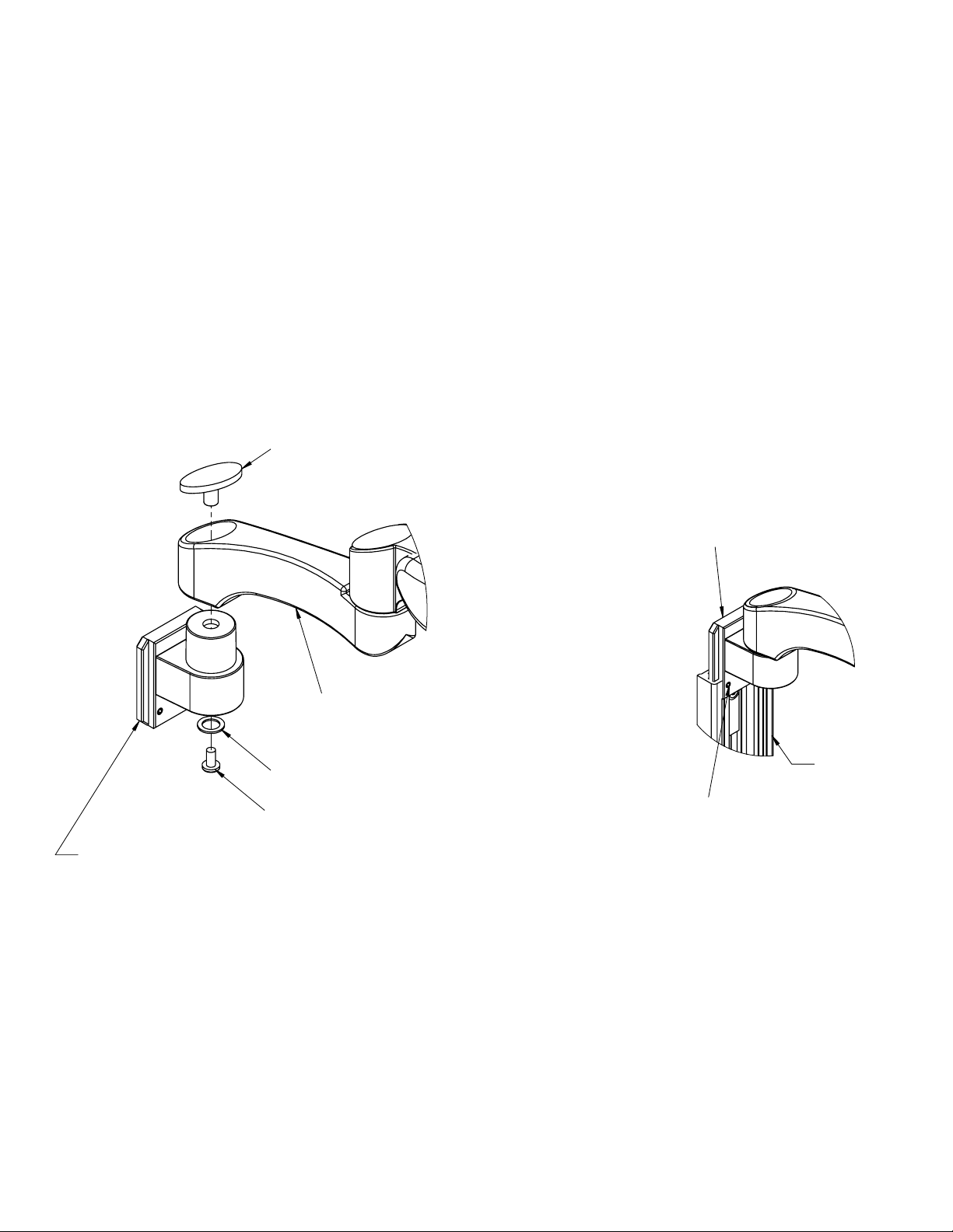
Mounting on the Desk: Clamp Mount Assembly
For Use With: LMA-__-DSK-L-__/LMA-__-DSK-S-__
WARNING It is recommended that the desk clamp be clamped to the side or rear of desktop surface. This
assembly is suitable for square edged desks only. It is the user’s responsibility to make sure the desk structure to
which this clamp is attached can support the combined weight of all components.
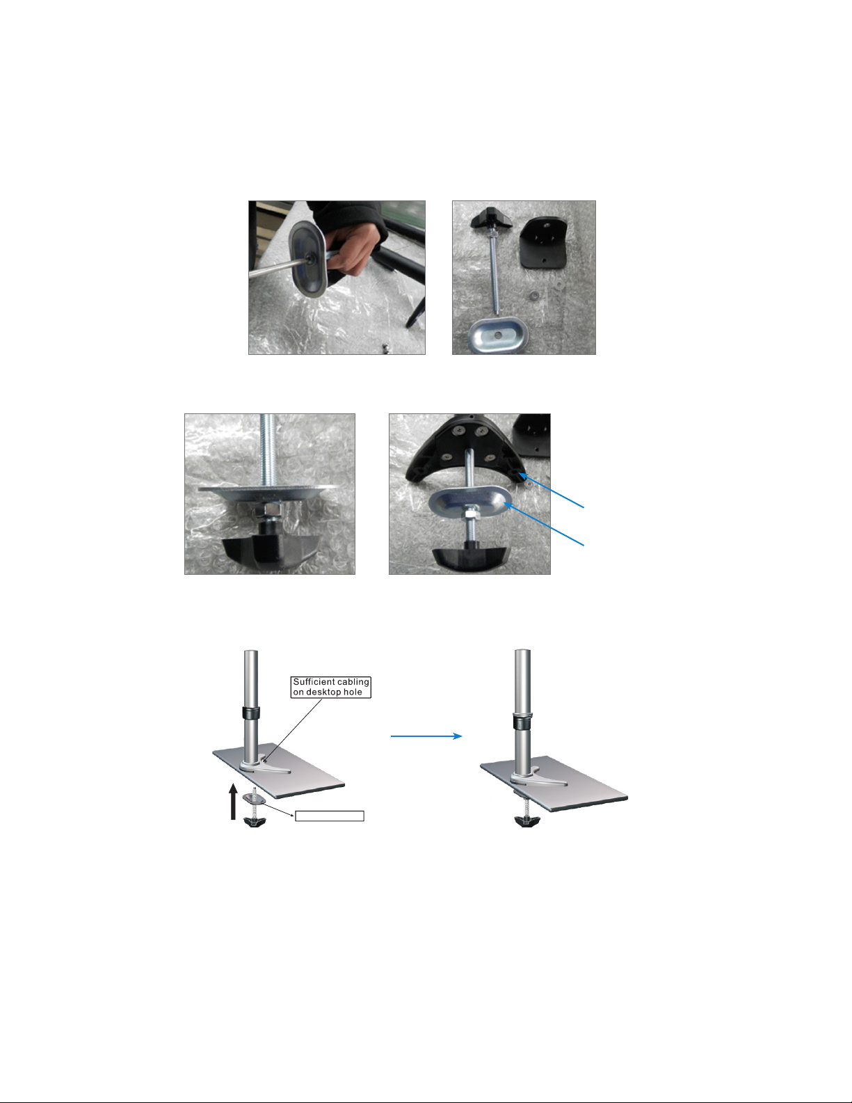
1. Adjust the height of the desk clamp to suit desktop surface.
0.39'' - 2.95''
(9.9 mm - 75 mm)
2. Place the plastic gasket cushion as shown.
3. Place the desk clamp on top of the desk in the desired position and ensure the clamp opening is facing towards
the edge of the desktop. Turn the handle to tighten by hand to ensure that the desk clamp fully contacts the
desktop surface and is secure.
www.amico.com 9
Page 10

SECTION 3: Installation on Mounting Platform
pressure plate
Mounting on the Desk: Clamp Mount Assembly
4. Loosen the collar and adjust the height as desired before installing and tightening the Light Monitor Arm.
Mounting on the Desk: Over Existing Grommet
1. Remove six screws from the existing plate.
2. Secure the grommet plate to the base plate with four screws as shown below.
2.5 mm HEX key
10 Amico Accessories Inc.
Grommet Plate
Base Plate
Page 11
SECTION 3: Installation on Mounting Platform
Mounting on the Desk: Over Existing Grommet
3. Remove the screw from the gripping plate as shown below.
4. Insert the gripping plate into bolt and tighten into base plate as shown below.
Base Plate
Gripping Plate
5. Unscrew the pressure plate and bolt from the base and sandwich desktop surface as shown. Turn and tighten by
hand to ensure that the grommet clamp pressure plate fully contacts the desktop surface and is secure.
pressure plate
6. Refer to “Mounting on the Desk: Clamp Mount Assembly” step 4 on page 10 for collar adjustment and Light
Monitor Arm installation
www.amico.com 11
Page 12
SECTION 4: Device Installation
D
DETAIL D
SCALE 1 : 7
CUSTOMER
MONITOR
(NOT PROVIDED)
4 X M4 screws
(PART OF X-LMA-01/02-01)
LMA-__-(_____)-__
LMA-__-(_____)-__
MONITOR
(NOT PROVIDED)
X-FIT-VSA-PLT
(PART OF LMA-__-(_____)-__
4 X Longer M4 screws
(PART OF X-LMA-01/02-01)
4 X spacers
(PART OF X-LMA-01/02-01)
CUSTOMER
FOR USE WITH: LMA-__-(_____)-__
Determine the monitor configuration. VESA 75 (75 mm x 75 mm M4 thread) or VESA 100 (100 mm x 100 mm M4 threads) and if spacers are required.
1.
VESA 100 configuration: 2 x M4 screws are partially threaded into the top 2 holes at the back of the monitor. The monitor can then be hung up
2.
on the X-FIT-VSA-PLT through the two slots at the top. Insert 2 more screws through the X-FIT-VSA-PLT 100 mounting holes at the bottom
and tighten all screws. (Figure 1)
VESA-75 configuration: Rotate X-FIT-VSA-PLT so the 2 slots for the VESA-75 configuration are located at the top. (Figure 3) Partially thread two screws
3.
into the top 2 holes at the back of the monitor. The monitor can then be hung up on the VESA Head through the two slots at the top. Insert 2
more screws through the VESA-75 mounting holes at the bottom and tighten all screws. (Figure 1)
When removing the monitor, the monitor arm and the monitor should be placed at the highest position. Remove the 2 bottom screws
4.
from the VESA plate, loosen the top 2 screws, and lift the monitor off the VESA plate.
If spacers are required, for both VESA 75 and VESA 100 monitor configurations, place the monitor down on a protective surface. Align and tighten
5.
4x Longer M4 screws through X-FIT-VSA-PLT and spacers into monitor. (Figure 2)
PROJECT 394
Holes for VESA 100 pattern
Holes for VESA 75 pattern
DESCRIPTION:
PART NO:
SCALE:
DRAWN BY:
CHECKED BY:
SHT.
OF
DRAWING NO:
NTS
4
11
PRIVATE AND CONFIDENTIAL
THIS PRINT IS PROPERTY OF AMICO ACCESSORIES
AND IS LOANED IN CONFIDENCE SUBJECT TO RETURN
UPON REQUEST AND WITH THE UNDERSTANDING THAT
NO COPIES ARE TO BE MADE WITHOUT THE CONSENT
OF AMICO ACCESSORIES
ALL RIGHTS TO DESIGN OR INVENTION ARE RESERVED
DATE:
DATE:
JT
2014-05-26
EC
2014-06-10
85 Fulton Way
Richmond Hill, Ontario
L4B 2N4, Canada
Toll Free: 1.877.264.2697 (T)
Tel: (905) 763.7778
Fax: (905) 763.8587
LMA ASSEMBLY
LMA-__-(_____)-__
20140526-E2900
PROJECTION
www.amico.com
CUSTOMER
Holes for VESA 100 pattern
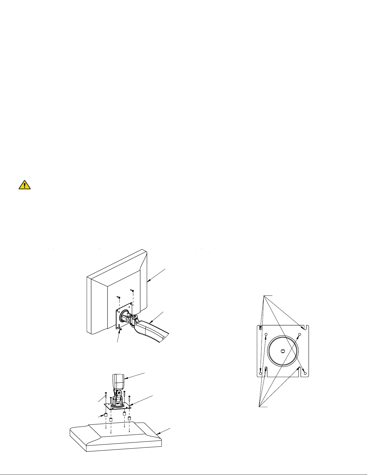
Device Conguration Recommendations
1. Determine the monitor conguration and if spacers are required. The monitor conguration will be either VESA
75 (75 mm x 75 mm M4 thread) or VESA 100 (100 mm x 100 mm M4 threads).
2. For VESA 100 conguration: two M4 screws are partially threaded into the top two holes at the back of the
monitor. The monitor can then be hung up on the X-FIT-VSA-PLT through the two slots at the top. Insert two
more screws through the X-FIT-VSA-PLT 100 mounting holes at the bottom and tighten all screws (Figure 4).
3. For VESA-75 conguration: Rotate X-FIT-VSA-PLT so the two slots for the VESA-75 conguration are located at the
top (Figure 6). Partially thread two screws into the top two holes at the back of the monitor. The monitor can
then be hung up on the VESA head through the two slots at the top. Insert two more screws through the VESA75 mounting holes at the bottom and tighten all screws (Figure 4).
WARNING When removing the monitor, the monitor arm and the monitor should be placed at the highest
position. Remove the two bottom screws from the VESA plate, loosen the top two screws and then lift the
monitor o the VESA plate.
4. If spacers are required, for both VESA 75 and VESA 100 monitor congurations, place the monitor down on a
protective surface. Align and tighten four longer M4 screws through X-FIT-VSA-PLT and spacers into monitor
(Figure 5).
Figure 4
MONITOR
(NOT PROVIDED)
Figure 6
Holes for VESA 100 pattern
4 X M4 screws
(PART OF X-LMA-01/02-01)
LMA-__-(_____)-__
Figure 5
12 Amico Accessories Inc.
Holes for VESA 75 pattern
Page 13
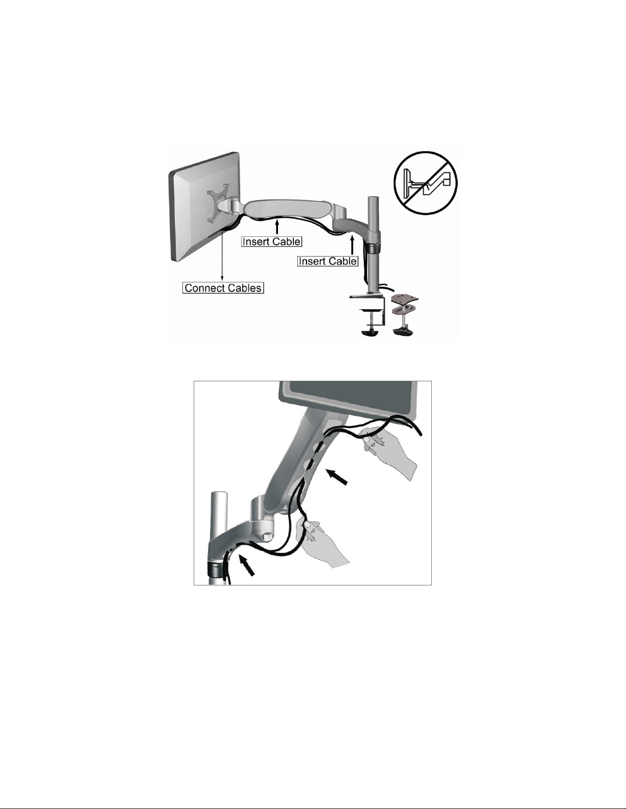
SECTION 4: Device Installation
Cable Management
www.amico.com 13
Page 14

SECTION 5: Adjustments
Adjustment Procedure 1
1. Adjust the screw clockwise for heavier loads and counter-clockwise for lighter loads for counterbalance as
shown in the detailed view below, with a 5 mm HEX key.
2. Tighten or loosen the appropriate screw as shown below to adjust the monitor’s position accordingly. For
swivelling, use a 5 mm HEX key. For tilting, use a 6 mm HEX key.
WARNING Do not loosen top screw. Doing so may cause the head assembly to fall o.
Top screw
Adjustment Procedure 2
1. To adjust the tension on the movement of the arm, tighten or loosen the screw in the appropriate joints as
shown in the detailed view below using a 2.5 mm HEX key.
14 Amico Accessories Inc.
Page 15

SECTION 6: Maintenance and Troubleshooting
Preventive Maintenance
WARNING LMA requires periodic inspection and maintenance to perform optimally and achieve maximum
operation life.
WARNING The intervals shown are recommended. Maintenance schedules should be more frequent for
higher use areas.
Area Maintenance
VESA Adapter
1
2
3
• Check if the adapter plate and the monitor are securely attached. Ensure the four screws on the
mounting plate(s) are fastened to the tightest possible position.
• Visually inspect for any signs of grinding and gapping.
MRS Rail Mount Adapter
• Ensure the two set screws on the channel are fastened to the tightest possible position.
Swivel Joint
• Ensure screw on bottom of joint is fastened to the tightest possible position using a #3 Philips head
screwdriver.
• Ensure set screw at back of joint is tightened. Use a 2.5 mm HEX key to tighten as needed.
Troubleshooting
Symptom Possible cause Solution
Too easy or too dicult to tilt the monitor
up and down
Too easy or too dicult to utilize the
portrait/landscape feature
The entire arm is rocking slightly when in
use
• Excessively loosened or tightened
hardware
• Weight of the monitor is not compatible
with the arm
• Damaged hardware • Please contact Amico Accessories Inc.
Period
(Month)
4
1
1
• Adjust respective screws to control the
correct movement
• Please contact Amico Accessories Inc.
Length of the extension arm is at an angle
Extension arm is not secure or it is rocking
slightly
Arm is too dicult to maneuver with the
monitor
Arm falls to the lowest position on its own
when monitor is attached
Excessive gapping or angling at joints of
arm
• Loosened/damaged hardware
• Damaged extension arm
• Weight of the monitor exceeds the load
rating
• Counterbalance is not adjusted properly
for devices
• Damaged hardware or other physical
damage
• Equipment is too heavy
• Perform preventive maintenance
• Check all screws are secured
• Please contact Amico Accessories Inc.
• Please contact Amico Accessories Inc.
• Adjust for the correct counterbalance
• See section 4: adjustment procedure
• Check device mounted for weight
compatibility. If problem persists
contact Amico Accessories Inc.
If the above solutions do not solve your symptoms or you are in need of parts/hardware, please contact Amico
Accessories, 1.877.264.2697
www.amico.com 15
Page 16

SECTION 6: Maintenance and Troubleshooting
Cleaning
WARNING: The cleaning chemicals and methods below are not meant for controlling any infections. It shall
be the responsibility of the hospital or the hospital’s infection control ocer to sanitize the equipment.
WARNING: Please do not spray any chemical directly onto the arm. Apply onto a soft cloth and wipe clean
to prevent chemicals getting into the internal components of the arm.
The mounting assembly may be cleaned with most mild, non-abrasive solutions commonly used in the hospital
environment (e.g. diluted bleach, ammonia, or alcohol solutions). The surface nish will be permanently damaged by
strong chemicals and solvents such as acetone and trichloroethylene. Steel wool or other abrasive material should never
be used.
Damage caused by the use of unapproved substances or processes will not be warranted. It is recommended that you
test any cleaning solution on a small area of the LMA that is not visible to verify compatibility.
Never submerge the LMA and do not allow liquids to enter it. Wipe any cleaning agents o the LMA immediately using
a water-dampened cloth. Dry the arm thoroughly after cleaning.
Acetone
No Acetone
Acetone is a colorless,
mobile, ammable liquid
No Trichloroethylene
Trichloroethylene is a chlorinated
hydrocarbon commonly used as
an industrial solvent.
Trichloroethylene
16 Amico Accessories Inc.
Page 17

SECTION 7: Product Classication
LMA - - -01
01
With 7" (177.8 mm)
Extension
02
Without Extension
Grommet/Desk Clamp Mount, Short
Grommet/Desk Clamp Mount, Long
DSK-S
6" (152.4 mm)
DSK-L
13" (330 mm)
WAL
Direct Wall Mount
MON
Monitor Channel
VRS
Amico Vertical Direct Mount
www.amico.com 17
Page 18

Accessories
Warranty Policy
Amico Accessories Inc. warrants all mounting accessories to be free from defects in material and workmanship for a period of
twelve (12) months from the date of shipment. Within this period Amico Accessories Inc. will repair or replace any part which is
proven to be defective.
Amico Accessories Inc. will warrant its materials to be free from defect for an additional period of four (4) years, ve (5) years
from the date of shipment. Within this period, Amico Accessories Inc. will replace any part at no charge, which is proven to be
defective. Shipping and Installation costs after the rst twelve (12) months will be borne by the customer.
This warranty is valid only when the product has been properly installed according to Amico Accessories Inc. specications, used
in a normal manner and serviced according to factory recommendations. It does not cover products that are not manufactured
by Amico Accessories Inc. It does not cover failures due to damage which occurs in shipments or failures which resulted from
accidents, misuse, abuse, neglect, mishandling, alteration, misapplication or damage that may be attributable to acts of God.
Amico Accessories Inc. shall not be liable for incidental or consequential damages resulting from use of equipment.
All claims for warranty must rst be approved by Amico Accessories Inc. A valid Return Goods Authorization (RGA) number must
be obtained from Amico Accessories Inc. prior to commencement of any service work. Warranty work, which has not been pre-
authorized by Amico Accessories Inc., will not be reimbursed.
AMICO ACCESSORIES INC. DOES NOT HONOR VERBAL STATEMENTS CONCERNING THE WARRANTY.
The distributor and/or dealer are not sanctioned to create verbal warranties about the product described in this agreement. Any
statements will not be honored or be made part of the agreement of sale. This document is the nal complete and exclusive
terms of the agreement.
THIS WARRANTY IS INCLUSIVE AND REPLACES ALL OTHER WARRANTIES.
Amico Accessories Inc. shall not, under any circumstances be liable for incidental or consequential damages including, but not
limited to, prot, loss of sales or injuries to person(s) or property. Correction of noncompliance as noted above will result in
completion of all liabilities of Amico Accessories Inc., whether based on agreement, neglect or changed materials, designs or
specications without notice.
All claims for warranty must rst be approved by Amico Accessories Inc. Service Department: accessories@amico.com
or 1.877.264.2697). A valid Return Goods Authorization number must be obtained from Amico Accessories Inc. prior to
commencement of any warranty claim.
Page 19

Notes
www.amico.com 19
Page 20

www.amico.com
Amico Accessories Inc. | www.amico.com
85 Fulton Way, Richmond Hill
Ontario, L4B 2N4, Canada
71 East Industry Court, Deer Park
NY 11729, U.S.A.
Toll Free Tel: 1.877.264.2697
Toll Free Fax: 1.866.440.4986
Tel: 905.763.7778
Fax: 905.763.8587
Email: info@amico.com
AAIMLMA 10.16.2014
 Loading...