

Page 1
Approval and Installation Booklet
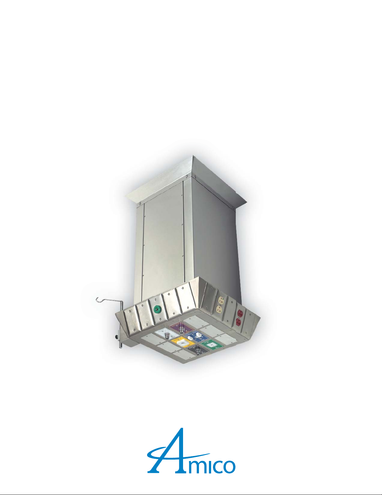
Rigid Stationary Ceiling Column
www.amico.com
Page 2

ABOUT US
Amico Corporation has been a leading manufacturer of Medical Equipment since 1974, selling its products through a global distribution channel from three manufacturing facilities in Canada and the U.S.
With a track record of exceeding expectations, Amico is dedicated to developing and manufacturing the
most advanced medical equipment for the industrial and global Health Care Industry. With over 9 di erent divisions, Amico products o er a total hospital solution.
2 Amico Pipeline
Page 3

Table of Contents
Product Description 3
Cleaning 3
Inspection and Testing 3
Elevation View 4
Device and Accessory Chart 5
Device Placement (Bottom View) 6
Electrical Diagram (Bottom View) 7
Mounting Plate to Outlet Detail 8
Mounting Information 9
Typical Location View 10
Notes 11
2 Amico Pipeline
Page 4

Product Description
The Rigid ceiling column shall be an Amico Alert-1 series.
The shroud is made of 16 gauge stainless steel with a # 4 satin nish consisting of a: removable access panel, stainless steel ceiling collar and a heavy gauge steel mounting plate.
All electrical services are provided by means of EMT metal conduits and gas services are type L, oxygen cleaned copper
pipes. Standard dimensions are 12” X 12” [304.8 mm x 304.8 mm].
NOTE: Nitrogen is type K oxygen cleaned copper pipe.
NOTE: Electrical devices are pre-wired to electrical junction box at the mounting plate, unless other wise stated.
Gases will be manifolded for single point connections to the source. All pipes will extend 8” from the top of mounting plate.
Cleaning
The Amico Outlets are factory cleaned for oxygen service. Exposed surfaces of the outlet may be cleaned with a
mild detergent solution or wiped with a disinfectant commonly used in patient rooms that is compatible with plastics,
anodized aluminium and die cast zinc.
Inspection and Testing
Medical Gas Outlets should be inspected periodically or at least once a year. The test should be in accordance with
NFPA 99 “Gas and Vacuum systems”, or CSA Z7396.1-06 “Non ammable Medical Gas Piping System”.
Test for leaks: Ensure that no leaks exist, with or without the adapter inserted.
Test for Indexing: Only a mating gas speci c adapter should insert smoothly into the outlet, latch and be retained.
Test for Flow:
- Gas Outlets: 120 l/min (4.2 scfm) @ 345 kPa (50 psi), maximum allowable pressure drop is 28 kPa (4 psi).
- Nitrogen Outlet: 400 l/min (14.1 scfm) @ 1,250 kPa (180 psi), maximum allowable pressure drop is 70 kPa (10 psi).
- Vacuum Outlet: 30 l/min (1.1 scfm) @ 54 kPa (16 inHg), maximum allowable pressure drop is 13 kPa (4 inHg).
Refer to the appropriate standards for the proper way of performing the ow test.
NOTE: The Amico medical gas and vacuum outlets meet and exceed these requirements at the time of manufacture. However piping source capacity, sizing and restrictions may prevent outlets from attaining these values.
www.amico.com 3
Page 5

Elevation View
To accommodate di erent ceiling heights, Amico Corporation has standardized three di erent variations.
Please select the required nominal column height below:
L1= Nominal Column Height
30” (762mm)
36” (914.4mm)
42” (1066.8mm)
Ceiling Height:
Column Height
Floor Clearance:
Ceiling Height
L1
Ceiling
Height
Floor Clearance
78" [1981.2mm]*
Quantity
Finished Floor Line
* Recommended Floor Clearance
NOTE: Custom heights are available at an additional cost. Please contact Amico for pricing.
Approval Signature Date Phone No.
4 Amico Pipeline
Page 6
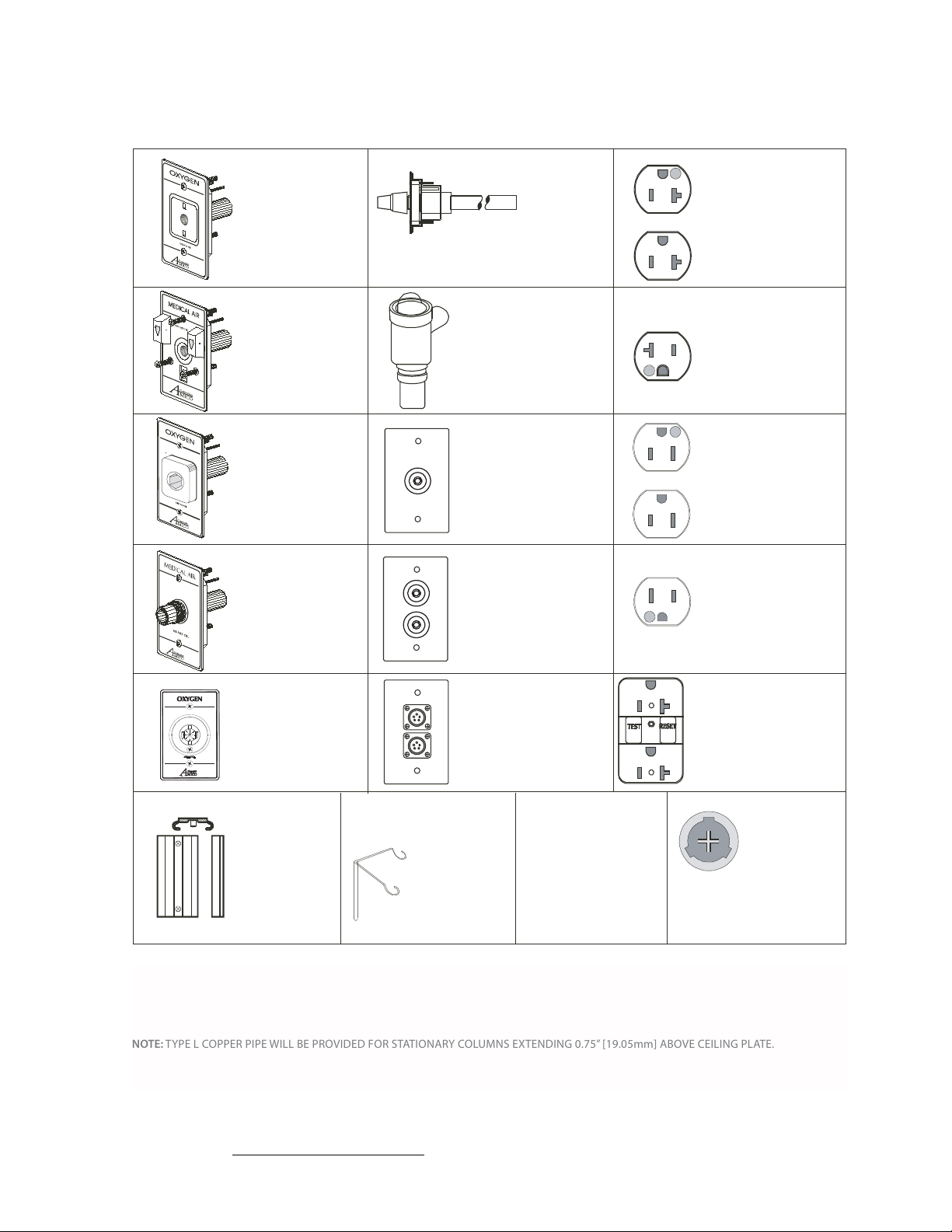
Device and Accessory Chart
*QD
XXX
Ohmeda / Medaes
Compatible
CH
XXX
Chemetron
Compatible
PB
XXX
Puritan-Bennett
Compatible
*DI
XXX
DISS
PE
Ceiling Column
Passive Evacuation
(19mm/33mm)
IMP
Passive Evacuation
with Impedance
V al ve (19mm /2 2mm)
(Side Mount Only)
GJ
Ground Jack
Receptacle
Single Hampden
(SLR-3)
GREEN
GJ2
Ground Jack
Receptacle
Dual Hampden
(SLR-3)
GREEN
E9-RED
E10-IVO.
Duplex Receptacle
8300-HG
125V/20a
(US / International)
E11-RED
E12-IVO.
Single Receptacle
8310-HG
125V/20a
(US / International)
E5-RED
E6-IVO.
Duplex Receptacle
8200-HG
125V/15a
(CAN / International)
E7-RED
E8-IVO.
Single Receptacle
8210-HG
125V/15a
(CAN / Internatio
nal)
E13-RED
E14-IVO.
Oxequip
Compatible
SL
OX
XXX
Monitor Jack
Duplex
(5-pin shown)
Amphenol Model
10-825806-05S
97-14S-5S
IV
MJ
E13C-RED
E14C-IVO.
Ground Fault Circuit
Interrupter
(C = Canadian)
DJ
DP
Data - Telephone
Vacuum
Bottle Slide
ALL ELECTRICAL DEVICES ARE HUBBELL BRAND
NOTE: CARBON DIOXIDE OUTLETS ARE NOT AVAILABLE IN PURITAIN-BENNETT. NITROGEN OUTLETS ARE ONLY AVAILABLE IN DISS.
NOTE: TYPE L COPPER PIPE WILL BE PROVIDED FOR STATIONARY COLUMNS EXTENDING 0.75” [19.05mm] ABOVE CEILING PLATE.
Stai nless Steel
IV Hook
(Duplex only)
Communication Jack or
Duplex Receptacle
(Provision Only)
DP - Duplex Receptacle
Provision
Twist-Lock
Receptacle
Hubble 23000-HG
125V/20a
TL
Approval Signature Date Phone No.
www.amico.com 5
Page 7

Device Placement (Bottom View)
Please fill the devices that you require for your application.
(Specify by using the symbols on Page 5 of this Approval Booklet.)
Nitrogen Control Panel
Yes
No
Location of Nitrogen Control Panel
Side A
Side B
Side C
Side D
Please Specify Outlet Language
US
CAN
FRENCH
SPANISH/US
SPANISH/ISO
Gas Legend
Oxygen = O
Medical Air = A
Vacuum = V
Nitrous Oxide = 2
Nitrogen = N
Carbon Dioxide = C
Positions 1 - 12 = Medical Gas Outlets
Posititions A1 - D5 = Electrical and/or communication devices
NOTE:
1. Two electrical/communication/medical gas devices cannot be placed together at any corner.
WAGD (US) = W
AGSS (Canada) = E
Instrument Air = I
2. Maximum of 2 D5 provisions only.
3. The Nitrogen Control Panel will occupy three spaces of the bulkhead (E.G. A2 to A4).
Approval Signature Date Phone No.
6 Amico Pipeline
Page 8

Electrical Diagram (Bottom View)
____ gauge
____ gauge
_______________________
_______________________
10 gauge
Green
*Please Select One of the Following:
Amico r
ecommended circuit schedule based on layout
Custom circuit schedule. Please specify on circuit chart
Receptacle Type:
US/CAN
*BRITISH (simplex only)
*GERMAN (simplex only)
*Please specify electrical details:
Type of wire:
THHN XHHW RW90
NOTE:
1. Two electrical/communication/medical gas devices
cannot be placed together at any corner.
Circuit Chart
AWG Wire Gauge: Wire Color:
10 & 12 LIVE/HOT
10 & 12 NEUTRAL
10 GROUND
Isolated Power
Please select one of the following
All receptacles shall be mounted with
ground pin “DOWN”
All receptacles shall be mounted with
ground pin “UP” (Default)
2. If type of wire & gauge is not specified, Amico
will use the following:
For US/International
LIVE/HOT - 12 Ga. THHN Wire Black
NEUTRAL - 12 Ga. THHN Wire White
GROUND - 10 Ga. THHN Wire Green
For Canada
LIVE/HOT - 12 Ga. RW90 Wire Black
NEUTRAL - 12 Ga. RW90 Wire White
GROUND - 10 Ga. RW90 Wire Green
3. Conduit: 1/2” [12.7mm] rigid EMT.
3/4" rigid EMT for low voltage provision.
4. All conduits and wires will extend a minimum of12”
[304.8mm] above nish column for connection
to riser plate.
5. A pull-string will be provided to be connected by
others for all ground jacks and data provision.
6. British or German Receptacle cannot be positioned
side by side ie: A1 and A2.
Approval Signature Date Phone No.
www.amico.com 7
Page 9
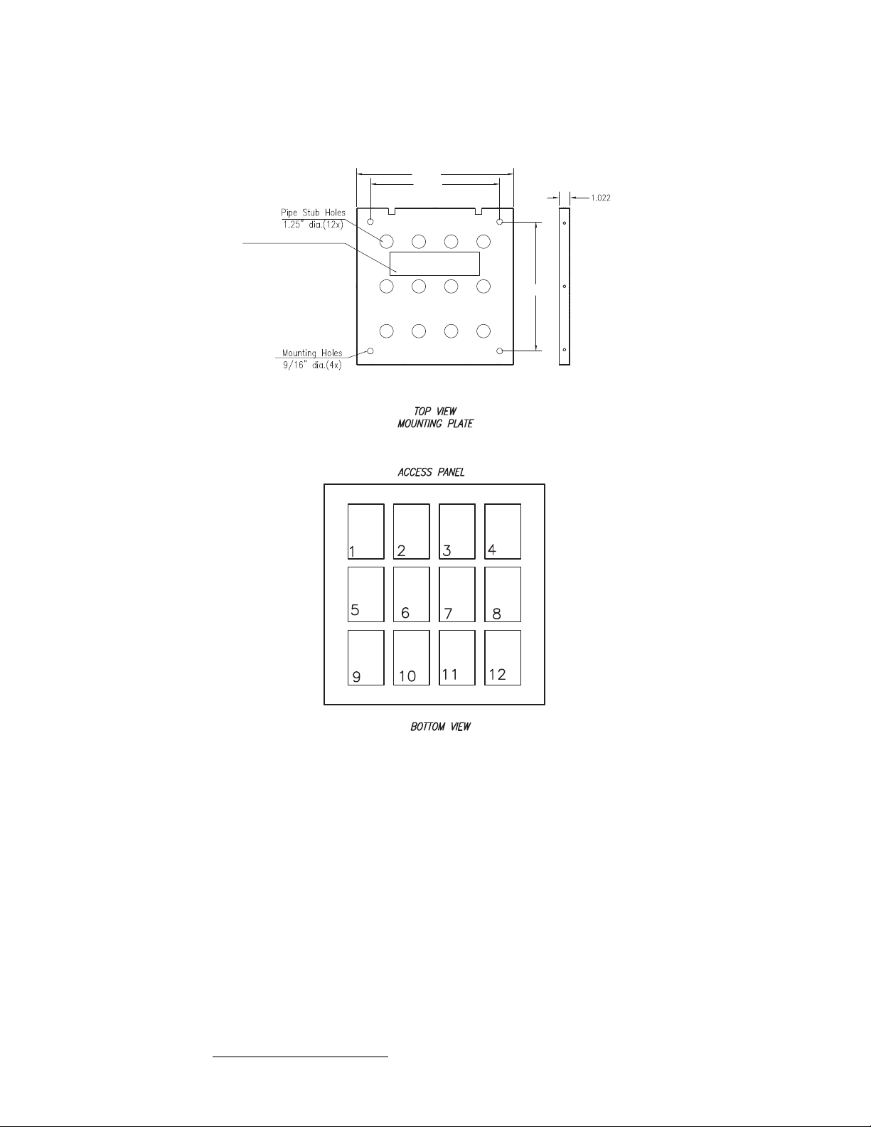
Mounting Plate to Outlet Detail
11.880”
10.00”
Access Panel
Electrical Termination Box
2.0” x 9.0”
10”
NOTE:
1. Gases will be manifolded for single point connections from source.
2. All pipes will extend 8” from the top of mounting plate.
3. Pipe stubs diameters are:
- 3/4” dia. for vacuum, WAGD, and AGSS (Type L)
-1/2” dia. for medical air, oxygen, and nitrous oxide (Type L)
-1/2” dia. for nitrogen (Type K)
4. Exact locations of gas terminations on mounting plate will be determined after receiving the booklet.
Approval Signature Date Phone No.
8 Amico Pipeline
Page 10

Mounting Information
STRUCTURAL
CEILING
FINISHED CEILING
10"
[254mm]
6" [152.4mm]
RECOMMENDED
12" [304.8mm] SQUARE
MOUNTING PLATE
15-5/8" [396.88mm] SQUARE
CEILING COVER FIELD
MOUNTED
1/2" 12.7mm THREADED
ROD TYP. OF 4 BY OTHERS
ANTI-SWAY
SUPPORT STRUCTURE
(SUPPLIED BY OTHERS)
NOTE:
1. All labour and material for installation of mounting plate to mounting structure supplied by others.
2. Installer has nal responsibility for the strength and stability of the mounting structure that is supplied by others.
3. Mounting plate is xed to the column and cannot be pre-shipped.
4. Mounting plate to be mounted ush with nished ceiling.
5. Mounting structure supplied by others.
6. Gas pipes extend 8” above the column.
Approval Signature Date Phone No.
www.amico.com 9
Page 11

Typical Location View
3’ - 4’
[914.4 - 1219.2mm]
3’ - 4’
[914.4 - 1219.2mm]
3’ - 4’
[914.4 - 1219.2mm]
3’ - 4’
[914.4 - 1219.2mm]
10 Amico Pipeline
Approval Signature Date Phone No.
Page 12

www.amico.com
Amico Architectural | www.amico.com
85 Fulton Way, Richmond Hill
Ontario, L
4B 2N4, Canada
71 East Industry Court, Deer Park
NY 11729, U.S.A
Toll Free Tel: 1.877.264.2697
Toll Free Fax: 1.866.440.4986
Tel: 905.763.7778
Fax: 905.763.8587
Email: info@amico.com
C US LISTED
ac_instal_maint_rigid_retr_stnry_col PRINTED FEB 12
 Loading...