

Page 1

Operating & Maintenance Manual
www.amico.com
Alert-3 LCD Alarm v2.0
1ST FLOOR
ROO M 12
4TH FLOOR
ROOM 47
2ND FLOOR
ROOM 25
5TH FLOOR
ROOM 58
3RD FLOOR ROOM 37
MAINTEN EX T 302
Page 2

Contents
User Responsibility 3
Introduction 3 - 4
Features
Description of the Alarm 5 - 6
Shipment Details 5
The Alarm Back Box 5
The Frame/Module Assembly 5
System Power Supply 6
LCD Module 6
Sensor Module 6
Installation Guide 7 - 11
The Alarm Back Box 6
For Local Sensor Only 6
Standing Pressure Test 6
Sensor 6 - 7
Local 6
Remote 7
Frame/Module Assembly 7
System Power Supply 8
Sensor Module 9 - 10
Gas Display 9
Local 9
Remote 9
LCD Display Module 9
LCD Display Setup 10
Closing The Frame/Module Assembly 10 - 11
Programming Gas Locations 12
Model Numbers 13
Spare Part Numbers 14 - 15
Sensors 14
Alert-3 Alarm Accessories 14
Demand Check Valves 15
Dimensions 16
2 Amico Pipeline
Page 3

Contents
Troubleshooting 17 - 19
Appendix A 20
Wiring Diagram: LCD Motherboard
Appendix B 21
Wiring Diagram: Auto-Switch Power Supply
Appendix C 22
Wiring Diagram: LCD Display Module - Alarm Buzzer
Appendix D 23
Wiring Diagram: LCD Display Module - Local Sensor
Appendix E 24
Wiring Diagram: LCD Display Module - Remote Sensor
Appendix F 25
Wiring Diagram: LCD Display Module - Master Module
Appendix G 26
Technical Specications
www.amico.com 3
Page 4
User Responsibility
Amico Microprocessor Based Alarm
USER RESPONSIBILITY
The information contained in this Installation and Operation Maintenance
Manual, pertains only to the ALERT-2 microprocessor based digital alarm.
This product will perform to conformity with the descriptions contained in this
manual, when assembled, operated, maintained and serviced in accordance
with the installation instructions provided.
The alarm must be checked periodically. Parts that are broken, missing,
worn, distorted or contaminated, must be replaced immediately. Should such
repair or replacement become necessary, please contact Amico Corporation
or their distributors.
All alarms should not be repaired, or altered without prior written or verbal
approval of Amico Corporation or it’s distributors. Failure to comply will void
all warranty on the alarm.
Statements in this manual preceded by the words
WARNING, CAUTION,
DANGER and
NOTE are of special significance. Please read these sections
carefully.
WARNING: denotes steps which can prevent injury.
CAUTION: denotes steps which can prevent damage to equipment.
DANGER: denotes steps which can prevent electrical shock to equipment
or to prevent serious injury and/or death.
The information contained in this Installation, Operation and Maintenance Manual pertains only to the Alert-3
microprocessor based digital LCD Alarm. This product will perform as described in this manual when assembled,
operated, maintained and serviced in accordance with the installation instructions provided.
The alarm must be checked periodically. Parts that are broken, missing, worn, distorted or contaminated must be
replaced immediately. Should such repair or replacement become necessary, please contact Amico Corporation or their
distributors.
All alarms should not be repaired or altered without prior written or verbal approval from Amico Corporation or its
distributors. Failure to comply will void all warranty on the alarm.
Statements in this manual preceded by the words WARNING, CAUTION, DANGER and NOTE are of special signicance.
Please read these sections carefully.
WARNING: denotes steps which can prevent injury.
CAUTION: denotes steps which can prevent damage to equipment.
Introduction
The Amico Medical Gas LCD Alarm System (Alert-3) incorporates the latest microprocessor based technology for alarm
and surveillance systems. The alarm has been designed to provide user exibility and reliability. This manual shall enable
the customer to install, use and maintain the alarm appropriately.
There is one “MUTE” ( ) or “PUSH TO TEST” button located on the front face of the LCD panel. The button has two
functions: to silence an alarm that has occurred and to view the audible alarm sound level and high and low set points.
When an audible alarm is triggered, press the button to silence the alarm. To view the audible alarm sound level and high
and low set points, press and hold the button for 20 seconds to display the information on the LCD Alarm screen.
DANGER: denotes steps which can prevent electrical shock to equipment
or to prevent serious injury and/or death.
All Gases or Vacuums are displayed on the LCD screen for clear visibility, to facilitate the monitoring function by hospital
personnel. Under normal operation, the gas indicator will be in the “GREEN - OK” position. If an alarm condition occurs, a
“RED-Alarm” indicator will be displayed and an audible alarm shall be continuous until silenced by pushing the “MUTE”
button.
The LCD Alarm can be connected to a “Building Management System” for a generic alarm indicator.
4 Amico Pipeline
Page 5

Features
• Microprocessor based digital LCD and individual microprocessor on each sensor module
• Gas-specic sensors can be mounted locally or remotely, up to 100 feet [30.5 m], utilizing 22 gauge shielded
twisted pair (2 shielded wires)
• DISS gas-specic sensor housed in a tamper-proof enclosure. The Sensor Module is housed in an anodized
aluminum and nickel-plated brass enclosure to act as an interference barrier
• The Sensor Module is the smallest computer-calibrated temperature-compensated sensor in the industry
• PSI, kPa, inHg or BAR display (programmable)
• Self diagnostic circuitry with error display for problem identication
• Highly accurate Solid State Pressure piezo-resistive transducer
• Dry contacts for remote monitoring from LCD for a generic alarm condition
• Modules are factory mounted on a hinged frame assembly for ease of installation and maintenance
• Field programmable push buttons for adjustment of “HI” and “LOW” set-points on display module
• LCD Alarm available in 1 to 8 gases
Description of the Alarm
SHIPMENT DETAILS
When you receive an Alert-3 LCD series alarm from Amico Corporation, the package will consist of three main sections:
the Alarm Back Box, Sensors and the Frame/Module Assembly.
THE ALARM BACK BOX
The Alarm Back Box contains the auto-switchable System Power Supply with an ON/OFF switch, a built-in fuse and
terminal blocks (115 to 220 VAC - 50 to 60 Hz). The back box also incorporates the pipe stubs for applications that require
locally (in box) mounted sensors.
THE FRAME/MODULE ASSEMBLY
The Frame/Module Assembly consists of the frame and the LCD module. The hinged frame is designed to swing down
from the back box to facilitate installation and servicing of the alarm. This design will reduce installation time and
eliminate the risk of improper installation since all the modules are connected and tested at the factory.
www.amico.com 5
Page 6

Description of Modules
The Alert-3 LCD Alarm is a high technology microprocessor based module:
COMMON TO ALL ALARMS
SYSTEM POWER SUPPLY
The System Power Supply has been pre-installed into the back box assembly. The System Power Supply converts the
AC voltage supply to the alarm into two voltages: 5 VDC (regulated) required by the microprocessor hardware and 15
VDC (unregulated) required by the buzzer and the LCD. This unit also contains the main ON/OFF power switch, the
transformer, the heat sink, the main fuse and fuse cover, the rectifying circuitry, the terminal blocks and the low voltage
DC power cable for connecting this unit to the module. The System Power Supply can be easily removed and reinstalled
by unscrewing it from the back box.
LCD MODULE
The LCD Module contains the LCD screen, microprocessor, buzzer and the “MUTE” buttons. The function of the “MUTE”
button is to silence an alarm that has occurred. By holding the “MUTE” button for 15 seconds, the module will display
the high and low pressure set points. This module also contains a fail-safe relay that de-energizes when the buzzer
is activated. This relay can be used with the Amico Remote Buzzer for applications requiring a remote audible alarm or a
Building Management System.
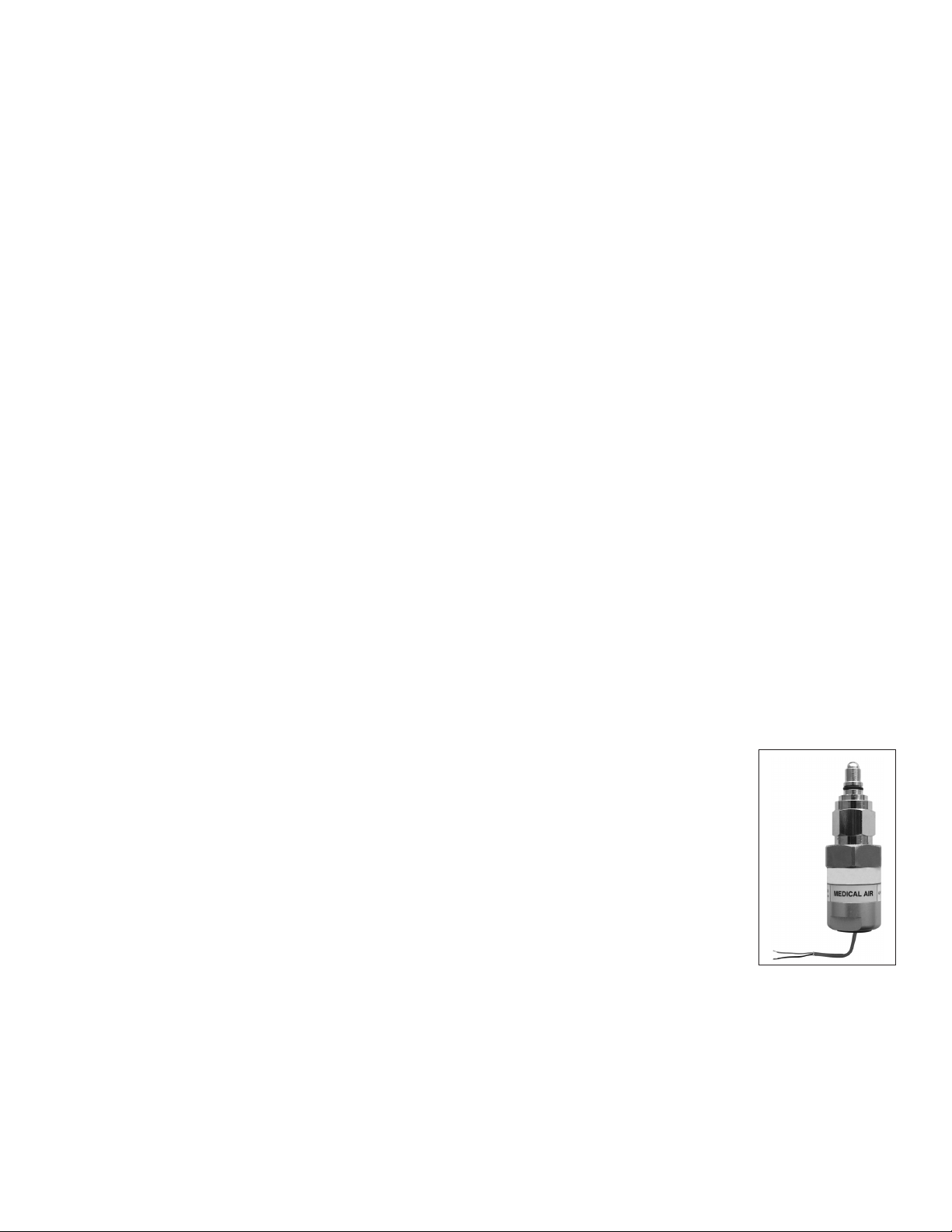
SENSOR MODULE
The Sensor Module contains the transducer which converts the source of the pressure/vacuum into a digital signal that
is displayed on the LCD module. The sensor module shall be housed in an anodized aluminum and nickel-plated brass
enclosure to act as an interference barrier and it is temperature compensated. Each sensor is clearly labeled and color
coded for the gas or vacuum being monitored. The sensor module contains a gas-specic DISS tting to ensure correct
connection of the proper sensor to the respective gas. Each sensor has been factory calibrated by computer for the
specic gas shown on the sensor housing.
6 Amico Pipeline
Page 7
Installation Guide
STEP 1: THE ALARM BOX
Install the back-box to the studs of the wall at the desired height. Ensure that the box is securely in place. The mounting
brackets are adjustable to suit the thickness of the wall. MAKE SURE the box is parallel, squared and ush with the
nished wall surface to ensure that the frame assembly will t properly.
STEP 2: FOR LOCAL SENSOR ONLY
If the sensors are to be mounted locally (inside the back box), the pipe stubs must be connected to the pipeline. Using
silver-brazing techniques, connect each pipe stub to its appropriate gas or vacuum while ensuring that the bottom of
the pipe stub is wrapped with a damp cloth. BE CAREFUL not to damage the DISS check-valve by overheating the lower
portion of the copper pipe. When the brazing of pipe stubs has been completed, the system can be pressure tested.
STEP 3: STANDING PRESSURE TEST
Perform a standing pressure test on the piping system as per NFPA-99 “Health Care Facilities.” Inspect all joints for leaks
and make certain each gas is piped to a correspondingly labeled gas service.
STEP 4: SENSOR
LOCAL (inside the back box)
i. Locate the gas-specic sensor module to be installed.
ii. In the back box, there are color coded gas labels located under the DISS Demand Check Valves. Each label
identies where each sensor module is to be placed.
iii. The sensor module contains a gas-specic DISS tting. Push the sensor module hex-nut
and nipple adapter up into the demand check-valve. With a wrench, tighten the nut so
that it makes a good seal.
Note: Pressure on sensors are not to exceed 250 psi for pressure sensors and 30 inHg for vacuum
sensors.
Alert-3 sensor operating pressure range:
Mid Pressure (0 to 99 psi) - Oxygen, Medical Air, Nitrous Oxide, Carbon Dioxide
High Pressure (0 to 249 psi) - Nitrogen, Instrument Air
Vacuum (0 to 30 inHg) - Vacuum, WAGD, AGSS
www.amico.com 7
Page 8

250psi
WARNING, CAUTION,
NOTE are of special significance. Please read these sections
WARNING: denotes steps which can prevent injury.
Installation Guide
B: REMOTE (outside the back box)
i. Connect a tee (supplied by others) to the pipeline with a 1/4” NPT female
connection that will accept the DISS Demand Check Valve.
ii. Locate the gas-specic sensor module to be installed.
iii. Thread the DISS Demand Check Valve into the correct gas pipeline.
iv. The sensor module contains a gas-specic DISS tting. Push the sensor
module hex-nut and nipple adapter into the demand check-valve. With a
wrench, tighten the nut so that it makes a good seal.
STEP 5: FRAME/MODULE ASSEMBLY
i. Remove the frame/module assembly from its protective box.
ii. Remove the corner screws from the front frame section (4 screws).
iii. Attach the LCD module to the back box assembly by using at head screws
(provided with frame in a plastic bag) to the hinge located on the back box.
iv. Attach the frame wire with 2 dome head screws (provided with frame in a
plastic bag). This will allow the frame assembly and back box to be fastened
securely together.
CAUTION: The microprocessor circuitry on the ALERT-3 alarm contains sophisticated integrated
semiconductors. If it becomes necessary to remove LCD circuit board, PLEASE hold the boards by the
edges. DO NOT TOUCH any of the components on the board. Static discharge can cause the modules
to malfunction or become damaged.
8 Amico Pipeline
Page 9

WARNING, CAUTION,
NOTE are of special significance. Please read these sections
WARNING: denotes steps which can prevent injury.
Installation Guide
STEP 6: SYSTEM POWER SUPPLY
TURN OFF POWER SWITCH before changing any modules and/or disconnecting any cables. Failure to do
so can cause the fuse to blow, damaging the circuitry.
i. Ensure that the ON/OFF switch is in the OFF position.
ii. Through the top left side of the back box, bring in the AC power wires. Knockouts are provided for making
conduit connections to the box. All wiring is to be installed according to local and national codes.
iii. Connect the AC power to the terminal blocks as shown in the wiring diagram (see Appendix B).
STEP 7: SENSOR MODULE
A: Gas Display (on screen location)
The location of gases displayed on screen is dependant upon which sensor channel each individual gas is connected
to. The display below indicates which sensor channel corresponds to each location the gas will be displayed on the LCD
screen.
1 1
1 2 3
2
1 2 3
1
3
2
1 2 3 4
2
3
1
1 2 3 4
4
4 5
4 5 6
5 6 7
5 6 7 8
www.amico.com 9
Page 10

Installation Guide
STEP 7: SENSOR MODULE
B: LOCAL (inside the back box)
i. The sensor module is provided with a 6”-8” [0.1 m - 0.2 m] twisted pair of wires.
One wire is red (positive) and the other wire is black (negative). Connect the wires
to the display module as shown in Appendix D. Take the red wire from the sensor
and attach it to terminal “Sensor +” on the display module. Take the black wire
from the sensor and attach it to terminal “Sensor -”. The terminal block on the
display module is clearly marked for proper connection of the sensor wires.
ii. Repeat the above procedures with the remaining sensor modules.
C: REMOTE (outside the back box)
i. The sensor module is provided with a 6” - 8” [0.1m - 0.2m] twisted pair of wires.
Connect the wires to a junction box (not supplied) located near the sensor as per
the wiring diagram.
ii. Connect a shielded twisted pair cable from the junction box to the back box
assembly. Knockouts are provided throughout the alarm back box. Up to 100 feet
[30.5 m] of 22 Gauge, shielded twisted pair cable should be used.
iii. Connect the red wire from the cable to the terminal on the display module
marked ”Sensor +”. Connect the black wire to terminal “Sensor -” as shown in the
wiring diagram (see Appendix E).
iv. Repeat the above procedures with the remaining sensor modules using the wiring
diagram.
NOTE: When remote sensors are used, a shielded or twisted pair cable is required
(BELDEN #8451 or equivalent, supplied by others).
STEP 8: LCD DISPLAY MODULE
If the dry contacts for a generic alarm is to be used for remote monitoring, connect the wires
to the appropriate terminals: COM (Common), NO (Normally Open) or NC (Normally Closed),
using the diagram in Appendix A.
See Appendix G for contact rating.
Once the sensors are connected and the power has been turned on, use the following steps
to setup the LCD Alarm.
10 Amico Pipeline
Page 11

Installation Guide
STEP 9: LCD DISPLAY SETUP
i. Press the SETUP button (B1) and press the SELECT button (B4)
ii. Volume control: 90, 80, 70, 60 – press CHANGE UP/DOWN to change noise level
iii. Press SELECT for LCD brightness and press CHANGE UP/DOWN to change LCD
brightness
iv. Press the SELECT button (B4)
* The following should be displayed.
SENSOR: 1
SENSOR TYPE: show the gas (example: NITROUS OXIDE)
UNITS: PSI (to change to kPA, Bar, inHg, mmHg: press button CHANGE DOWN/UP then
press SELECT)
LOW ALARM: 40 (to change: press button CHANGE DOWN/UP then press SELECT)
HIGH ALARM: 60 (to change: press button CHANGE DOWN/UP then press SELECT)
CURRENT PRESSURE: displays exact pressure for the line
CURRENT OFF SET: to re-calibrate pressure reading press button CHANGE DOWN/UP
then press SELECT
v. Repeat steps until all sensors are scanned and data is saved. Next it will show
SETUP COMPLETE.
*All gases should now be displayed. If any errors occur, repeat the steps above.
NOTE: Hold the “MUTE” button for twenty (20) seconds to display current low and high set
points.
NOTE: Press the Setup button (B1) in order to make corrections/go back.
STEP 10: CLOSING THE FRAME/MODULE ASSEMBLY
i. Close the frame panel by tightening the screws found on the frame panel to the
back box. Ensure that the screws are securely fastened to keep the LCD Alarm
closed.
ii. Carefully place the front frame over the frame panel. Screw in the screws that
were removed in Step 5, part ii. The alarm shall now be ready for use.
www.amico.com 11
Page 12

Programming Gas Locations
1. Use the Notepad program to enter information for gas location. Each line can hold up to a maximum of 16
characters.
2. Two lines may be used per individual gas.
3. The order of the text must go in order of gas; meaning the rst two lines of text shall represent the 1st gas
location, the next two lines of text shall represent the 2nd gas location, and so forth.
• Please refer to the diagram in the Installation Guide under section 7a to determine gas location on the LCD Alarm
screen.
4. Once all the text has been inputted, save the le on to the SD Card with the le name; location.
5. Insert the SD Card into the SD Card Slot on the LCD Alarm board (Refer to Appendix A).
6. While the LCD Alarm is on; press the reset button, then press and hold the setup button until the information from
the le saved on the SD Card (location.txt) appears on the LCD Alarm Screen.
• If the gas location text does not appear on the screen, repeat step #6. If the problem persists, contact Amico
Corporation for further assistance.
7. Once the text is visible on the LCD Alarm screen, leave the SD Card in the slot for approximately 1 minute in order
for the information to be completely uploaded onto the alarm, and then proceed to remove the card.
8. Once the card has been removed, restart the LCD Alarm to ensure that the locations have been saved onto the
LCD Alarm.
• NOTE: Only capital letters and spaces will be displayed on screen. Small caps, symbols and special characters
cannot be displayed.
• Programming of the gas location is only available for V864 and up. If gas location is required, a new front frame
assembly is required; part number A3P-FRMASS-LCD.
1ST FLOOR
ROOM 12
4TH FLOOR
ROOM 47
2ND FLOOR
ROOM 25
5TH FLOOR
ROOM 58
3RD FLOOR ROOM 37
MAINTEN EXT 302
6TH FLOOR ROOM 65
ENGINEER EXT 302
Notepad File Updated Display on LCD Alarm
12 Amico Pipeline
Page 13

Model Numbers
LCD ALARM
A3AR-L-XXXXXXXX
R = Remote/Local
C = Conversion (Retrot)
ALERT-3 SENSOR MODULE
“L” Denes the Language:
U = English (NFPA)
E = English (CSA/ISO)
F = French (CSA/ISO)
S = Spanish (NFPA/ISO)
A3P-SENS-L-GAS
”X” Denes the Type of Gas:
Oxygen = O
Medical Air = A
MedVac = V
Nitrous Oxide = 2
Nitrogen = N
Carbon Dioxide = C
Waste Anesthetic = W
Gas Disposal (NFPA)
Anesthetic = E
Gas Scavenging
System (CSA/ISO)
Instrument Air = I
“L” Denes the Language:
U = English (NFPA)
E = English (CSA/ISO)
F = French (CSA/ISO)
S = Spanish (NFPA/ISO)
NOTE:
Each Alert-3 Sensor comes with an A2P-PIPE
“Gas” Denes the Type of Gas:
Oxygen = OXY
Medical Air = AIR
MedVac = VAC
Nitrous Oxide = N2O
Nitrogen = NIT
Carbon Dioxide = CO2
Waste Anesthetic = WAG
Gas Disposal
Anesthetic = AGS
Gas Scavenging
System
Instrument Air = IAR
www.amico.com 13
Page 14

Spare Part Numbers
SENSORS
Model Number Description
A3P-SENS-E-AIR
Sensor Module ISO-AIR Eng. Alert-3
A3P-SENS-E-CO2
A3P-SENS-E-AGS
A3P-SENS-E-N2O
A3P-SENS-E-NIT
A3P-SENS-E-OXY
A3P-SENS-E-VAC
A3P-SENS-E-IAR
A3P-SENS-U-AIR
A3P-SENS-U-OXY
A3P-SENS-U-VAC
A3P-SENS-U-WAG
A3P-SENS-U-IAR
Sensor Module ISO-CO2 Eng. Alert-3
Sensor Module ISO-AGS Eng. Alert-3
Sensor Module ISO-N2O Eng. Alert-3
Sensor Module ISO-NIT Eng. Alert-3
Sensor Module ISO-OXY Eng. Alert-3
Sensor Module ISO-VAC Eng. Alert-3
Sensor Module ISO-IAR Eng. Alert-3
Sensor Module USA-AIR Eng. Alert-3
Sensor Module USA-OXY Eng. Alert-3
Sensor Module USA-VAC Eng. Alert-3
Sensor Module USA-WAG Eng. Alert-3
Sensor Module USA-IAR Eng. Alert-3
ACCESSORIES/MISC.
Model Number Description
A3-MAN-ALM-ENG Alert-3 Alarm Manual English
A2P-POWER-V2 Power Supply Module Alert-2
A2P-BOXASS-3LCD Alarm Back Box Assembly 3-Station Alert-2
A3P-FRMASS-LCD LCD Alarm Frame Assembly for LCD Alert-3
A2P-PIPE Pressure Module Pipe Assembly (Alert-2)
A3P-DEMO-CASE Alert-3 Demo Alarm
A2X-BOX-3-FILL Alert-2 Alarm Box Filler Frame 3-Station
A3X-P-SW-PVCAP LCD PVA Switch Cap-Gray
A3X-LCD-LABEL LCD Alarm Front Label
A3X-LCD-LABEL-MUTE Alert-3 Mute Label
14 Amico Pipeline
Page 15

Spare Part Numbers
DEMAND CHECK VALVES
Model Number Description
S-DIS-DEMC-AIR DISS Demand Check Valve 1/4” MNPT - AIR
S-DIS-DEMC-CO2 DISS Demand Check Valve 1/4” MNPT - CO2
S-DIS-DEMC-NIT DISS Demand Check Valve 1/4” MNPT - NIT
S-DIS-DEMC-N2O DISS Demand Check Valve 1/4” MNPT - N2O
S-DIS-DEMC-EVA DISS Demand Check Valve 1/4” MNPT - EVA
S-DIS-DEMC-OXY DISS Demand Check Valve 1/4” MNPT - OXY
S-DIS-DEMC-VAC DISS Demand Check Valve 1/4” MNPT - VAC
S-DIS-KIT-OXY DISS Demand Check, Nut and Nipple - OXY
S-DIS-KIT-AIR DISS Demand Check, Nut and Nipple- AIR
S-DIS-KIT-VAC DISS Demand Check, Nut and Nipple- VAC
S-DIS-KIT-N2O DISS Demand Check, Nut and Nipple - N2O
S-DIS-KIT-NIT DISS Demand Check, Nut and Nipple - NIT
S-DIS-KIT-WAG DISS Demand Check, Nut and Nipple- WAG
S-DIS-KIT-AGS DISS Demand Check, Nut and Nipple- AGS
S-DIS-KIT-IAR DISS Demand Check, Nut and Nipple - IAR
S-DIS-KIT-CO2 DISS Demand Check, Nut and Nipple - CO2
A3P-LCD-FILLER-4 Alert-3 Filler Frame 4 - Station
A2X-BOX-4-FILL Alert-2 Alarm Box Filler Frame 4 - Station
A3P-LCD-FILLER-5 Alert-3 Filler Frame 5 - Station
A2X-BOX-5-FILL Alert-2 Alarm Box Filler Frame 5 - Station
A3P-LCD-FILLER-7 Alert-3 Box Filler Frame 7 - Station
A2X-BOX-7-FILL Alert-2 Box Filler Frame 7 - Station
www.amico.com 15
Page 16
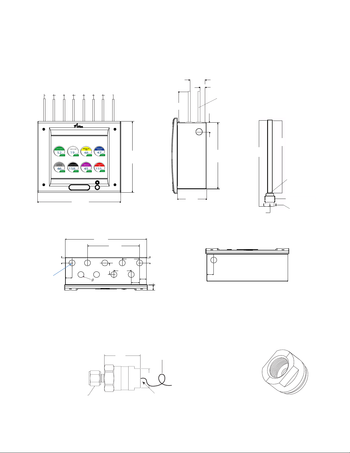
Dimensions
LCD ALARM
Front View
1.2
[30.48]
Top View
.75
[19.05]
Punched hole for
electrical power cord
[30.48]
2 1/10
Side View
1.2
1.2
1.2
1.2
1.2
[30.48]
[30.48]
[30.48]
[30.48]
[30.48]
1.2
7 3/16
[182]
10.25
[260.35]
[53.34]
0.81
[20.57]
Only supplied with Local
Sensors 3/8” [9.53mm] (O.D.)
1/4” [6.4mm] (I.D)
Type “K” Copper Pipe
1 1/4
[32]
9
[228.6]
7.50
[191]
NOTE: DISS demand check
valves by 1/4” NPT, supplied
with each sensor
6.375
[162]
Inch
[mm]
Brazing Filler
Metal AWS Spec.
BAg-7
[25.4]
12
[304.8]
10.7
[271.78]
1
0.875
[22.23]
1.75
[63.5]
7.5
[190.5]
2.5
[44.45]
[63.5]
2.5
1.2
[30.48]
[25.4]
.75
[19.05]
1
.75
[19.05]
3.97
[100.84]
Bottom View
1.25
[31.75]
1/4[6] NPT
1/2-14NPSM THD.
Brass 1[25] HEX
ALERT-3 SENSOR
16 Amico Pipeline
DISS
Connector
1.88
[48]
(Approximate, can vary)
#22 Gauge twisted pair
shielded cable 6”-8”
[0.1m - 0.2 m] supplied
Wrench Flats
1
[25]
1/2” Conduit
Connection
1/2”-14 NPSM [13]
Page 17

Troubleshooting
Symptom Cause Corrective Action
An error or “LOW ALARM” LCD screen The Microprocessor detected a fault and
has shut down
Faulty wire connection between the
sensor and LCD module
No power on the alarm AC power not available a. Ensure that the ON/OFF switch on
Fuse is blown Check the fuse. The fuse is located on the
DC power plug not connected to the LCD
module
Turn power switch to OFF position. Wait
for at least 5 seconds before turning ON
the power. The program will reset itself.
Check wiring diagram in Appendix D and
Appendix E
the power supply module is turned
ON (see Appendix B).
b. AC wiring not connected.
c. Check the building electrical breaker
to ensure that the power is ON.
d. Check the voltage at the terminal
block above the transformer. Ensure
that 115 VAC to 220 VAC is being
supplied.
upper-right corner of the system power
supply. Replace the fuse if it is defective
(see Appendix B and Appendix G).
a. Ensure that the DC power plug
is rmly in its socket on the LCD
module.
b. Replace the System Power Supply
unit if all the above steps fail to
resolve the problem.
Power light is ON, however there is no
display on LCD screen
No audible alarm DC power cable is disconnected, loose or
Audible signal will not silence Faulty display module Disconnect the ribbon cable from the
Loose ribbon cable from LCD screen to
board
check ribbon cable
Connection of the DC power cable from
system power supply to LCD module is
loose
Faulty push button Replace the LCD module.
a. Ensure that the cable is rmly in it’s
socket on the LCD screen and board.
b. Replace the LCD module.
a. Ensure that the DC power cable from
the system power supply is rmly
connected to the LCD module.
b. Replace LCD board.
back of the faulty display module and
replace the LCD module.
Disconnect the DC power cable from
the LCD module and then reconnect. If
audible alarm still persists, replace the
System Power Supply unit.
www.amico.com 17
Page 18

Troubleshooting
Symptom Cause Corrective Action
Gas reading incorrect Loose connection of DISS ttings Ensure that the sensor module is properly
connected to the DISS demand checkvalve
Sensor module is not properly wired to
the display module
Defective sensor or requires calibration Replace the sensor module
Defective LCD display module Replace the LCD display module
Display shows “NO SENSORS” No sensor(s) are connected to the LCD
board
Program not set up Press setup and select button to program
Faulty sensors Replace sensors
Ensure that the sensor module is properly
wired to the LCD module by using wiring
diagram in Appendix D or Appendix E
Make sure sensor module(s) are
connected to LCD board (see Appendix D
and Appendix E).
all connected sensors (see LCD Display
Set-Up in Section 9)
FACTORY DEFAULT SETTING GAS
Mid Pressure Hi = 60 psi
Low = 40 psi
Vacuum Hi = 32 inHg
Low = 12 inHg
High Pressure Hi = 195 psi
Low = 140 psi
18 Amico Pipeline
Page 19

Appendix A
AC Supply
115 to 220 VAC
DC Power Cable:
Connect to
Annunciator Module
G
N
L
Fuse (1 AMPw)
Toggle Switch
WIRING DIAGRAM: LCD MOTHERBOARD
DC Connector
Mute Button
(located on reverse side of board)
LCD Cable
Connector
Reset Button
Buzzer
CHANGE DOWN
SELECT/MUTE
B4 B3 B2 B1
CHANGE UP
SETUP
Sensor Terminal
12V DC
Output
LCD Power
Microchip
SD Card
Four Push
Buttons
Dry Contacts
(to Building Management System/Master)
www.amico.com 19
Page 20

Appendix B
L - Live
N - Neutral
G - Ground
Ground
WIRING DIAGRAM: AUTO-SWITCH POWER SUPPLY
AC Supply
115 to 220 VAC
Toggle Switch
Toggle Switch
AC Supply
115 to 220 VAC
G
N
L
L - Live
N - Neutral
G - Ground
Ground
Fuse (1 AMPw)
Fuse (1 AMPw)
DC Power Cable:
Connect to LCD
Module
20 Amico Pipeline
DC Power Cable:
Connect to
Annunciator Module
Page 21

Appendix C
AC Supply
115 to 220 VAC
DC Power Cable:
Connect to
Annunciator Module
G
N
L
Fuse (1 AMPw)
Toggle Switch
NO COM NC 12V GND
WIRING DIAGRAM: LCD DISPLAY MODULE - ALARM BUZZER
NO COM NC 12V GND
CHANGE DOWN
SELECT/MUTE
CHANGE UP
SETUP
B4 B3 B2 B1
NO COM NC 12V GND
www.amico.com 21
Page 22

Appendix D
AC Supply
115 to 220 VAC
DC Power Cable:
Connect to
Annunciator Module
G
N
L
Fuse (1 AMPw)
Toggle Switch
# 22 Gauge twisted
pair shielded cable
6”-8” [0.1m-0.2m] supplied
WIRING DIAGRAM: LCD DISPLAY MODULE - LOCAL SENSOR
Sensor
Module
OXYGEN
#22 Gauge twisted
pair shielded cable
6” - 8” [0.15m - 0.2m]
supplied
Black
CHANGE DOWN
SELECT/MUTE
CHANGE UP
B4 B3 B2 B1
SETUP
Red
22 Amico Pipeline
Page 23

AC Supply
115 to 220 VAC
DC Power Cable:
Connect to
Annunciator Module
G
N
L
Fuse (1 AMPw)
Toggle Switch
Appendix E
WIRING DIAGRAM: LCD DISPLAY MODULE - REMOTE SENSOR
# 22 Gauge twisted
pair shielded cable
6”-8” [0.1m-0.2m] supplied
OXYGEN
#22 Gauge twisted pair
shielded cable
100’ [30.5 m] max.
SELECT/MUTE
CHANGE DOWN
CHANGE UP
SETUP
Black
Red
Note:
For multiple sensors, a
multi-conductor shielded
twisted pair cable should
be used
B4 B3 B2 B1
www.amico.com 23
Page 24

Appendix F
AC Supply
115 to 220 VAC
DC Power Cable:
Connect to
Annunciator Module
G
N
L
L - Live
N - Neutral
G - Ground
Fuse (1 AMPw)
Ground
Toggle Switch
WIRING DIAGRAM: LCD DISPLAY MODULE - MASTER MODULE
#22 Gauge twisted
pair shielded cable
100’ [30.5 m] max.
Remote location
Alarm
#22 Gauge twisted
pair shielded cable
5,000' [1,500m] max.
Sensor
Module
DISS
Black
OXYGEN
Junction Box
(by others)
Red
#22 Gauge twisted
pair shielded cable
6"-8” [0.1 m-0.2 m]
supplied
Master
Module
CHANGE DOWN
SELECT/MUTE
B4 B3 B2 B1
CHANGE UP
To Amico: Master
Module or Building
Management System
SETUP
NC
C
NC
C
NC
C
NC
C
NC
C
NC
C
NC
C
NC
C
Source
Equipment
U 6 U 5
U 2
U4
U3
U4
10
123
4
ON
S1 S2
123456789
ON
++
+
C H 1 C H 2 C H 3 C H 4 C H 5 C H 6 C H 7 C H 8 C H 9 C H 1 0
+++++++
NOTE:
Jumper any unused points on
the Master module
24 Amico Pipeline
Turn OFF dip-switches for any
unused points (Location SW-2)
Page 25

Appendix G
TECHNICAL SPECIFICATIONS
Supply Voltage: 115 - 220 VAC, 50 - 60 Hz
Current Draw: 1 Amp. Max.
Fuse (1/4 * 1-1/4): Fast Blow 1 Amp.
Cable requirement:
LCD Alarm to Remote Sensor:
Important:
Cable: Belden # 8451 or equivalent. #22 gauge shielded, twisted pair. (For multiple
sensors a multi-conductor twisted pair, shielded cable should be used).
Distance: Maximum 100 ft [30.5 m]
Signal: 30 VDC - 1.0 Amps.
60 VDC - 0.3 Amps.
125 VAC - 0.5 Amps.
LCD Alarm to Master:
Distance: Maximum 10,000 ft [3,000 m]
Cable: Minimum #22 gauge wire
Signal: 5 VDC - 5.0 Amps.
LCD Generic Alarm:
Output: Dry Contacts NC, open on Alarm.
Rating: 30 VDC - 1.0 Amps.
60 VDC - 0.3 Amps.
125 VAC - 0.5 Amps.
www.amico.com 25
Page 26

26 Amico Pipeline
Page 27

www.amico.com 27
Page 28

www.amico.com
Amico Pipeline | www.amico.com
85 Fulton Way, Richmond Hill
Ontario, L4B 2N4, Canada
Toll Free Tel: 1.877.462.6426
Toll Free Fax: 1.866.440.4986
Tel: 905.764.0800
Fax: 905.764.0862
Email: info@amico.com
A3-MAN-LCD-ENG 11.12.2013
 Loading...