

Page 1
INSTRUCTIONS FOR USE
GB
Kitchen extractor hood
Type: OKC 6767 I
IO 00204
Page 2
Dear Customer
You are now a user of t he n ew es t ge ner ation kitch en
extractor hood of OKC 6767 I type.
This hood has been designed and manufactured specially
with a view to satisfying your expectations and it will certainly
constitute a fitting element of a modern kitchen. The modern
structural solutions and the newest technologies used in
production of this hood guarantee its high effectiveness and
good appear ance.
Please read these instructions carefully before installing
the hood. They will make you avoid mist akes during
installation and operation of the hood.
We wish you a lot of satisfaction from choosing our
kitchen extractor hood.
I Characteri st ics
II Components
III Technical data
IV Operating conditions
V Installation
VI Operation and maintenance
CONTENTS
3
3
3
4
5
6
2
Page 3
I Characteristics
OKC 6767 I kitchen extractor hood was designed to remove kitchen fumes. It
requires installation of a cond uit discharging used air to the outs i de. The conduit
(usually a pipe Ø150 or 120 mm) shal l not be longer than 4-5 m. The hood can
operate as an od our absorber aft er installation of an ac tive carbon filter . In such case
a conduit discharging used air to the outside is not necessary, but it is recommended
to install an air ex haust guide.
The kitchen hood is an electrical appliance man ufactured according to class II of
shock protec tion.
It has its own light ing and an exhaust fan which can be set to one of three rot ational
speeds.
The hood was des igned for permane nt installatio n on a vertical wall over a gas or
electric cook er .
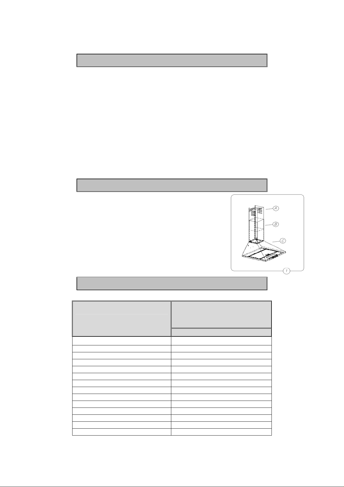
II Components
The hood consist s of the following elements (Fig. 1):
1) Hood body with a glass [C], equip ped with lights , the
fan unit and cass ette-type metal filters
2) The telescopic masking cover consisting of the top
funnel A and the bot tom funnel B,
3) Set of mounting plugs
III Technical data
Characteristics
Supply voltage AC 230 V ~50 HZ
Fan motor 1
Lighting 2 x 40 W
Number of grease filters 2
Fan speeds 3
Width [cm] 60
Depth [cm] 50
Height [cm] 69-112,5
Outlet [ø mm] 120
Capacity [m 3/h] 620
Power consumption [W] 200
Noise level [dBA] 54
Net weight [kg] 8,6
Operational mode Extractor or absorber
3
Type
OKC 6767 I
Page 4
IV Operating conditions
1. The kitchen hood was designed for removal of kitchen fumes to the outside. It
should be conn ected to an appropriat e ventilation duct (do not c onnect the hood to
any chimney, s m oke or flue-gas ducts which are in use).
2. The device shall be ins talled at the distance of at least 65 0 mm above the working
top of an electric c ooker and 700 mm - of a gas cooker.
3. Do not leav e open flame under t he hood. When remov ing pots from the bur ners
set the flame to its minimum level.
4. Any food cooked in fat shall be constantly monitored, since overheated fat can
ignite very easily.
5. The grease f ilter of your kit chen hood sh ould be cl eaned at least ev ery 2 months ,
because a filter s oaked with grease becomes easily flammable.
6. Pull the plug of the power cord from a wall socket before any cleaning, filter
replacement or repair operation.
7. W hen connecti ng to 2 30V po wer suppl y net work use an electr ic sock et i n work ing
order
WARNING: before you connect the hood to t he power supply and check whether it
works properl y, you will alw ays need t o control if the wire has b een proper ly ins talled
and if it has NOT been pinned down by the hood while it was being mounted.
8. If the power wir e gets broken, it should be repl aced with a new one in a specialist
repair shop.
9. The device was protected against damage for the time of transport. After
unpacking, please remove the elements of packaging in an environment-frie ndly way.
All materials used for packaging are env ironment friendl y, they can be 100% recycled
and they hav e been marked with appropriate symbols.
Warning! The packaging materials (polyethylene bags, small pieces of foamed
polystyrene etc.) should be kept away from chi ldren while unpacking.
4
Page 5

V Installation
To install t he hood proceed as foll ows :
1. Hang the hood body,
2. Connect the hood to the ventilat ion duct,
3. Establish the hei ght of the telescoping column of the
masking cover,
4. Install the wa ll hanger at the appropriate level,
5. Install the complete set of masking c overs,
6. Connect the hood to the power supply network .
1.1. Moun ting the Wall Hanger
1. Draw a vertical line on the wall to mark the centre of t he c ooker. Hold the body
of the cooker hood against the wall a nd arrange it sym m etrically with the
centre line, keeping a distance of at least 790 mm between the openings in
the hood body and t he hotplate. Holding it level, mark the spacing of the
mounting holes on the wall,
2. Drill the holes m ar ked on the wall usin g a dr ill head with a dia meter equal to
that of the rawlplugs supplied, then hammer the p lugs in and screw the body
of the hood onto the wall,
1. If necessary, install the appropriate air outlet
1.2. Assemb ling the Hood
leading to a ventilation duct ,
2. Place the teles c opic column of t he frame A and B
onto the hangi ng hood (fig. 1)
3. Slide the upper frame (fig.3) to the required height,
mark its maximum span on the centre line, then
remove the column of the frame,
4. Hold hanger D of the upper frame (f ig. 3) against
the marked centre line, then mark the positions of
the hanger’s mo unting holes on the wall and attach
it. Replace th e c olumn of the frame and screw it
onto the upper hanger of the fr ame (f ig. 3 pt B & C)
using the appr opr iate screws
5. Connect the hood to the electric ity mains. Fig. 3
5
Page 6

After connecting the device to the power supply network (in accordance with the
requirements defined above) it is necessary to check the lighting of the hood and
whether its motor works correctly.
The wall socket shall be accessible for disconnecting the plug after the hood is
installed.
1.3. Conn ecting to the power network and o peration check
1.4. Setting the operation mode of the kitchen extractor hood
1.4.1. Setting the air extractor mode of operation of the hood
In the extractor mode air is discharged to the outside by a special conduit. In that
setting any carbon filters shall be removed.
The hood can be connecte d to the o pening disc harging air t o the outsid e by means
of a rigid or flexible c onduit of 15 0 or 120 mm d iameter, and a ppropriate c lamps for
conduits which should be purch as ed in a shop selling installation mater ials.
A qualified ins taller should be commissioned to make the connecti on.
1.4.2. Setting the odour absorber mode of operation of the hood
In this option filtered air returns to the room through cut outs on both sides of the
bottom funnel.
In this setting it is necessary to install the carbon filter
1.4.3. Fan speeds
The lowest and medium speeds should be used under normal conditions and with
low concentration of fumes. The top speed should be used in case of high
concentrati on of kitchen fumes , e.g. during fr yin g or gr illing.
VI Operation and maintenance
1.1. Operational safety
All safety instructions included in this manual s hall be observed without except ion!
Grease filters and active carbo n filters s hould be cleaned a nd replaced acc ording to
manufactur er’s inst ruct i ons, or more f reque ntl y in per iods of i ntens iv e use ( mor e tha n
4 hours a day).
If a gas cook er is us ed it is f orb idd en t o le av e uncov ered f lame. When remo v ing pots
from gas burner s s et the flame to its mi nimum level.
Always make sure that flame does not extend outside the pot. Such a situation
causes undes ir ed energy losses and dangerous heat build-ups.
The hood should not be used for other purposes than those for which it was
designed.
6
Page 7

1.2. Operation
1.2.1. Control panel
Operation of the hood can be controlled by means of a combined switch (Fig. 6)
- „1” – first speed of hood motor on,
- „2” – second speed of hood motor on,
- „3” – third speed of hood motor on,
- „0” – motor off,
- „L” – lighting on / off.
Fig 6
1.3. Maintenance
Regular maint enance and cleaning of the devic e will guarantee its good and fault less operation, and extend its life. Attention should be paid to replacing grease and
carbon filters according to man ufacturer’s instructions.
1.3.1 Metal grease filters
1. Cleaning.
Grease filters s hould be cleane d every two months dur ing normal operation of the
hood, in a dishwas her or manually, using mild det er gent or liquid soap.
2. Replaceme nt (Fig. 7).
To dismantle the filter proceed as
follows:
a) remove the bottom cover by
releasing th e loc k catch,
b) remove the metal grease filter
7
Page 8

1.3.2. Carbon filter
1. Operation.
Carbon filters c an be used only when the hood is not con nec ted to any ventilation
duct. Filter s with active carbon can absorb odours until they are satur ated. They
cannot be wash ed or r egenerated and should be replaced at least ever y 2 m onths or
more frequent ly in case of ver y intens ive use.
2. Active car bon filter replace me nt.
a) Remove metal grease f ilter (Fig.8 a, b, c)
b) Put a new active car bon filter on the metal grease filter
1.3.3. Lighting
To replace lig ht bulb proceed as follows:
d) Disconnect power supply to the hood
e) Remove the grease filter .
f) Replace the bulb using a piece of c l oth or paper for that purpose.
g) Reinstall the grease filter.
1.3.4 Cleaning
The following shall be avoided during normal cleaning of the hood:
• wet cloth or sponge a nd water jet,
• solvents or alcohols which might dull l ac quered surfaces ,
• caustic agents, par ticularly in regar d to cleaning s tainless steel el ements,
• hard, rough cloth
It is recommended to us moist clot h and neutral cle aning agents.
8
Page 9

9
Page 10

10
Page 11

11
Page 12

Disposing of the device
When disposi ng of the device, do not bring it to regular municipal waste containers.
Instead, bring it to electrical a nd electronic waste recycling and reuse center. A
relevant lab el has been put on the dev ice, its instruct ions manual, or on the pac kage.
The devic e has been manufacture d of recyclable mater ials. By bringing old device t o
recycling collection center, you show that you c ar e about nature.
Ask your local environmental car e authority for inf ormation on locat ion of such
facilities.
Manufacturer’s declaration
The manufacturer hereby decl ar es that the applianc e fulfils the requirements of the
following Eur opean directiv es :
The Low Voltage Directive 2006/95/EC,
The Electr oma gnetic Compatibility Direct ive 2004/108/EC,
and therefore it has been marked with a
and assigned a declaration of
conformit y, whic h is made available to the market super vising authorit ies.
12
 Loading...