

Page 1

Olympus III
User’s Guide
MAN-875
02/02/04
Page 2

© Copyright 1985-2010 American Megatrends, Inc.
All rights reserved.
American Megatrends, Inc.
5555 Oakbrook Parkway, Building 200,
Norcross, GA 30093
This publication contains proprietary information which is protected by copyright. No
part of this publication can be reproduced, transcribed, stored in a retrieval system,
translated into any language or computer language, or transmitted in any form
whatsoever without the prior written consent of the publisher, American Megatrends, Inc.
American Megatrends, Inc. acknowledges the following trademarks:
Intel is a registered trademark of the Intel Corporation.
MS-DOS and Microsoft are registered trademarks of the Microsoft Corporation.
Microsoft Windows is a trademark of the Microsoft Corporation.
IBM, AT, VGA, PS/2, and OS/2 are registered trademarks and XT and CGA are
trademarks of the International Business Machines Corporation.
Other trademarks and trade names may be used in this document to refer to either the
entities claiming the marks and names or their products. American Megatrends, Inc.
disclaims any proprietary interest in trademarks and trade names other than its own.
Revision History
10/31/03 Initial release.
02/02/04 Added required FCC Class A statement.
American Megatrends, Inc., Olympus III User’s Guide (Series 875)
ii
Page 3

Table of Contents
Chapter 1 Hardware Specifications and Supported Features ................................................ 1
Overview ...................................................................................................................................... 1
Specifications............................................................................................................................... 1
Board Layout................................................................................................................................ 3
Rear I/O Ports .............................................................................................................................. 4
Block Diagram.............................................................................................................................. 5
Supported Processors ................................................................................................................. 6
Supported System Memory .........................................................................................................6
More Features.............................................................................................................................. 7
Faster, 128-bit dual channel DDR 400 memory support ......................................................... 7
800 MHz FSB CPU support (200 MHz quad-pumped) ............................................................ 7
Serial ATA (SATA) support ...................................................................................................... 8
ICH ........................................................................................................................................... 8
AGP 8X..................................................................................................................................... 8
Integrated hi-speed USB 2.0.................................................................................................... 8
Enhanced AC '97 Audio ...........................................................................................................8
Error Correction Code .............................................................................................................. 9
Hyper-Threading Technology................................................................................................... 9
478-pin Processor Package Compatibility ............................................................................... 9
Intel Performance Acceleration Technology (PAT).................................................................. 9
Communications Streaming Architecture (CSA)...................................................................... 9
Low-Power Sleep Mode ........................................................................................................... 9
Chapter 2 Hardware Installation............................................................................................... 11
Overview .................................................................................................................................... 11
Motherboard Installation ............................................................................................................ 11
Rear I/O Ports ............................................................................................................................ 11
Motherboard Layout................................................................................................................... 12
Step 1 Unpack the Motherboard................................................................................................ 13
Avoid Electro-Static Discharge (ESD).................................................................................... 13
JP10 Clear CMOS.................................................................................................................. 14
Step 2 Install Memory ................................................................................................................ 15
Memory Overview .................................................................................................................. 15
Supported Memory................................................................................................................. 16
Memory Configuration ............................................................................................................16
Highest Throughput Level (RECOMMENDED) ..................................................................... 17
Second Highest Throughput Level......................................................................................... 17
Second Lowest Throughput Level.......................................................................................... 18
Lowest Throughput Level....................................................................................................... 18
Inserting DIMM Modules ........................................................................................................ 19
Removing DIMM Modules...................................................................................................... 19
Step 3 Install CPU and Connect Heatsink and Fan................................................................... 20
Step 4 Install the Motherboard................................................................................................... 25
Step 5 Attach Internal Cables .................................................................................................... 27
CN1 and CN2 ATX Power Supply Connectors ...................................................................... 28
JP11 Wake On LAN connector .............................................................................................. 31
J1 ITP Connector ................................................................................................................... 32
J14 OEM BIOS Function ........................................................................................................ 33
J16 External Hard Disk Activity LED Connector .................................................................... 34
Preface
iii
Page 4

Table of Contents
J17 IPMB Connector ..............................................................................................................35
J18 BMC Debug Connector ................................................................................................... 36
J20 External Serial Port Connector........................................................................................ 37
J13 Floppy Drive Connector................................................................................................... 39
J6 and J7 IDE Connectors ..................................................................................................... 40
Ultra ATA-100/133.................................................................................................................. 41
CN4 and CN5 Serial ATA Connectors ................................................................................... 42
Serial ATA RAID..................................................................................................................... 43
RAID Boot............................................................................................................................... 43
J19 Front Panel Connector .................................................................................................... 44
J19 ATX Power Supply Soft ON/OFF Connector .................................................................. 45
J19 Reset Button Connector .................................................................................................. 45
J19 Parallel ATA Activity LED Connector .............................................................................. 46
J19 Intrusion Sensor Connector............................................................................................. 46
J19 Power LED Connector..................................................................................................... 47
J19 System Fault LED Connector.......................................................................................... 47
Step 6 Install Expansion Boards................................................................................................ 50
AGP Slot................................................................................................................................. 50
PCI Slots................................................................................................................................. 51
PCI IRQ Routing Table...........................................................................................................51
Step 7 Connecting External Cables........................................................................................... 53
LAN Connector....................................................................................................................... 57
Serial Port Connector ............................................................................................................. 58
VGA Connector ...................................................................................................................... 59
Line In Audio Jack .................................................................................................................. 60
Speaker Out Audio Jack ........................................................................................................ 61
Microphone Audio Jack .......................................................................................................... 62
Step 8 Install Drivers.................................................................................................................. 62
Step 9 Test and Configure......................................................................................................... 62
Chapter 3 AMIBIOS Setup.........................................................................................................63
Overview .................................................................................................................................... 63
Starting AMIBIOS Setup ............................................................................................................ 63
AMIBIOS Setup Menu ............................................................................................................ 64
Section 1 Main Setup................................................................................................................. 65
Section 2 Advanced Setup......................................................................................................... 66
CPU Configuration ................................................................................................................. 66
L3 Cache ................................................................................................................................ 67
Hyper Threading Technology................................................................................................. 67
IDE Configuration ................................................................................................................... 67
S-ATA Running Enhanced Mode ........................................................................................... 68
P-ATA Channel Selection....................................................................................................... 69
Combined Mode ..................................................................................................................... 69
S-ATA Ports Definition ........................................................................................................... 69
Configure S-ATA as RAID...................................................................................................... 69
Hard Disk Write Protect.......................................................................................................... 69
IDE Detect Time Out (Sec)..................................................................................................... 70
ATAPI 80 Pin Cable Detection ............................................................................................... 70
Primary and Secondary IDE Master : Hard Disk Drive .......................................................... 71
Primary and Secondary IDE Master : ATAPI CD ROM ......................................................... 72
Type........................................................................................................................................ 72
American Megatrends, Inc., Olympus III User’s Guide (Series 875)
iv
Page 5

Table of Contents
LBA/Large Mode .................................................................................................................... 73
Block (Multi-Sector Transfer) ................................................................................................. 73
PIO Mode ............................................................................................................................... 73
DMA Mode.............................................................................................................................. 74
S.M.A.R.T. for Hard Disk Drives ............................................................................................ 74
32Bit Data Transfer ................................................................................................................ 75
ARMD Emulation Type........................................................................................................... 75
Third and Forth IDE Slave...................................................................................................... 75
Floppy Configuration .............................................................................................................. 75
Floppy A ................................................................................................................................. 76
Floppy B ................................................................................................................................. 76
SuperIO Configuration............................................................................................................ 76
Onboard Floppy Controller..................................................................................................... 76
Serial Port1 Address .............................................................................................................. 77
Serial Port2 Address .............................................................................................................. 77
Serial Port2 Mode................................................................................................................... 78
IR Duplex Mode...................................................................................................................... 78
IR Receiver Pin ...................................................................................................................... 78
Parallel Port Address.............................................................................................................. 79
Parallel Port IRQ .................................................................................................................... 79
ACPI Configuration................................................................................................................. 80
Advanced ACPI Configuration ............................................................................................... 80
ACPI 2.0 Support ................................................................................................................... 81
ACPI APIC Support ................................................................................................................ 81
APIC SCI IRQ......................................................................................................................... 81
BIOS-->AML ACPI Table ....................................................................................................... 81
Headless Mode ...................................................................................................................... 81
DMI Event Logging................................................................................................................. 82
Hardware Health Configuration.............................................................................................. 85
HW Health Function ............................................................................................................... 85
Hardware Health Event Monitoring ........................................................................................ 85
MPS Configuration ................................................................................................................. 86
MPS Revision......................................................................................................................... 86
Remote Access Configuration................................................................................................ 87
Remote Access ...................................................................................................................... 87
Serial Port Number................................................................................................................. 88
Serial Port Mode..................................................................................................................... 88
Flow Control ........................................................................................................................... 88
Redirection After BIOS POST ................................................................................................ 88
Terminal Type ........................................................................................................................ 88
VT-UTF8 Type Combo Key Support ...................................................................................... 89
USB Configuration.................................................................................................................. 89
USB Function ......................................................................................................................... 90
Legacy USB Support..............................................................................................................90
USB 2.0 Controller ................................................................................................................. 90
USB 2.0 Controller Mode ....................................................................................................... 90
Section 3 PCI/PnP Setup........................................................................................................... 91
Plug and Play O/S .................................................................................................................. 91
PCI Latency Timer.................................................................................................................. 91
Allocate IRQ to VGA............................................................................................................... 92
Palette Snooping .................................................................................................................... 92
Preface
v
Page 6

Table of Contents
PCI IDE BusMaster ................................................................................................................ 92
Onboard PCI IDE Card........................................................................................................... 93
IRQ 3, 4, 5, 9, 10, 11, 14, and 15........................................................................................... 93
DMA Channel 0, 1, 3, 5, 6, and 7........................................................................................... 93
Reserved Memory Size.......................................................................................................... 94
Section 4 Boot Setup ................................................................................................................. 95
Boot Settings Configuration ................................................................................................... 95
Quick Boot .............................................................................................................................. 96
Quiet Boot............................................................................................................................... 96
AddOn ROM Display Mode .................................................................................................... 96
Bootup Num-Lock................................................................................................................... 96
PS/2 Mouse Support ..............................................................................................................96
Wait For 'F1' If Error ............................................................................................................... 96
Hit 'DEL' Message Display ..................................................................................................... 97
Interrupt 19 Capture ............................................................................................................... 97
Boot Device Priority................................................................................................................ 97
st
1
Boot Device ....................................................................................................................... 98
nd
2
Boot Device ...................................................................................................................... 98
rd
3
Boot Device ....................................................................................................................... 98
th
4
Boot Device ....................................................................................................................... 98
th
5
Boot Device ....................................................................................................................... 98
Hard Disk Drives Boot Priority................................................................................................ 99
Removable Drives Boot Priority ........................................................................................... 100
CD/DVD Drives Boot Priority................................................................................................ 101
Section 5 Security Setup.......................................................................................................... 102
Setting Up a Supervisor Password ...................................................................................... 102
Clearing the Password (via BIOS) ....................................................................................... 105
Clearing the CMOS (via Hardware Jumper) ........................................................................ 108
Section 6 Chipset Setup .......................................................................................................... 108
NorthBridge Chipset Configuration ...................................................................................... 109
DRAM Frequency................................................................................................................. 109
Configure DRAM Timing by SPD ......................................................................................... 109
DRAM Integrity Mode ........................................................................................................... 110
Memory Hole ........................................................................................................................ 110
Primary Graphics Adapter.................................................................................................... 110
Graphics Aperture Size ........................................................................................................ 110
CSA Gigabit Ethernet ........................................................................................................... 111
Onboard VGA Configuration ................................................................................................ 111
South Bridge Chipset Configuration..................................................................................... 111
Onboard AC’97 Audio .......................................................................................................... 111
Section 7 Power Management................................................................................................. 112
Power Management/APM .................................................................................................... 112
Video Power Down Mode..................................................................................................... 113
Hard Disk Power Down Mode .............................................................................................. 113
Standby Time Out ................................................................................................................113
Suspend Time Out (Minute) ................................................................................................. 114
Throttle Slow Clock Ratio ..................................................................................................... 114
Keyboard & PS/2 Mouse ...................................................................................................... 114
FDC/LPT/COM Ports............................................................................................................ 114
Primary Master IDE ..............................................................................................................114
Primary Slave IDE ................................................................................................................ 114
American Megatrends, Inc., Olympus III User’s Guide (Series 875)
vi
Page 7

Table of Contents
Secondary Master IDE ......................................................................................................... 114
Secondary Slave IDE ........................................................................................................... 114
System Thermal ................................................................................................................... 115
System Thermal Active Temperature................................................................................... 115
Thermal Slow Clock Ratio .................................................................................................... 116
Power Button Mode.............................................................................................................. 116
Restore on AC Power Loss.................................................................................................. 116
Resume on Ring, LAN, PME#, and RTC Alarm................................................................... 117
Section 8 Exit ........................................................................................................................... 117
Exit Saving Changes ............................................................................................................ 118
Exit Discarding Changes...................................................................................................... 118
Discard Changes.................................................................................................................. 119
Load Optimal Defaults.......................................................................................................... 119
Load Failsafe Defaults..........................................................................................................120
Chapter 4 Programming Flash ROM...................................................................................... 121
A) Programming the Flash EPROM Using <Ctrl> <Home>................................................. 121
Bootblock Actions................................................................................................................. 121
S875P.ROM ......................................................................................................................... 122
Beep Codes.......................................................................................................................... 122
B) Programming the Flash EPROM Using the AMIFlash Utility .......................................... 123
Bootblock Code Checkpoint Codes......................................................................................... 126
Chapter 5 Deleting a Password.............................................................................................. 127
Overview .................................................................................................................................. 127
Erase Old Password ................................................................................................................ 127
Appendix A Battery Replacement....................................................................................... 129
Battery...................................................................................................................................... 129
Appendix B AMIBIOS Beep Codes ..................................................................................... 131
Troubleshooting AMIBIOS Beep Codes .................................................................................. 131
Index ........................................................................................................................................... 133
Preface
vii
Page 8

Limited Warranty
The buyer agrees that if this product proves to be defective, American Megatrends is
only obligated to repair or replace this product at American Megatrends’ discretion
according to the terms and conditions of the warranty registration card that accompanies
this product. American Megatrends shall not be liable in tort or contract for any loss or
damage, direct, incidental or consequential resulting from the use of this product. Please
see the Warranty Registration Card shipped with this product for full warranty details.
Technical Support
AMI provides technical support for AMI products purchased directly from AMI or from
an AMI-authorized reseller only.
If… Then…
You purchased this product from AMI or
from a certified AMI reseller,
This AMI product was installed as part
of a system manufactured by a company
other than AMI or you purchased an
AMI product from an unauthorized
reseller,
If your American Megatrends Olympus III motherboard fails to operate as described or
you are in doubt about a configuration option, please call technical support at 770-246-
8645.
Web Site
We invite you to access the American Megatrends World Wide Web site at:
http://www.ami.com/
Call AMI technical support at 770-246-
8645. Please be prepared to specify the
serial number of the product.
Call the technical support department of
the computer manufacturer or the
unauthorized reseller. AMI does not
provide direct technical support in this
case.
American Megatrends, Inc., Olympus III User’s Guide (Series 875)
viii
Page 9

Disclaimer
This manual describes the operation of the American Megatrends Olympus III
motherboard. Although efforts have been made to assure the accuracy of the information
contained here, American Megatrends expressly disclaims liability for any error in this
information, and for damages, whether direct, indirect, special, exemplary, consequential
or otherwise, that may result from such error, including but not limited to the loss of
profits resulting from the use or misuse of the manual or information contained therein
(even if American Megatrends has been advised of the possibility of such damages). Any
questions or comments regarding this document or its contents should be addressed to
American Megatrends at the address shown on the inside of the front cover.
American Megatrends provides this publication “as is” without warranty of any kind,
either expressed or implied, including, but not limited to, the implied warranties of
merchantability or fitness for a specific purpose.
Some states do not allow disclaimer of express or implied warranties or the limitation or
exclusion of liability for indirect, special, exemplary, incidental or consequential
damages in certain transactions; therefore, this statement may not apply to you. Also, you
may have other rights which vary from jurisdiction to jurisdiction.
This publication could include technical inaccuracies or typographical errors. Changes
are periodically made to the information herein; these changes will be incorporated in
new editions of the publication. American Megatrends may make improvements and/or
revisions in the product(s) and/or the program(s) described in this publication at any time.
Requests for technical information about American Megatrends products should be made
to your American Megatrends authorized reseller or marketing representative.
Retail Packing List
You should have received the following:
• an Olympus III motherboard
• a floppy drive cable
• two ATA-100/133 cables
• two Serial ATA cables
• an I/O shield
• a warranty card
• this Olympus III User's Guide (located on the Olympus III CD)
• an Olympus III Quick Installation Guide
• an Olympus III CD
Note: Your Olympus III (series 875) motherboard may or may not ship with everything listed
in the Retail Packing List. Contact your AMI authorized reseller to find out what is
shipped with your motherboard.
Preface
ix
Page 10

Optional Components
The following component does not come (mounted) with your Olympus III motherboard.
You must order these components separately.
• Hitachi® BMC chip
Note: The Hitachi® BMC chip is not mounted on your motherboard. This BMC chip is not
described in this manual. This is used strictly for OEM custom configurations. Contact
your American Megatrends OEM sales representative for custom OEM design services.
FCC Class A (USA)
This equipment has been tested and found to comply with the limits for a Class A digital
device, pursuant to part 15 of the FCC Rules. These limits are designed to provide
reasonable protection against harmful interference when the equipment is operated in a
commercial environment. This equipment generates, uses, and can radiate radio
frequency energy and, if not installed and used in accordance with the instruction
manual, may cause harmful interference to radio communications. Operation of this
equipment in a residential area is likely to cause harmful interference in which case the
user will be required to correct the interference at his own expense.
Shielded cables must be used with this unit to ensure compliance with the Class A FCC
limits.
American Megatrends, Inc., Olympus III User’s Guide (Series 875)
x
Page 11

Chapter 1 Hardware Specifications and
Supported Features
Overview
The AMI Olympus III motherboard utilizes the Intel 875P chipset. It offers support for
the latest Intel processors, including 800FSB, 8x AGP, Performance Acceleration
Technology (PAT), Hyper Threading technology, Dual-Channel DDR 400/333 SDRAM
memory with ECC Support, dual Parallel ATA, dual Serial ATA-150 RAID, Gigabit
LAN, and USB 2.0.
One of the biggest features of the Olympus III motherboard is its integration of the
onboard Gigabit Ethernet controller. The Gigabit Ethernet controller connects directly to
the Intel 875P chipset via a dedicated Communication Streaming Architecture (CSA) bus.
In the Olympus II motherboard, the onboard Ethernet controller connected to the south
bridge chipset via the PCI bus. The CSA bus is 64 bits wide, while the PCI bus is only 32
bits wide. Theoretically, the CSA bus has twice the bandwidth of a PCI bus. This
overcomes the bandwidth limitation found when running off of the PCI bus.
With all these features the Olympus III motherboard is the perfect fit for server
appliances such as, Network Attached Storage (NAS) and Mail/Web servers.
Specifications
Item Description
CPU
i875P
(Canterwood)
Intel Chipset
Memory
Slots
On-Board Video
On-Board LAN
• Single Pentium 4 and PGA 478 Socket
• 533/800 MHz FSB
• Hyper Threading supported
• GMCH, Memory Controller Hub, AGP8X Interface
• ICH5, I/O Controller Hub
• FWH, Firmware Hub Flash Interface
• Four DIMM Sockets
• 4 GB Max Memory Support
• Support for Dual Channel DDR333/400 SDRAM with ECC support
• Maximum Memory Throughout is ~3.2GB/s per channel
• Five 32-Bit 33 MHz PCI Slots
• One AGP 8X Slot
• ATI Rage XL
• Gigabit Fast Ethernet Controller: Intel 82547
• Supports ACPI 1.0b/2.0 Based Power Management
• Supports Wake on Magic Packet
• WFM 2.0 Compliant
• PCI 2.2 Compliant
• One RJ45 Port for External Connection
Cont’d
Chapter One : Hardware Specifications and Supported Features 1
Page 12

Specifications, Continued
Item Description
USB 2.0
Serial/
Parallel ATA
Standard I/O
IPMI BMC
Server
Management
Server
Management
Hardware
AMI Server
BIOS
Form Factor
Environmental
Specifications
BIOS
• Two Ports
• Dual Serial ATA Connectors
• Dual Parallel IDE Connectors ATA 100/133
• Port Angeles, Integrated Super I/O with Manageability Functions
• PS/2 Mouse
• Floppy, Parallel/Serial HDR
• Hardware Monitor: Hitachi H8-2168 BMC (Baseboard Management Controller)
• IPMI v1.5 Compliant
• AMI MegaRAC-PM Firmware
• General Purpose Non Volatile (GPNV) Storage
• Located in the FWH, used to store:
• BIOS POST Code
• System Boot Log
• CPU Temperature, FAN, ECC History
• Chassis Fan, Temperature History
• Event Log
• Hardware Monitor: HECETE4
• I2C Master Embedded in the Super I/O
• SMBus Controller Embedded in the ICH5
• System Monitors for the Following Devices:
• One Chassis Fan, Chassis Door Open Detection, 1 CPU Fan
• One Ambient Temperature Sensor
• CPU Core Voltages are Individually Monitored
• Voltage-Safe Operating Ranges Automatically Established for Different CPUs
• Slot Voltages and Chipset Voltages
• System I2C Information Displayed in BIOS Setup Screen
• SMBIOS 2.3 Complaint
• Event Logging for System Errors (POST and Runtime)
• DMI Compliant, ACPI Compliant
• Standard ATX
• Storage Temperature: -20 degrees to 80 Degrees C
• Relative Humidity: 5 to 80% Non-Condensing @40 Degrees
• Operating Temperature: 0 to 55 Degrees C
• Vibration: 2.5G Acceleration Over 2000 Hz Sine Wave, 2oct/Mian Sine Sweep
• Shock: 20G; 11 Msec Duration, Half-Sine Shock Sweep
• AMIBIOS8™
American Megatrends, Inc., Olympus III User’s Guide (Series 875)
2
Page 13
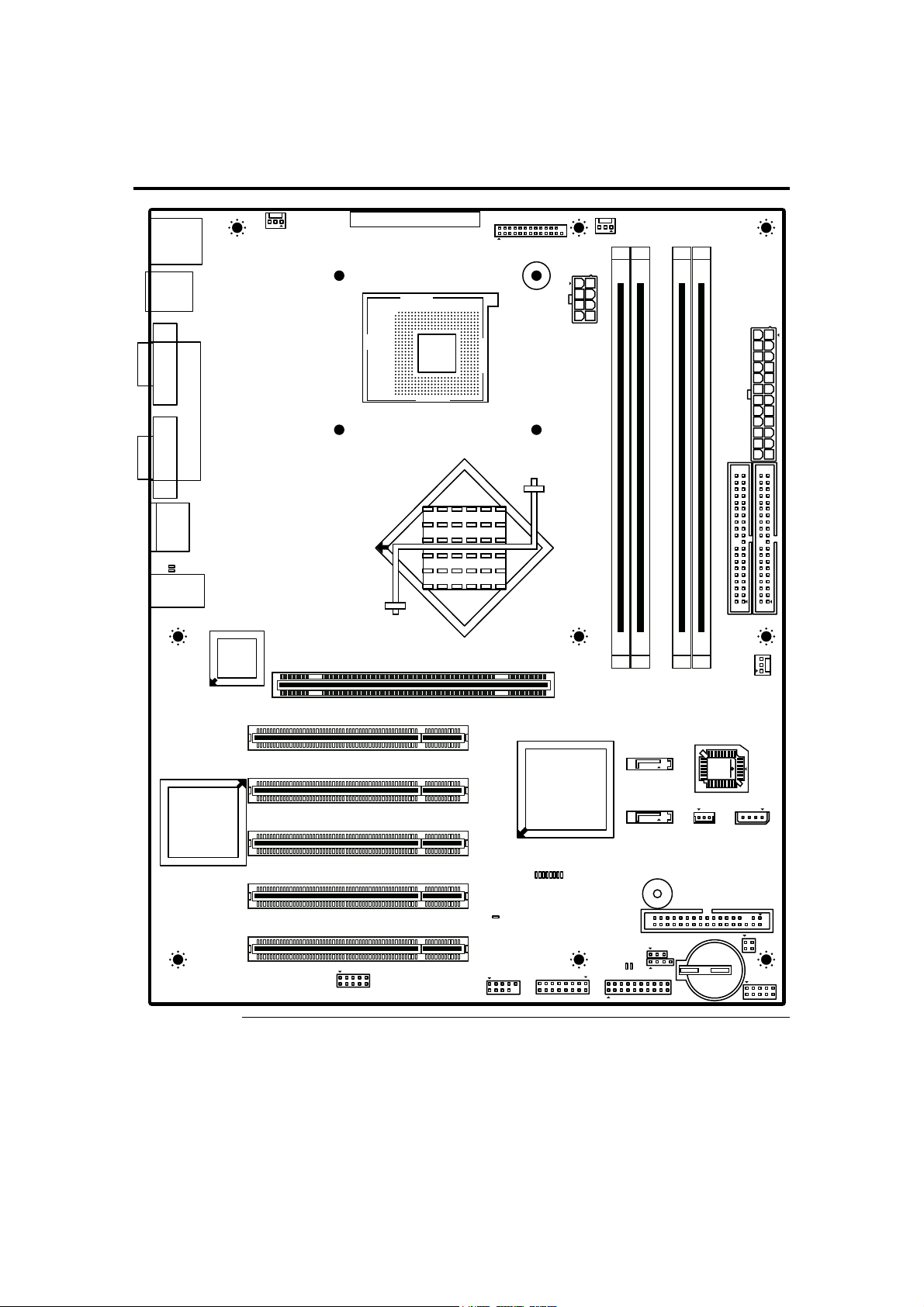
Board Layout
& MOUSE
PS2 KEYBOARD
SYSTEM FAN1
JP5
JP7
SERIAL NUMBER
AMERICAN MEGATRENDS INC.
(C) 2003 SERIES 875 REV-A1
J1 ITP
CPU FAN
JP1
JP2
USB 0&1
COM 1
VGA
RJ45
MIC IN
SPR OUT
D3
D2
LINE IN
PARALLEL
PCI SLOT 1
SOCKET 478
AGP SLOT
8PIN POWER
J2 DDR A DIMM 0
J3 DDR A DIMM 1
J4 DDR B DIMM 0
J5 DDR B DIMM 1
J6 SECONDARY IDE
SYSTEM FAN2
24PIN POWER
J5 PRIMARY IDE
JP6
JP8
SATA 1
PCI SLOT 2
SATA 0
PCI SLOT 3
D9
D10
D11
D12
D13
D14
D15
PCI SLOT 4
PCI SLOT 5
J20
D17
USB 2&3
D16
J18
BUZZER
J10
D19
D18
J16
J19
JP11 J17
J13 FLOPPY
J14
BATTERY
J21
Chapter One : Hardware Specifications and Supported Features 3
Page 14
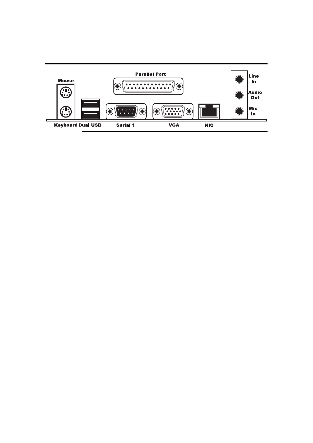
Rear I/O Ports
American Megatrends, Inc., Olympus III User’s Guide (Series 875)
4
Page 15
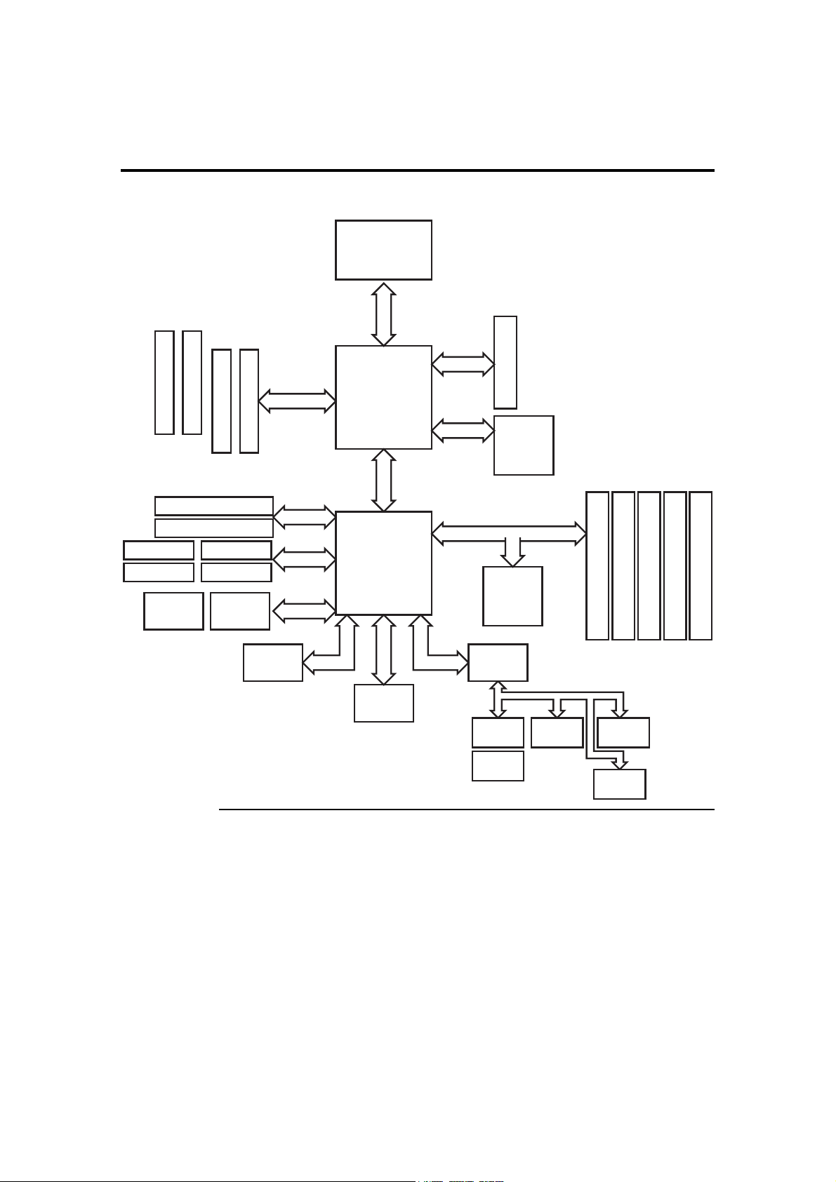
Block Diagram
The block diagram for the Olympus III is shown below:
DDR400 CHA DIMM 0
DDR400 CHA DIMM 1
DDR400 CHB DIMM 0
Primary IDE
Secondary IDE
USB 0
USB 1
Serial ATA 0 Serial ATA 1
USB 2
USB 3
Memory I/F
DDR400 CHB DIMM 1
Pentium 4 CPU
Socket 478
FSB 533/800 MHz
FSB
Canterwood (MCH)
HI 1.5LPC 1.0
ICH5
AGP 3.0
CSA I/F
PCI 2.3
4X/8X AGP
Kenai II CSA
Giga Ethernet
ATI VGA
RAGE XL
PCI Slot 1
PCI Slot 2
PCI Slot 3
PCI Slot 4
PCI Slot 5
Audio
LPC 1.0
AMIBIOS 8
LPC 1.0
Super IO
Keyboard
Mouse
Floppy Parallel
COM 1
Chapter One : Hardware Specifications and Supported Features 5
Page 16
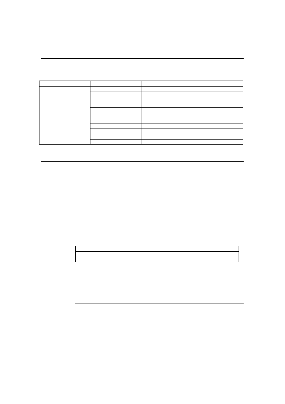
Supported Processors
The Olympus III motherboard supports the following 478-pin Intel® Pentium® 4
processors:
Processor Speed FSB Cache Size
Intel® Pentium® 4
processor
3.20 GHz 800 MHz 512 KB
3.00 GHz 800 MHz 512 KB
3.06 GHz 533 MHz 512 KB
2.80C GHz 800 MHz 512 KB
2.80 GHz 533 MHz 512 KB
2.66 GHz 533 MHz 512 KB
2.60C GHz 800 MHz 512 KB
2.53 GHz 533 MHz 512 KB
2.40C GHz 800 MHz 512 KB
2.40B GHz 533 MHz 512 KB
2.26 GHz 533 MHz 512 KB
Supported System Memory
The AMI Olympus III motherboard has four DIMM sockets and supports the following
memory features:
• 2.5 V 184-pin DDR SDRAM DIMMs
• Unbuffered, single-sided or double-sided DIMMs
• Double-sided DIMMs with 16 chips are not supported
• A maximum of 4 GB of total system memory
• A minimum of 64 MB of total system memory
• ECC and non-ECC DIMMs supported
• Serial Presence Detect (SPD)
• DDR400 and DDR333 SDRAM DIMMs
The following table lists the supported FSB and memory speed combinations.
To use: the FSB must be:
DDR400 800 MHz
DDR333 800 MHz or 533 MHz
Note: It is advisable to populate the Olympus III motherboard with DIMMs that support the
Serial Presence Detect (SPD) data structure. This allows the AMIBIOS to read the SPD
data and program the chipset to accurately configure memory settings for optimum
performance. If non-SPD memory is installed, the AMIBIOS will attempt to correctly
configure the memory settings, but performance and reliability may be impacted or the
DIMMs may not function under the determined frequency.
Cont’d
American Megatrends, Inc., Olympus III User’s Guide (Series 875)
6
Page 17

Supported System Memory, Continued
The following table is a list of SDRAM types that are supported per bank:
DIMM
Capacity
64 MB Single-Sided 64 Mbit 8 M x 8 empty 8
64 MB Single-Sided 128 Mbit 8 M x 16 empty 4
128 MB Double-Sided 64 Mbit 8 M x 8 8 M x 8 16
128 MB Single-Sided 128 Mbit 16 M x 8 empty 8
128 MB Single-Sided 256 Mbit 16 M x 16 empty 4
256 MB Double-Sided 128 Mbit 16 M x 8 16 M x 8 16
256 MB Single-Sided 256 Mbit 32 M x 8 empty 8
256 MB Single-Sided 512 Mbit 32 M x 16 empty 4
512 MB Double-Sided 256 Mbit 32 M x 8 32 M x 8 16
512 MB Single-Sided 512 Mbit 64 M x 8 empty 8
1024 MB Double-Sided 512 Mbit 64 M x 8 64 M x 8 16
Configuration DDR SDRAM
Density
DDR SDRAM
Organization
Front-side
DDR SDRAM
Organization
Back-side
Number of
DDR SDRAM
Devices
More Features
Faster, 128-bit dual channel DDR 400 memory support
• DDR 400 memory alone in single channel supports a maximum theoretical
bandwidth of 3.2 GB/s; while a dual channel supports 6.4 GB/s, the same
bandwidth speed that the 800 MHz FSB P4 can generate
• DDR 400 is implemented with Intel’s PAT for incredible performance from the
memory interface and provides exceptional performance across a full range of
multimedia and 3-D intensive applications
• Flexible memory technology allows a full spectrum of DDR usage from highest
performance to more cost-effective systems. ECC ensure data reliability and
800 MHz FSB CPU support (200 MHz quad-pumped)
• The key factor in enhancing system performance
• All of the 875P's predecessors and current competitors max out at 533 MHz,
• Supports platform longevity for the fastest Intel Pentium 4 processor
integrity.
which should give them a peak bandwidth of 4.2GB/s. The 875P's peak
theoretical bus bandwidth is 6.4GB/s.
frequencies and delivers greater system bandwidth.
Cont’d
Chapter One : Hardware Specifications and Supported Features 7
Page 18

More Features, Continued
Serial ATA (SATA) support
• A faster and relatively new way to connect the hard drive to the rest of the
computer
• Up to now, if you wanted SATA you needed to have a Promise, Highpoint or
Silicon Image SATA controller chip. Intel is the first of the chipset
manufacturers to have a SATA controller built into its South Bridge
• The SATA specification lists the maximum transfer rate as 15 0MB/s, which is
13 percent more bandwidth than a 32-bit/33 MHz PCI bus can provide!
• Intel brings the SATA controller onto the ICH and bypasses the PCI bus. The
SATA controller has a direct link to the Hub Link 2.0 interface in ICH5 and can
ICH
• The Intel I/O Controller Hub version 5 is the newest controller chip designed to
• ICH5 features two SATA channels (supporting a maximum of two drives) and
• Intel also gives another reason to say goodbye to third party SATA controllers
AGP 8X
• High-performance AGP 8X graphics interface for an advanced graphics
• Offers 2.1 GB/s of dedicated bandwidth
• Highest bandwidth graphics interface enables upgradability to the latest graphics
Integrated hi-speed USB 2.0
• Eight ports offer up to 40x greater bandwidth over USB 1.1 for a variety of
Enhanced AC '97 Audio
• Enhanced AC '97 audio implementation with dual independent DMA audio
• Delivers improved sound quality and new audio usage models and enables a
• Supports Dolby* Digital 5.1 surround sound(1), delivering six channels of
offer a full 150 MB/s per channel.
work with the I875P and I865 chipsets. There are two major features of ICH5
that separate it from its predecessor, ICH4; the first feature is integrated support
for a total of eight USB 2.0 ports.
two Parallel ATA channels (supporting a maximum of four drives), all of which
may be enabled and used concurrently.
with the inclusion of RAID function in the ICH5R version. This allows you to
use RAID 0 or 1 on the Serial ATA drives connected to the ICH5R.
experience
cards.
today's demanding high-speed I/O peripherals.
engines
user to make a PC phone call while playing digital music streams
enhanced sound quality.
Cont’d
American Megatrends, Inc., Olympus III User’s Guide (Series 875)
8
Page 19

More Features, Continued
Error Correction Code
Error Correction Code is supported for users that demand memory data reliability and
integrity
Hyper-Threading Technology
• Optimized to support the Pentium® 4 Processor with Hyper-Threading
Technology, the 875P chipset adds intelligence to help manage and prioritize
multiple threads received from the microprocessor.
• Delivers increased system responsiveness and performance.
478-pin Processor Package Compatibility
• Supports the highest performance Intel Pentium 4 processors plus, the flexibility
Intel Performance Acceleration Technology (PAT)
• Increases memory and system-level performance by optimizing internal data
• PAT speeds data flow between the processor and system memory to increase
Full-duplex Gigabit Ethernet
• Dedicated 266 MB/s link to a full-duplex Gigabit Ethernet connection
Communications Streaming Architecture (CSA)
• CSA, in conjunction with the new Intel® PRO/1000 CT Desktop Connection
• Gigabit Ethernet is slowly becoming the new standard for Ethernet. Most
Low-Power Sleep Mode
• Saves Energy
to support other 478-pin Intel processors.
paths.
performance. The 875P chipset also offers a dedicated networking bus based on
Intel's new Communications Streaming Architecture
gigabit Ethernet controller, doubles the networking bandwidth possible with
today's PCI bus based solutions.
motherboard companies are now integrating Gb/E controllers onto their
motherboards, which allows 1000 megabit along standard Cat5E Ethernet cable
-- s a great increase in bandwidth.
Chapter One : Hardware Specifications and Supported Features 9
Page 20

American Megatrends, Inc., Olympus III User’s Guide (Series 875)
10
Page 21
Chapter 2 Hardware Installation
Overview
This chapter covers the basic hardware installation of the Olympus III motherboard.
Motherboard Installation
Use the following steps to install the motherboard, memory, CPU, and connectors.
Step Action
1 Unpack the Motherboard (and check jumper settings)
2 Install Memory
3 Install CPU and Connect CPU Heatsink and Fan
4 Install the Motherboard (and I/O shield)
5 Attach Internal Cables
6 Installing Expansion Boards
7 Connect External Cables
8 Install Drivers
9 Test and Configure
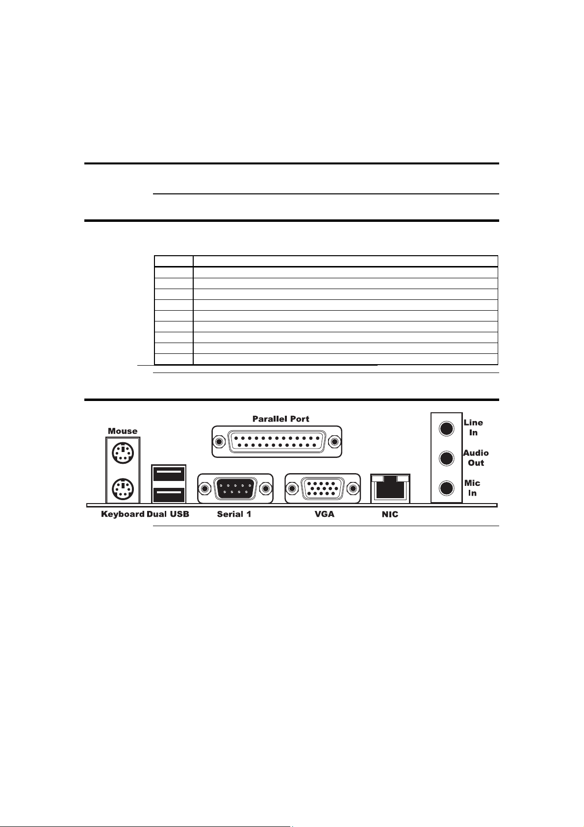
Rear I/O Ports
Chapter Two : Hardware Installation 11
Page 22
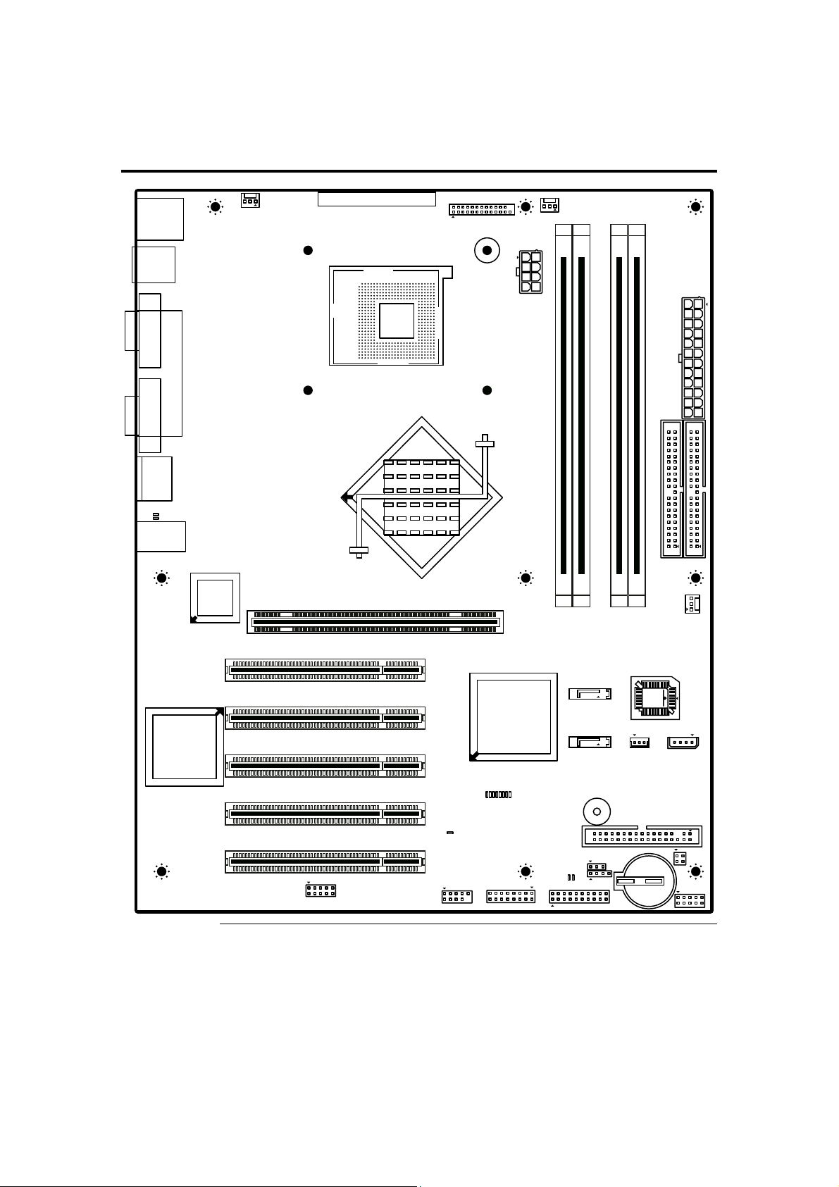
Motherboard Layout
JP5
JP7
SYSTEM FAN1
& MOUSE
PS2 KEYBOARD
SERIAL NUMBER
AMERICAN MEGATRENDS INC.
(C) 2003 SERIES 875 REV-A1
J1 ITP
CPU FAN
JP1
JP2
USB 0&1
COM 1
VGA
RJ45
MIC IN
SPR OUT
D3
D2
LINE IN
PARALLEL
PCI SLOT 1
SOCKET 478
AGP SLOT
8PIN POWER
J2 DDR A DIMM 0
J3 DDR A DIMM 1
J4 DDR B DIMM 0
J5 DDR B DIMM 1
J6 SECONDARY IDE
SYSTEM FAN2
24PIN POWER
J5 PRIMARY IDE
JP6
JP8
PCI SLOT 2
PCI SLOT 3
PCI SLOT 4
PCI SLOT 5
J20
American Megatrends, Inc., Olympus III User’s Guide (Series 875)
12
D17
USB 2&3
SATA 1
SATA 0
JP11 J17
D9
D10
D11
D12
D13
D14
D15
D16
J18
BUZZER
J13 FLOPPY
J10
D19
D18
J16
J19
BATTERY
J14
J21
Page 23

Step 1 Unpack the Motherboard
Step Action
1 Inspect the cardboard carton for obvious damage. If damaged, call 770-246-8600. Leave the motherboard in
its original packing.
2 Perform all unpacking and installation procedures on a ground-connected anti-static mat. Wear an anti-static
wristband grounded at the same point as the anti-static mat. Or use a sheet of conductive aluminum foil
grounded through a 1-megohm resistor instead of the anti-static mat. Similarly, a strip of conductive
aluminum foil wrapped around the wrist and grounded through a 1 megaohm resistor serves the same
purpose as the wristband.
3 Inside the carton, the motherboard is packed in an anti-static bag, and sandwiched between sheets of
packaging sponge. Remove the sponge and the anti-static bag. Place the motherboard on a grounded
anti-static surface component side up. Save the original packing material.
4 Inspect the motherboard for damage. Do not apply power to the motherboard if it has been damaged.
5 If the motherboard is undamaged, it is ready to be installed.
Avoid Electro-Static Discharge (ESD)
Electro-Static Discharge (ESD) will damage the motherboard and other system
components. Keep the motherboard in the anti-static bag until it is to be installed.
Wear an anti-static wrist-grounding strap before handling the motherboard. Make sure
you stand on an anti-static mat when handling the motherboard.
Avoid contact with any component or connector on any adapter card, printed circuit
board, or memory module. Handle these components by the mounting bracket.
Chapter Two : Hardware Installation 13
Page 24
Step 1 Unpack the Motherboard, Continued
Set Jumpers
Set all jumpers and install the CPU before placing the motherboard in the chassis.
JP10 Clear CMOS
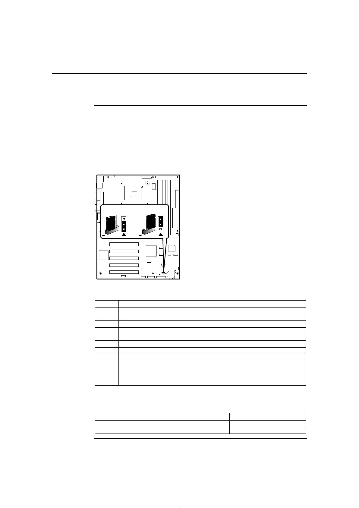
JP10 is a 3-pin berg that can be used to erase the contents of CMOS RAM, where all
system configuration information is stored.
Before you change JP10 from the default setting (1-2), turn off the power supply using
the mechanical switch (not the soft-off power button.) This switch is normally located on
the power supply. If there is no switch, remove the AC cord going to the power supplies.
Normal
3
2
1
Clear CMOS
3
2
1
JP10
To drain CMOS RAM power, perform the following steps:
Step Action
1 Turn off power to the computer.
2 Remove the computer cover.
3 Remove the jumper from pins 1-2 of JP10.
4 Place a shorting bridge on pins 2-3 of JP10.
5 Wait for five seconds.
6 Remove the shorting bridge from pins 2-3 of JP10.
7 Put the shorting bridge back on pins 1-2 of JP10.
8 Turn on computer power again.
Since you drained power from CMOS RAM, all system configuration information
has been erased. You must now re-enter the system configuration information by
running AMIBIOS Setup.
You must then reboot the computer, run AMIBIOS Setup, and restore all system
configuration information. The JP10 settings are:
CMOS Drain Jumper Setting
Normal operation (factory setting). 1-2
The contents of CMOS RAM are destroyed. 2-3
American Megatrends, Inc., Olympus III User’s Guide (Series 875)
14
Page 25

Step 2 Install Memory
Memory Overview
The AMI Olympus III motherboard has four DIMM sockets and supports the following
memory features:
• DIMM modules can be plugged into any slot (or combination of slots)
• 2.5 V 184-pin DDR SDRAM DIMMs
• Unbuffered, single-sided or double-sided DIMMs
• Double-sided DIMMs with 16 chips are not supported
• A maximum of 4 GB of total system memory
• A minimum of 64 MB of total system memory
• ECC and non-ECC DIMMs supported
• Serial Presence Detect (SPD)
• DDR400 and DDR333 SDRAM DIMMs
Channel A (CHA), DIMM 0
Channel A (CHA), DIMM 1
Channel B (CHB), DIMM 0
Channel B (CHB), DIMM 1
The following table lists the supported FSB and memory speed combinations.
To use: the FSB must be:
DDR400 800 MHz
DDR333 800 MHz or 533 MHz
Note: It is advisable to populate the Olympus III motherboard with DIMMs that support the
Serial Presence Detect (SPD) data structure. This allows the AMIBIOS to read the SPD
data and program the chipset to accurately configure memory settings for optimum
performance. If non-SPD memory is installed, the AMIBIOS will attempt to correctly
configure the memory settings, but performance and reliability may be impacted or the
DIMMs may not function under the determined frequency.
Cont’d
Chapter Two : Hardware Installation 15
Page 26

Step 2 Install Memory, Continued
Supported Memory
The following table is a list of SDRAM types that are supported per bank:
DIMM
Capacity
64 MB Single-Sided 64 Mbit 8 M x 8 empty 8
64 MB Single-Sided 128 Mbit 8 M x 16 empty 4
128 MB Double-Sided 64 Mbit 8 M x 8 8 M x 8 16
128 MB Single-Sided 128 Mbit 16 M x 8 empty 8
128 MB Single-Sided 256 Mbit 16 M x 16 empty 4
256 MB Double-Sided 128 Mbit 16 M x 8 16 M x 8 16
256 MB Single-Sided 256 Mbit 32 M x 8 empty 8
256 MB Single-Sided 512 Mbit 32 M x 16 empty 4
512 MB Double-Sided 256 Mbit 32 M x 8 32 M x 8 16
512 MB Single-Sided 512 Mbit 64 M x 8 empty 8
1024 MB Double-Sided 512 Mbit 64 M x 8 64 M x 8 16
Configuration DDR SDRAM
Density
DDR SDRAM
Organization
Front-side
DDR SDRAM
Organization
Back-side
Memory Configuration
The Olympus III motherboard has the following features for enhancing memory
throughput:
• Dual Channel memory interface. The Olympus III motherboard has two
memory channels (CHA and CHB), each with two DIMM sockets.
• Dynamic Addressing Mode. Dynamic mode minimizes overhead by reducing
memory accesses.
Characteristics of Dual and Single Channel Configuration with and without
Dynamic Mode:
Throughput
Level
Highest Dual Channel with Dynamic Mode All DIMMs matched
Higher
Lower
Lowest
Configuration Characteristics
Dual Channel without Dynamic
Mode
Single Channel with Dynamic Mode Single DIMM or DIMMs matched
Single Channel without Dynamic
Mode
• DIMMs matched from Channel
A to Channel B
• DIMMs not matched within
channels
within a channel
DIMMs not matched
Number of
DDR SDRAM
Devices
Cont’d
American Megatrends, Inc., Olympus III User’s Guide (Series 875)
16
Page 27
Step 2 Install Memory, Continued
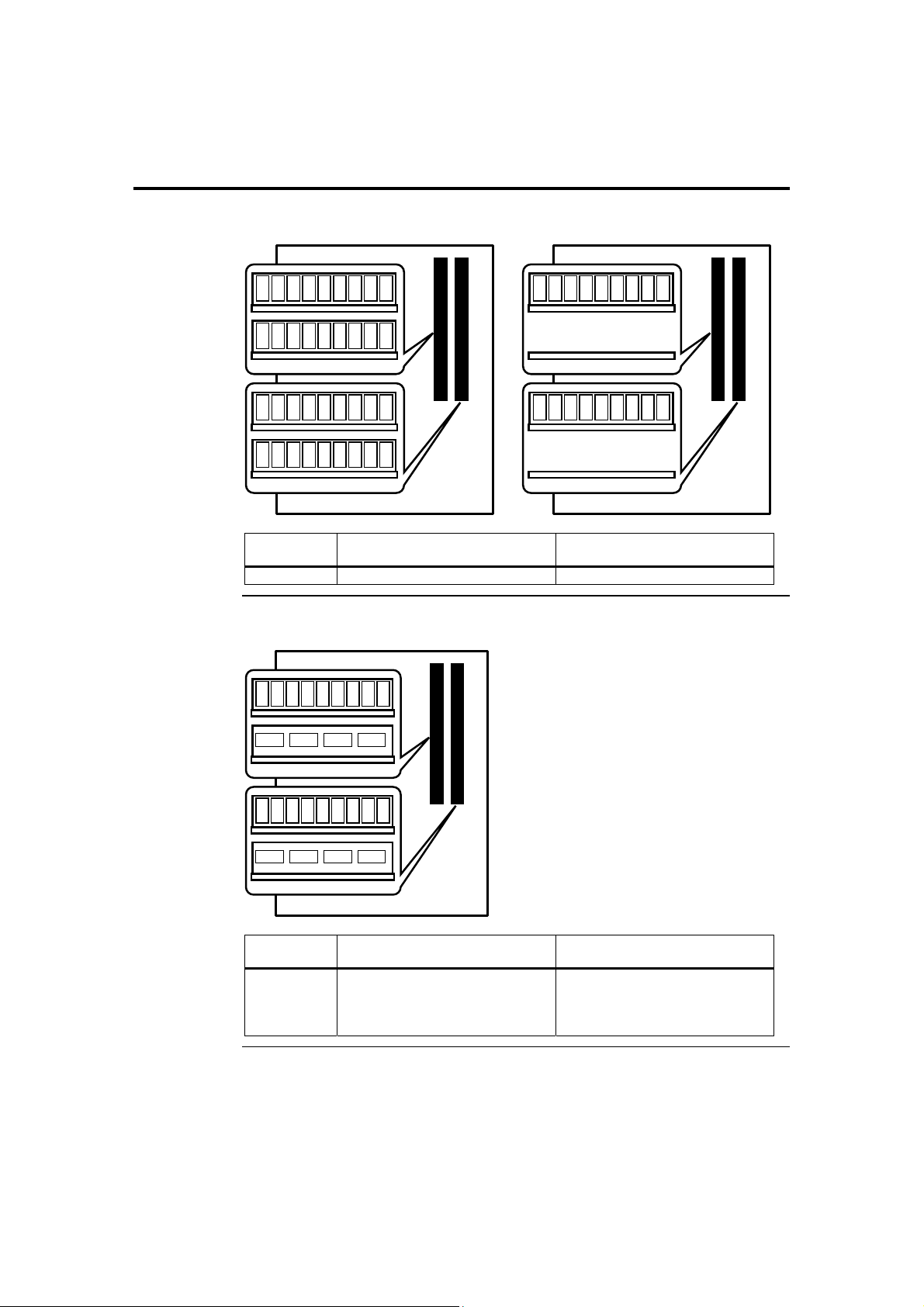
Highest Throughput Level (RECOMMENDED)
Channel A (CHA), DIMM 0
Channel A (CHA), DIMM 1
Channel B (CHB), DIMM 0
Channel B (CHB ), DIMM 1
Throughput
Level
Highest Dual Channel with Dynamic Mode All DIMMs matched
Configuration Characteristics
Second Highest Throughput Level
Channel A (CHA), DIMM 0
Channel A (CHA), DIMM 0
Channel A (CHA), DIMM 1
Channel B (CHB), DIMM 0
Channel B (CHB ), DIMM 1
Channel A (CHA), DIMM 1
Channel B (CHB), DIMM 0
Channel B (CHB ), DIMM 1
Throughput
Level
Higher
Configuration Characteristics
Dual Channel without Dynamic
Mode
• DIMMs matched from Channel
A to Channel B
• DIMMs not matched within
channels
Chapter Two : Hardware Installation 17
Cont’d
Page 28

Step 2 Install Memory, Continued
Second Lowest Throughput Level
Channel A (CHA), DIMM 0
Channel A (CHA), DIMM 1
Channel B (CHB), DIMM 0
Channel B (CHB ), DIMM 1
Throughput
Level
Lower Single Channel with Dynamic Mode Single DIMM or DIMMs matched
Lowest Throughput Level
Channel A (CHA), DIMM 0
Channel A (CHA), DIMM 0
Channel A (CHA), DIMM 1
Channel B (CHB), DIMM 0
Channel B (CHB ), DIMM 1
Configuration Characteristics
within a channel
Channel A (CHA), DIMM 0
Channel A (CHA), DIMM 1
Channel B (CHB), DIMM 0
Channel B (CHB ), DIMM 1
Throughput
Level
Lowest Single Channel without Dynamic
American Megatrends, Inc., Olympus III User’s Guide (Series 875)
18
Configuration Characteristics
Mode
Channel A (CHA), DIMM 1
Channel B (CHB), DIMM 0
Channel B (CHB ), DIMM 1
DIMMs not matched
Cont’d
Page 29
Step 2 Install Memory, Continued
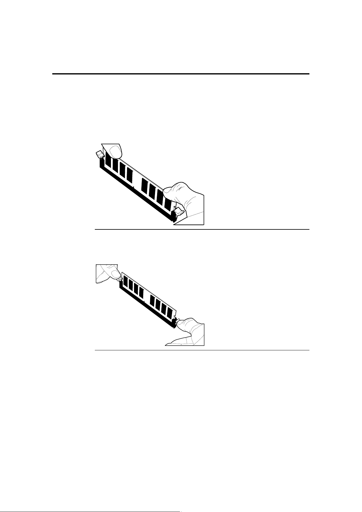
Inserting DIMM Modules
Locate the DIMM slot(s) you will be using. See the Memory Configuration section
located on the previous pages.
Match the DIMM module and DIMM slot so that the notches align properly. Insert the
module by sliding it straight down into the slot. Using your thumbs, press down on the
module until the tabs lock in place.
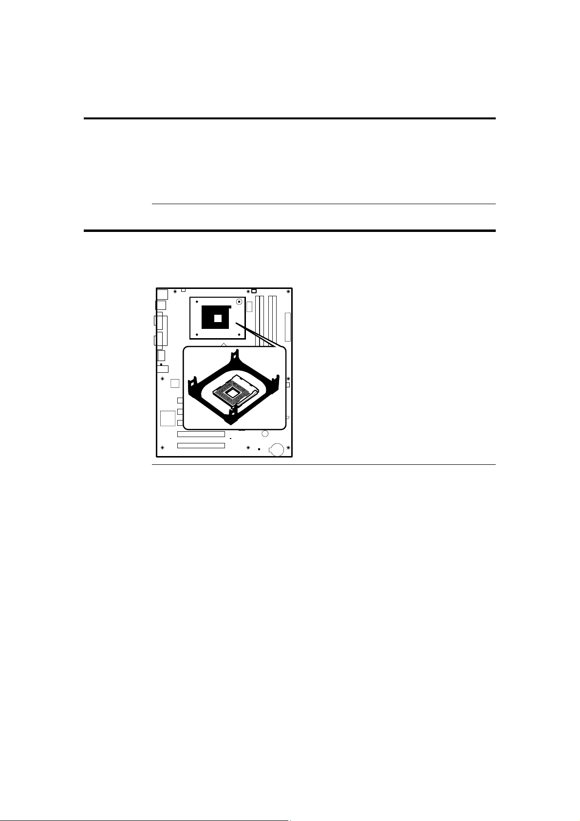
Removing DIMM Modules
To remove the module, press down on the tabs. This will eject the module.
Cont’d
Chapter Two : Hardware Installation 19
Page 30
Step 2 Install Memory, Continued
Memory Display
System memory is reported by AMIBIOS as it boots and again when the AMIBIOS
System Configuration Screen is displayed just before the operating system boots. The
memory displayed by AMIBIOS on the System Configuration Screen is 384 KB less than
the total memory installed.
Step 3 Install CPU and Connect Heatsink and Fan
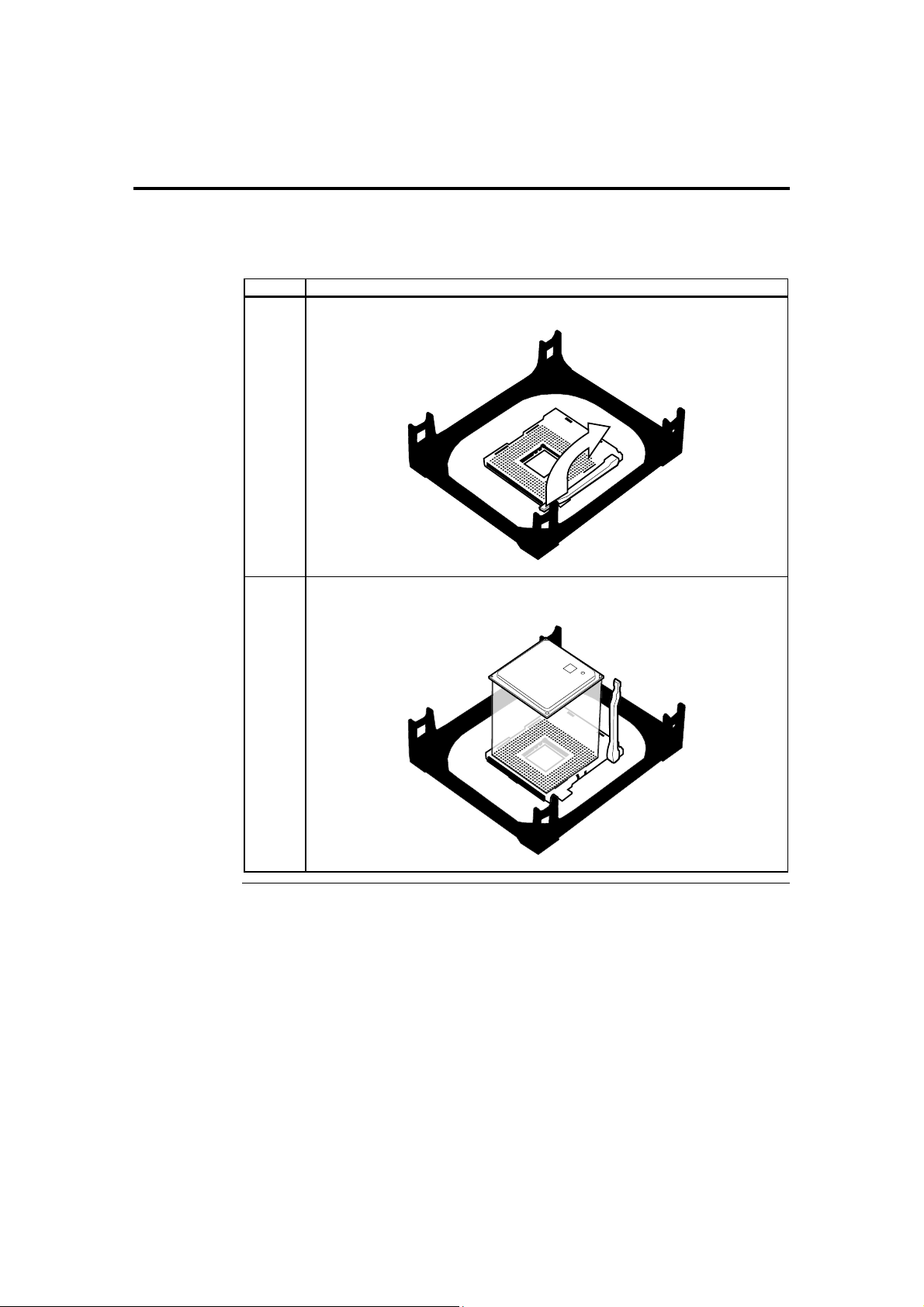
The Olympus III motherboard is equipped with a Socket 478 ZIF (zero insertion force)
socket. The CPU socket is located in the shaded are diagramed below along with its
CPU cooling fan connector location (JP2 CPU Fan header).
JP2
Cont’d
American Megatrends, Inc., Olympus III User’s Guide (Series 875)
20
Page 31
Step 3 Install CPU and Connect Heatsink and Fan, Continued
Note: The CPU heatsink/cooling fan installation described in this section is based on the
common retail packaged Intel® processor with heatsink/fan combination. For custom
OEM configurations, consult your CPU heatsink and cooling fan documentation.
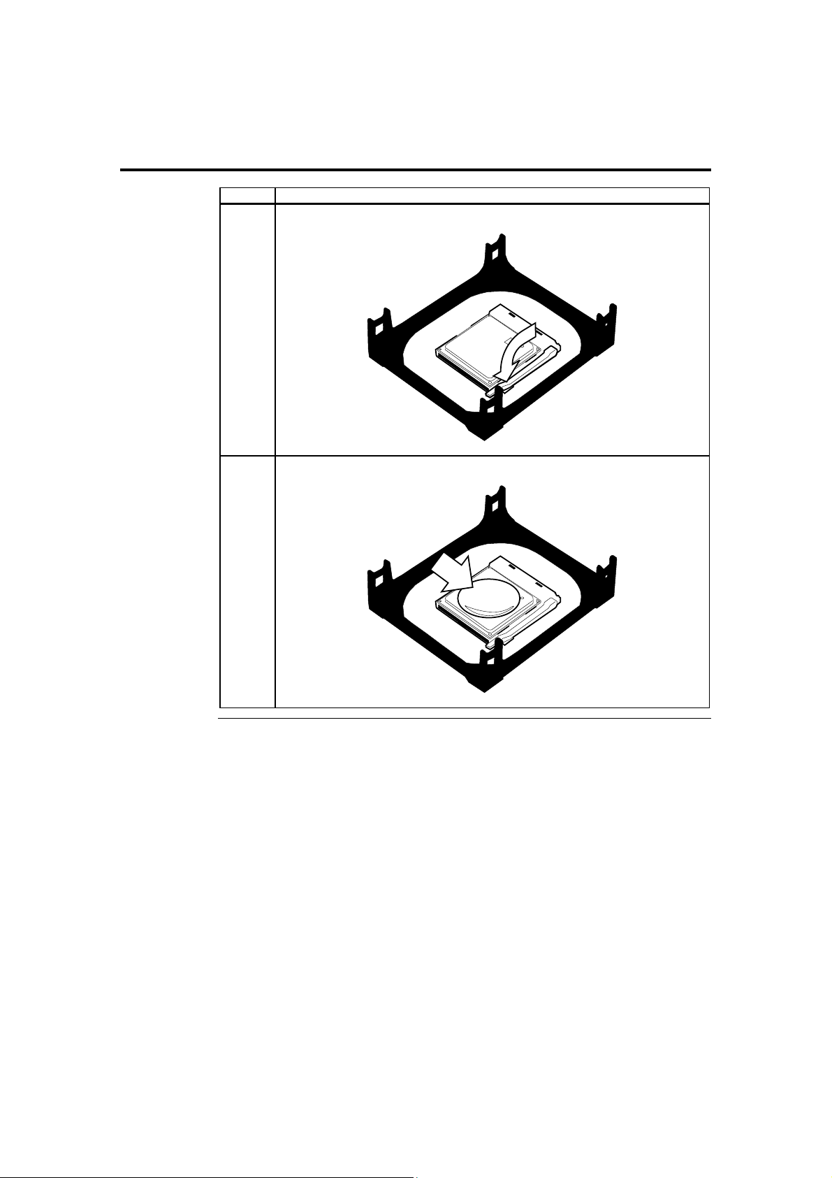
Step Action
1 Lift the lever on the ZIF socket.
2 Place the CPU into the ZIF socket. The CPU can only be inserted one way. It fits
snug and does not require force to be inserted.
Cont’d
Chapter Two : Hardware Installation 21
Page 32
Step 3 Install CPU and Connect Heatsink and Fan, Continued
Step Action
3 Once inserted, depress the lever to secure the CPU to the ZIF socket.
4 Apply silicon thermal gel to the top of your CPU.
Cont’d
American Megatrends, Inc., Olympus III User’s Guide (Series 875)
22
Page 33
Step 3 Install CPU and Connect Heatsink and Fan, Continued
Step Action
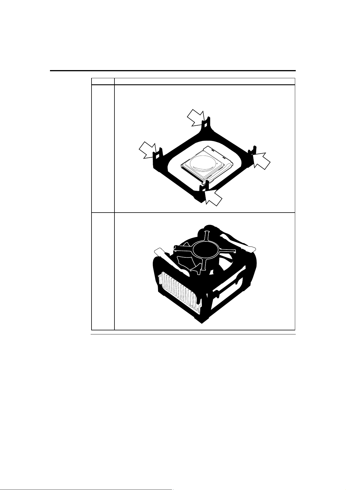
5 To install the heatsink and cooling fan, place the heat sink on top of the CPU and
clip it to the ZIF socket. Align the mounting bracket with the mounting clips of the
heatsink and cooling fan.
6 Secure the heatsink and cooling fan to the socket base.
Cont’d
Chapter Two : Hardware Installation 23
Page 34
Step 3 Install CPU and Connect Heatsink and Fan, Continued
Step Action
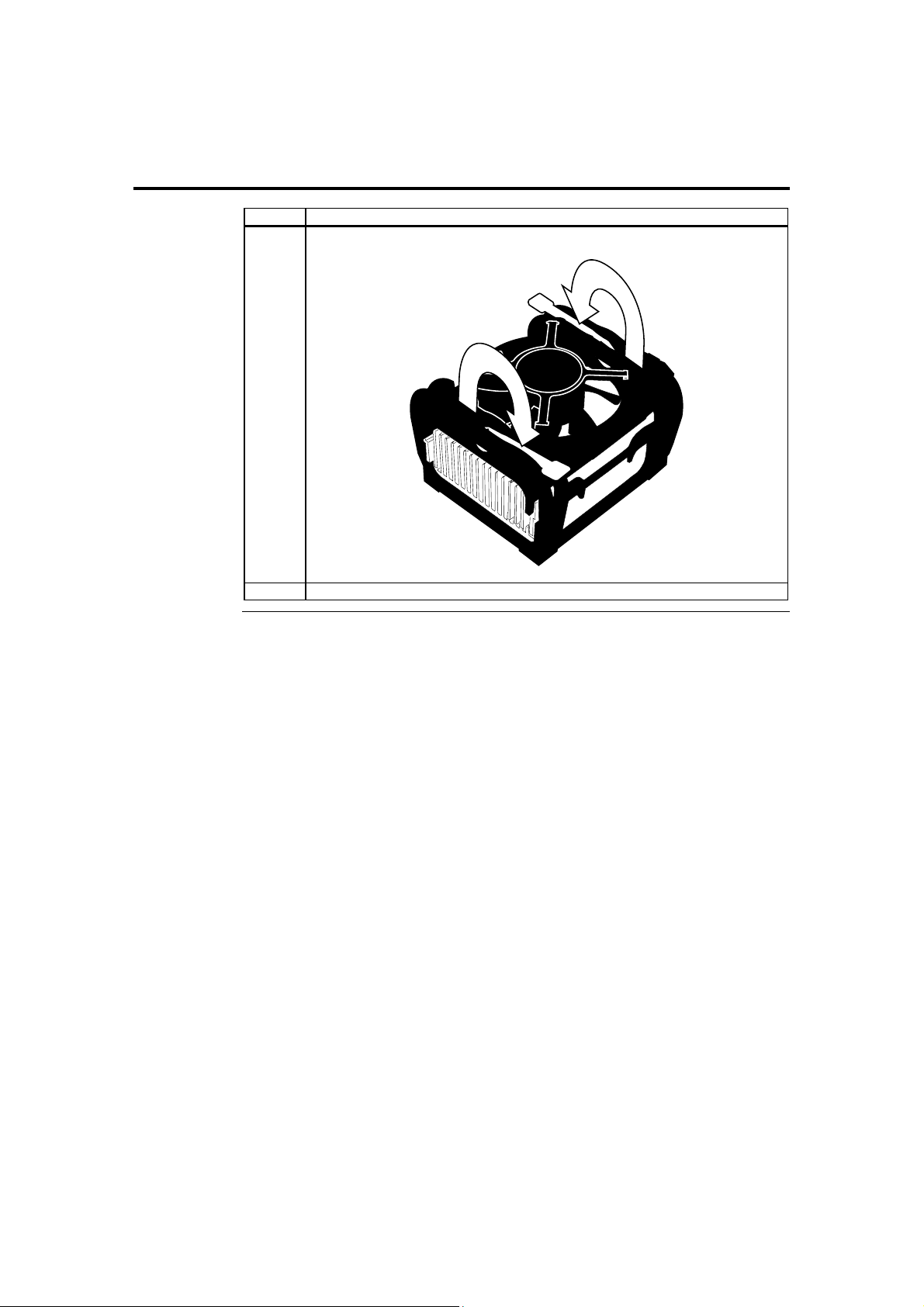
7 Flip the two levers to secure the heatsink and cooling fan to the socket base.
8 Connect the fan power cable to the adjacent JP2 CPU Fan header.
American Megatrends, Inc., Olympus III User’s Guide (Series 875)
24
Page 35
Step 4 Install the Motherboard
Note: We encourage integrators to choose a chassis that complies with the ATX 2.01 (or later)
specification.
Step Action
1
2 Rotate the chassis so the front is to the right, and the rear is to the left. The side facing you is where the
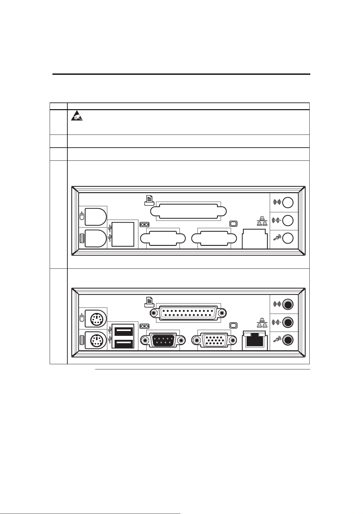
3 Hold the motherboard with the component-side facing up. The printer, serial, VGA, LAN, and dual USB
4 Remove the I/O shield that is currently installed in the chassis if applicable. Locate the I/O shield that came
Place the chassis on an anti-static mat. Connect the chassis to ground to avoid static damage during
installation. Connect an alligator clip with a wire lead to any unpainted part of the chassis. Ground the other
end of the lead at the same point as the mat and the wristband.
motherboard is mounted. The power supply is mounted at the far end of the chassis.
ports should be to the left.
with the Olympus III and remove the extra metal plates that cover the openings (if applicable). Locate the I/O
shield label and remove the protective backing. Attach it to the I/O shield.
Install the Olympus III I/O shield into the chassis.
5 Carefully slide the motherboard into the chassis. Make certain the edge connectors fit the I/O shield port
openings in the rear of the chassis. The motherboard should rest level with the chassis.
Cont’d
Chapter Two : Hardware Installation 25
Page 36
Step 4 Install the Motherboard, Continued
Step Action
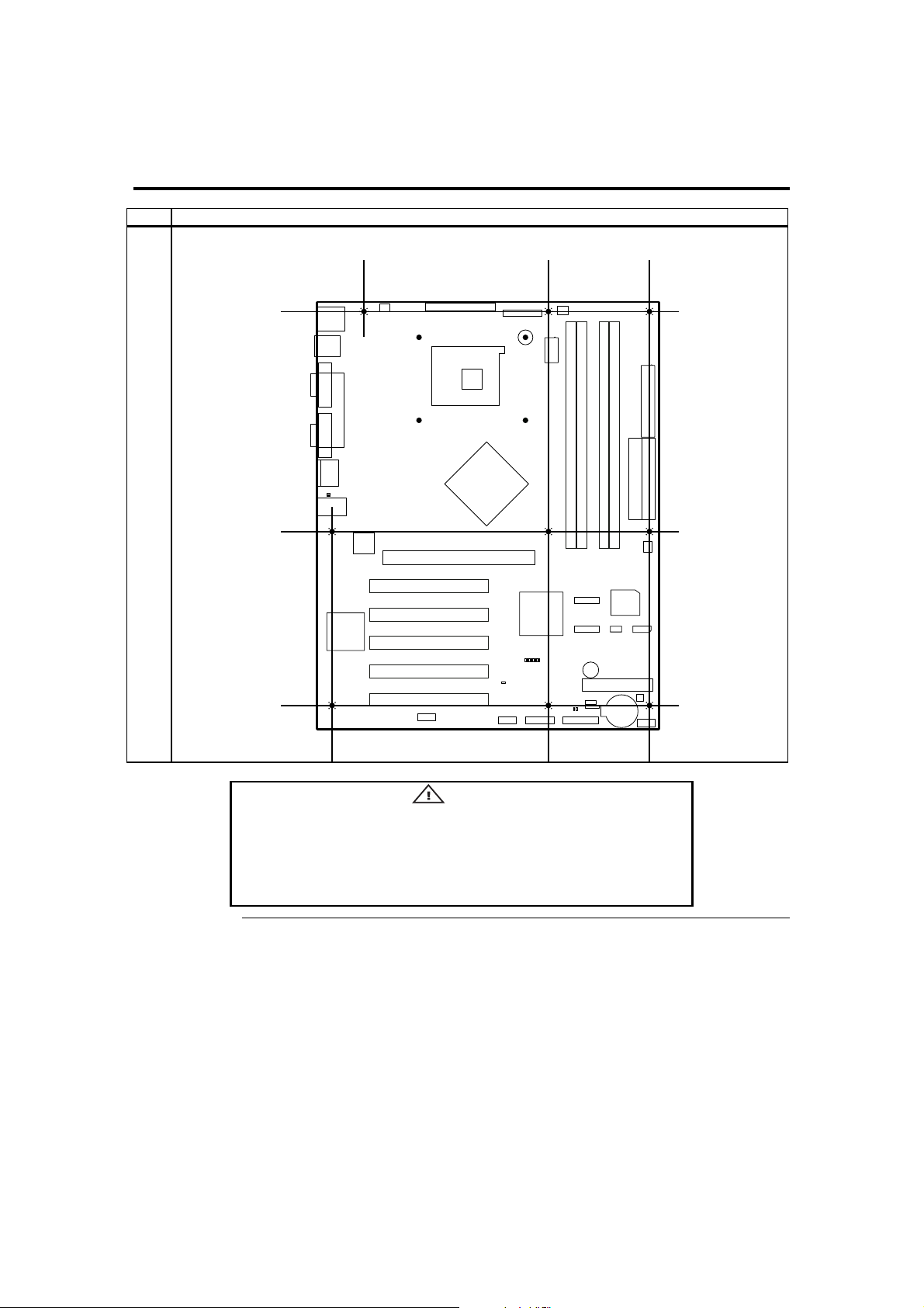
6 Place the mounting screws in the holes provided and tighten them. If necessary, shift the motherboard
slightly to align the mounting holes on the motherboard with the holes on the chassis.
If using metallic screws, make sure you use them only in the plated
mounting holes.
If using metallic screws, make sure the head of the screw fits completely
inside the plated mounting holes.
American Megatrends, Inc., Olympus III User’s Guide (Series 875)
26
Warning
Cont’d
Page 37

Step 5 Attach Internal Cables
Connectors
The Olympus III motherboard includes many connectors. Connection instructions,
illustrations of connectors, and pin-out locations are supplied in the following pages. A
list of all connectors described in this manual are as follows:
Location Connector Turn to page
CN1 8-pin ATX12V/SSI EPS12V Power Connector 28
CN2 24-pin Main Power Connector 28
CN4 Serial ATA 0 Connector 42
CN5 Serial ATA 1 Connector 42
JP2 CPU Cooling Fan Connector 48
JP5 Auxiliary Cooling Fan Connector 49
JP6 Auxiliary Cooling Fan Connector 49
JP10 Clear CMOS Jumper 14
JP11 Wake On LAN Connector 31
J1 ITP Connector 32
J6 Secondary IDE Connector 40
J7 Primary IDE Connector 40
J13 Floppy Drive Connector 39
J14 OEM BIOS Function Connector 33
J16 External Hard Disk Activity LED Connector 34
J17 IPMB Connector 35
J18 BMC Debug Connector 36
J19 Front Panel Connector 44
J20 External Serial Port Connector 37
J21 BMC Diagnostics & Recover Connector 38
Cont’d
Chapter Two : Hardware Installation 27
Page 38

Step 5 Attach Internal Cables, Continued
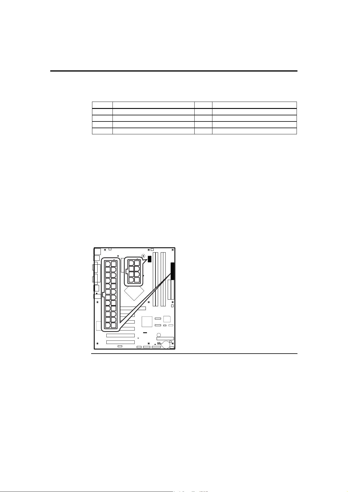
CN1 and CN2 ATX Power Supply Connectors
CN1
CN2
Attach the power cables from the power supply to the connectors located at CN1 and
CN2. The socket is keyed so that the ATX power supply connector can only mount one
way.
Note: Do not use a standard ATX power supply. The Olympus III motherboard will not boot
with a standard ATX power supply. Use only ATX12V-compliant or Server System
Infrastructure (SSI) Entry-Level Power Supply (EPS) EPS12V power supplies with the
Olympus III motherboard. ATX12V and EPS12V power supplies have an additional
power lead that provides required supplemental power for the Intel Pentium 4 processor.
The Olympus III motherboard will not boot if the ATX12V power supply is not
connected to both the CN1 4-pin (or 8-pin) and CN2 20-pin (or 24-pin) power
connectors.
For more information on ATX12V power supplies, see the formfactor.org website.
For more information on SSI EPS12V power supplies, see the ssiforum.org website.
The main power connector pinout is:
Pin Signal Name Pin Signal Name
1 3.3 V 13 3.3 V
2 3.3 V 14 -12 V
3 Ground 15 Ground
4 +5 V 16
5
6 +5 V 18 Ground
7 Ground 19 Ground
8
9 5 VSB 21 +5 V
10 +12 V 22 +5 V
11 +12 V 23 +5 V
12 +3.3 V 24 GND
Ground
Power OK
17 Ground
20 -5 V
Power Supply On
Cont’d
American Megatrends, Inc., Olympus III User’s Guide (Series 875)
28
Page 39
Step 5 Attach Internal Cables, Continued
CN1 and CN2 ATX Power Supply Connectors, Continued
The ATX12V/SSI EPS12V power connector pinout is:
Pin Signal Name Pin Signal Name
1 Ground 5 +12 V
2 Ground 6 +12 V
3 Ground 7 +12 V
4 Ground 8 +12 V
The power supply should match the physical configuration of the chassis. Make sure the
power switch is Off before assembly.
Before attaching all components, make sure the proper voltage has been selected. Power
supplies often can run on a wide range of voltages and must be set (usually via a switch)
to the proper range. Use at least a 300-watt ATX power supply, which should have builtin filters to suppress radiated emissions. Power supply voltage depends upon system load.
For example, +12V rating should be matched to the amount of the external load.
Attach the cables from the power supply to the power connector(s) on the motherboard.
ATX-compatible power supplies can have either one or two 20-pin (or 24-pin)
connectors. You can use either one or both power connectors.
For 24-pin /8-pin SSI EPS12V power supplies, plug the connectors into CN1 and CN2 as
illustrated in the following diagram:
CN1
CN2
Cont’d
Chapter Two : Hardware Installation 29
Page 40
Step 5 Attach Internal Cables, Continued
CN1 and CN2 ATX Power Supply Connectors, Continued
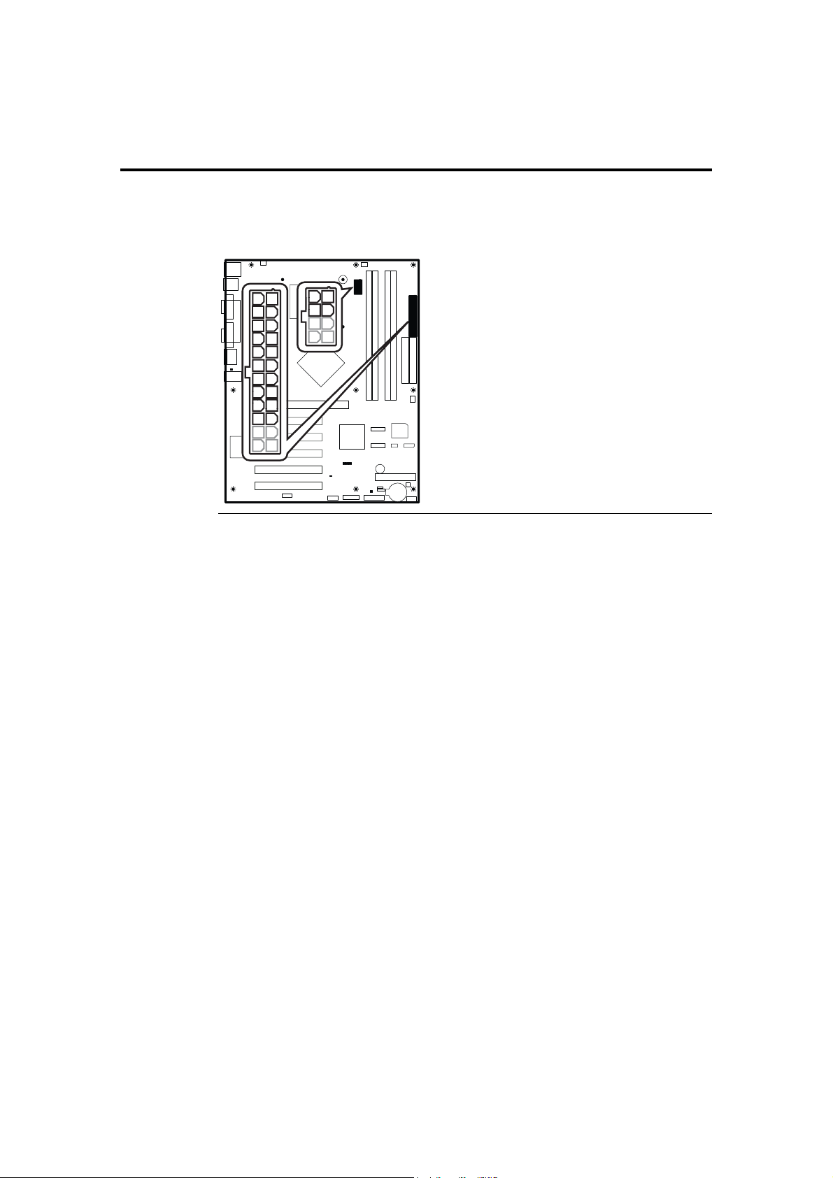
For 20-pin /4-pin ATX12V power supplies, plug the connectors into pin one first as
illustrated in the following diagram:
CN1
CN2
Cont’d
American Megatrends, Inc., Olympus III User’s Guide (Series 875)
30
Page 41
Step 5 Attach Internal Cables, Continued
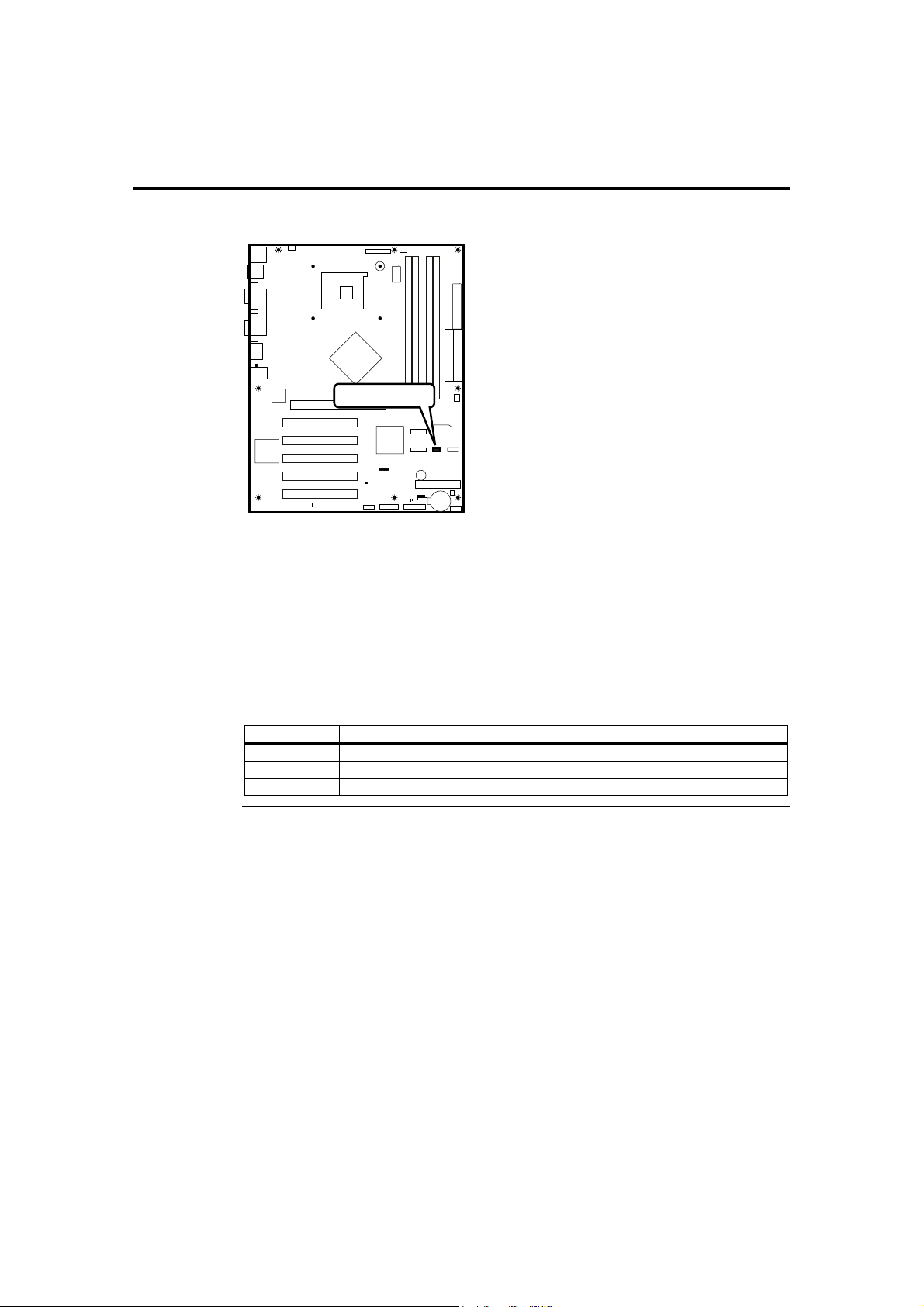
JP11 Wake On LAN connector
Wake On LAN
JP11
This connector is used to connect to a network adapter card that supports Wake-On-LAN
(WOL). WOL is the industry standard term used to describe the technology used to
remotely wake a computer system. A network adapter card that supports WOL has a
very-low-power mode to monitor the network for a special data packet that can wake up
the machine from standby mode (commonly known as S3) or hibernate mode (commonly
known as S4).
Connect your WOL cable from your network adapter card to this connector only if you
want to remotely wake up your computer system using a WOL compliant network
adapter.
Pin Signal Name
1 +3.3 V stand by
2 Ground
3 Wake on LAN signal
Cont’d
Chapter Two : Hardware Installation 31
Page 42
Step 5 Attach Internal Cables, Continued
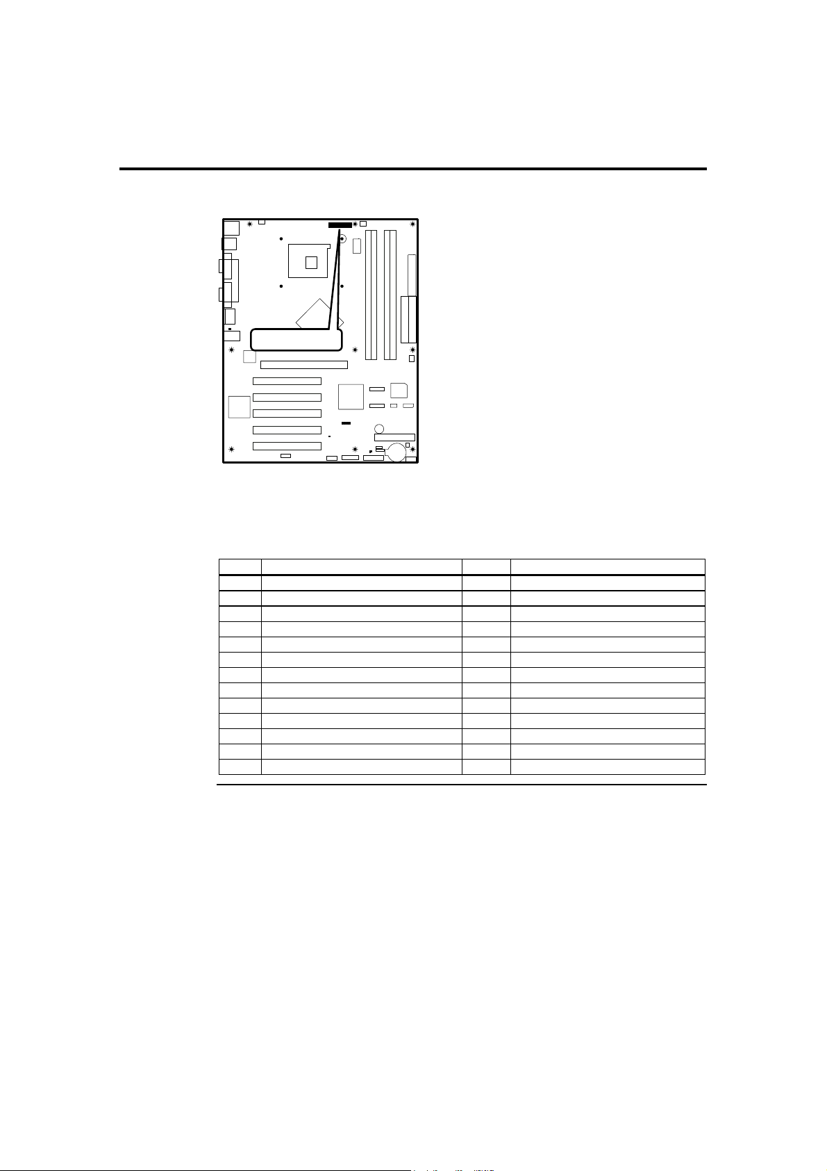
J1 ITP Connector
J1
ITP Connector
This is an In-Target Probe (ITP) connector. The physical connector may or may not be
mounted on your particular motherboard. This connector is not described in this manual.
This connector is used strictly for debugging OEM custom configurations. Contact your
American Megatrends OEM sales representative for custom OEM design services.
Pin Signal Name Pin Signal Name
1 Ground 2 Ground
3 H_BPM2-L 4 Not connected
5 H_BPM3-L 6 H_RST_DBR-L
7 H_BPM2-L 8 Ground
9 H_BPM3-L 10 H_TDI
11 H_BPM4-L 12 H_TMS
13 H_BPM5-L 14 H_TRST-L
15 H_CPURST-L 16 H_TCK
17 H_TCK_FB 18 Not connected
19 ITP_100M_T 20 Ground
21 ITP_100M_C 22 Pull up VCCP 1.5K
23 H_BPM5-L 24 H_TDO
25 Ground 26 Not connected
Cont’d
American Megatrends, Inc., Olympus III User’s Guide (Series 875)
32
Page 43
Step 5 Attach Internal Cables, Continued
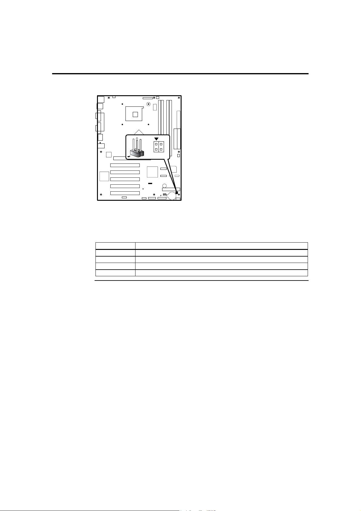
J14 OEM BIOS Function
3
214
J14
This is a custom four-pin BIOS driven connector. The physical connector may or may
not be mounted on your particular motherboard. This connector is not described in this
manual. This connector is used strictly for OEM custom configurations. Contact your
American Megatrends OEM sales representative for custom OEM design services.
Pin Signal Name
1 Must be defined by the OEM. This is a custom OEM design feature.
2 Must be defined by the OEM. This is a custom OEM design feature.
3 Ground
4 Ground
Cont’d
Chapter Two : Hardware Installation 33
Page 44

Step 5 Attach Internal Cables, Continued
J16 External Hard Disk Activity LED Connector
Hard Disk LED
J16
J16 External Hard Disk Activity LED connector is a 2 x 4-pin connector that allows an
expansion card hard disk drive controller to use the same LED as the onboard IDE
controller. For proper operation, this connector should be wired to the LED output of the
expansion card hard disk drive controller. The LED indicates when data is being read
from, or written to, either the expansion card hard disk drive controller or the onboard
IDE controller (Parallel ATA or Serial ATA).
Pin Signal Name
1 Hard Disk Activity
2 NC
3 NC
4 Hard Disk Activity
Cont’d
American Megatrends, Inc., Olympus III User’s Guide (Series 875)
34
Page 45
Step 5 Attach Internal Cables, Continued
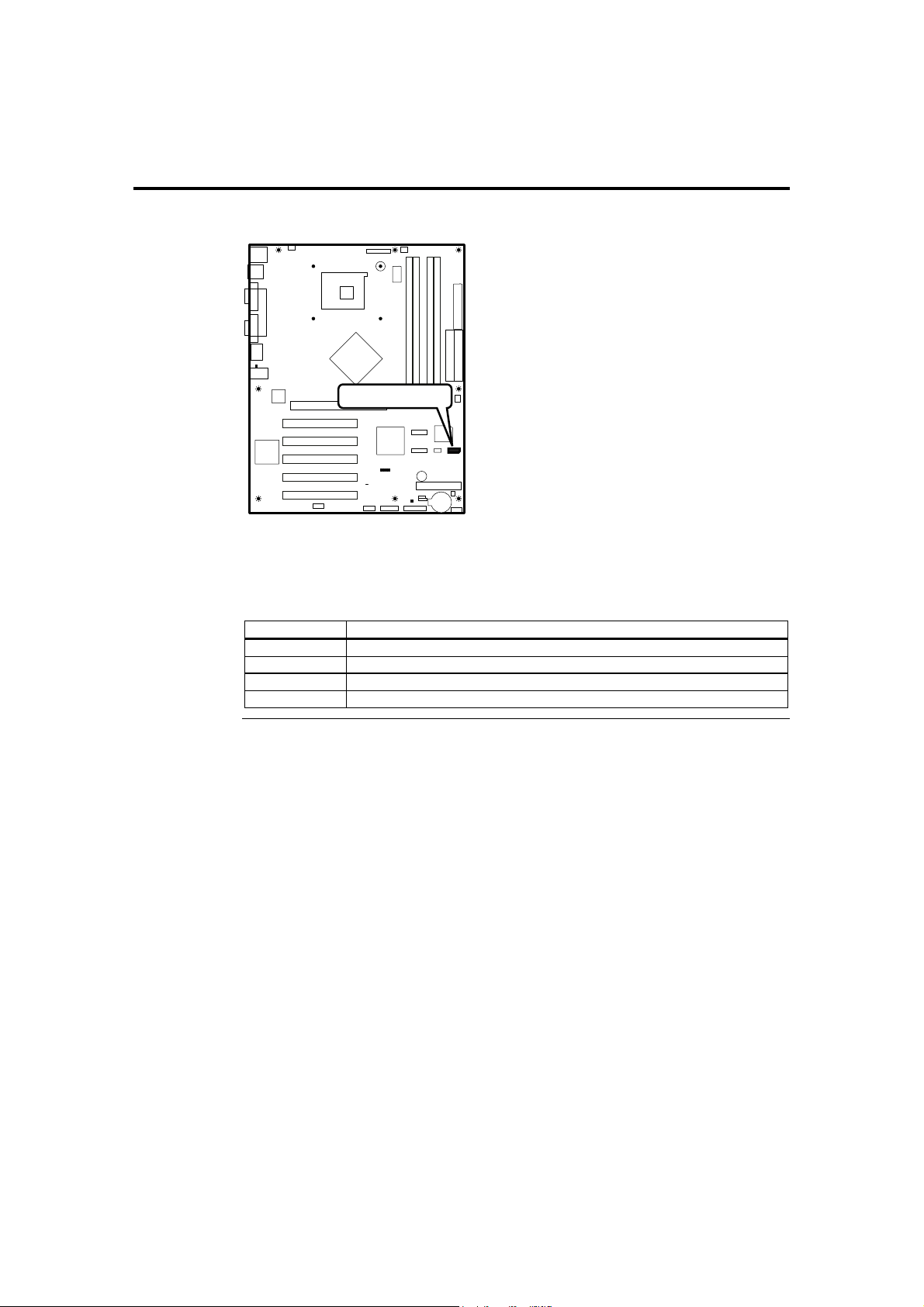
J17 IPMB Connector
IPMB Connector
J17
This connector can be used to externally monitor FRUs (Field Replaceable Units, such as
cooling fans, power supplies, and so on) on the Olympus III motherboard through a
management card, such as the MegaRAC remote management card. Attach the IPMB
connector from the MegaRAC card into J17 (if applicable).
Pin Signal Name
1 IPMB_SDA3
2 GND
3 IPMB_SCL3
4 NC
Cont’d
Chapter Two : Hardware Installation 35
Page 46
Step 5 Attach Internal Cables, Continued
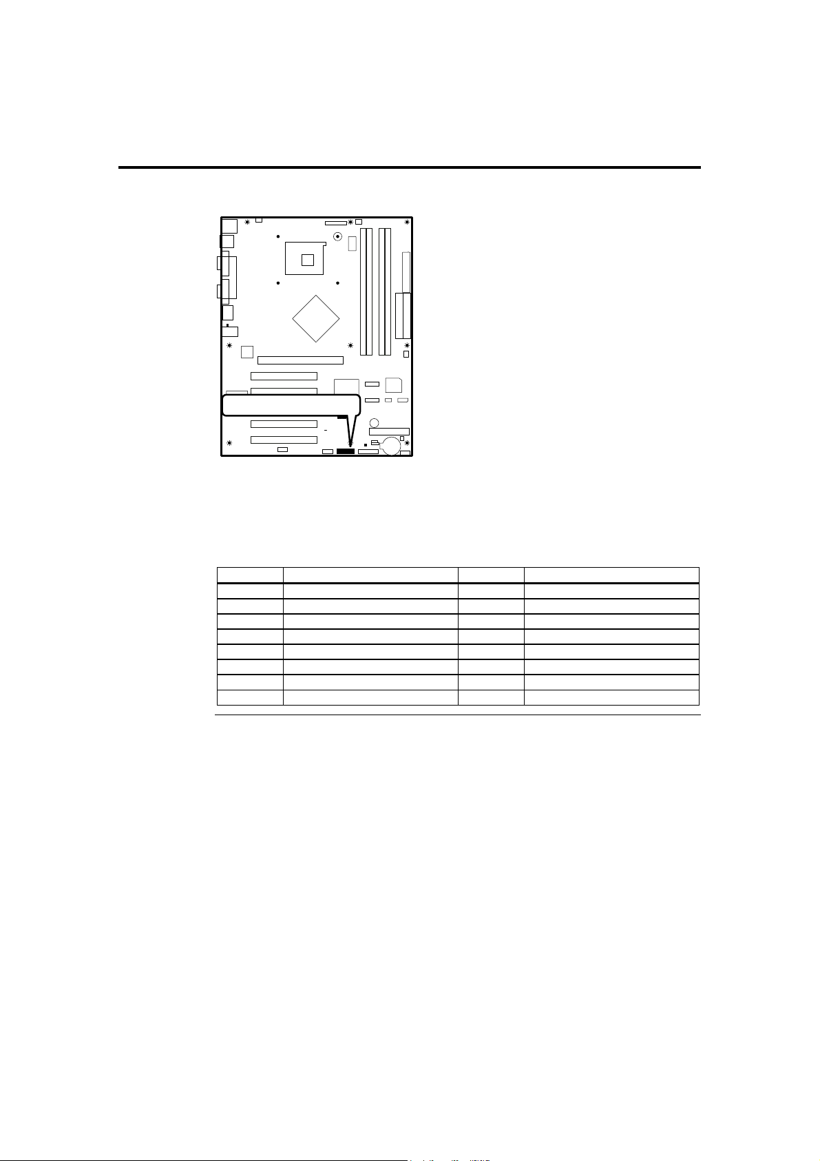
J18 BMC Debug Connector
BMC Debug Connector
J18
This is the BMC Debug connector used to debug the Hitachi® BMC chip. The physical
connector and Hitachi® BMC chip may or may not be mounted on your particular
motherboard. This connector and BMC chip is not described in this manual. This
connector is used strictly for debugging OEM custom configurations. Contact your
American Megatrends OEM sales representative for custom OEM design services.
Pin Signal Name Pin Signal Name
1 ETCK 2 GND
3 ETRST# 4 GND
5 ETDO 6 GND
7 RST_BMC 8 +3.3 V Stand by
9 ETMS 10 GND
11 ETDI 12 GND
13 Connected to Pin 7 14 GND
15 NC 16 NC
Cont’d
American Megatrends, Inc., Olympus III User’s Guide (Series 875)
36
Page 47
Step 5 Attach Internal Cables, Continued
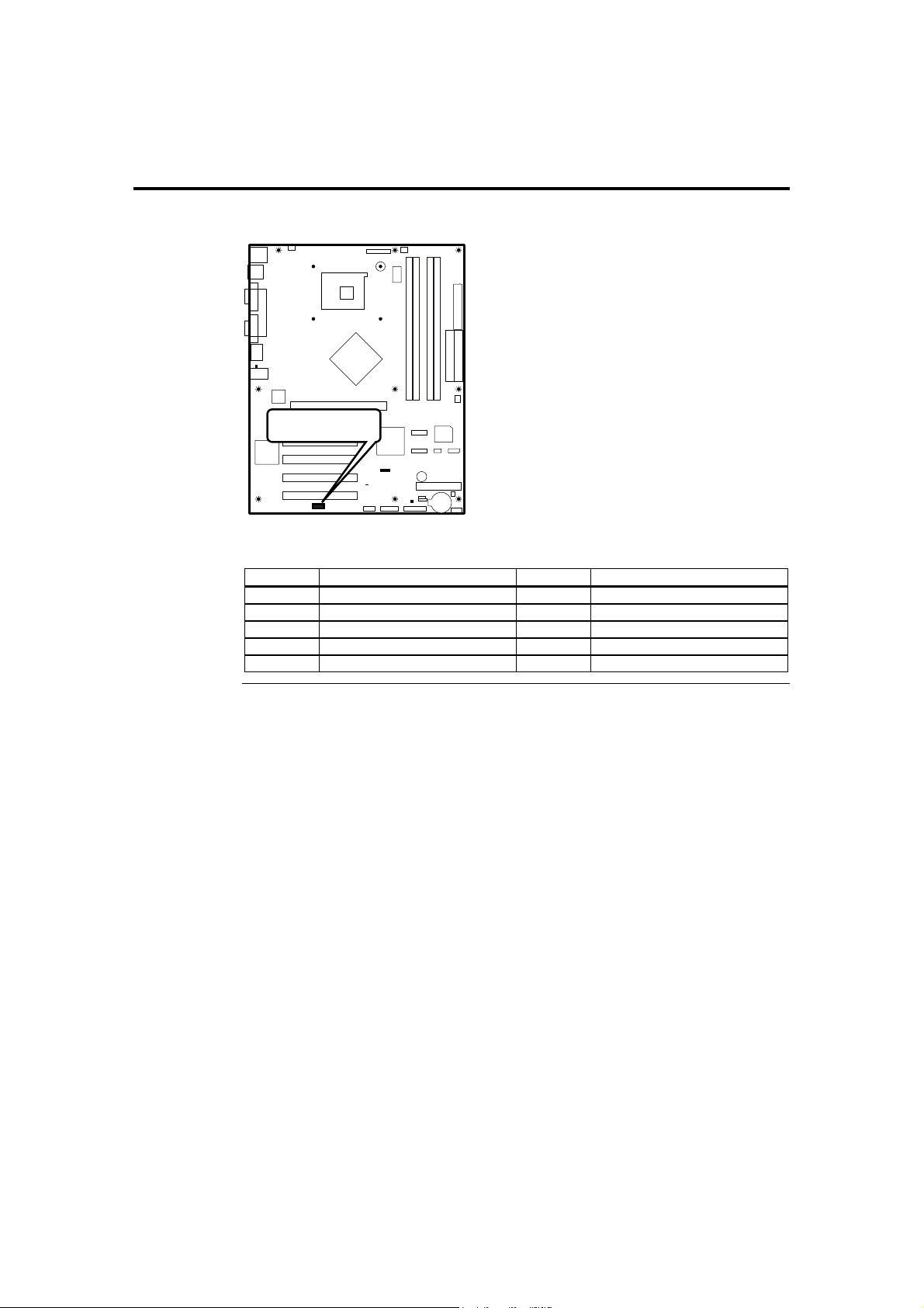
J20 External Serial Port Connector
External Serial
Port Connector
J20
Attach the external nine-pin serial cable with a D-type connector to jumper J20.
Pin Signal Name Pin Signal Name
1 DSRB 2 DCDB
3 RTSB 4 RXDB
5 CTSB 6 TXDB
7 RIB 8 DTRB
9 NC 10 GND(Connect L28,C479)
Cont’d
Chapter Two : Hardware Installation 37
Page 48
Step 5 Attach Internal Cables, Continued
J21 BMC Diagnostics and Recover Connector
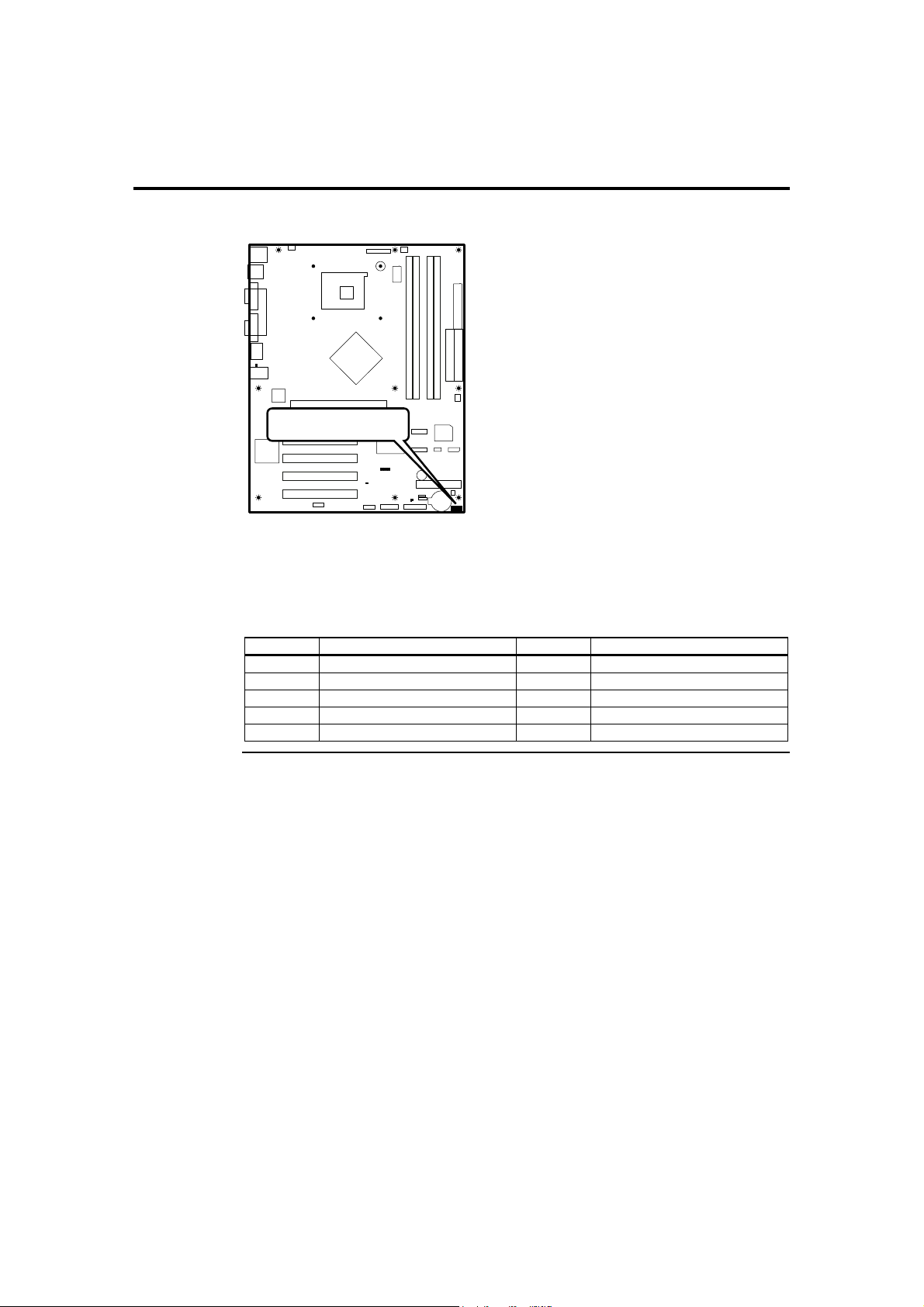
BMC Diagnostics &
Recover Connector
J21
This connector is used in conjunction with the Hitachi® BMC chip. The physical
connector and Hitachi® BMC chip may or may not be mounted on your particular
motherboard. This connector and BMC chip is not described in this manual. This
connector is used strictly for OEM custom configurations. Contact your American
Megatrends OEM sales representative for custom OEM design services.
Pin Signal Name Pin Signal Name
1 MD0 2 GND
3 MD1 4 GND
5 MD2 6 GND
7 BMC Diag 8 GND
9 BMC Recovery 10 GND
Cont’d
American Megatrends, Inc., Olympus III User’s Guide (Series 875)
38
Page 49
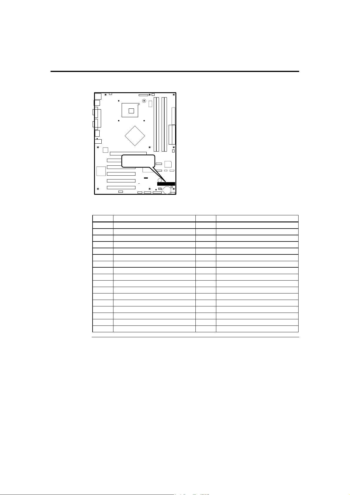
Step 5 Attach Internal Cables, Continued
J13 Floppy Drive Connector
Floppy Drive
Connector
J13
Attach your floppy disk drive to this connector.
Pin Signal Name Pin Signal Name
1 Ground 2 DENSEL
3 Ground 4 Reserved
5 Key 6 FDEDIN
7 Ground 8 FDINDX# (Index)
9 Ground 10 FDM00# (Motor Enabled A)
11 Ground 12 No Connect
13 Ground 14 FDDS0# (Drive Select A)
15 Ground 16 No Connect
17 No Connect 18 FDDIR# (Stepper Motor Direction)
19 Ground 20 FDSTEP# (Step Pulse)
21 Ground 22 FDWD# (Write Data)
23 Ground 24 FDWE# (Write Enable)
25 Ground 26 FDTRK0# (Track 0)
27 No Connect 28 FDWPD# (Write Protect)
29 Ground 30 FDRDATA# (Read Data)
31 Ground 32 FDHEAD# (Side 1 Select)
33 Ground 34 DSKCHG# (Diskette Change)
Cont’d
Chapter Two : Hardware Installation 39
Page 50
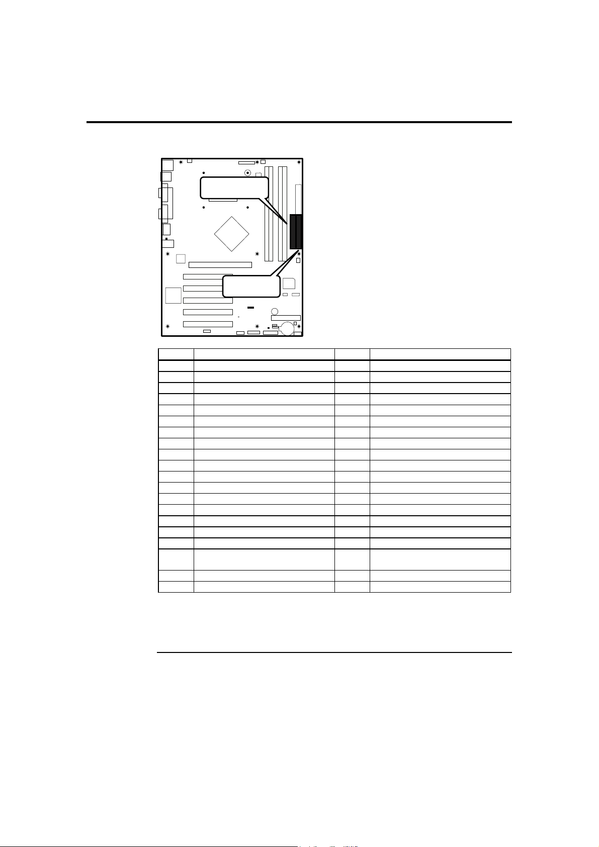
Step 5 Attach Internal Cables, Continued
J6 and J7 IDE Connectors
Secondary IDE
Connector
J6
Primary IDE
Connector
J7
Pin Signal Name Pin Signal Name
1 Reset IDE 2 Ground
3 Data 7 4 Data 8
5 Data 6 6 Data 9
7 Data 5 8 Data 10
9 Data 4 10 Data 11
11 Data 3 12 Data 12
13 Data 2 14 Data 13
15 Data 1 16 Data 14
17 Data 0 18 Data 15
19 Ground 20 Key
21 DDRQ0 22 Ground
23 I/O Write# 24 Ground
25 I/O Read# 26 Ground
27 IOCHRDY 28 P ALE (Cable Select Pull-up)
29 DDACK0# 30 Ground
31 IRQ 14 32 Reserved
33 DAG1 (Address 1) 34 ATA 6 Detect
35 DAG0
(Address 0)
37 Chip Select 1P# 38 Chip Select 3P#
39 Activity# 40 Ground
36 DAG2
(Address 2)
J7 is the primary IDE (Integrated Drive Electronics) hard disk drive connector. Both the
primary master and the primary slave IDE drives must be connected by cable to J7.
J6 is the secondary IDE hard disk connector.
Cont’d
American Megatrends, Inc., Olympus III User’s Guide (Series 875)
40
Page 51

Step 5 Attach Internal Cables, Continued
J7 is a 40-pin dual-inline berg that connects an IDE drive to the primary onboard IDE
connector. This motherboard supports the following:
Data Transfer Rate
(max.)
DMA Mode 1 11.1 MBs 40-pin IDE 40-pin no
Multi-word DMA
Mode 1
Multi-word DMA
Mode 2
Ultra ATA Mode 2
ATA-33
Ultra ATA Mode 4
ATA-66
Ultra ATA Mode 4
ATA-100
Ultra ATA Mode 4
ATA-133
13.3 MBs 40-pin IDE 40-pin no
16.6 MBs 40-pin IDE 40-pin no
33.3 MBs 40-pin IDE 40-pin yes
66.6 MBs 40-pin IDE 80-pin yes
99.9 MBs 40-pin IDE 80-pin yes
133.3 MBs 40-pin IDE 80-pin yes
These IDE features can be configured in the AMIBIOS Setup utility from the IDE
Configurations submenu in the Advanced section.
The IDE cable that is included with the Olympus III motherboard is a color-coded, 80
conductor/40 pin, ATA-100/133 IDE cable. Connect the blue connector to J7 and the
black connector to the primary master IDE device. The white connector is reserved for
the primary slave IDE device.
Ultra ATA-100/133
The Olympus III motherboard supports Ultra DMA-100/133. In order to take advantage
of this feature, you must have the following:
• DMA-aware operating system
• Ultra ATA-100/133 compatible IDE device
• 40-pin 80-conductor cable (included)
Note: Some IDE devices that are ATA-33 (and lower) cannot be used with the Ultra ATA-
100/133 cable. This is very rare. If the device is not recognized, you must use a standard
IDE cable. The Olympus III motherboard does not include a standard IDE cable.
Cable Conductors CRC
Cont’d
Chapter Two : Hardware Installation 41
Page 52

Step 5 Attach Internal Cables, Continued
CN4 and CN5 Serial ATA Connectors
Serial ATA 1
Connector
CN5
CN4
Serial ATA 0
Connector
The Olympus III motherboard has two independent Serial ATA ports. Serial ATA has a
theoretical maximum transfer rate of 150 MBs per Serial ATA port. One Serial ATA
device can be installed on each Serial ATA port for a maximum of two Serial ATA
devices.
For compatibility, the underlying Serial ATA functionality is transparent to the operating
system. The Serial ATA controller can operate in both legacy and native Serial ATA
modes. In legacy mode, standard resources are assigned, such as IRQ 14 and IRQ 15. In
Native Serial ATA mode, standard PCI resource steering is used. Native Serial ATA
mode is recommended for use with the Microsoft® Windows XP and Microsoft®
Windows 2000/2003 operating systems.
Pin Signal Name
1 Ground
2 TXP
3 TXN
4 Ground
5 RXN
6 RXP
7 Ground
Note: Serial ATA hard disk drives use new low-voltage power connectors and require adapters
or power supplies equipped with low-voltage power connectors. See serialata.org
for more information.
Cont’d
American Megatrends, Inc., Olympus III User’s Guide (Series 875)
42
Page 53

Step 5 Attach Internal Cables, Continued
Serial ATA RAID
The Olympus III motherboard supports RAID level 0 (disk striping) on the onboard
Serial ATA ports. Two physical hard disk drives, of identical size, can be teamed
together to create one logical drive. As data is written or retrieved from the logical drive,
both drives operate in parallel, thus increasing the throughput.
Note: The Olympus III motherboard provides support for RAID level 0 and RAID boot in
Microsoft® Windows XP only.
RAID Boot
A RAID array can be created by using the existing Serial ATA ports, correctly
configuring the BIOS, and installing drivers. The following steps are required to
successfully establish a RAID configuration.
Step Description
1 Enable RAID Support in BIOS
2 Create a RAID array using the Intel® Application Accelerator (IAA) utility
3 Install the IAA 3.0 RAID driver
4 Format the RAID array
Cont’d
Chapter Two : Hardware Installation 43
Page 54
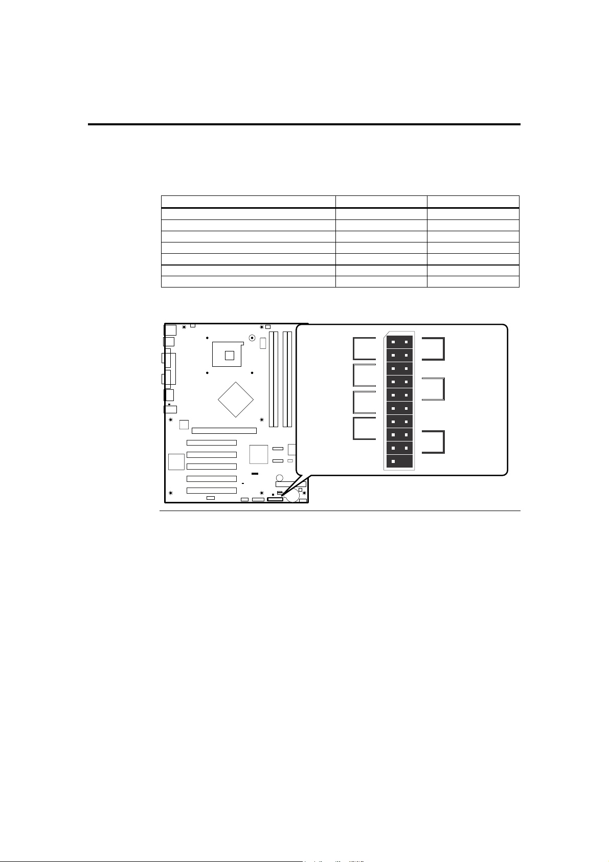
Step 5 Attach Internal Cables, Continued
J19 Front Panel Connector
The JP19 Front Panel Connector provides front panel chassis connections for the
following connectors:
Connector Pins Turn to
ATX Power Supply Soft ON/OFF 1 and 3
Reset Button 2 and 4
Parallel ATA Activity LED 5 and 7
Intrusion Sensor 8 and 10
Power LED 9 and 11
System Fault LED 13 and 15
Serial ATA Activity LED 16 and 18
The following is a diagram of the J19 header:
Power
Button
HDD Activity
LED
Power LED
System Fault
LED
VCC 5V
PWR LED
VCC 3V
SF LED
VCC 5V
PWR
GND
IDE
J19
NC
NC
11
13
15
17
19
RST
10
12
14
16
18
2
4
6
8
Reset
Button
GND
NC
GND
Intrusion
Sensor/Trigger
INT
GND
NC
SATA LED
Serial ATA
Activity LED
VCC 3V
1
3
5
7
9
J19
American Megatrends, Inc., Olympus III User’s Guide (Series 875)
44
Cont’d
Page 55
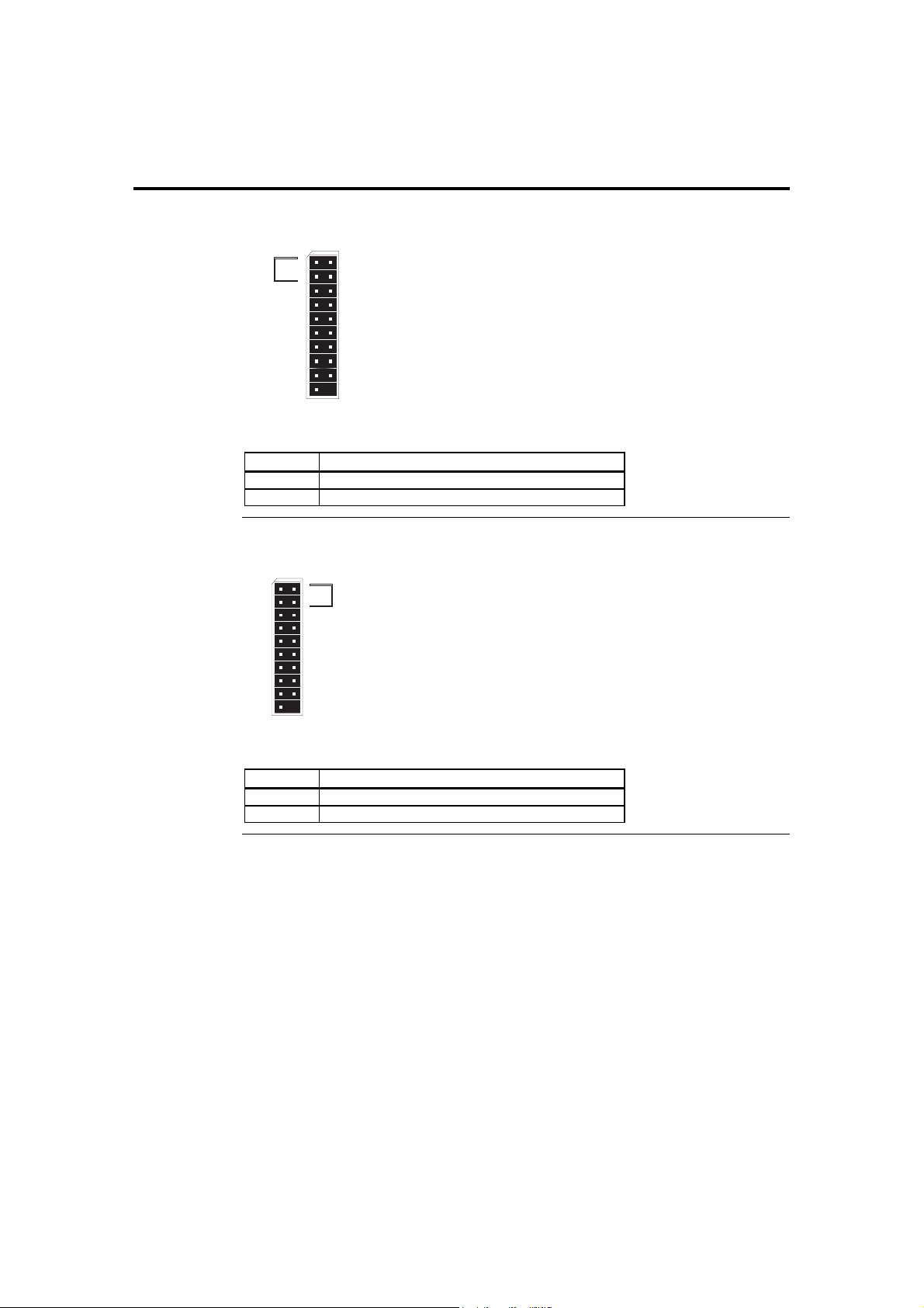
Step 5 Attach Internal Cables, Continued
J19 ATX Power Supply Soft ON/OFF Connector
J19
PWR
VCC 5V
PWR LED
VCC 3V
SF LED
VCC 5V
1
GND
3
IDE
5
7
9
11
13
15
NC
17
NC
19
Power
Button
Attach your chassis power on/off button/switch to this section of the header.
Pin Signal Name
1 #power
3 ground
J19 Reset Button Connector
J19
PWR
1
GND
3
IDE
5
VCC 5V
7
PWR LED
VCC 3V
SF LED
VCC 5V
NC
NC
10
9
12
11
14
13
16
15
18
17
19
Attach your chassis reset button/switch to this section of the header.
Pin Signal Name
2 #reset
4 ground
RST
2
GND
4
NC
6
GND
8
INT
10
GND
12
NC
14
SATA LED
16
VCC 3V
18
RST
2
Reset
Button
GND
4
NC
6
GND
8
INT
GND
NC
SATA LED
VCC 3V
Cont’d
Chapter Two : Hardware Installation 45
Page 56
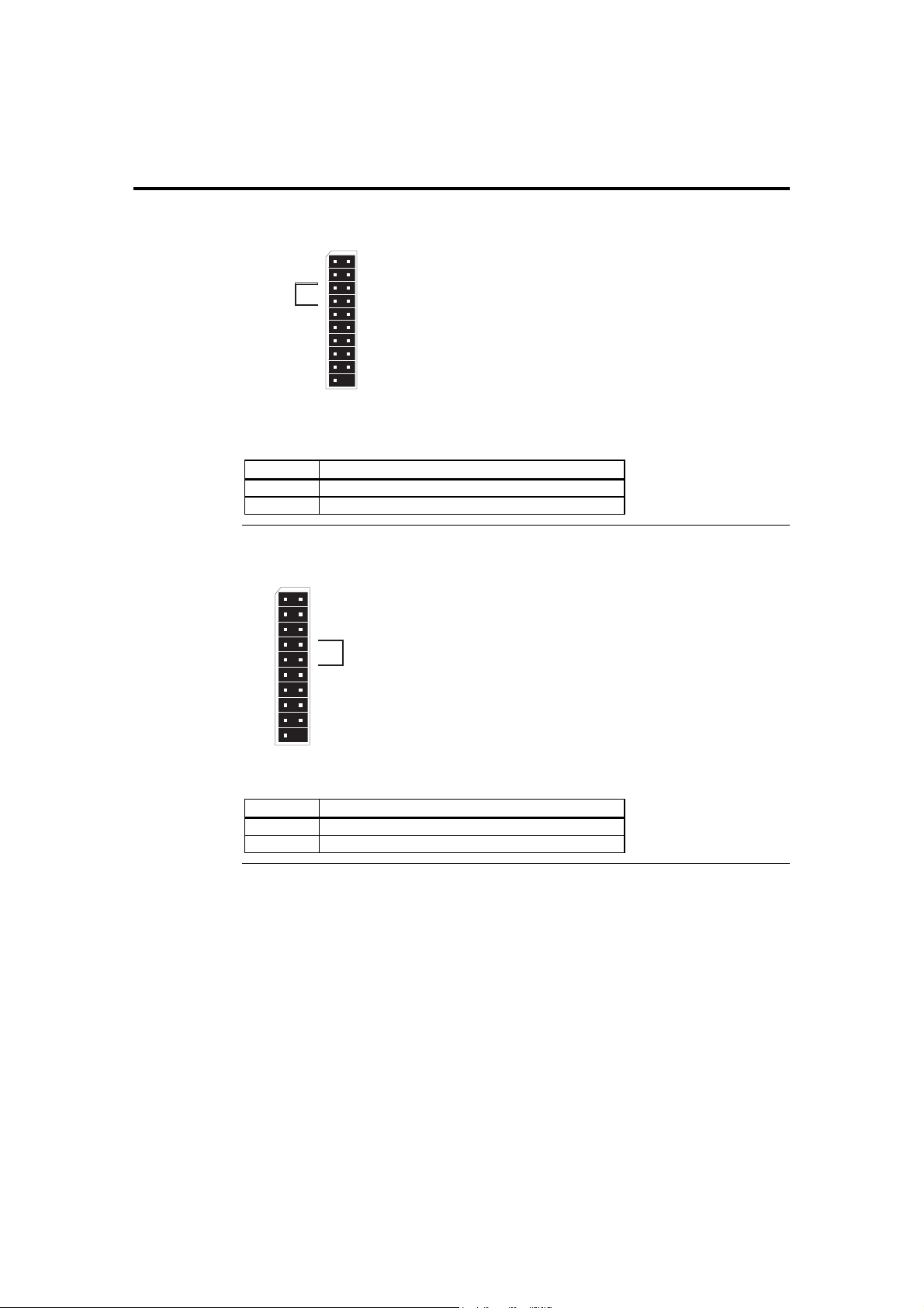
Step 5 Attach Internal Cables, Continued
J19 Parallel ATA Activity LED Connector
HDD Activity
Attach your chassis HDD activity LED to this section of the header. Check for the
correct polarity.
Pin Signal Name
5 #IDE LED
7 VCC +5 V
J19 Intrusion Sensor Connector
J19
PWR
GND
IDE
VCC 5V
PWR LED
VCC 3V
11
SF LED
13
VCC 5V
15
NC
17
NC
19
Attach your chassis intrusion sensor/trigger to this section of the header.
Pin Signal Name
8 ground
10 #intrusion sensor/trigger
J19
PWR
1
GND
3
IDE
5
LED
VCC 5V
7
PWR LED
9
VCC 3V
11
SF LED
13
VCC 5V
15
NC
17
NC
19
RST
1
3
5
7
9
2
GND
4
NC
6
GND
8
INT
10
GND
12
NC
14
SATA LED
16
VCC 3V
18
RST
2
GND
4
NC
6
GND
8
INT
10
GND
12
NC
14
SATA LED
16
VCC 3V
18
Intrusion
Sensor/Trigger
Cont’d
American Megatrends, Inc., Olympus III User’s Guide (Series 875)
46
Page 57
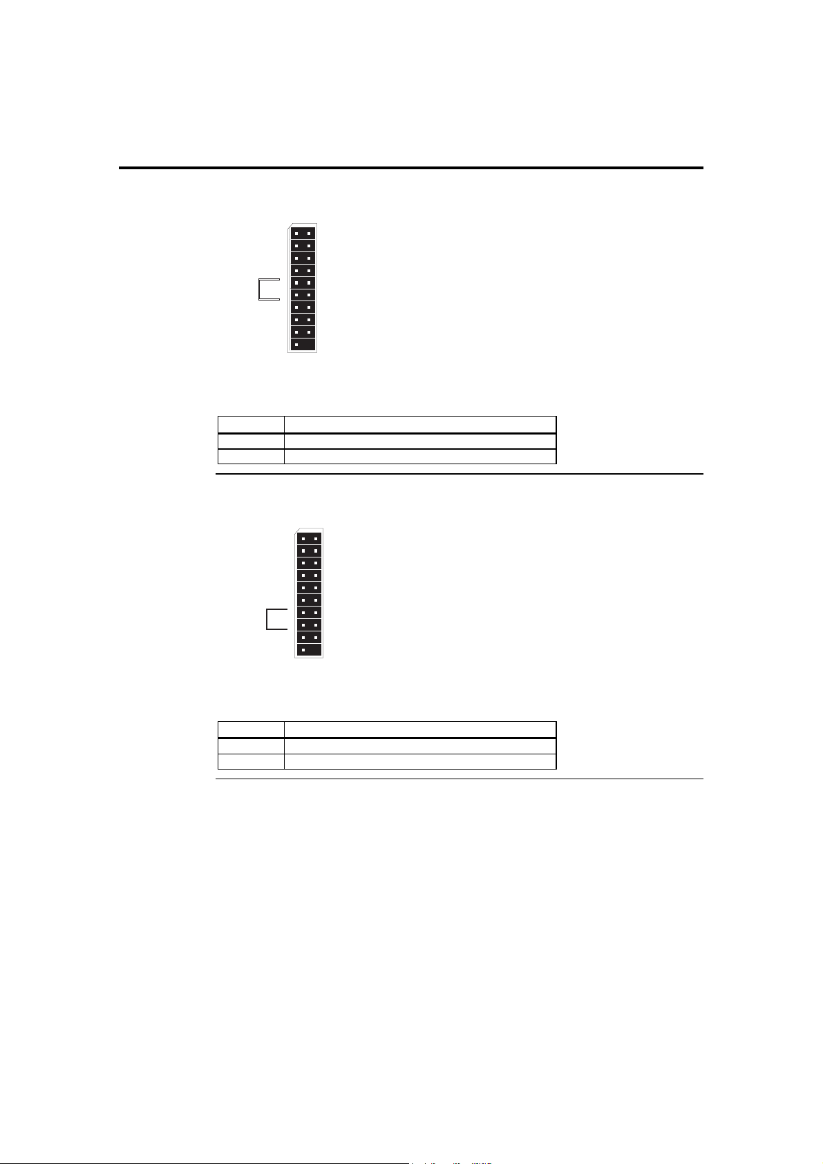
Step 5 Attach Internal Cables, Continued
J19 Power LED Connector
Power LED
Attach your chassis power LED to this section of the header. Check for the correct
polarity.
Pin Signal Name
9 #power LED
11 VCC +3 V
J19 System Fault LED Connector
System Fault
Attach your chassis system fault/warning LED to this section of the header (if applicable).
Check for the correct polarity.
Pin Signal Name
13 #system fault LED
15 VCC +5 V
LED
VCC 5V
PWR LED
VCC 3V
SF LED
VCC 5V
J19
PWR
1
GND
3
IDE
5
7
9
11
13
15
NC
17
NC
19
J19
PWR
GND
IDE
VCC 5V
VCC 3V
11
SF LED
13
VCC 5V
15
NC
17
NC
19
RST
2
GND
4
NC
6
GND
8
INT
10
GND
12
NC
14
SATA LED
16
VCC 3V
18
1
3
5
7
9
GND
4
NC
6
GND
8
INT
10
GND
12
NC
14
SATA LED
16
VCC 3V
18
RST
2
Cont’d
Chapter Two : Hardware Installation 47
Page 58
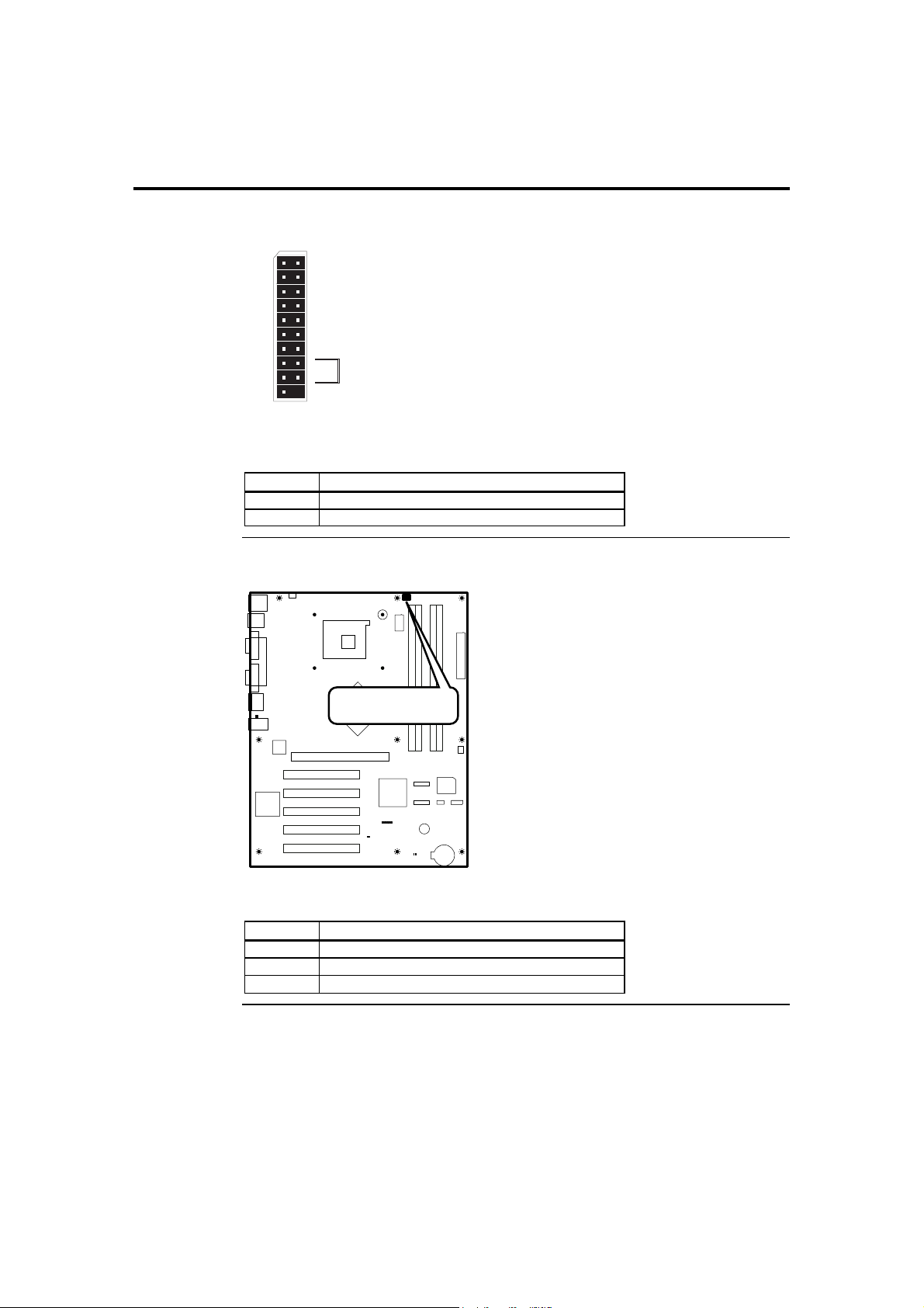
Step 5 Attach Internal Cables, Continued
J19 Serial ATA Activity LED Connector
J19
PWR
1
GND
3
IDE
5
VCC 5V
7
PWR LED
9
VCC 3V
11
SF LED
13
VCC 5V
15
NC
17
NC
19
Attach your chassis Serial ATA HDD activity LED to this section of the header (if
applicable). Check for the correct polarity.
Pin Signal Name
16 #SATA LED
18 VCC +3 V
JP2 CPU Cooling Fan Connector
2
4
6
8
10
12
14
16
18
RST
GND
NC
GND
INT
GND
NC
SATA LED
VCC 3V
Serial ATA
Activity LED
JP2
CPU Cooling Fan
Connection
Attach the CPU cooling fan to JP2.
Pin Signal Name
1 Ground
2 + 12 V
3 Tachometer Output
Cont’d
American Megatrends, Inc., Olympus III User’s Guide (Series 875)
48
Page 59
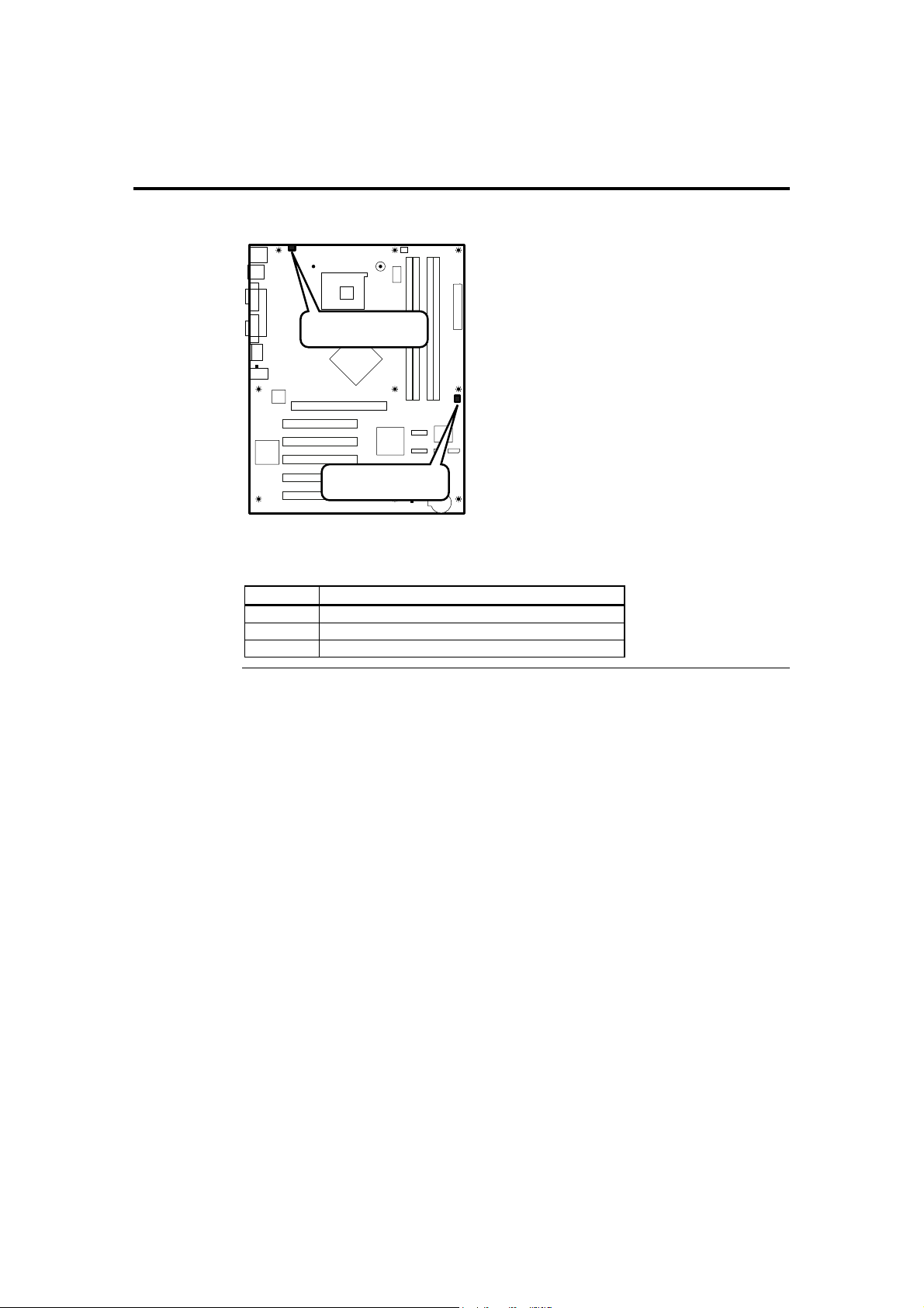
Step 5 Attach Internal Cables, Continued
JP5 and JP6 Auxiliary Cooling Fan Connector
JP5
Auxiliary Cooling
Fan Connector
JP6
Auxiliary Cooling
Fan Connector
If your chassis has an internal chassis-cooling fan, you can attach the chassis-cooling fan
to either JP5 or JP6.
Pin Signal Name
1 Ground
2 + 12 V
3 Tachometer Output
Chapter Two : Hardware Installation 49
Page 60
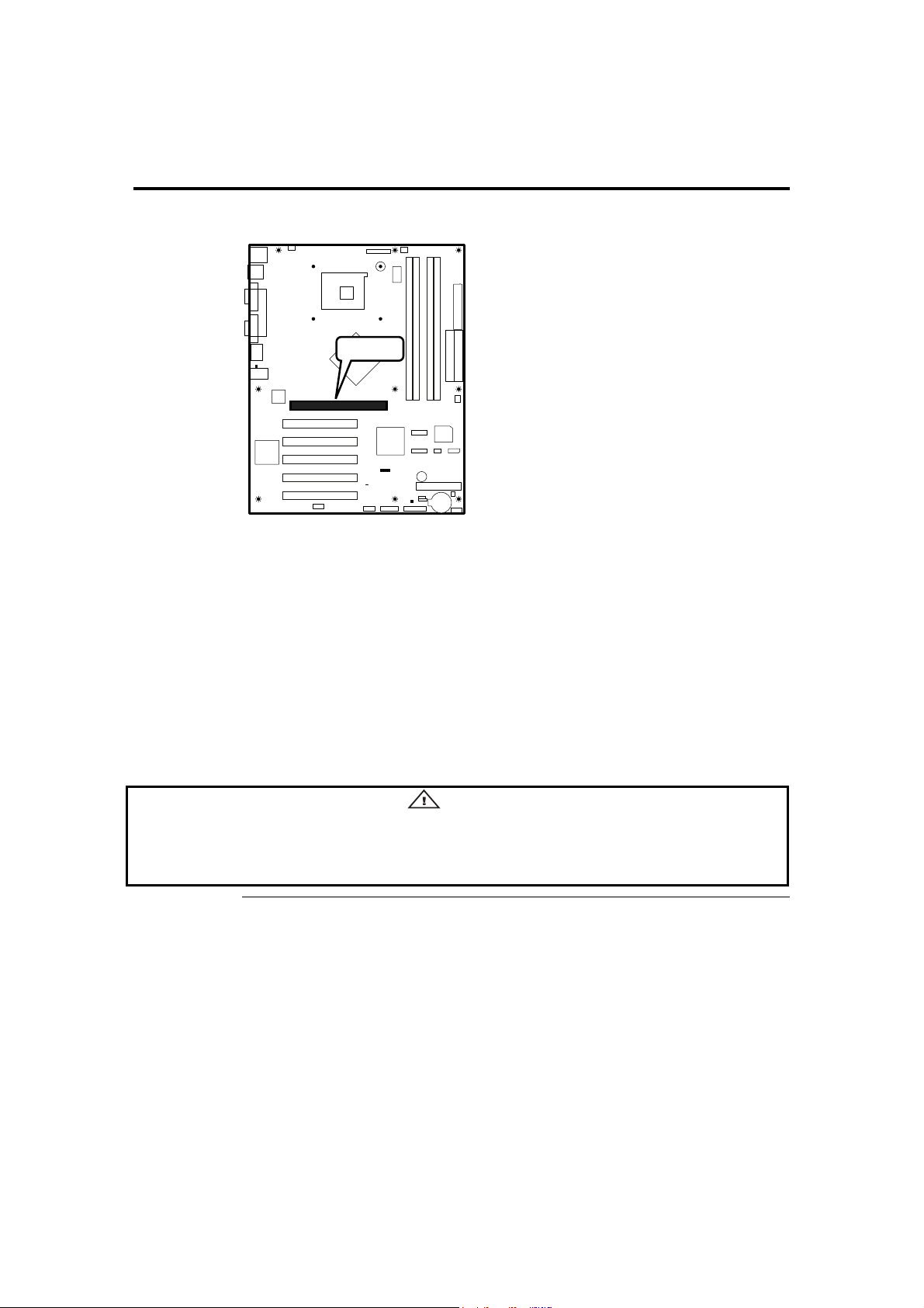
Step 6 Install Expansion Boards
AGP Slot
AGP Slot
The Olympus III incorporates one AGP slot for a video graphics adapter. The Olympus
III AGP slot can accept the following:
• 4x, 8x AGP 3.0 expansion boards with 0.8 V I/O
• 1x, 4x AGP 2.0 expansion boards with 1.5 V I/O
Note:
• AGP 2x expansion boards are NOT supported.
• Read the documentation for the expansion board before installing it into the
system.
• For easier installation of your system memory, install your system memory first
before installing an AGP expansion board.
• The AGP connector is keyed for Universal 0.8 V AGP 3.0 expansion boards or
1.5 V AGP 2.0 expansion boards only.
Warning
Do not attempt to install a legacy 3.3 V AGP expansion board. The AGP connector is not mechanically
compatible with legacy 3.3 V AGP expansion boards.
Cont’d
American Megatrends, Inc., Olympus III User’s Guide (Series 875)
50
Page 61
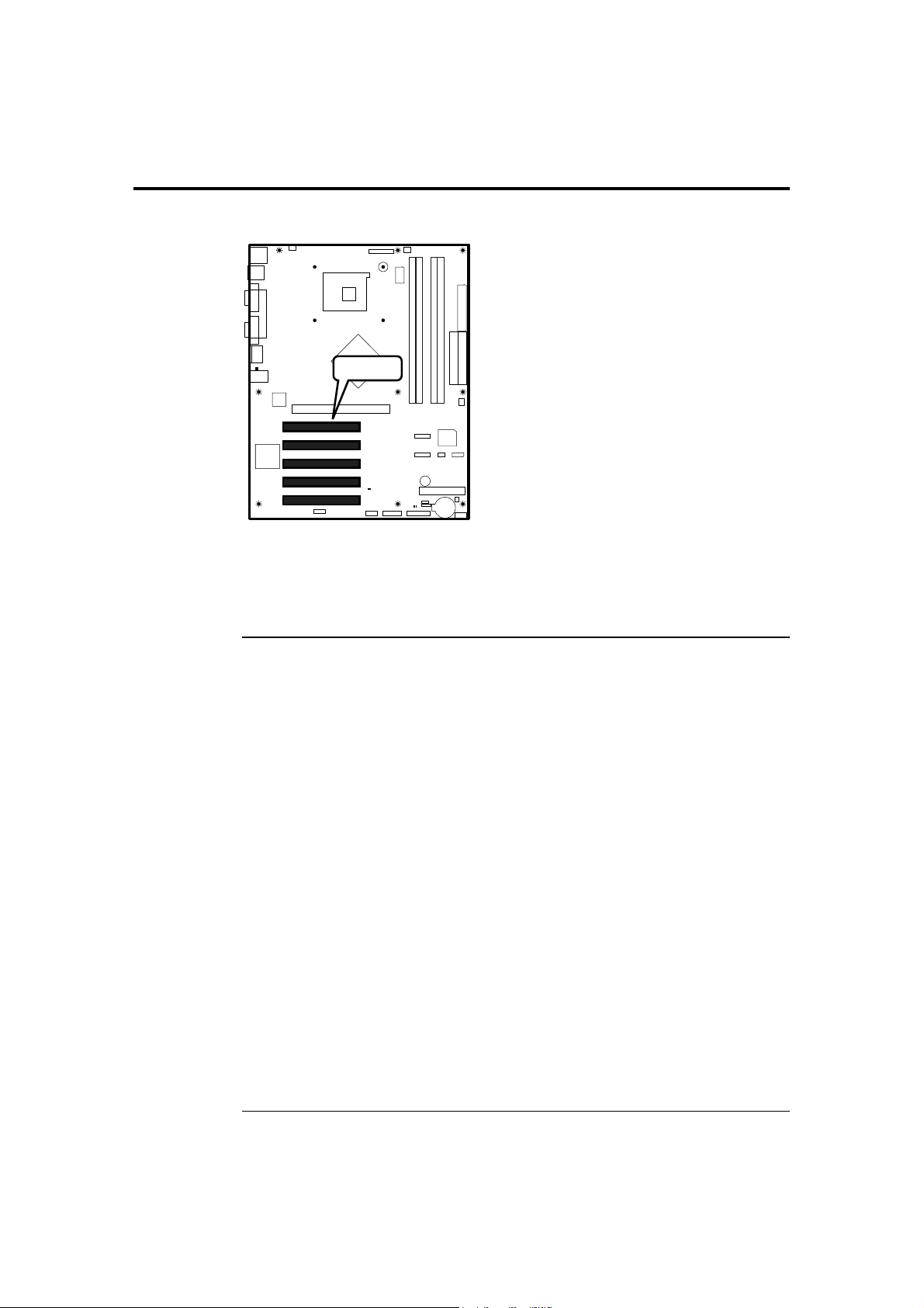
Step 6 Install Expansion Boards, Continued
PCI Slots
PCI Slots
PCI 0
PCI 1
PCI 2
PCI 3
PCI 4
The Olympus III incorporates five PCI slots for a various expansion boards. The
Olympus III PCI slots can accept standard 32 bit PCI expansion boards. All of the PCI
bus connectors are bus master capable.
Note: Read the documentation for the expansion board before installing it into the system.
PCI IRQ Routing Table
This section describes interrupt sharing and how the interrupt signals are connected
between the PCI bus connectors and onboard PCI devices. The PCI specification
specifies how interrupts can be shared between devices attached to the PCI bus. In most
cases, the small amount of latency added by interrupt sharing does not affect the
operation or throughput of the devices. In some special cases where maximum
performance is needed from a device, a PCI device should not share an interrupt with
other PCI devices. Use the following information to avoid sharing an interrupt with a PCI
add-in card.
PCI devices are categorized as follows to specify their interrupt grouping:
• INTA: By default, all expansion boards that require only one interrupt are in this
category. For almost all expansion boards that require more than one interrupt,
the first interrupt on the expansion board is also classified as INTA.
• INTB: Generally, the second interrupt on expansion boards that require two or
more interrupts is classified as INTB. (This is not an absolute requirement.)
• INTC and INTD: Generally, a third interrupt on expansion boards is classified
as INTC and a fourth interrupt is classified as INTD.
The ICH has eight programmable interrupt request (PIRQ) input signals. All PCI
interrupt sources either onboard or from a PCI expansion board connect to one of these
PIRQ signals. Some PCI interrupt sources are electrically tied together on the Olympus
III motherboard and therefore share the same interrupt. The following table shows an
example of how the PIRQ signals are routed.
Cont’d
Chapter Two : Hardware Installation 51
Page 62

Step 6 Install Expansion Boards, Continued
PCI IRQ Routing Table, Continued
For example, using the following table as a reference, assume an expansion card using
INTA is plugged into PCI slot 2. In PCI slot 2, INTA is connected to PIRQB, which is
already connected to the ICH audio controller. The expansion board in PCI slot 2 now
shares an interrupt with the onboard interrupt source.
ICH PIRQ Signal Name PCI Interrupt
Source
AGP Connector INTA INTB
USB Controller 1 INTA
SMBus Controller INTB
AC’97 ICH Audio
Controller
USB Controller 2 INTB
USB 2.0 Controller INTD
PCI 0 INTD INTA INTB INTC
PCI 1 INTC INTB INTA INTD
PCI 2 INTD INTA INTB INTC
PCI 3 INTB INTA INTC INTD
PCI 4 INTC INTA INTD INTB
Serial ATA/Serial
ATA RAID
Note: In PIC mode, the ICH can connect each PIRQ line internally to one of the IRQ signals (3,
PIRQA PIRQB PIRQC PIRQD PIRQE PIRQF PIRQG PIRQH
INTB
INTA
4, 5, 6, 7, 9, 10, 11, 12, 14, and 15). Typically, a device that does not share a PIRQ line
will have a unique interrupt. However, in certain interrupt-constrained situations, it is
possible for two or more of the PIRQ lines to be connected to the same IRQ signal.
American Megatrends, Inc., Olympus III User’s Guide (Series 875)
52
Page 63
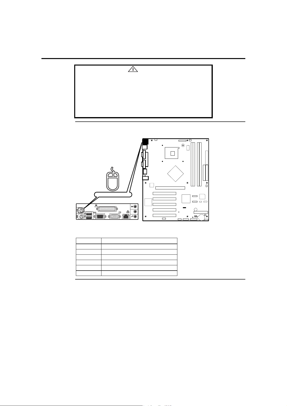
Step 7 Connecting External Cables
Only the back panel I/O connectors of the motherboard have
overcurrent protection. The internal motherboard connectors are not
overcurrent protected, and should connect only to devices inside the
system chassis, such as fans and internal peripherals. Do not use
these connectors for powering devices external to the system chassis.
A fault in the load presented by the external devices could cause
damage to the system, the interconnecting cable, and the external
devices themselves.
PS/2 Mouse Connector
Caution
PS/2 Mouse
Connect your PS/2 mouse into this port (if applicable).
Pin Signal Name
1 Mouse Data
2 Not Connected
3 Ground
4 Fused + 5 V
5 Mouse Clock
6 Not Connected
Cont’d
Chapter Two : Hardware Installation 53
Page 64
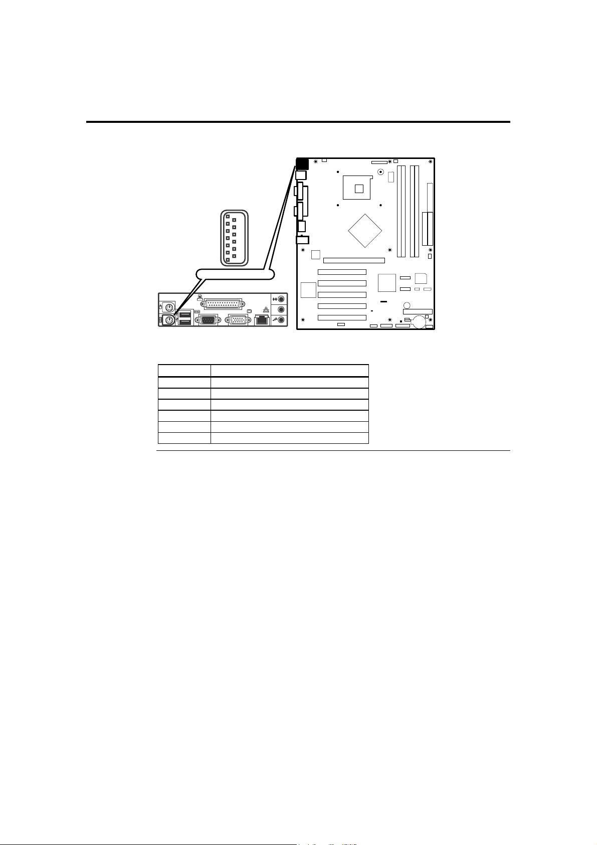
Step 7 Connecting External Cables, Continued
PS/2 Keyboard Connector
PS/2 Keyboard
Connect your PS/2 keyboard into this port (if applicable).
Pin Signal Name
1 Keyboard Data
2 Not Connected
3 Ground
4 Fused + 5 V
5 Keyboard Clock
6 Not Connected
Cont’d
American Megatrends, Inc., Olympus III User’s Guide (Series 875)
54
Page 65
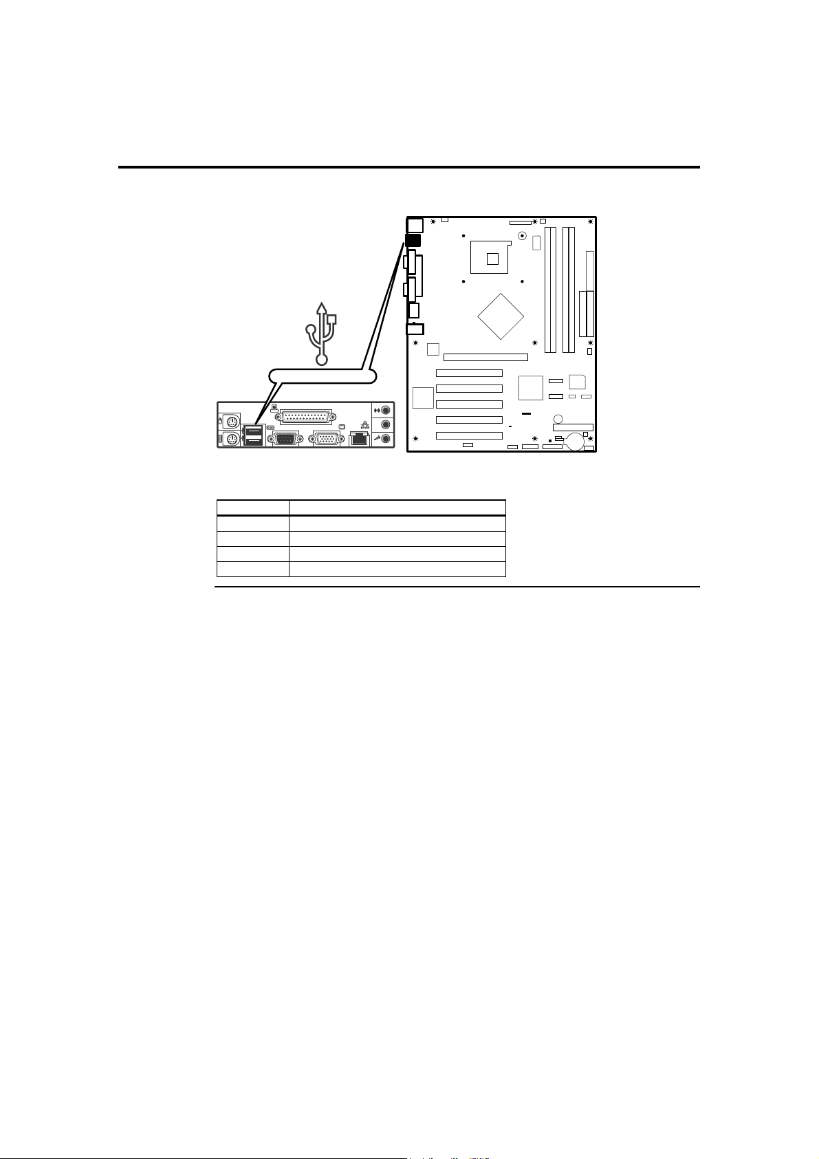
Step 7 Connecting External Cables, Continued
Dual USB Connectors
Dual USB 2.0
Connect your USB devices into this port (if applicable).
Pin Signal Name
1 Fused + 5 V
2 USBP0# / USBP1#
3 USBP0 / USBP1
4 Ground
Cont’d
Chapter Two : Hardware Installation 55
Page 66
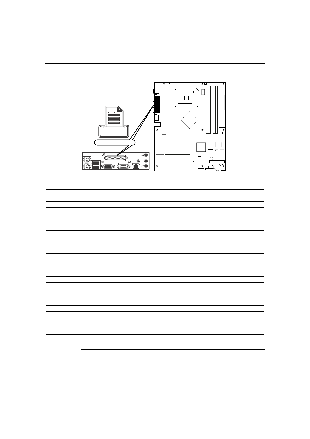
Step 7 Connecting External Cables, Continued
Parallel Port Connector
Parallel
Connect your parallel device into this port (if applicable).
Signal Name Pin
STD ECP EPP
1 Strobe # Strobe # Strobe #
2 PD0 PD0 PD0
3 PD1 PD1 PD1
4 PD2 PD2 PD2
5 PD3 PD3 PD3
6 PD4 PD4 PD4
7 PD5 PD5
8 PD6 PD6 PD6
9 PD7 PD7 PD7
10 ACK # ACK # INTR
11 BUSY BUSY #, PERIPHACK WAIT #
12 PERROR PE, ACKREVERSE # PE
13 Select Select Select
14 AUDOFD # AUDOFD #, HOSTACK DATASTB #
15 FAULT # FAULT #, PERIPHREQST # FAULT #
16 INIT # INIT #, REVERSERQST # RESET#
17 SLCTIN # SLCTIN # ADDRSTB #
18 Ground Ground Ground
19 Ground Ground Ground
20 Ground Ground Ground
21 Ground Ground Ground
22 Ground Ground Ground
23 Ground Ground Ground
24 Ground Ground Ground
25 Ground Ground Ground
Cont’d
American Megatrends, Inc., Olympus III User’s Guide (Series 875)
56
Page 67
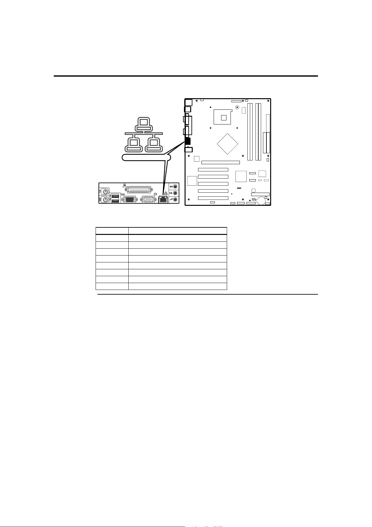
Step 7 Connecting External Cables, Continued
LAN Connector
10/100/1000 NIC
Connect your network cable into this jack (if applicable).
Pin Signal Name
1 TX+
2 TX3 RX+
4 Ground
5 Ground
6 RX7 Ground
8 Ground
Cont’d
Chapter Two : Hardware Installation 57
Page 68
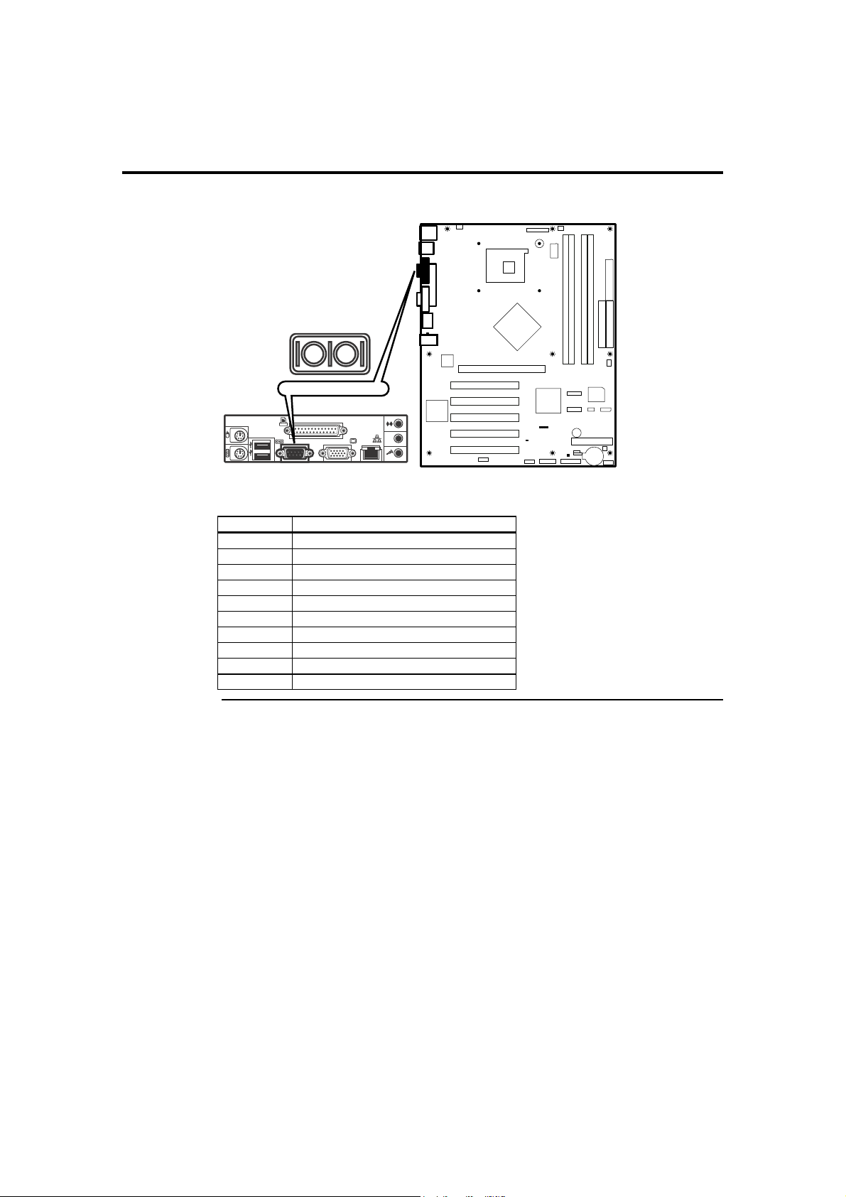
Step 7 Connecting External Cables, Continued
Serial Port Connector
Serial Port
Connect your serial device into this port (if applicable).
Pin Signal Name
1 DCD (Data Carrier Detect)
2 DSR (Data Set Ready)
3 SIN# (Serial Data In)
4 RTS (Request to Send)
5 SOUT# (Serial Data Out)
6 CTS (Clear to Send)
7 DTR (Data Terminal Ready)
8 RI (Ring Indicator)
9 Ground
10 Key
Cont’d
American Megatrends, Inc., Olympus III User’s Guide (Series 875)
58
Page 69
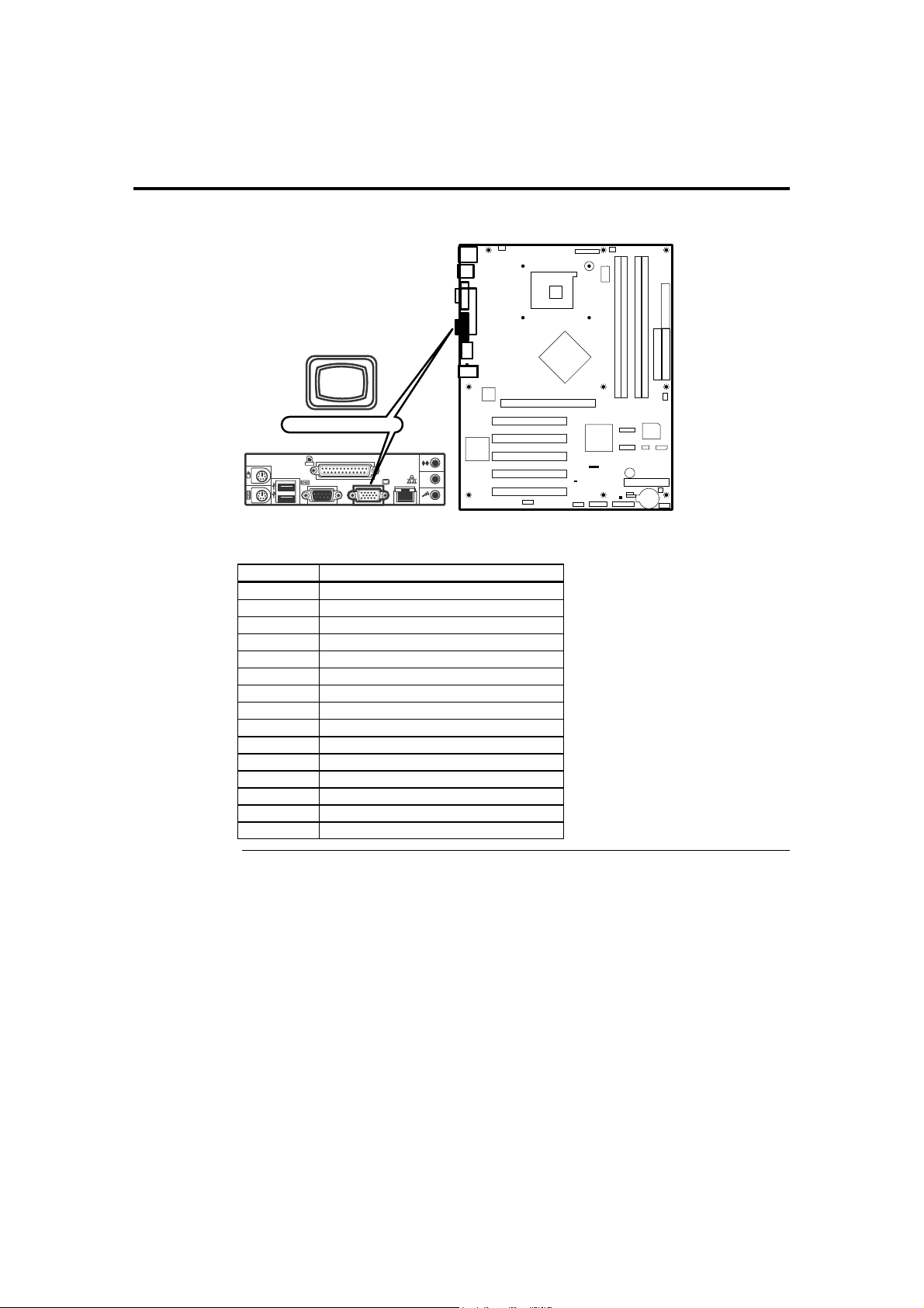
Step 7 Connecting External Cables, Continued
VGA Connector
VGA Connector
Connect your monitor into this connector (if applicable).
Pin Signal Name
1 Red
2 Green
3 Blue
4 +5V
5 Ground
6 Ground
7 Ground
8 Ground
9 +5V
10 Ground
11 +5V
12 5VDDCDA
13 5VHSYNC
14 5VVSYNC
15 5VDDCCL
Cont’d
Chapter Two : Hardware Installation 59
Page 70
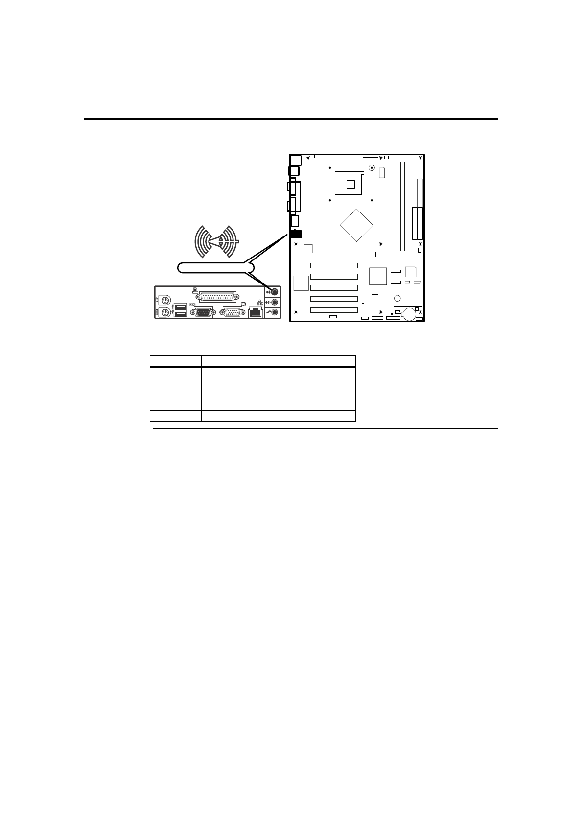
Step 7 Connecting External Cables, Continued
Line In Audio Jack
Line In
Connect your audio device into this jack (if applicable).
Pin Signal Name
1 Line Right
2 Ground
3 Ground
4 Line Left
5 Ground
Cont’d
American Megatrends, Inc., Olympus III User’s Guide (Series 875)
60
Page 71
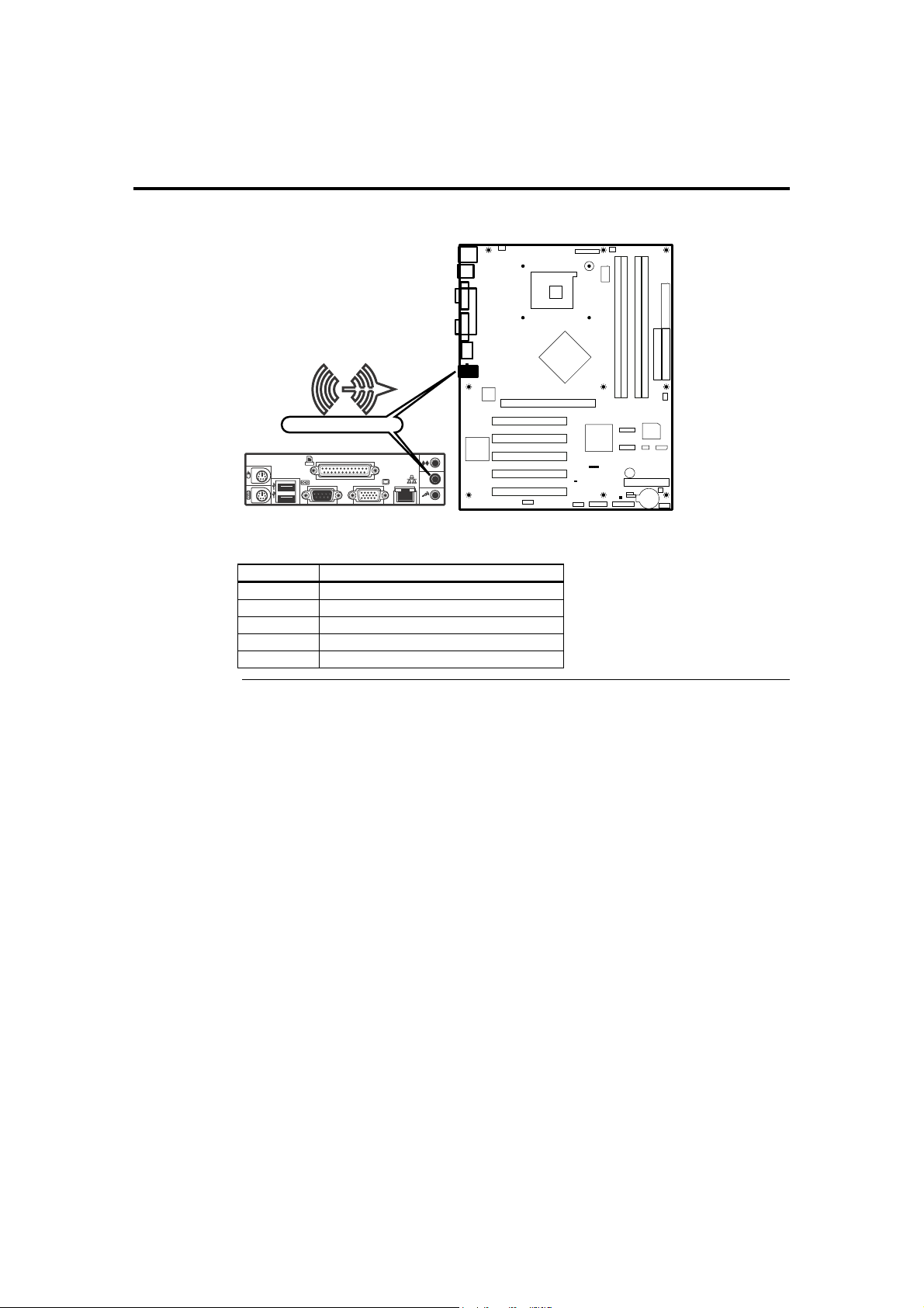
Step 7 Connecting External Cables, Continued
Speaker Out Audio Jack
Speaker Out
Connect your speaker into this jack (if applicable).
Pin Signal Name
1 Audio Right
2 Ground
3 Ground
4 Audio Left
5 Ground
Cont’d
Chapter Two : Hardware Installation 61
Page 72
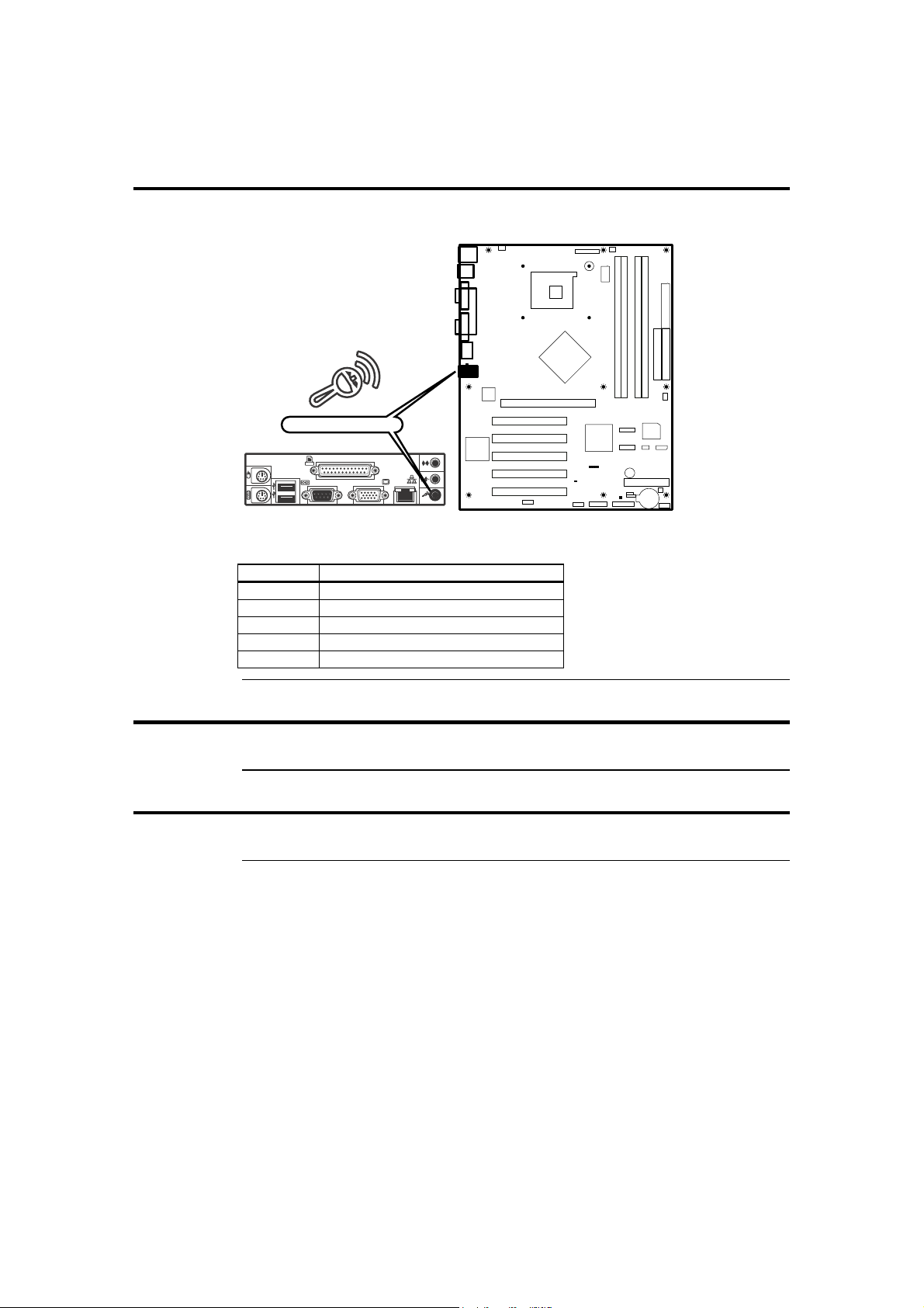
Step 7 Connecting External Cables, Continued
Microphone Audio Jack
Microphone
Connect your microphone into this jack (if applicable).
Pin Signal Name
1 +5V
2 Ground
3 Ground
4 Mic
5 Ground
Step 8 Install Drivers
Install the software drivers.
Step 9 Test and Configure
Test the board and make sure the configurations are correct.
American Megatrends, Inc., Olympus III User’s Guide (Series 875)
62
Page 73

Chapter 3 AMIBIOS Setup
Overview
In PCI servers, the system parameters (such as amount of memory, type of disk drives
and video displays, and many other elements) are stored in CMOS RAM. Unlike the
system memory that is used for standard system memory, CMOS RAM requires very
little power. When the server is powered off, a back-up battery provides power to CMOS
RAM that retains the system parameters. Every time the server is powered on, the server
is configured with the values stored in CMOS RAM by the system BIOS, which gains
control when the server is powered on.
The system parameters are configured by a system BIOS Setup utility. Historically, BIOS
setup utilities have been character-based, required keyboard input, and have had user
interfaces that were not very intuitive. The BIOS chips acts as an interface between the
processor and the rest of the server board’s components. This chapter describes the
parameters in the AMIBIOS Setup Utility and explains how to modify the settings for the
configuration of your Olympus III motherboard.
Caution
The default settings are sufficient for most system operations. Changes to the default settings can affect
the performance/reliability/stability of your Olympus III motherboard.
Starting AMIBIOS Setup
AMIBIOS(C)2003 Amrican Megatrends, Inc.
BIOS Date: 10/23/03 13:26:09 Ver: 08.00.10
CPU : Intel(R)Pentium(R) 4 CPU 3.06GHz
Speed : 3.06 GHz
Press DEL to run Setup (F4 On Remote Keyboard)
DDR Frequency 333 Mhz, Single-Channel or Virtual Single-Channel
Checking NVRAM...
Initializing USB Controllers .. Done
512MB OK
Auto-Detecting Pri Master...IDE Hard Disk
Pri MAster: ST34311A 6.01
Ultra DMA Mode-2. S.M.A.R.T. Capable and Status OK
Auto-detecting USB Mass Storage Devices ..
00 USB mass storage devices found and configured.
(C) American Megatrends, Inc.
63-0100-000001-00101111-102303-CANTERWOOD-AMI87527-Y2KC
423C
As POST executes, press the <DEL> key to enter the AMIBIOS Setup Utility.
Chapter Three : AMIBIOS Setup
Cont’d
63
Page 74
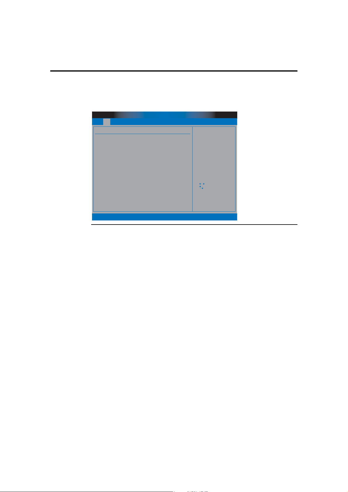
Starting AMIBIOS Setup, Continued
AMIBIOS Setup Menu
The AMIBIOS Setup Utility appears as shown below. Each menu item is described in this
chapter.
BIOS SETUP UTILITY
Main Advanced PCIPnP Security
System Overview
AMIBIOS
Version : 08.00.10
Build Date : 10/09/03
ID : AMIB7524
Processor
Type :
Speed :
Count :
System Memory
Size : 1024MB
System Time
System Date
Intel (R) Pentium (R) 4 CPU 3.06GHz
3066MHz
1
Boot
[03:02:37]
[Tue 10/14/2003]
Chipset
Use [ENTER], [TAB]
or [SHIFT-TAB] to
select a field.
Use [+] or [-] to
Configure System Time.
+ Tab
F1
F10
ESC
Power
Select Screen
Select Item
Change Field
Select Field
General Help
Save and Exit
Exit
Exit
v02.53 (C) Copyright 1985-2003, American Megatrends, Inc.
American Megatrends, Inc., Olympus III User’s Guide (Series 875)
64
Page 75
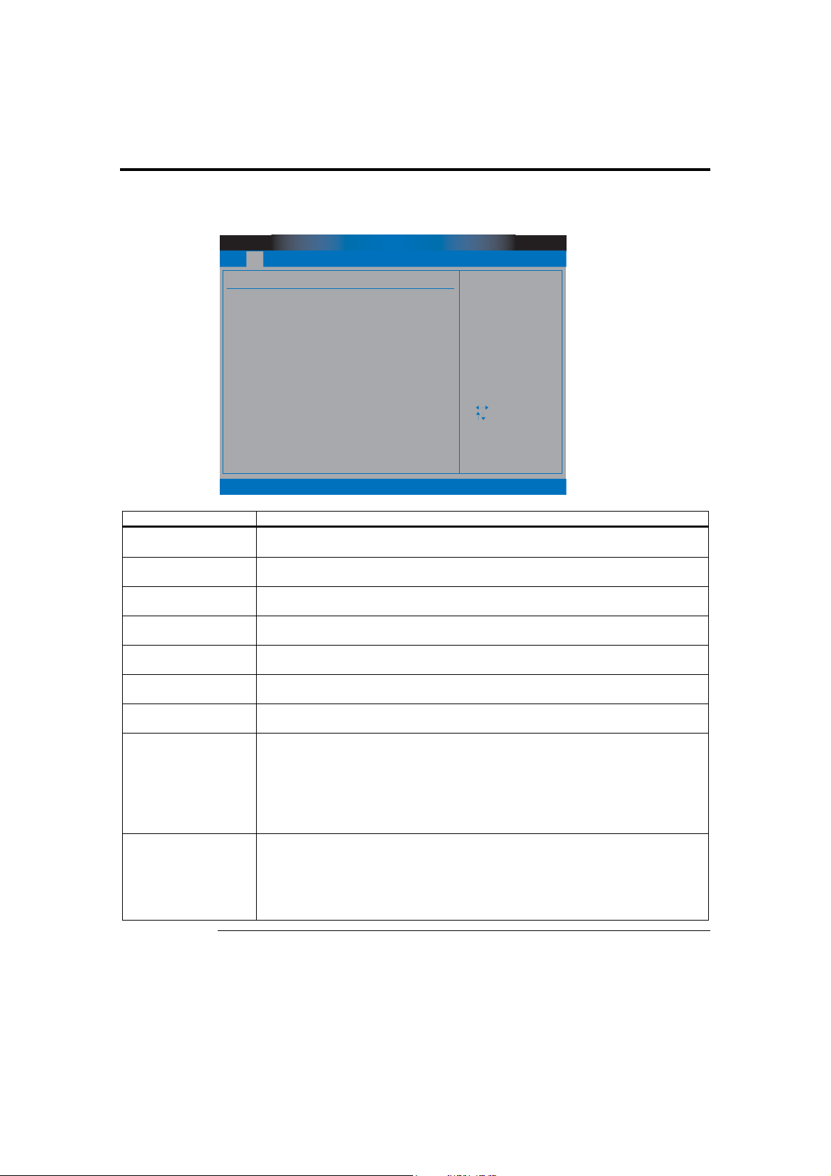
Section 1 Main Setup
Select Main from the main menu of the AMIBIOS Setup Utility. All Main setup options
are described in this section. The Main setup screen is displayed below:
Main Advanced PCIPnP Security
System Overview
AMIBIOS
Version : 08.00.10
Build Date : 10/09/03
ID : AMIB7524
Processor
Type :
Speed :
Count :
System Memory
Size : 1024MB
System Time
System Date
BIOS SETUP UTILITY
Boot
Intel (R) Pentium (R) 4 CPU 3.06GHz
3066MHz
1
[03:02:37]
[Tue 10/14/2003]
Chipset
Use [ENTER], [TAB]
or [SHIFT-TAB] to
select a field.
Use [+] or [-] to
Configure System Time.
+ Tab
F1
F10
ESC
Power
Select Screen
Select Item
Change Field
Select Field
General Help
Save and Exit
Exit
Exit
v02.53 (C) Copyright 1985-2003, American Megatrends, Inc.
Field Description
AMIBIOS Version This field displays the AMIBIOS version number. This field cannot be modified and is
grayed out.
BIOS Build Date This field displays the AMIBIOS build date. This field cannot be modified and is grayed
out.
BIOS ID This field displays the AMIBIOS identification number. This field cannot be modified
and is grayed out.
Processor Type This field displays the processor manufacturer information. This field cannot be modified
and is grayed out.
Processor Speed This field displays the speed of the processor. This field cannot be modified and is grayed
out.
Processor Count This field displays the number of physical processors are on the motherboard. This field
cannot be modified and is grayed out.
System Memory This field displays the amount of system memory that is physically installed in the
Olympus III motherboard. This field cannot be modified and is grayed out.
System Time Use this option to change the system time. Highlight Time using the arrow keys. Enter
new values through the keyboard. Press the <TAB> key or the arrow keys to move
between fields. The time is entered in HH:MM:SS format. The time is in 24-hour format.
For example, 5:30 a.m. appears as 05:30:00, and 5:30 p.m. as 17:30:00.
Press <PgUp> or <PgDn> after you have selected an option to display the complete list of
valid settings in the bottom section of the screen.
System Date Use this option to change the system date. Highlight Date using the arrow keys. Enter
new values through the keyboard. Press the <TAB> key or the arrow keys to move
between fields. The date must be entered in MM/DD/YYYY format.
Press <PgUp> or <PgDn> after you have selected an option to display the complete list of
valid settings in the bottom section of the screen.
Chapter Three : AMIBIOS Setup
65
Page 76
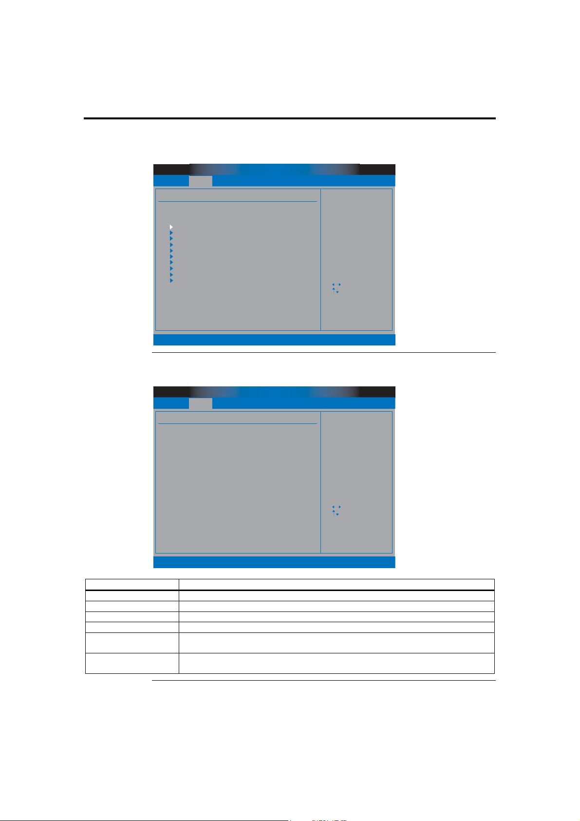
Section 2 Advanced Setup
Select Advanced from the main menu of the AMIBIOS Setup Utility. All Advanced setup
options are described in this section. The Advanced setup screen is displayed below:
Main Advanced
Advanced Settings
WARNING : Setting wrong values in below sections
may cause system to malfunction.
CPU Configuration
IDE Configuration
Floppy Configuration
SuperIO Configuration
ACPI Configuration
DMI Event Logging
Hardware Health Configuration
MPS Configuration
Remote Access Configuration
USB Configuration
BIOS SETUP UTILITY
PCIPnP Security
Boot
Chipset
ExitPower
Configure CPU.
Select Screen
Select Item
Enter Go to Sub Screen
F1
General Help
F10
Save and Exit
ESC
Exit
v02.53 (C) Copyright 1985-2003, American Megatrends, Inc.
CPU Configuration
BIOS SETUP UTILITY
Main Advanced
Configure Advanced CPU Settings
Manufacturer : Intel
Brand String : Intel (R) Pentium (R) 4 CPU 3.06GHz
Frequency : 3.06HHz
FSB Speed : 533MHz
Cache L1 : 8 KB
Cache L2 : 512 KB
Cache L3 : 0 KB
Ratio Status : Locked
Ratio Actual Value : 23
Ratio CMOS Settings : [ 8]
VID CMOS Settings : [ 62]
L3 Cache [Enabled]
Hyper Threading Technology [Enabled]
PCIPnP Security
v02.53 (C) Copyright 1985-2003, American Megatrends, Inc.
Boot
Chipset
ExitPower
Sets the Ratio
Between CPU Core
Clock and the FSB
Frequency. NOTE:
If an invalid ratio
is set in CMOS
the actual and
setpoint values may
differ. Ratio of
Zero allows external
ratio control.
Select Screen
Select Item
Enter Update
F1
General Help
F10
Save and Exit
ESC
Exit
Field Description
Manufacturer This field displays the manufacturer of the processor that is installed on the motherboard.
Brand String This field displays the hard coded text string the is contained in the processor.
Frequency This field displays the operating frequency of the processor.
FSB Speed This field displays the front side bus speed of the processor.
Cache L1 This field displays the level one cache that is reported by the processor. Typically, the
higher this number the greater the performance.
Cache L2 This field displays the level two cache that is reported by the processor. Typically, the
higher this number the greater the performance.
Cont’d
American Megatrends, Inc., Olympus III User’s Guide (Series 875)
66
Page 77
Section 2 Advanced Setup, Continued
CPU Configuration, Continued
Field Description
Cache L3 This field displays the level three cache that is reported by the processor. Typically, the
higher this number the greater the performance.
Ratio Status This field displays the current setting of the CPU clock multiplier ratio. Typically this
setting is locked by the processor and cannot be changed. However, over-clocking the
processor is very common and it is very desirable to change this setting.
Ratio Actual Value This field displays the CPU clock multiplier ratio.
Ratio CMOS Settings This field displays the CPU Ratio in CMOS. If an invalid ratio is set in CMOS, then
actual and setpoint values may differ.
VID CMOS Settings This field displays the CPU Voltage Identification code (VID) configuration as set in the
CMOS.
L3 Cache
Option Description
Disabled Set this value to prevent the BIOS from using level three cache. This value is typically
used to troubleshoot a problem.
Enabled Set this value to turn on level three cache. This is the default setting.
Hyper Threading Technology
Option Description
Disabled Set this value to turn off Hyper Threading technology in your processor.
Enabled Set this value to turn on Hyper Threading technology in your processor. This is the
IDE Configuration
Hyper Threading Technology is the technology being built into many of Intel®
Pentium® 4 processors. It allows a single processor to act as two independent processors.
default setting.
BIOS SETUP UTILITY
Main Advanced
IDE Configuration
IDE Configuration [P-ATA Only]
S-ATA Running Enhanced Mode [Yes]
P-ATA Channel Selection [Both]
S-ATA Ports Definition [P0-3rd.P1-4th.]
Configure S-ATA as RAID [No]
Primary IDE Master : [Hard Disk]
Primary IDE Slave : [ATAPI CDROM]
Secondary IDE Master : [Not Detected]
Secondary IDE Slave : [Not Detected]
Third IDE Master : [Not Detected]
Third IDE Slave : [Not Detected]
Fourth IDE Master : [Not Detected]
Fourth IDE Slave : [Not Detected]
Hard Disk Write Protect [Disabled]
IDE Detect Time Out (Sec) [35]
ATA (PI) 80Pin Cable Detection [Host & Device]
PCIPnP Security
Boot
Chipset
ExitPower
PCI ATA LEGACY ATA
MODE HELP
Select Screen
Select Item
+ -
Change Option
F1
General Help
F10
Save and Exit
ESC
Exit
v02.53 (C) Copyright 1985-2003, American Megatrends, Inc.
Cont’d
Chapter Three : AMIBIOS Setup
67
Page 78
Section 2 Advanced Setup, Continued
IDE Configuration, Continued
Option Description
Disabled This option turns off all onboard ATA support in the BIOS.
P-ATA Only This option turns on parallel ATA support only in the BIOS.
S-ATA Only This option turns on serial ATA support only in the BIOS.
BIOS SETUP UTILITY
Main Advanced
IDE Configuration
IDE Configuration [S-ATA Only]
S-ATA Ports Definition [P0-1st.P1-2nd.]
Primary IDE Master : [Hard Disk]
Primary IDE Slave : [ATAPI CDROM]
Secondary IDE Master : [Not Detected]
Secondary IDE Slave : [Not Detected]
Third IDE Master : [Not Detected]
Third IDE Slave : [Not Detected]
Fourth IDE Master : [Not Detected]
Fourth IDE Slave : [Not Detected]
Hard Disk Write Protect [Disabled]
IDE Detect Time Out (Sec) [35]
ATA (PI) 80Pin Cable Detection [Host & Device]
PCIPnP Security
Boot
Chipset
ExitPower
PCI ATA LEGACY ATA
MODE HELP
Select Screen
Select Item
+ -
Change Option
F1
General Help
F10
Save and Exit
ESC
Exit
v02.53 (C) Copyright 1985-2003, American Megatrends, Inc.
P-ATA & S-ATA This option turns on both parallel and serial ATA support in the BIOS.
BIOS SETUP UTILITY
Main Advanced
IDE Configuration
IDE Configuration [P-ATA & S-ATA]
Combined Mode Option [P-ATA 1st Channel]
S-ATA Ports Definition [P0-Master/P1-Slave]
Primary IDE Master : [Hard Disk]
Primary IDE Slave : [ATAPI CDROM]
Secondary IDE Master : [Not Detected]
Secondary IDE Slave : [Not Detected]
Third IDE Master : [Not Detected]
Third IDE Slave : [Not Detected]
Fourth IDE Master : [Not Detected]
Fourth IDE Slave : [Not Detected]
Hard Disk Write Protect [Disabled]
IDE Detect Time Out (Sec) [35]
ATA (PI) 80Pin Cable Detection [Host & Device]
PCIPnP Security
v02.53 (C) Copyright 1985-2003, American Megatrends, Inc.
Boot
Chipset
ExitPower
PCI ATA LEGACY ATA
MODE HELP
Select Screen
Select Item
+ -
Change Option
F1
General Help
F10
Save and Exit
ESC
Exit
S-ATA Running Enhanced Mode
Option Description
Yes This value turns on Native mode support for your serial ATA controller. This is the
default value.
No This value turns off Native mode support for your serial ATA controller.
Cont’d
American Megatrends, Inc., Olympus III User’s Guide (Series 875)
68
Page 79

Section 2 Advanced Setup, Continued
P-ATA Channel Selection
Option Description
Primary This value turns on parallel ATA support only on the Primary IDE connector and not the
Secondary connector.
Secondary This value turns on parallel ATA support only on the Secondary IDE connector and not
the Primary connector.
Both This value turns on parallel ATA support on the Primary IDE connector and the
Combined Mode
Option Description
P-ATA 1st Channel This setting allows the motherboard to boot off the parallel ATA connectors first. This is
S-ATA 1st Channel This setting allows the motherboard to boot off the serial ATA connectors first.
S-ATA Ports Definition
This setting allows you to assign the serial ATA port locations.
Option Description
P0-3rd./P1-4th. This setting assigns CN4 (SATA 0) as the third hard disk location and CN5 (SATA 1) as
P0-4th./P1-3rd. This setting assigns CN5 (SATA 1) as the third hard disk location and CN4 (SATA 0) as
Configure S-ATA as RAID
Option Description
No This value turns off the BIOS level RAID level 0 boot support on the serial ATA
Yes This value turns on the BIOS level RAID level 0 boot support on the serial ATA
Hard Disk Write Protect
Option Description
Disabled This value allows you to write to the hard disk drive. This is the default value.
Enabled This value prevents you from making any changes to the hard disk drive. Essentially, the
Secondary connector. This is the default value.
the default value.
the forth hard disk location. For the location of these two connectors, see the Board
Layout diagram in Chapter One, Hardware Specifications and Supported Features. This
is the default value.
the forth hard disk location. For the location of these two connectors, see the Board
Layout diagram in Chapter One, Hardware Specifications and Supported Features.
connectors located at CN4 (SATA 0) and CN5 (SATA 1). This is the default value.
connectors located at CN4 (SATA 0) and CN5 (SATA 1).
hard disk drive acts as a CD-ROM disc would.
Cont’d
Chapter Three : AMIBIOS Setup
69
Page 80

Section 2 Advanced Setup, Continued
IDE Detect Time Out (Sec)
Option Description
0 This value prevents the system from waiting any amount of time when trying to detect
the hard disk drives.
5 This value allows the system to wait five seconds when trying to detect the hard disk
drives.
10 This value allows the system to wait ten seconds when trying to detect the hard disk
drives.
15 This value allows the system to wait fifteen seconds when trying to detect the hard disk
drives.
20 This value allows the system to wait twenty seconds when trying to detect the hard disk
drives.
25 This value allows the system to wait twenty-five seconds when trying to detect the hard
disk drives.
30 This value allows the system to wait thirty seconds when trying to detect the hard disk
drives.
35 This value allows the system to wait thirty-five seconds when trying to detect the hard
ATAPI 80 Pin Cable Detection
Option Description
Host & Device This setting allows the parallel ATA controller and ATA device to detect the type of
Host This setting allows the parallel ATA controller to detect the type of ATA cable being
Device This setting allows the ATA device to detect the type of ATA cable being used.
disk drives. This is the default value.
ATA cable being used. This is the default value.
used.
Cont’d
American Megatrends, Inc., Olympus III User’s Guide (Series 875)
70
Page 81
Section 2 Advanced Setup, Continued
Primary and Secondary IDE Master : Hard Disk Drive
BIOS SETUP UTILITY
Main Advanced
Primary IDE Master
Device
Vendor
Size
LBA Mode
Block Mode
PIO Mode
Async DMA
Ultra DMA
S.M.A.R.T
Type
LBA/ Large Mode
Block (Multi - Sector Transfer)
PIO Mode
DMA Mode
S.M.A.R.T.
23Bit Data Transfer
: Hard Disk
: Maxtor 4G160Jb
: 163.9GB
: Supported
: 16Sectors
: 4
: MultiWord DMA-2
: Ultra DMA-6
: Supported
PCIPnP Security
Boot
[Auto]
[Auto]
[Auto]
[Auto]
[Auto]
[Auto]
[Disabled]
Chipset
ExitPower
Select the type
of device connected
to the system.
Select Screen
Select Item
+ -
Change Option
F1
General Help
F10
Save and Exit
ESC
Exit
v02.53 (C) Copyright 1985-2003, American Megatrends, Inc.
Field Description
Device Type of device, such as hard disk drive.
Vendor Manufacturer of the device.
Size The size of the device.
LBA Mode LBA (Logical Block Addressing) is a method of addressing data on a disk drive. In LBA
mode, the maximum drive capacity is 137 GB. For drive capacities over 137 GB, your
AMIBIOS is equipped with 48-bit LBA mode addressing.
Block Mode Block mode boosts IDE drive performance by increasing the amount of data transferred.
Only 512 bytes of data can be transferred per interrupt if block mode is not used. Block
mode allows transfers of up to 64 KB per interrupt.
PIO Mode IDE PIO mode programs timing cycles between the IDE drive and the programmable IDE
controller. As the PIO mode increases, the cycle time decreases.
Async DMA This indicates the highest Asynchronous DMA Mode that is supported.
Ultra DMA This indicates the highest Synchronous DMA Mode that is supported.
SMART Self-Monitoring Analysis and Reporting Technology protocol used by IDE drives of some
manufacturers to predict drive failures.
Cont’d
Chapter Three : AMIBIOS Setup
71
Page 82

Section 2 Advanced Setup, Continued
Primary and Secondary IDE Master : ATAPI CD ROM
BIOS SETUP UTILITY
Main Advanced
Primary IDE Master
Device
Vendor
LBA Mode
PIO Mode
Async DMA
Ultra DMA
PCIPnP Security
: ATAPI CDROM
: CDU5211
: Supported
: 4
: MultiWord DMA-2
: Ultra DMA-2
Boot
Chipset
ExitPower
Select the type
of device connected
to the system.
Type
PIO Mode
DMA Mode
v02.53 (C) Copyright 1985-2003, American Megatrends, Inc.
[Auto]
[Auto]
[Auto]
+ F1
F10
ESC
Select Screen
Select Item
Change Option
General Help
Save and Exit
Exit
Field Description
Device Type of device, such as hard disk drive.
Vendor Manufacturer of the device.
LBA Mode LBA (Logical Block Addressing) is a method of addressing data on a drive.
PIO Mode IDE PIO mode programs timing cycles between the IDE drive and the programmable IDE
controller. As the PIO mode increases, the cycle time decreases.
Async DMA This indicates the highest Asynchronous DMA Mode that is supported.
Ultra DMA This indicates the highest Synchronous DMA Mode that is supported.
Type
This option sets the type of device that the AMIBIOS attempts to boot from after the
Power-On Self-Test (POST) has completed. The Optimal and Fail-Safe default setting is
Auto.
Option Description
Not Installed Set this value to prevent the BIOS from searching for an IDE disk drive on the specified
channel.
Auto Set this value to allow the BIOS auto detect the IDE disk drive type attached to the specified
channel. This setting should be used if an IDE hard disk drive is attached to the specified
channel. This is the default setting.
CDROM This option specifies that an IDE CD-ROM drive is attached to the specified IDE channel. The
BIOS will not attempt to search for other types of IDE disk drives on the specified channel.
ARMD This option specifies an ATAPI Removable Media Device.
This includes, but is not limited to:
• ZIP
• LS-120
Cont’d
American Megatrends, Inc., Olympus III User’s Guide (Series 875)
72
Page 83

Section 2 Advanced Setup, Continued
LBA/Large Mode
LBA (Logical Block Addressing) is a method of addressing data on a disk drive. In LBA
mode, the maximum drive capacity is 137 GB. The Optimal and Fail-Safe default setting
is Auto.
Note: For hard disk drive capacities over 137 GB, your AMIBIOS is equipped with 48-bit LBA
mode addressing.
Option Description
Disabled Set this value to prevent the BIOS from using Large Block Addressing mode control on the
specified channel.
Auto Set this value to allow the BIOS to auto detect the Large Block Addressing mode control on the
specified channel. This is the default setting.
Block (Multi-Sector Transfer)
This option sets the block mode multi sector transfers option. The Optimal and Fail-Safe
default setting is Auto.
Option Description
Disabled Set this value to prevent the BIOS from using Multi-Sector Transfer on the specified channel.
The data to and from the device will occur one sector at a time.
Auto Set this value to allow the BIOS to auto detect device support for Multi-Sector Transfers on the
specified channel. If supported, set this value to allow the BIOS to auto detect the number of
sectors per block for transfer from the hard disk drive to the memory. The data transfer to and
from the device will occur multiple sectors at a time. This is the default setting.
PIO Mode
IDE PIO (Programmable I/O) mode programs timing cycles between the IDE drive and
the programmable IDE controller. As the PIO mode increases, the cycle time decreases.
The Optimal and Fail-Safe default setting is Auto.
Option Description
Auto Set this value to allow the BIOS to auto detect the PIO mode. Use this value if the IDE disk
drive support cannot be determined. This is the default setting.
0 Set this value to allow the BIOS to use PIO mode 0. It has a data transfer rate of 3.3 MBs.
1 Set this value to allow the BIOS to use PIO mode 1. It has a data transfer rate of 5.2 MBs.
2 Set this value to allow the BIOS to use PIO mode 2. It has a data transfer rate of 8.3 MBs.
3 Set this value to allow the BIOS to use PIO mode 3. It has a data transfer rate of 11.1 MBs.
4 Set this value to allow the BIOS to use PIO mode 4. It has a data transfer rate of 16.6 MBs.
This setting generally works with all hard disk drives manufactured after 1999. For other disk
drive, such as IDE CD-ROM drives, check the specifications of the drive.
Cont’d
Chapter Three : AMIBIOS Setup
73
Page 84

Section 2 Advanced Setup, Continued
DMA Mode
This setting allows you to adjust the DMA mode options. The Optimal and Fail-Safe
default setting is Auto.
Option Description
Auto Set this value to allow the BIOS to auto detect the DMA mode. Use this value if the IDE disk
drive support cannot be determined. This is the default setting.
SWDMA0 Set this value to allow the BIOS to use Single Word DMA mode 0. It has a data transfer rate of
2.1 MBs.
SWDMA1 Set this value to allow the BIOS to use Single Word DMA mode 1. It has a data transfer rate of
4.2 MBs.
SWDMA2 Set this value to allow the BIOS to use Single Word DMA mode 2. It has a data transfer rate of
8.3 MBs.
MWDMA0 Set this value to allow the BIOS to use Multi Word DMA mode 0. It has a data transfer rate of
4.2 MBs.
MWDMA1 Set this value to allow the BIOS to use Multi Word DMA mode 1. It has a data transfer rate of
13.3 MBs.
MWDMA2 Set this value to allow the BIOS to use Multi Word DMA mode 2. It has a data transfer rate of
16.6 MBs.
UDMA0 Set this value to allow the BIOS to use Ultra DMA mode 0. It has a data transfer rate of 16.6
MBs. It has the same transfer rate as PIO mode 4 and Multi Word DMA mode 2.
UDMA1 Set this value to allow the BIOS to use Ultra DMA mode 1. It has a data transfer rate of 25
MBs.
UDMA2 Set this value to allow the BIOS to use Ultra DMA mode 2. It has a data transfer rate of 33.3
MBs.
UDMA3 Set this value to allow the BIOS to use Ultra DMA mode 3. It has a data transfer rate of 44.4
MBs.
UDMA4 Set this value to allow the BIOS to use Ultra DMA mode 4. It has a data transfer rate of 66.6
MBs.
UDMA5 Set this value to allow the BIOS to use Ultra DMA mode 5. It has a data transfer rate of 99.9
MBs.
UDMA6 Set this value to allow the BIOS to use Ultra DMA mode 6. It has a data transfer rate of 133.3
MBs.
S.M.A.R.T. for Hard Disk Drives
Self-Monitoring Analysis and Reporting Technology (SMART) feature can help predict
impending drive failures. The Optimal and Fail-Safe default setting is Auto.
Option Description
Auto Set this value to allow the BIOS to auto detect hard disk drive support. Use this setting if the
IDE disk drive support cannot be determined. This is the default setting.
Disabled Set this value to prevent the BIOS from using the SMART feature.
Enabled Set this value to allow the BIOS to use the SMART feature on all supported hard disk drives.
Cont’d
American Megatrends, Inc., Olympus III User’s Guide (Series 875)
74
Page 85
Section 2 Advanced Setup, Continued
32Bit Data Transfer
This option sets the 32-bit data transfer option. The Optimal and Fail-Safe default setting
is Enabled.
Option Description
Disabled Set this value to prevent the BIOS from using 32-bit data transfers.
Enabled Set this value to allow the BIOS to use 32-bit data transfers on supported hard disk drives. This
is the default setting.
ARMD Emulation Type
ATAPI Removable Media Device (ARMD) is a device that uses removable media, such
as the LS120, MO (Magneto-Optical), or Iomega Zip drives. If you want to boot up from
media on an ARMD, it is required that you emulate boot up from a floppy or hard disk
drive. This is especially necessary when trying to boot to DOS. You can select the type
of emulation used if you are booting from such a device. The Optimal and Fail-Safe
default setting is Auto.
Note: This option only appears when an ARMD device is installed.
Option Description
Auto Set this value to allow the BIOS to automatically set the emulation used by ARMD. This is the
default setting.
Floppy Set this value for ARMD to emulate a floppy disk drive during boot up.
Hard Disk Set this value for ARMD to emulate a hard disk drive during boot up.
Third and Forth IDE Slave
Floppy Configuration
Not supported by the Olympus III hardware.
BIOS SETUP UTILITY
Main Advanced
Floppy Configuration
Floppy A
Floppy B
PCIPnP Security
Boot
[1.44 MB 3.5"]
[Disabled]
Chipset
ExitPower
Select the type of
floppy drive
connected to the
system.
Select Screen
Select Item
+ -
Change Option
F1
General Help
F10
Save and Exit
ESC
Exit
v02.53 (C) Copyright 1985-2003, American Megatrends, Inc.
Cont’d
Chapter Three : AMIBIOS Setup
75
Page 86
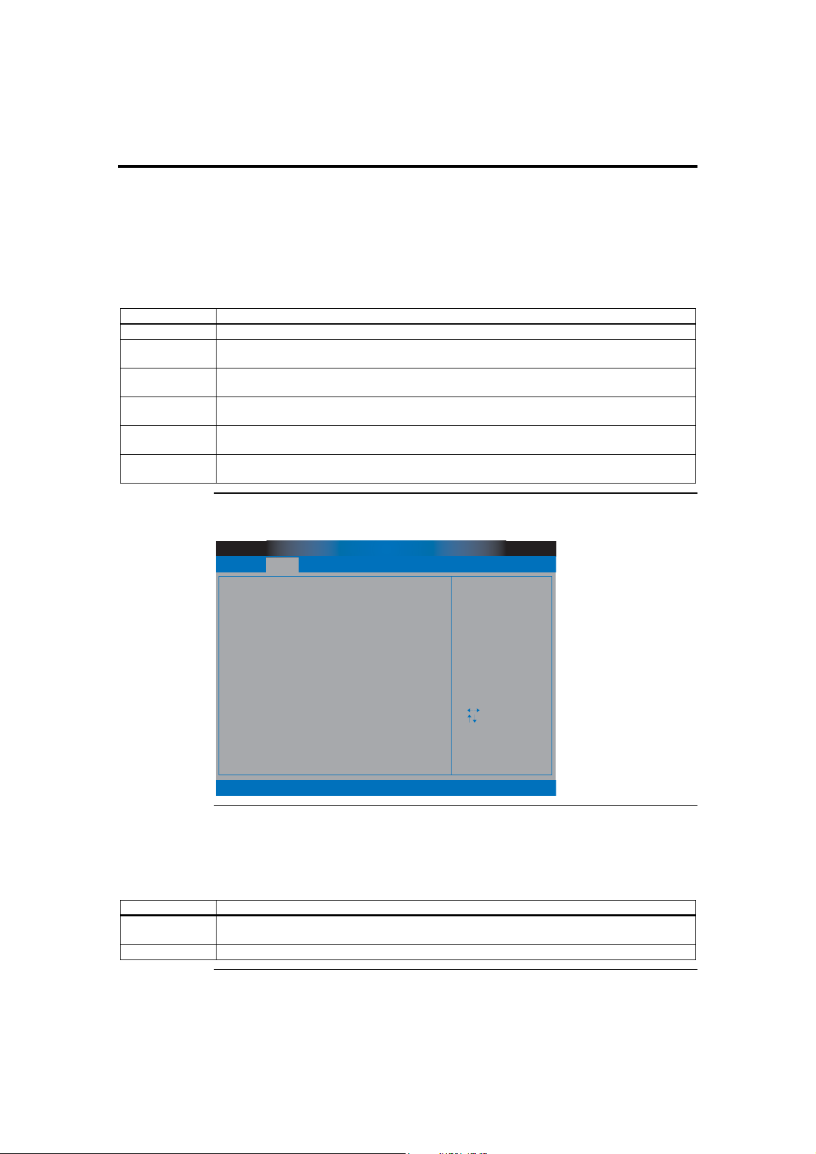
Section 2 Advanced Setup, Continued
Floppy A
Floppy B
Floppy disk drives are slowly being phased out of most systems. Since it is a relatively
slow and low storage medium, most do not find a need to install it. However, the
Olympus III motherboard still retains this legacy feature. It is especially useful when you
are trying to boot to DOS. The Optimal and Fail-Safe default setting is Disabled.
Option Description
Disabled Set this value to prevent the system from using the selected Floppy Drive location.
360 KB 5.25" Set this value to allow the system to address the selected Floppy Drive location as a 360 KB
5.25” floppy drive.
1.2 MB 5.25" Set this value to allow the system to address the selected Floppy Drive location as a 1.2 MB
5.25” floppy drive.
720 KB 3.5" Set this value to allow the system to address the selected Floppy Drive location as a 720 KB
3.5” floppy drive.
1.44 MB 3.5" Set this value to allow the system to address the selected Floppy Drive location as a 1.44 MB
3.5” floppy drive.
2.88 MB 3.5" Set this value to allow the system to address the selected Floppy Drive location as a 2.88 MB
3.5” floppy drive.
SuperIO Configuration
BIOS SETUP UTILITY
Main Advanced
SuperIO Configuration
Onboard Floppy Controller
Serial Port1 Address
Serial Port2 Address
Serial Port2 Mode
Parallel Port Address
Parallel Port Mode
ECP Mode DMA Channel
Parallel Port IRQ
PCIPnP Security
Boot
[Enabled]
[3F8/IRQ4]
[2F8/IRQ3]
[Normal]
[378]
[ECP]
[DMA3]
[IRQ7]
Chipset
ExitPower
AllowsBIOS to Enable
or Disable Floppy
Controller.
Select Screen
Select Item
+ -
Change Option
F1
General Help
F10
Save and Exit
ESC
Exit
v02.53 (C) Copyright 1985-2003, American Megatrends, Inc.
Onboard Floppy Controller
This field allows you to enable or disable the floppy disk drive controller on the Olympus
III motherboard. The default value for this setting is Enabled.
Option Description
Enabled Set this value to allow the system to use the onboard floppy disk drive controller. This is the
default value.
Disabled Set this value to prevent the system from using the onboard floppy disk drive controller.
American Megatrends, Inc., Olympus III User’s Guide (Series 875)
76
Cont’d
Page 87

Section 2 Advanced Setup, Continued
Serial Port1 Address
This option specifies the base I/O port address and Interrupt Request address of serial
port 1. The Optimal setting is 3F8/IRQ4. The Fail-Safe default setting is Disabled.
Option Description
Disabled This option prevents the serial port from accessing any system resources. It is not made
available.
3F8/IRQ4 This option allows the serial port to use 3F8 as its I/O port address and IRQ 4 for the interrupt
address. This is the default setting. The majority of serial port 1 or COM1 ports on computer
systems use IRQ4 and I/O Port 3F8 as the standard setting. The most common serial device
connected to this port is a mouse. If the system will not use a serial device, it is best to set this
port to Disabled.
3E8/IRQ4 This option allows the serial port to use 3E8 as its I/O port address and IRQ 4 for the interrupt
address. If the system will not use a serial device, it is best to set this port to Disabled.
2E8/IRQ3 This option allows the serial port to use 2E8 as its I/O port address and IRQ 3 for the interrupt
address. If the system will not use a serial device, it is best to set this port to Disabled.
Serial Port2 Address
This option specifies the base I/O port address and Interrupt Request address of serial
port 2. The Optimal setting is 2F8/IRQ3. The Fail-Safe setting is Disabled.
Option Description
Disabled This option prevents the serial port from accessing any system resources. It is not made
available.
2F8/IRQ3 This option allows the serial port to use 2F8 as its I/O port address and IRQ 3 for the interrupt
address. This is the default setting. The majority of serial port 2 or COM2 ports on computer
systems use IRQ3 and I/O Port 2F8 as the standard setting. If the system will not use a serial
device, it is best to set this port to Disabled.
3E8/IRQ4 This option allows the serial port to use 3E8 as its I/O port address and IRQ 4 for the interrupt
address. If the system will not use a serial device, it is best to set this port to Disabled.
2E8/IRQ3 This option allows the serial port to use 2E8 as its I/O port address and IRQ 3 for the interrupt
address. If the system will not use a serial device, it is best to set this port to Disabled.
Cont’d
Chapter Three : AMIBIOS Setup
77
Page 88

Section 2 Advanced Setup, Continued
Serial Port2 Mode
This option specifies the mode of the secondary onboard serial port I/O port. The
Optimal and Fail-Safe setting is Normal. When selecting settings other than Normal,
more choices become available under it. The options are all related to Infrared settings.
IrDA (Infrared Data Association)Error! Bookmark not defined. has about the same
transfer rate as that of a parallel port.
Option Description
Normal This option allows the motherboard to set the secondary onboard serial port to standard serial
port.
Sharp IR Sharp IR or ASK IR is a protocol developed by Sharp for use with its range of electronic
organizers. Sharp was a manufacturing partner for the Apple MessagePad and released a similar
model at the same time. Apple adopted the Sharp protocol, and included an application in the
Newton OS 1.x to connect via infrared to Sharp organizers and exchange data. This Infrared
protocol is widely used in Japan.
SIR SIR or Serial IR operates at higher rates. It is meant for long-range transmission where you need
more than a few characters to pass through.
Consumer Consumer IR can be used in long distance, but the transfer rate is very slow.
IR Duplex Mode
Option Description
Full Duplex This option allows the Infrared port to send and receive at the same time.
Half Duplex This option allows the Infrared port to send or receive information, then send or receive
IR Receiver Pin
Option Description
IRRX1 This option allows you to specify the IRRX1 pin to be used for receiving IR signals.
IRRX2 This option allows you to specify the IRRX2 pin to be used for receiving IR signals.
This option specifies the Infrared transfer used when any infrared option is enabled on
serial port 2. The Optimal and Fail-Safe settings hide this option completely. The default
setting is Full Duplex.
information after the infrared port is clear. It cannot perform both a send and receive at the
same time.
This option allows you to specify the receiver pin used to receive IR signals.
Cont’d
American Megatrends, Inc., Olympus III User’s Guide (Series 875)
78
Page 89

Section 2 Advanced Setup, Continued
Parallel Port Address
This option specifies the I/O address used by the parallel port. The Optimal setting is 378.
The Fail-Safe setting is Disabled.
Option Description
Disabled This option prevents the parallel port from accessing any system resources. It is not made
available.
378 This option allows the serial port to use 378 as its I/O port address. This is the default setting.
The majority of parallel ports on computer systems use IRQ7 and I/O Port 378H as the standard
setting.
278 This option allows the serial port to use 278 as its I/O port address.
3BC This option allows the serial port to use 3BC as its I/O port address.
Parallel Port Mode
Option Description
Normal This option allows the standard parallel port mode to be used. This is the default setting.
Bi-Directional This option allows data to be sent to and received from the parallel port.
EPP The parallel port can be used with devices that adhere to the Enhanced Parallel Port (EPP)
ECP The parallel port can be used with devices that adhere to the Extended Capabilities Port (ECP)
Parallel Port IRQ
Option Description
5 This option allows the serial port to use Interrupt 3.
7 This option allows the serial port to use Interrupt 7. This is the default setting. The majority of
This option specifies the parallel port mode. The Optimal setting is Normal. The FailSafe setting is Disabled.
specification. EPP uses the existing parallel port signals to provide asymmetric bi-directional
data transfer driven by the host device.
When EPP is selected, you can select the EPP Version as either 1.7 or 1.9.
specification. ECP uses the DMA protocol to achieve data transfer rates up to 2.5 Megabits per
second. ECP provides symmetric bi-directional communication.
When ECP is selected, you can change the value of the ECP Mode DMA Channel. It can be set
to 0, 1, or 3.
This option specifies the IRQ used by the parallel port. The Optimal and Fail-Safe
default setting is 7.
parallel ports on computer systems use IRQ7 and I/O Port 378H as the standard setting.
Cont’d
Chapter Three : AMIBIOS Setup
79
Page 90
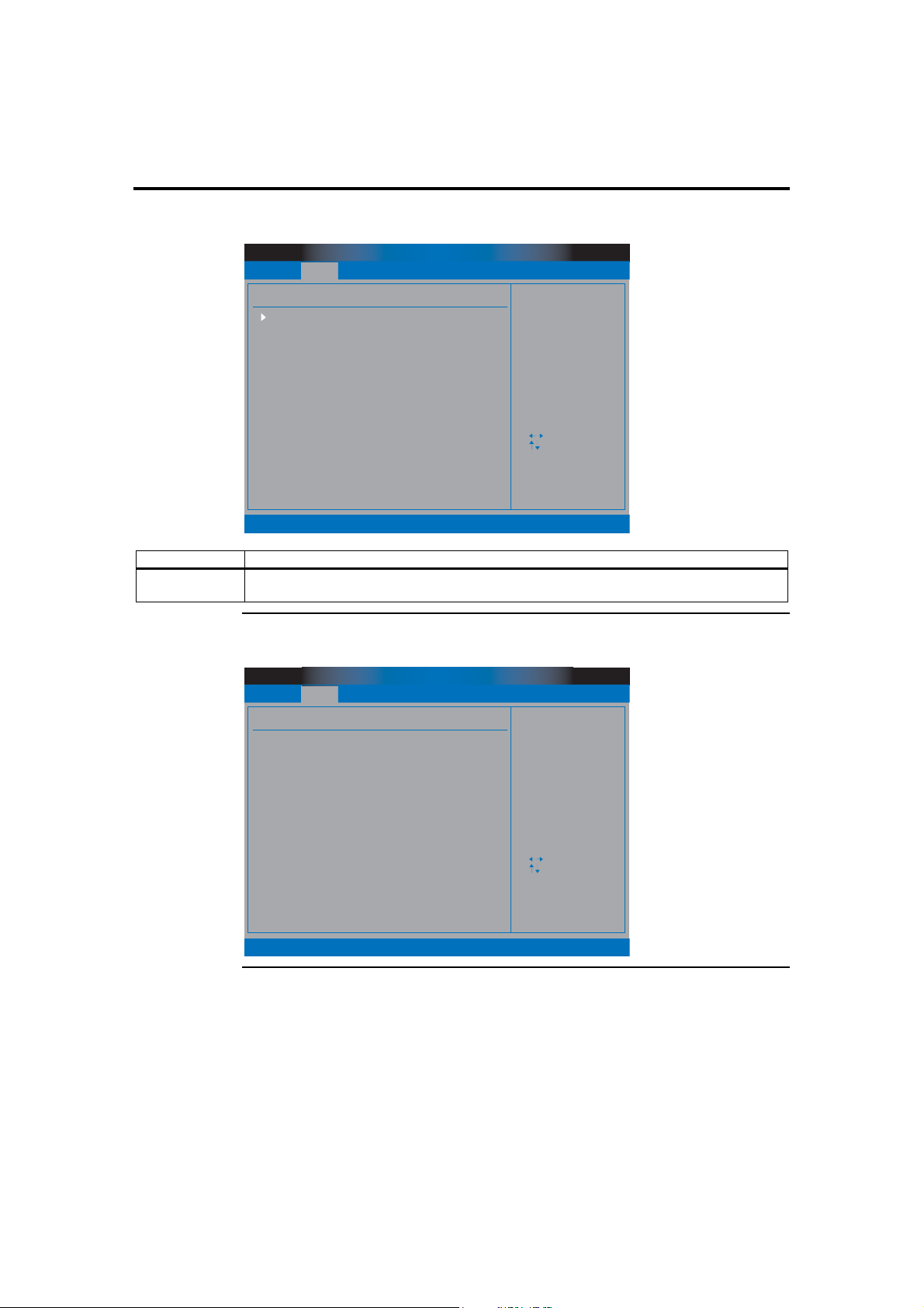
Section 2 Advanced Setup, Continued
ACPI Configuration
BIOS SETUP UTILITY
Main Advanced
ACPI Settings
Advanced ACPI Configuration
PCIPnP Security
Boot
Chipset
ExitPower
Advanced ACPI
Configuration settings
Use this section to
configure additional
ACPI options.
Select Screen
Select Item
Enter Go to Sub Screen
F1
General Help
F10
Save and Exit
ESC
Exit
v02.53 (C) Copyright 1985-2003, American Megatrends, Inc.
Option Description
Advanced ACPI
Configuration
This option allows you to enable or disable various ACPI (Advanced Configuration and Power
Interface) support.
Advanced ACPI Configuration
Main Advanced
Advanced ACPI Configuration
ACPI 2.0 Support
ACPI APIC support
APIC SCI IRQ
BIOS-->AML ACPI table
Headless mode
PCIPnP Security
v02.53 (C) Copyright 1985-2003, American Megatrends, Inc.
BIOS SETUP UTILITY
Boot
[No]
[Enabled]
[Disabled]
[Enabled]
[Disabled]
Chipset
ExitPower
Add additional tables
as per ACPI 2.0
specifications.
Select Screen
Select Item
+ -
Change Option
F1
General Help
F10
Save and Exit
ESC
Exit
Cont’d
American Megatrends, Inc., Olympus III User’s Guide (Series 875)
80
Page 91

Section 2 Advanced Setup, Continued
ACPI 2.0 Support
This option allows you to enable or disable ACPI (Advanced Configuration and Power
Interface) 2.0 support.
Option Description
No This option turns off ACPI 2.0 support and is the default setting.
Yes This option turns on ACPI 2.0 support.
ACPI APIC Support
Option Description
Disabled This option turns off ACPI APIC support.
Enabled This option turns on ACPI APIC support and is the default setting.
APIC SCI IRQ
Option Description
Disabled This option turns off APIC SCI IRQ support and is the default setting.
Enabled This option turns on APIC SCI IRQ support.
BIOS-->AML ACPI Table
Option Description
Disabled This option turns off the BIOS--> AML ACPI table function.
Enabled This option turns on the BIOS--> AML ACPI table function and is the default setting.
Headless Mode
Option Description
Disabled This option turns off headless operation mode through ACPI and is the default setting.
Enabled This option turns on headless operation mode through ACPI.
This option allows you to enable or disable ACPI APIC (Advanced Programmable
Interrupt Controller) support.
This option allows you to enable or disable APIC SCI IRQ.
This option allows you to enable or disable the BIOS-->AML ACPI table function.
This option allows you to enable or disable headless operation mode through ACPI.
Cont’d
Chapter Three : AMIBIOS Setup
81
Page 92
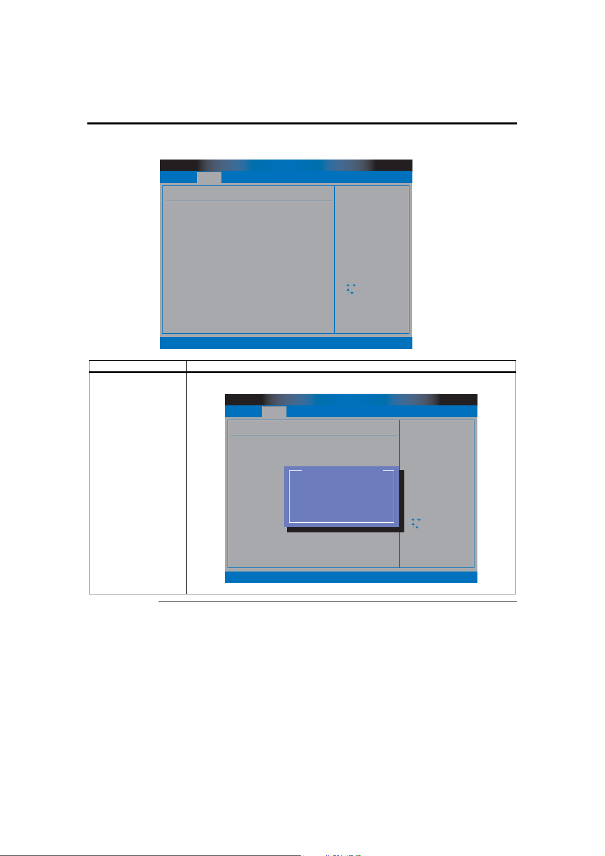
Section 2 Advanced Setup, Continued
DMI Event Logging
BIOS SETUP UTILITY
Main Advanced
Event Logging details
View Event Log
Mark all events as read
Clear Event Log
Event Log Statistics
PCIPnP Security
Boot
Chipset
ExitPower
View all unread events
on the Event Log.
Select Screen
Select Item
Enter Go to Sub Screen
F1
General Help
F10
Save and Exit
ESC
Exit
v02.53 (C) Copyright 1985-2003, American Megatrends, Inc.
Field Description
View Event Logging This option allows you to read all comments stored in CMOS.
BIOS SETUP UTILITY
Main Advanced
Event Logging details
View Event Log
Mark all events as read
Clear Event Log
Event Log Statistics
PCIPnP Security
01/10/03 00:07:15
Keyboard not functional
01/09/03 00:54:06
Keyboard not functional
01/09/03 23:54:06
CMOS checksum error
v02.53 (C) Copyright 1985-2003, American Megatrends, Inc.
Boot
View Event Log
Chipset
ExitPower
View all unread events
on the Event Log.
Select Screen
Select Item
Enter Go to Sub Screen
F1
General Help
F10
Save and Exit
ESC
Exit
Cont’d
American Megatrends, Inc., Olympus III User’s Guide (Series 875)
82
Page 93
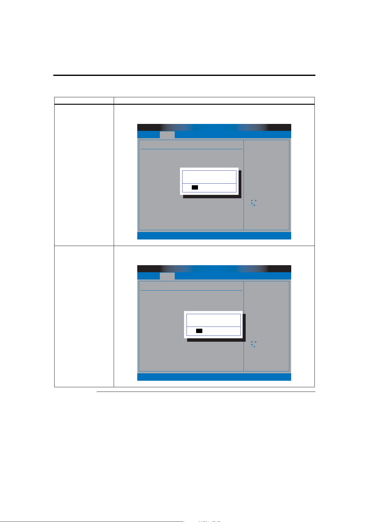
Section 2 Advanced Setup, Continued
DMI Event Logging, Continued
Field Description
Mark All Events As
Read
This option allows you to designate that all comments in the CMOS have been read even
though they have not.
Main Advanced
Event Logging details
View Event Log
Mark all events as read
Clear Event Log
Event Log Statistics
PCIPnP Security
BIOS SETUP UTILITY
Boot
Mark all events as read now ?
[Ok] [Cancel]
Chipset
ExitPower
Mark all unread events
as read.
Select Screen
Select Item
Enter
Go to Sub Screen
F1
General Help
F10
Save and Exit
ESC
Exit
v02.53 (C) Copyright 1985-2003, American Megatrends, Inc.
Clear Event Logs This option allows you to delete all comments stored in your CMOS. Press the <ENTER>
key to delete all events stored in CMOS.
BIOS SETUP UTILITY
Main Advanced
Event Logging details
View Event Log
Mark all events as read
Clear Event Log
Event Log Statistics
PCIPnP Security
v02.53 (C) Copyright 1985-2003, American Megatrends, Inc.
Boot
Clear Event Log now ?
[Ok] [Cancel]
Chipset
ExitPower
Discard all events
in the Event Log.
Select Screen
Select Item
Enter
Go to Sub Screen
F1
General Help
F10
Save and Exit
ESC
Exit
Cont’d
Chapter Three : AMIBIOS Setup
83
Page 94
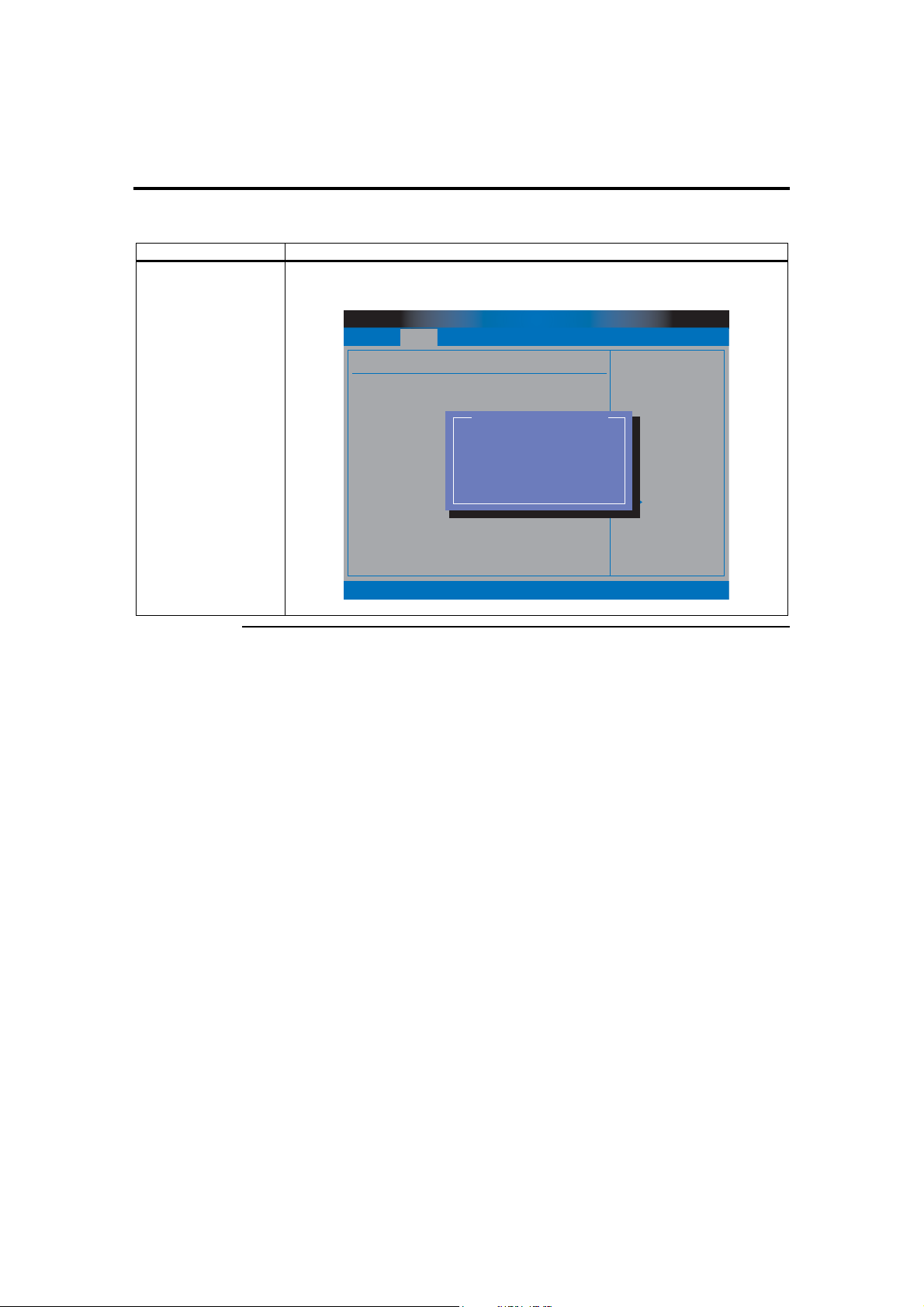
Section 2 Advanced Setup, Continued
DMI Event Logging, Continued
Field Description
Event Log Statistics This option allows you to view the event log statistics such as Total Size, Free Size, and
Unread Events.
BIOS SETUP UTILITY
Main Advanced
Event Logging details
View Event Log
Mark all events as read
Clear Event Log
Event Log Statistics
PCIPnP Security
Boot
Event Log Statistics
Total size (in events)
6.3
Free size (in events)
61
Unread events
02
Chipset
ExitPower
View details on the
count of total unread
events.
Other stats include
size occupied and
free. (in terms
ent units)
Select Screen
Select Item
Enter
Go to Sub Screen
F1
General Help
F10
Save and Exit
ESC
Exit
v02.53 (C) Copyright 1985-2003, American Megatrends, Inc.
Cont’d
American Megatrends, Inc., Olympus III User’s Guide (Series 875)
84
Page 95
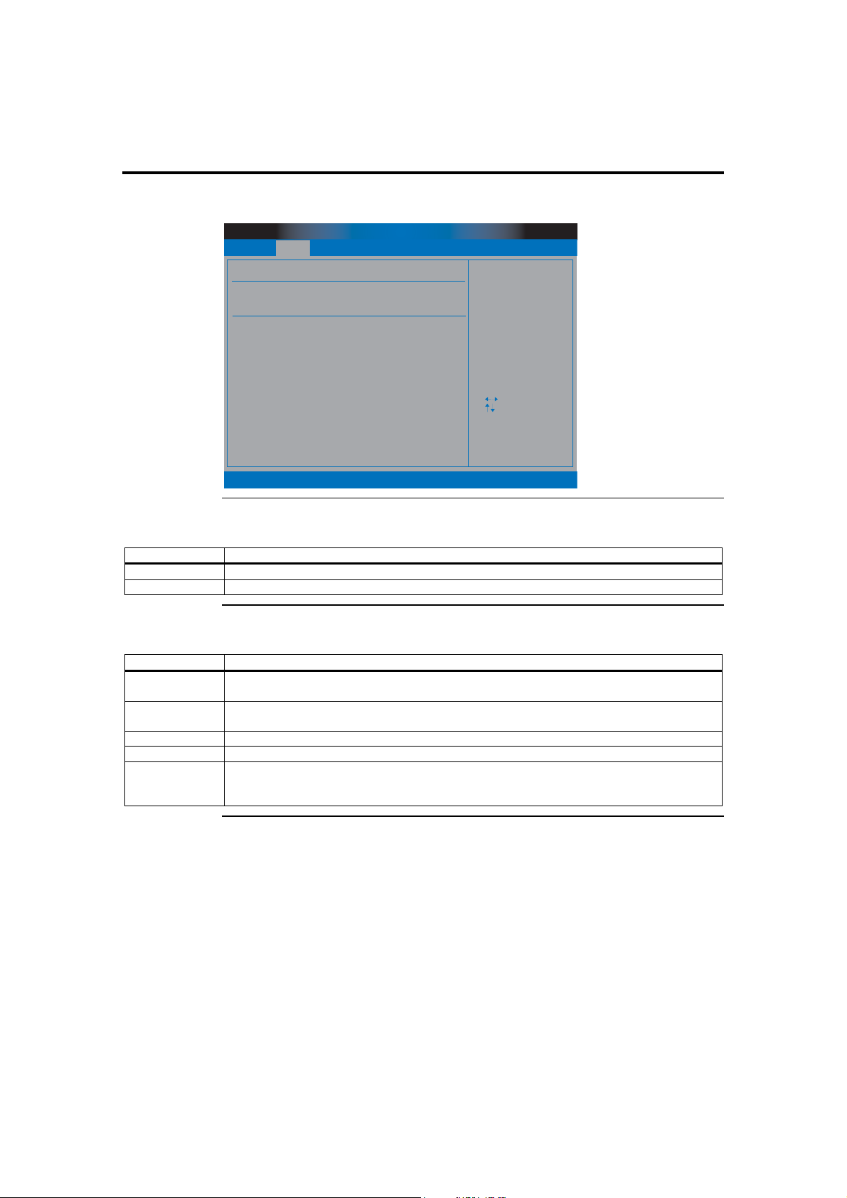
Section 2 Advanced Setup, Continued
Hardware Health Configuration
BIOS SETUP UTILITY
Main Advanced
Hardware Health Configuratiion
H/W Health Function [Disabled]
Hardware Health Event Monitoring
PCIPnP Security
Boot
Chipset
ExitPower
Enables Hardware
Health Monitoring
Device.
Select Screen
Select Item
+ -
Change Option
F1
General Help
F10
Save and Exit
ESC
Exit
v02.53 (C) Copyright 1985-2003, American Megatrends, Inc.
HW Health Function
Option Description
Disabled This option turns off hardware health monitoring
Enabled This option turns on hardware health monitoring and is the default setting.
Hardware Health Event Monitoring
Field Description
System
Temperature
CPU
Temperature
Fan1/2/3 Speed Displays the current speed of CPU cooling fan at JP2 and Auxiliary Fans at JP5 and JP6.
CPU Core Displays the current CPU core actual voltage value.
1.5V/3.3V/+12V
/+5.00V/5VSB/
Battery
Displays the current internal system ambient temperature.
Displays the current CPU internal temperature.
Displays the current voltage against the 1.5V/3.3V/+12V/+5V/5VSB/Battery power supply.
Cont’d
Chapter Three : AMIBIOS Setup
85
Page 96
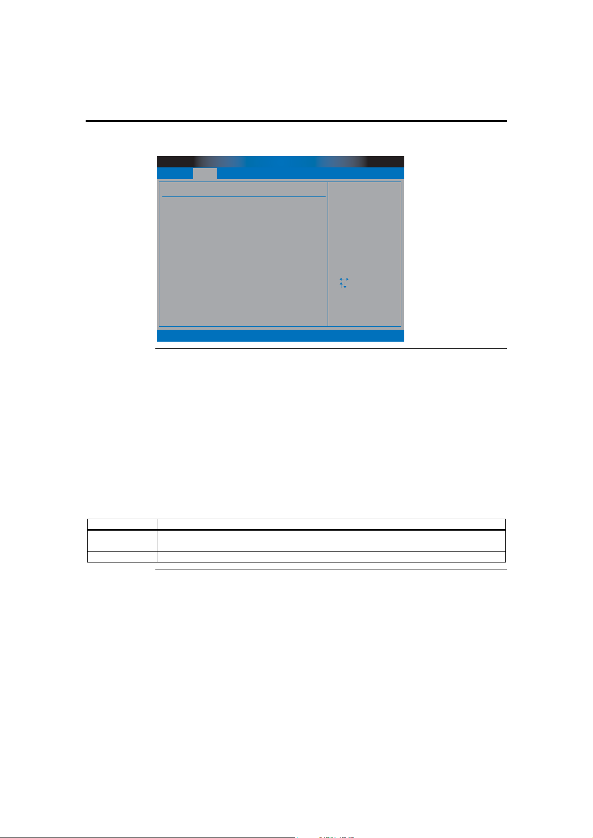
Section 2 Advanced Setup, Continued
MPS Configuration
BIOS SETUP UTILITY
Main Advanced
MPS Configuratiion
MPS Revision [1.4]
PCIPnP Security
Boot
Chipset
MPS Revision
selection
Select Screen
Select Item
+ -
Change Option
F1
General Help
F10
Save and Exit
ESC
Exit
ExitPower
v02.53 (C) Copyright 1985-2003, American Megatrends, Inc.
MPS Revision
The AMIBIOS Setup allows you to select whether to use Multi-Processor Specification
(MPS) 1.1 or 1.4. The MPS is a specification by which PC manufacturers design and
build Intel architecture (IA) systems with two or more processors.
MPS version 1.4 added extended configuration tables to improve support for multiple
PCI bus configurations and improve future expandability. Most newer versions of server
operating systems support MPS 1.4 and, as such, you should not change the BIOS Setup
default of 1.4 to 1.1 if your operating system supports the 1.4 version.
Check with the vendor of your operating system to find out which version to use if you
are unsure. Some operating systems may require version 1.1 for compatibility reasons.
Option Description
1.4 This option allows the BIOS to use MultiProcessor Specification version 1.4. This is the default
setting.
1.1 This option allows the BIOS to use MultiProcessor Specification version 1.1.
Cont’d
American Megatrends, Inc., Olympus III User’s Guide (Series 875)
86
Page 97
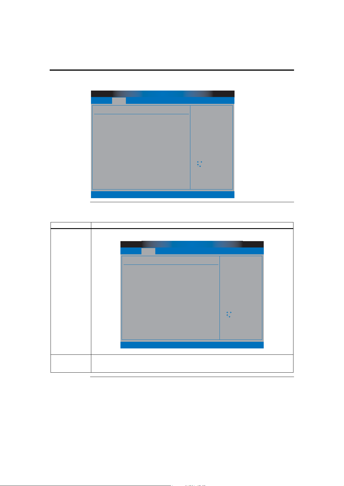
Section 2 Advanced Setup, Continued
Remote Access Configuration
BIOS SETUP UTILITY
Main Advanced
Configure Remote Access type and parameters
Remote Access
Serial Port Number
Serial Port Mode
Flow Control
Redirection After BIOS POST
Terminal Type
VT-UTF8 Type Combo Key Support
PCIPnP Security
Boot
[Enabled]
[COM1]
[XXXXX.X.X.X]
[None]
[Disabled]
[ANSI]
[Disabled]
Chipset
ExitPower
Select Remote Access
type.
Select Screen
Select Item
+ -
Change Option
F1
General Help
F10
Save and Exit
ESC
Exit
v02.53 (C) Copyright 1985-2003, American Megatrends, Inc.
Remote Access
Option Description
Disabled This option turns off remote access support in the BIOS.
BIOS SETUP UTILITY
Main Advanced
Configure Remote Access type and parameters
Remote Access
PCIPnP Security
v02.53 (C) Copyright 1985-2003, American Megatrends, Inc.
Enabled This option turns on remote access support in the BIOS and is the default setting. The remote
access feature requires the use of the serial port connector located at the rear of the Olympus III
motherboard or serial port 2 located at J20.
Boot
[Disabled]
Chipset
ExitPower
Select Remote Access
type.
Select Screen
Select Item
+ -
Change Option
F1
General Help
F10
Save and Exit
ESC
Exit
Cont’d
Chapter Three : AMIBIOS Setup
87
Page 98

Section 2 Advanced Setup, Continued
Serial Port Number
Option Description
COM1 This setting allows you to use the serial port connector located at the rear of the Olympus III
motherboard. This is the default value.
COM2 This setting allows you to use the internal serial port connector located at J20 on the Olympus
III motherboard.
Serial Port Mode
You can use any mode you want. Just keep in mind that the bits per second, data bits,
parity, and stop bits must match your terminal setting.
Option Description
115200 8,n,1 This value allows the serial port to transfer data at 115200 bits per second using eight data bits,
no parity bit, and one stop bit.
57600 8,n,1 This value allows the serial port to transfer data at 57600 bits per second using eight data bits,
no parity bit, and one stop bit.
19200 8,n,1 This value allows the serial port to transfer data at 19200 bits per second using eight data bits,
no parity bit, and one stop bit. This is the default value.
Flow Control
Option Description
None This value turns off data flow control (handshaking). Flow control is not used. This is the
default value.
Software This value allows software handshaking to be used to control data flow.
Hardware This value allows hardware handshaking to be used to control data flow.
Redirection After BIOS POST
Option Description
Disabled This value turns off redirection after POST. This is the default value.
Boot Loader This value turns on redirection during POST and during the time when the operating system is
Always This value allows redirection to be on at all times. Some operating systems may not work if this
Terminal Type
Option Description
ANSI Use this value if your target terminal uses a standard US (United States) ANSI keyboard. This is
VT-UTF8 Use this value if your target terminal uses VT-UTF8 combination keys.
booting.
value is used.
the default value.
Cont’d
American Megatrends, Inc., Olympus III User’s Guide (Series 875)
88
Page 99
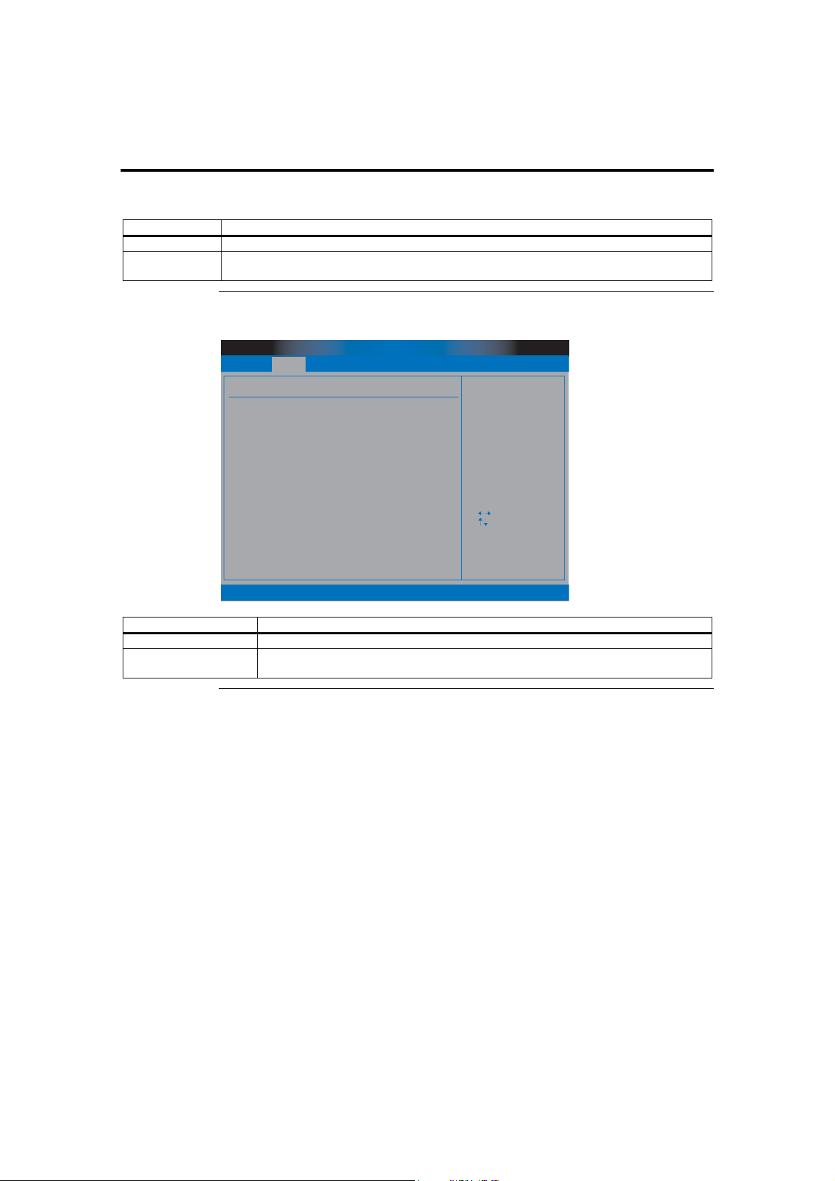
Section 2 Advanced Setup, Continued
VT-UTF8 Type Combo Key Support
Option Description
Disabled This option turns off VT-UTF8 combination key support for ANSI/VT100 terminals.
Enabled This option turns on VT-UTF8 combination key support for ANSI/VT100 terminals. This is the
default value.
USB Configuration
BIOS SETUP UTILITY
Main Advanced
USB Configuration
Module Version - 2.23.0-7.4
USB Devices Enabled :
None
PCIPnP Security
Boot
Chipset
ExitPower
Enables USB host
controllers.
USB Function
Legacy USB Support
USB 2.0 Controller
USB 2.0 Controller Mode
v02.53 (C) Copyright 1985-2003, American Megatrends, Inc.
[8 USB Ports]
[Enabled]
[Enabled]
[HiSpeed]
+ F1
F10
ESC
Select Screen
Select Item
Change Option
General Help
Save and Exit
Exit
Field Description
Module Version This field displays the version of the USB module.
USB Devices Enabled This field lists all USB devices that are attached and functioning properly on the Olympus
III motherboard.
Cont’d
Chapter Three : AMIBIOS Setup
89
Page 100
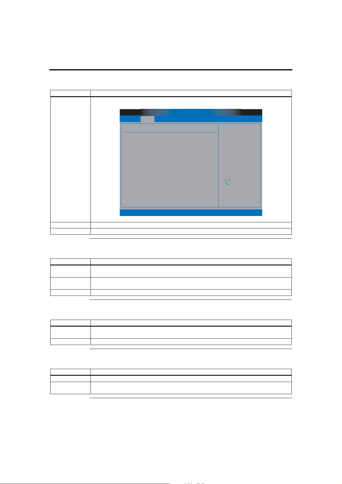
Section 2 Advanced Setup, Continued
USB Function
Option Description
Disabled Set this value to prevent the system from using any of the onboard USB ports.
BIOS SETUP UTILITY
Main Advanced
USB Configuration
Module Version - 2.23.0-7.4
USB Devices Enabled :
None
PCIPnP Security
Boot
Chipset
Enables USB host
controllers.
ExitPower
USB Function
v02.53 (C) Copyright 1985-2003, American Megatrends, Inc.
[Disabled]
+ F1
F10
ESC
Select Screen
Select Item
Change Option
General Help
Save and Exit
Exit
2 USB Ports Set this value to allow the system to address up to two USB ports.
4 USB Ports Set this value to allow the system to address up to four USB ports. This is the default value.
Legacy USB Support
Option Description
Enabled Set this value to allow the system to use legacy USB devices such as a USB keyboard and a
USB mouse. This is the default value.
Disabled Set this value to prevent the system from using legacy USB devices such as a USB keyboard
and a USB mouse.
Auto Set this value to allow the BIOS to automatically detect the correct settings.
USB 2.0 Controller
Option Description
Enabled Set this value to allow the system to use the onboard USB 2.0 controller. This is the default
value.
Disabled Set this value to prevent the system from using the onboard USB 2.0 controller.
USB 2.0 Controller Mode
Option Description
FullSpeed Set this value to force the BIOS to use the onboard USB 2.0 controller at the USB 1.1 speeds.
HiSpeed Set this value to force the BIOS to use the onboard USB 2.0 controller at full USB 2.0 speeds.
This is the default value.
American Megatrends, Inc., Olympus III User’s Guide (Series 875)
90
 Loading...