

Page 1

Megaplex Quad Pentium II
Xeon PCI ISA System
Guide
MAN-770
1/12/99
Page 2

© Copyright 1999 American Megatrends, Inc.
All rights reserved.
American Megatrends, Inc.
6145F Northbelt Parkway
Norcross, GA 30071
Copyright Notice
This publication contains proprietary information which is protected by copyright. No part of
this publication can be reproduced, transcribed, stored in a retrieval system, translated into any
language or computer language, or transmitted in any form whatsoever without the prior written
consent of the publisher, American Megatrends, Inc. American Megatrends, Inc. acknowledges
the following trademarks:
Limited Warranty The buyer agrees if this product proves to be defective, that American
Limitations of Liability American Megatrends, Inc. shall in no event be held liable for any
Trademarks
Intel, Pentium, and Xeon are registered trademarks of Intel Corporation.
MS-DOS, Microsoft Word, and Microsoft are registered trademarks of Microsoft Corporation. Microsoft
Windows, Windows 95, and Windows NT are trademarks of Microsoft Corporation.
AMD is a registered trademark of Advanced Micro Devices, Inc.
National Semiconductor is a registered trademark of National Semiconductor Corporation.
SMC is a registered trademark of Standard Microsystems Corporation.
IBM, AT, VGA, PS/2, OS/2, and EGA are registered trademarks of International Business Machines
Corporation. XT and CGA are trademarks of International Business Machines Corporation.
SCO, UnixWare, and Unix are registered trademarks of The Santa Cruz Operation, Inc.
All other brand and product names are trademarks or registered trademarks of their respective companies.
Megatrends is only obligated to repair or replace this product at American
Megatrends’ discretion according to the terms and conditions of the
warranty registration card that accompanies this product. American
Megatrends shall not be liable in tort or contract for any loss or damage,
direct, incidental or consequential resulting from the use of this product.
Please see the Warranty Registration Card shipped with this product for
full warranty details.
loss, expenses, or damages of any kind whatsoever, whether direct,
indirect, incidental, or consequential (whether arising from the design or
use of this product or the support materials provided with the product).
No action or proceeding against American Megatrends may be
commenced more than two years after the delivery of product to Licensee
of Licensed Software.
Licensee agrees to defend and indemnify American Megatrends from any
and all claims, suits, and liabilities (including attorney’s fees) arising out
of or resulting from any actual or alleged act or omission on the part of
Licensee, its authorized third parties, employees, or agents, in connection
with the distribution of Licensed Software to end-users, including,
without limitation, claims, suits, and liability for bodily or other injuries
to end-users resulting from use of Licensee’s product not caused solely by
faults in Licensed Software as provided by American Megatrends to
Licensee.
Revision History
9/4/98 Initial release.
9/23/98 Released revised draft.
11/02/98 Added AMI Server Manager information.
1/12/99 Revised AMI Server Manager chapter.
Megaplex Quad Pentium II Xeon PCI ISA System Guide
ii
Page 3

Table of Contents
1 Hardware Installation...............................1
Features .........................................................................1
Megaplex Dimensions....................................................4
Installation Steps............................................................8
Avoid Static Electricity...................................................8
Step 1 Unpack the Boards...............................................9
Step 2 Configure CPU Board ........................................10
Step 3 Configure I/O Board..........................................17
Step 4 Install Memory ..................................................18
Step 5 Install Motherboard ...........................................25
Step 6 Connect Power Supply.......................................27
Step 7 Attach Connectors .............................................30
Step 8 Test and Configure ............................................44
2 AMIBIOS® Setup.....................................47
AMIBIOS Setup Menu .................................................48
Section 1 Standard Setup.....................................................49
Section 2 Advanced CMOS Setup.......................................54
Section 3 Power Management Setup ....................................59
Section 4 PCI/PnP Setup.....................................................63
Section 5 Peripheral Setup..................................................69
Section 6 Other Setup Options.............................................72
Auto-Detect Hard Disks ...............................................72
AMIBIOS Password Support ........................................72
Change User Password.................................................73
Change Supervisor Password ........................................73
Change Language Settings............................................73
Auto Configuration with Optimal Settings .................... 74
Auto Configuration with FailSafe Settings.................... 74
Save Settings and Exit.................................................. 74
Exit Without Saving..................................................... 74
3 Programming the Flash ROM................75
Bootblock Code Checkpoint Codes............................... 79
4 AMI Server Manager Overview and Setup81
AMI Server Manager Overview....................................82
Quick Start ...................................................................83
Installing AMI Server Manager ....................................88
AMI Server Manager Setup.......................................... 88
Selecting a Server.........................................................90
Warnings and Alerts .....................................................91
Using the LCD.............................................................92
Preface
iii
Page 4

Table of Contents, Continued
5 AMI Server Manager Screens.................93
Basic Screen Information .............................................93
Main Screen.................................................................96
System Inventory..........................................................98
Health Information.......................................................99
Chassis Status ............................................................104
Health Graph.............................................................. 107
Performance Graph ....................................................110
BIOS Event Display................................................... 111
Health Events .............................................................112
6 AMI Server Manager Icons and Menus113
AMI Server Manager Toolbar Icons............................113
AMI Server Manager Top Frame Icons .......................118
AMI Server Manager Menus ......................................121
7 Flashing the LCD ROM ........................127
Overview ...................................................................127
LCD ROM Panel........................................................ 128
Tools..........................................................................130
Flashing the LCD ROM..............................................130
Index.................................................................132
Megaplex Quad Pentium II Xeon PCI ISA System Guide
iv
Page 5

Preface
To the OEM Thank you for purchasing the high performance American
Megatrends Megaplex Quad Pentium II Xeon PCI ISA
System. This product is a state-of-the-art set of a memory
card and a motherboard that includes the famous
AMIBIOS.
This manual was written for the OEM to assist in the
proper installation and operation of this product. This
manual describes the specifications and features of the
Quad Pentium II Xeon system. It explains how to assemble
a system based on the Quad Pentium II Xeon system and
how to use the AMIBIOS that is specifically designed for
this system. In addition, it describes AMI Server Manager
Version 1.00, which is used to manage several servers
simultaneously from one location.
This manual is not meant to be read by the computer
owner who purchases a computer with this system. It is
assumed that you, the computer manufacturer, will use this
manual as a sourcebook of information, and that part of
this manual will be included in the computer owner’s
manual.
Cont’d
Preface
v
Page 6

Preface, Continued
Technical Support If you need help installing, configuring, or running this
software, call American Megatrends technical support at
770-246-8600. You can also send questions to tech support
at:
American Megatrends BBS The American Megatrends BBS permits you to
access technical information about American Megatrends
motherboard, peripheral, and BIOS products. Product
Engineering Change Notices, Tech Tips, and technical
documentation are available on the BBS. Some parts of the
BBS are not accessible to all callers. Call American
Megatrends Technical Support at 770-246-8600 to find out
how to access the BBS. The BBS requires no parity, eight
data bits, and one stop bit. The BBS phone number is 770246-8780.
Web Site We invite you to access the American Megatrends world
wide web site at http://www.ami.com.
Cont’d
Megaplex Quad Pentium II Xeon PCI ISA System Guide
vi
Page 7

Preface, Continued
Packing List You should have received the following:
• a Series 769 CPU board,
• a Series 770 I/O board,
• three Series 776 CPU termination cards,
• a Series 777 memory expansion card (if ordered),
• a Series 778 memory termination card (if 777 is not
ordered),
• four retention units, which include four base
mechanisms, four top covers, eight ears, four pegs,
and sixteen screws with nuts,
• four heatsinks for Pentium II Xeon CPUs with sixteen
mounting screws,
• floppy diskettes that contain the American Megatrends
BIOS upgrade for Server Manager software,
• Server Manager CD, with ATI264GT-B VGA
Drivers,
• the Megaplex Quad Pentium II Xeon PCI ISA System Guide,
• the Megaplex Server Chassis Guide, and
• the warranty card.
Static Electricity The Megaplex Quad Pentium II Xeon motherboard and
memory card can easily be damaged by static electricity.
Make sure you take appropriate precautions against static
electric discharge:
• wear a properly-grounded wristband while handling the
Megaplex system or any other electrical component;
• touch a grounded anti-static surface or a grounded
metal fixture before handling the Megaplex system,
• handle system components by the mounting bracket, if
possible.
Cont'd
Preface
vii
Page 8

Preface, Continued
Batteries
Caution
Make sure you dispose of used batteries according to the battery
manufacturer’s instructions. Improper use of batteries can cause
an explosion. Make sure you follow the battery manufacturer’s
instructions about using the battery. Replace used batteries with
the same type of battery or an equivalent recommended by the
battery manufacturer.
Attention
Il y a danger d'explosion s'il y a remplacement de la batterie.
Remplacer uniquement avec une batterie du même type ou d'un
équivalent recommandé par la constructeur. Mettre au rebut les
batteries usagées conformément aux instructions du fabricant.
Cont’d
Megaplex Quad Pentium II Xeon PCI ISA System Guide
viii
Page 9

Preface, Continued
Disclaimer This manual describes the installation and operation of the
American Megatrends Megaplex Quad Pentium II Xeon PCI ISA
system. Although efforts have been made to assure the accuracy
of the information contained here, American Megatrends
expressly disclaims liability for any error in this information, and
for damages, whether direct, indirect, special, exemplary,
consequential or otherwise, that may result from such error,
including but not limited to the loss of profits resulting from the
use or misuse of the manual or information contained therein
(even if American Megatrends has been advised of the possibility
of such damages). Any questions or comments regarding this
document or its contents should be addressed to American
Megatrends at the address shown on the cover.
American Megatrends provides this publication “as is” without
warranty of any kind, either expressed or implied, including, but
not limited to, the implied warranties of merchantability or fitness
for a specific purpose.
Some states do not allow disclaimer of express or implied
warranties or the limitation or exclusion of liability for indirect,
special, exemplary, incidental or consequential damages in
certain transactions; therefore, this statement may not apply to
you. Also, you may have other rights which vary from
jurisdiction to jurisdiction.
This publication could include technical inaccuracies or
typographical errors. Changes are periodically made to the
information herein; these changes will be incorporated in new
editions of the publication. American Megatrends may make
improvements and/or revisions in the product(s) and/or the
program(s) described in this publication at any time.
Requests for technical information about American Megatrends
products should be made to your American Megatrends
authorized reseller or marketing representative.
Preface
ix
Page 10

Megaplex Quad Pentium II Xeon PCI ISA System Guide
x
Page 11

1 Hardware Installation
Features
The American Megatrends Megaplex Quad Pentium II
Xeon ISA PCI system supports one to four Intel® Pentium
II Xeon CPUs operating at 400/450 MHz.
Components The Megaplex consists of the following components:
• a Series 769 CPU board,
• a Series 770 I/O board,
• three (3) Series 776 CPU termination cards,
• a Series 777 memory expansion card (if ordered), and
• a Series 778 memory termination card (if the 777 card
is not installed).
CPUs The four Pentium II Xeon CPU sockets are mounted on the
Series 769 CPU board.
System Memory The Megaplex system supports up to 8 GB of system
memory, of which 4 GB is on the CPU board, and 4 GB on
the memory expansion card. This system supports fourway interleaved memory operation with ABP and C2C for
maximum performance. The system supports 168-pin
buffered EDO DIMMs (FPM is not supported.) The
system memory supports ECC (Error Checking and
Correction).
Note: DRAM system memory is measured in megabits.
For example, a DIMM that is 4 M x 72 has four (4)
megabits of memory. See page 21 for more information
about DRAM specifications.
Cont’d
Chapter 1 Hardware Installation
1
Page 12

Features, Continued
Cache Memory The Megaplex system provides 1 MB of cache memory
internal to each Pentium II Xeon CPU.
ISA Expansion The Megaplex motherboard includes two ISA expansion
slots. Both expansion slots can handle full-length ISA
adapter cards.
PCI Local Bus The Megaplex motherboard has twelve PCI expansion
slots, eight 32-bit and four 64-bit. The 32-bit slots are on
two peer PCI buses provided by the first PXB (PCI
Expander Bridge), while the 64-bit slots are on another
independent PCI bus provided by the second PXB. All
PCI slots are bus master slots. All PCI expansion slots can
handle full-length PCI adapter cards.
Integrated I/O The Megaplex motherboard provides the following
integrated I/O:
• one bidirectional parallel port that operates in Normal,
EPP, or ECP mode,
• a VGA connector,
• two serial port connectors with 16550A UARTs,
• one floppy drive controller with support for 360 KB,
720 KB, 1.2 MB, 1.44 MB, and 2.88 MB floppy
drives,
• dual channel Ultra DMA IDE support,
• two USB port connectors, and
• a standard 2-in-1 connector assembly for PS/2
keyboard and PS/2 mouse.
Cont’d
Megaplex Quad Pentium II Xeon PCI ISA System Guide
2
Page 13

Features, Continued
Onboard VGA The Megaplex includes an onboard ATI 264GT-B PCI
VGA controller with 2 MB of SGRAM. Video drivers for
Windows NT are provided. You can download video
drivers for all other operating systems from the ATI BBS
at 905-764-9404. Make sure you load the ATI 264GT-B
drivers from the diskette provided. Windows 95 auto
detection tries to load the ATI Mach 64 drivers, which will
not function properly.
AMIBIOS AMIBIOS includes a PCI BIOS with AMIBIOS® Setup in
flash ROM. Features include:
• automatic CPU detection,
• Plug and Play NVRAM and PCI-PCI bridge support,
• DMI support,
• ATAPI support for IDE CD-ROM drives,
• complete SM1/ACPI support,
• ability to boot from a CD-ROM drive,
• flex boot/silent boot support,
• USB support,
• ZIP drive support,
• GPNVRAM support,
• APM 1.2 support,
• complies with the Intel NSP specification,
• automatically detects IDE drive parameters,
• supports Enhanced IDE, including four IDE drives,
• supports ATA IDE mode programming,
• provides LBA and Block Mode support,
• provides boot sector virus protection,
• automatically detects and configures system memory,
cache memory, and the CPU type,
• automatically configures PCI devices, and
• complies with the Plug and Play Version 1.0A BIOS
specification.
PCI Bus Speed The Megaplex system conforms to the PCI Version 2.1
specification. The PCI slots are automatically configured
by the AMIBIOS. The PCI slots operate synchronously
with the CPU clock at 33 MHz.
Chapter 1 Hardware Installation
3
Page 14
Megaplex Dimensions
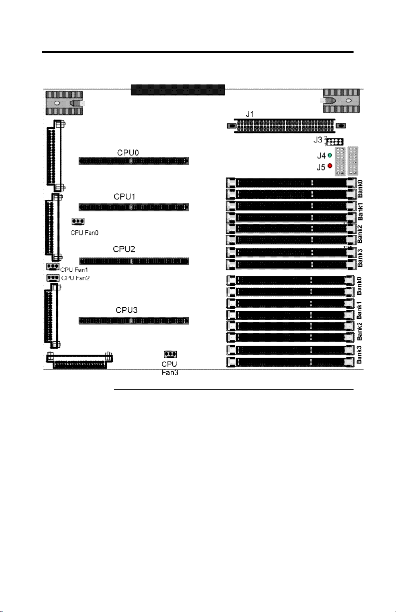
Series 769 CPU Board The Series 769 CPU board is 16” by 14”.
Megaplex Quad Pentium II Xeon PCI ISA System Guide
4
Cont’d
Page 15
Megaplex Dimensions, Continued
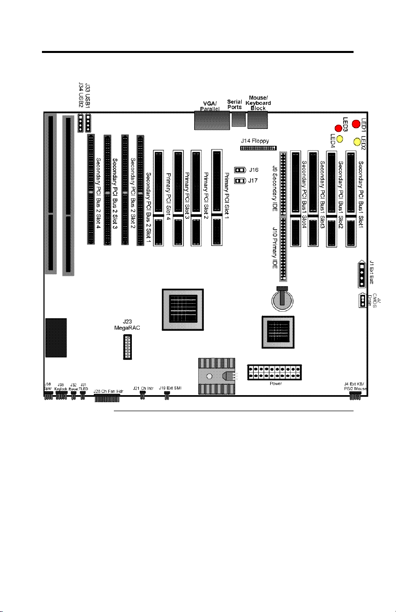
Series 770 I/O Board The Series 770 I/O board is 16” by 13.8”.
Cont’d
Chapter 1 Hardware Installation
5
Page 16
Megaplex Dimensions, Continued
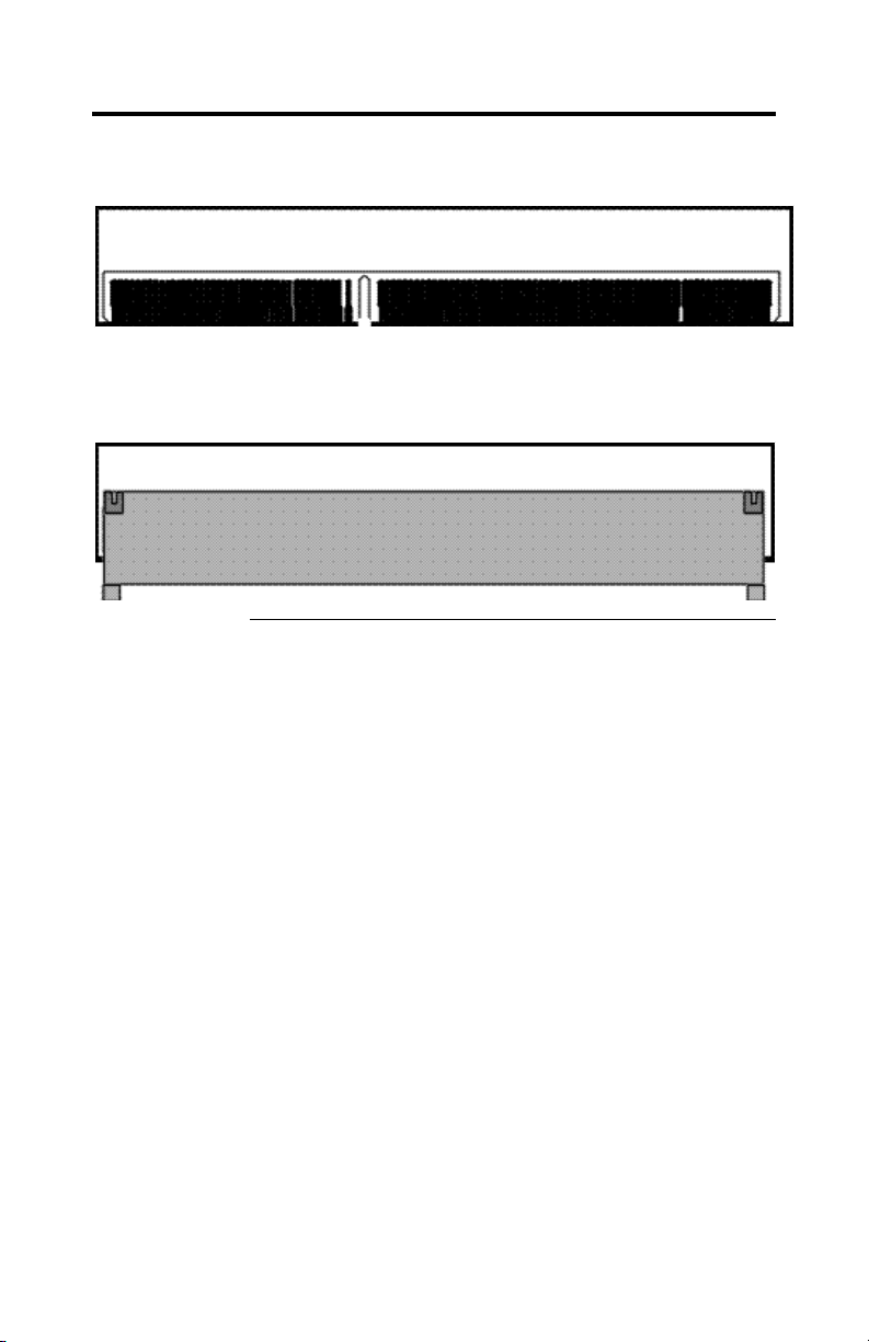
Series 776 CPU Termination Board The Series 776 CPU termination
board is 2.05” by 5.54”.
Series 778 Memory Termination Board The Series 778 memory
termination board is 1.88” by 5.77”.
Cont’d
Megaplex Quad Pentium II Xeon PCI ISA System Guide
6
Page 17
Megaplex Dimensions, Continued
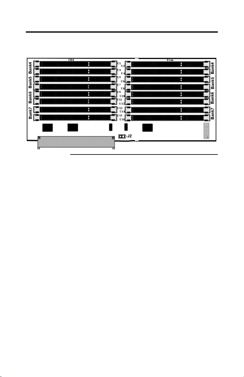
Series 777 Memory Expansion Board The Series 777 memory expansion
board is 6.4” by 13”.
Chapter 1 Hardware Installation
7
Page 18

Installation Steps
Step Action Turn to
1 Unpack the boards. Page 9
2 Configure CPU board. Page 10
3 Configure I/O board. Page 17
4 Install memory. Page 18
5 Install the motherboard in cabinet. Page 25
6 Connect power supply. Page 27
7 Attach connectors. Page 30
8 Test and configure. Page 44
Warning
This motherboard contains sensitive electronic components
that can be easily damaged by static electricity. Follow the
instructions carefully to ensure correct installation and to
avoid static damage.
Avoid Static Electricity
Static electricity can damage the motherboard and other
computer components. Keep the motherboard in the antistatic bag until it is to be installed. Wear an anti-static
wrist grounding strap before handling the motherboard.
Make sure you stand on an anti-static mat when handling
the motherboard. Avoid contact with any component or
connector on any adapter card, printed circuit board, or
memory module. Handle these components by the
mounting bracket.
Megaplex Quad Pentium II Xeon PCI ISA System Guide
8
Page 19

Step 1 Unpack the Boards
The Megaplex system includes the following components:
AMI Part
Number
Description
Series 769 CPU board
Series 770 I/O board
Series 776 Three (3) CPU termination cards
Series 777 Memory expansion card (if ordered)
Series 778 Memory termination card (if the 777 card is not ordered)
Step Action
1 Inspect the cardboard carton for obvious damage. If damaged, call 770-
246-8645. Leave the motherboard in its original packing.
2 Perform all unpacking and installation procedures on a ground-
connected anti-static mat. Wear an anti-static wristband grounded at the
same point as the anti-static mat. Or use a sheet of conductive
aluminum foil grounded through a 1 megohm resistor instead of the
anti-static mat. Similarly, a strip of conductive aluminum foil wrapped
around the wrist and grounded through a 1 megohm resistor serves the
same purpose as the wristband.
3 Inside the carton, the boards are packed in an anti-static bag, and
sandwiched between sheets of sponge. Remove the sponge and the
anti-static bag. Place the boards on a grounded anti-static surface
component side up. Save the original packing material.
4 Inspect the boards for damage. Press down on all ICs mounted in
sockets to verify proper seating. Do not apply power to the board if it
has been damaged.
5 If the boards are undamaged, they are ready to be installed.
Set Jumpers Set all jumpers and install the CPU before placing the
motherboard in the chassis.
Chapter 1 Hardware Installation
9
Page 20

Step 2 Configure CPU Board
See the drawing on page 4 for the jumper locations on the
Megaplex CPU board.
Important
Perform the following steps to configure the boards before
installing a CPU.
J2, J9, J11, J12 CPU Fans
CPU Number Jumper Number
CPU0 J2
CPU1 J9
CPU2 J11
CPU3 J12
These jumpers are the +12V connectors to cooling fans.
The CPU fan cables must be connected to these
connectors. The pinout is:
Pin Number Signal Description
1 Ground
2 +12V
3 Tachometer output from the fan.
Cont’d
Megaplex Quad Pentium II Xeon PCI ISA System Guide
10
Page 21

Step 2 Configure CPU Board, Continued
J3 CPU Clock Ratio J3 is an 8-pin berg on the Series 769 motherboard that
sets the CPU clock ratio. The external clock speed is
always 100 MHz. In the 769 motherboard graphic on page
4, Pin 1 of J3 is marked by the chamfered corner.
J3 Ratio Internal CPU
Speed
Short Pins 1-2
5:1 500 MHz
Short Pins 7-8
Short Pins 1-2
Short Pins 3-4
Short Pins 7-8
Short Pins 5-6
4:1 400 MHz
This is the default
setting.
7:2 350 MHz
Short Pins 7-8
Short Pins 3-4
9:2 450 MHz
Short Pins 7-8
DRAM Speed Settings J8 (on the CPU board) and J2 (on the memory
expansion card) select DRAM speed.
J8/J2 DRAM Speed
OPEN (factory setting) 60ns EDO DRAM
Short 50ns EDO DRAM
Note: The DRAM speed setting should be the same on
both the CPU card and the memory expansion card.
Installing One or Multiple CPUs
Number of CPUs
to be Installed
CPU Installation
1 Install a CPU in any CPU socket and
install a Series 776 CPU terminator card
in the remaining three CPU slots.
2 Install CPUs in any two CPU slots and
install a Series 776 CPU termination
card in the remaining two CPU slots.
4 Install CPUs in all four CPU sockets.
Cont’d
Chapter 1 Hardware Installation
11
Page 22

Step 2 Configure CPU Board, Continued
Warning
Improper CPU installation can damage the CPU and the
motherboard. You must follow the procedures in this
section exactly as documented. Make sure you wear an
antistatic wristband while installing the CPU. Follow all
antistatic procedures described on page 8.
Install CPUs You must mount the CPU Retention Unit before the CPU
is installed. Also the heatsink (provided in the kit) should
be mounted on the CPU before the CPU is inserted in the
slot. The retention mechanism includes:
• base mechanism (4 pieces),
• top covers (4 pieces),
• ears (8 pieces),
• pegs (4 pieces), and
• screws (6-32, ¼ inch) with nuts (16 pieces).
Mount Retention Unit and Heatsink
Step Action
1 Take one base mechanism and place it directly over the CPU Slot 0
(U22). The position of the mounting holes on the mechanism is
asymmetric so that the unit can be placed in only one position over the
slot. The mounting holes on the mechanism superimpose over the
mounting holes on the CPU board.
2 Insert one screw from the bottom of the board in a mounting hole, and
tighten a nut on it from the top. Repeat for the other three holes.
Note: Do not use excessive force to tighten the screws, as this can
damage the board/retention unit.
3 Repeat step 1 for Slot 1 (U30), Slot 2 (U45) and Slot 3 (U56).
Megaplex Quad Pentium II Xeon PCI ISA System Guide
12
Page 23
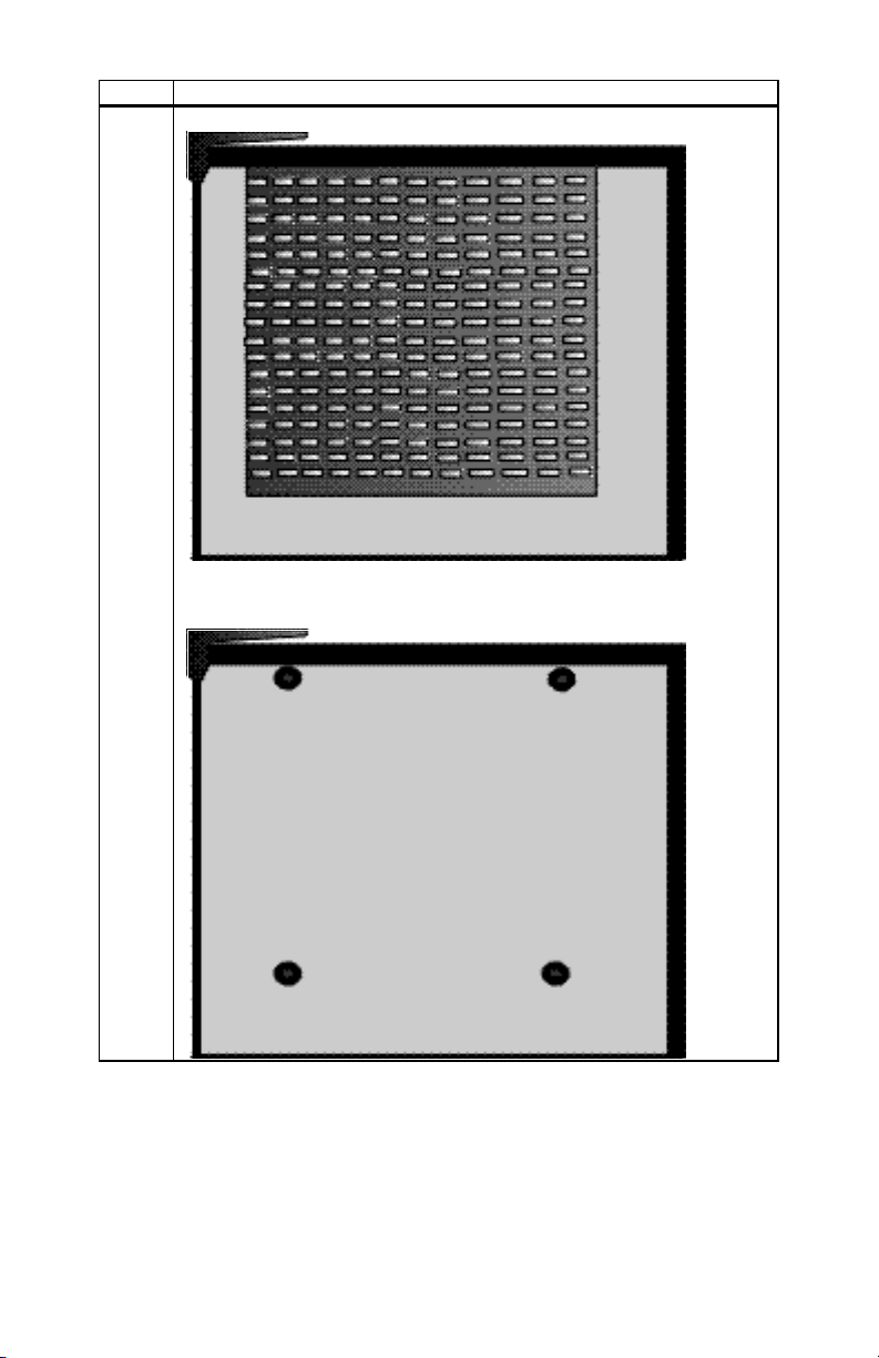
Step Action
4 Mount the heatsink on the CPU as shown:
The CPU has 5 mounting holes on the metal side. Use only the 4 holes
as shown, and screw the heatsink tightly onto the CPU.
Chapter 1 Hardware Installation
13
Page 24
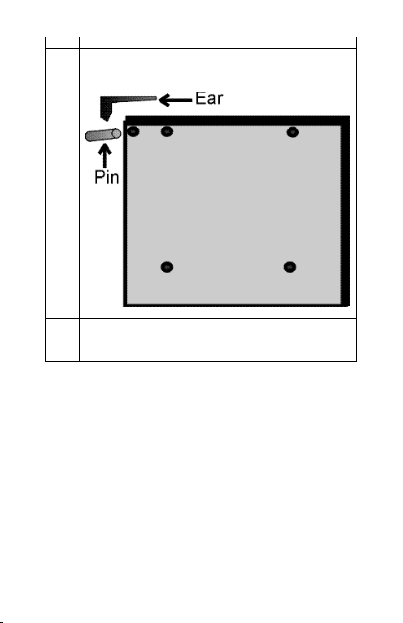
Step Action
5 Mount ears on the CPU as shown. There are two holes on both the top
edges of the CPU, on both sides. Use them to insert the ears into
position.
6 Repeat step 3, 4 and 5 for all the CPUs to be installed.
7 Slide the CPUs in their respective slots from the top. Both the CPU and
the Retention unit have a notch on one side, to prevent the CPU from
sliding into the slot with wrong polarity. Make sure the CPUs are
inserted with the right polarity.
Megaplex Quad Pentium II Xeon PCI ISA System Guide
14
Page 25
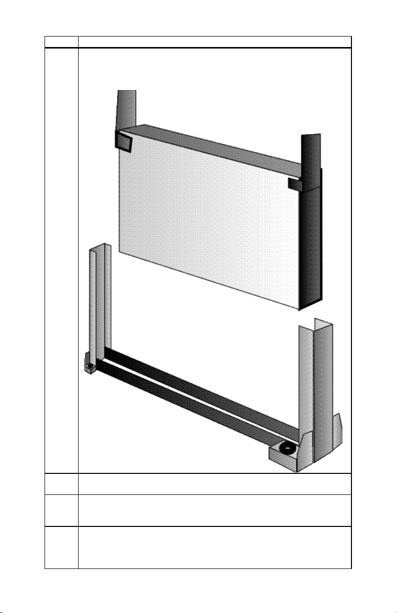
Step Action
8 Push the CPUs all the way to the bottom. When the CPU is seated
properly, the ears cannot be in a standing position. Feel the ears to make
sure they cannot stand up. If they can, the CPU needs to be pushed
further.
9 To pull the CPUs out, just pull the two ears upward into the standing
position, and the CPU will be free from the socket.
10 Insert the pegs into position – two between Slot 0 and Slot 1, and the
other two between Slot 2 & Slot 3. Make sure they go in the right
position, and are seated properly, or the Top unit cannot be mounted.
11 Insert the top units in position. The units are polarized and can be
inserted in only one direction. The polarity is shown with the dots. The
end with the single dot goes in first, and at an inclination. The top will
not sit properly if it is inserted vertically or horizontally to the board.
Chapter 1 Hardware Installation
15
Page 26

Step Action
12 To latch the other end, push lightly from both the top and the side. You
will hear a click when the attachment fits into place. The CPUs and the
retention mechanism should be secured now.
Termination Card The Megaplex motherboard is shipped with a Series 776
CPU termination card that should be installed in the empty
CPU slot.
You must install the termination card in the empty CPU
slots if you install less than four (4) Pentium II Xeon
CPUs. A green LED (J5) lights up if all four CPU slots are
not occupied or the cards or CPUs are not inserted
properly, and the board is powered.
Megaplex Quad Pentium II Xeon PCI ISA System Guide
16
Page 27

Step 3 Configure I/O Board
Install jumpers as shown in the following tables.
J2 CMOS Drain J2 is a 3-pin jumper that can be used to erase the contents
of CMOS RAM, where all system configuration
information is stored.
CMOS Drain J2 Setting
Normal operation (factory setting) Short Pins 1-2
Drain CMOS Short Pins 2-3
J16 VGA Disable J16 is a 2-pin jumper that enables the onboard VGA.
VGA Disable J16 Setting
Enable onboard VGA (factory setting) OPEN
Disable onboard VGA Short
J17 Interrupt Disable J17 is a 2-pin jumper that enables the VGA interrupt.
VGA Interrupt Disable J17 Setting
Disable VGA interrupt (factory
setting)
Short
Enable VGA interrupt OPEN
Chapter 1 Hardware Installation
17
Page 28

Step 4 Install Memory
System Memory System memory for the Megaplex is mounted on the Series
769 CPU board, which supports up to 4 GB of system
memory, and the Series 777 memory card, which supports
an additional 4 GB of system memory. Use 60/50 ns x 72
EDO Mode 3.3V 168-pin ECC buffered memory module
DIMMs (Dual Inline Memory Modules).
The DIMMs in Megaplex are different from the x 36
SIMMs used by most other motherboards. The Megaplex
memory modules are a new JEDEC-standard defined for
8-byte wide common CAS memory supported by most
memory manufacturers. Computers that require a large
amount of memory (such as servers) use DIMMs.
System Memory Requirements You must install DIMMs in all four slots of
a bank. The eight memory banks are Bank0, Bank1,
Bank2, and Bank3 on the CPU board, and Bank4, Bank5,
Bank6, and Bank7 on the memory expansion board. Each
bank of memory has four DIMM sockets.
Within a memory bank, all system memory must be of the
same type. Mixing different types of DIMMs is not
permitted.
All memory banks must have the same type and size
DIMMs. Mixing different types of DIMMs is not
permitted.
Rules for ABP and C2C Memory banks can be populated on either Series
769 or the memory expansion card. If you distribute
memory between the CPU board, and the memory board,
you can use ABP (Address bit permuting) and C2C (Cardto-card interleave) to improve system performance.
Cont’d
Megaplex Quad Pentium II Xeon PCI ISA System Guide
18
Page 29

Step 4 Install Memory, Continued
For 2-bank ABP If the memory card is not participating:
• both banks must be populated consecutively starting
from Bank0, and
• both banks must have the same size and type of
memory.
If the memory card is present, the memory on the card
must meet the same requirements as on the CPU board.
For 4-bank ABP If the memory card is not participating:
• all four banks must be populated consecutively
starting from Bank0, and
• all four banks must have the same size and type of
memory.
If the memory card is present, the memory on the card
must meet the same requirements as on the CPU board.
For 2-bank ABP and C2C
• Memory on both the CPU board and the memory card
must meet 2-bank ABP requirements,
• both the CPU board and the memory card must have
the same size and type of memory, and
• memory on the memory card should be populated in
the same position as the CPU board.
For 4-bank ABP and C2C
• Memory on both the CPU board and the memory card
should meet 4-bank ABP requirements, and
• both the CPU board and the memory card must have
the same size and type of memory.
Note: If you do not plan to use the memory expansion
card, you must terminate the memory expansion slot using
a Series 778 memory terminator card. However, if you do
this, the size of the system memory is limited to 4 GB.
You can store the memory expansion card for future use.
Cont’d
Chapter 1 Hardware Installation
19
Page 30

Step 4 Install Memory, Continued
System Memory Specifications
Item Description
General 3.3 volt, 168 pin, x 72, ECC DIMM (Dual Inline Memory Module)
buffered memory module, EDO 50/60 ns RAS Access Time.
Voltage The memory chips used on the module must be 3.3 volt parts.
Pinout The module pinout is 168 pin (instead of 72 pins on SIMMs).
Data Bits The memory modules are 72 data bit modules
No ECC It is “raw” single CAS DRAM. There is NO ECC logic on the
memory module. ECC (Error Correction Code) is implemented in
the motherboard chipset. ECC does not require parity chips.
Buffers 3.3V volt buffers (typically 163244 or 16244LVT) are used to buffer
the CAS, Address lines, and Write enables.
The x 72 ECC modules are buffered. The Megaplex memory card
cannot use unbuffered memory modules.
Mode Buffered EDO memory. Fast Page Mode is not supported.
DIMM Types 2 MBx72, 4 MBx72, 8 MBx72, 16 MBx72, and 32 MBx72.
Speed 60 ns/50 ns
Maximum Memory Up to 32 DIMMs can be installed to provide up to 8
GB of system memory. The minimum memory
configuration should be four 2 MB x 72 DIMMs (64 MB
of system memory) installed in bank0. You cannot mix
memory types within a memory bank.
Cont’d
Megaplex Quad Pentium II Xeon PCI ISA System Guide
20
Page 31

Step 4 Install Memory, Continued
DRAM Specifications The total amount of system memory is automatically
detected by AMIBIOS. System memory is always fourway interleaved.
DRAM system memory must be populated one bank at a
time. All DIMMs in a bank must be of the same memory
type. Each socket can hold one DIMM. You can use:
• 2 M x 72,
• 4 M x 72,
• 8 M x 72,
• 16 M x 72, or
• 32 M x 72 DIMMs.
Note: “M” in the above list stands for megabits.
Memory Display System memory is reported by AMIBIOS as it boots and
again when the AMIBIOS System Configuration Screen is
displayed just before the operating system boots. The
memory displayed by AMIBIOS on the System
Configuration Screen is 384 KB less than the total memory
installed.
Cont’d
Chapter 1 Hardware Installation
21
Page 32

Step 4 Install Memory, Continued
DRAM Configurations On the CPU board, the following configurations
can be used:
Bank0 Bank1 Bank2 Bank3 Total
2M None None None 64 M
2 M 2 M None None 128 M
2 M 2 M 2 M None 192 M
2 M 2 M 2 M 2 M 256 M
4 M None None None 128 M
4 M 4 M None None 256 M
4 M 4 M 4 M None 384 M
4 M 4 M 4 M 4 M 512 M
8 M None None None 256 M
8 M 8 M None None 512 M
8 M 8 M 8 M None 768 M
8 M 8 M 8 M 8 M 1 G
16 M None None None 512 M
16 M None None None 1 G
16 M 16 M 16 M None 1.5 G
16 M 16 M 16 M 16 M 2 G
32 M None None None 1 G
32 M 32 M None None 2 G
32 M 32 M 32 M None 3 G
32 M 32 M 32 M 32 M 4 G
You can populate the memory module in a similar way.
There is no restriction to the sequence in which the banks
are populated (in the table above, a sequence has been
followed due to space restrictions), but to take advantage
of ABP and C2C, you must follow the rules previously
mentioned.
Note: “M” in the above table stands for megabits.
Megaplex Quad Pentium II Xeon PCI ISA System Guide
22
Cont’d
Page 33
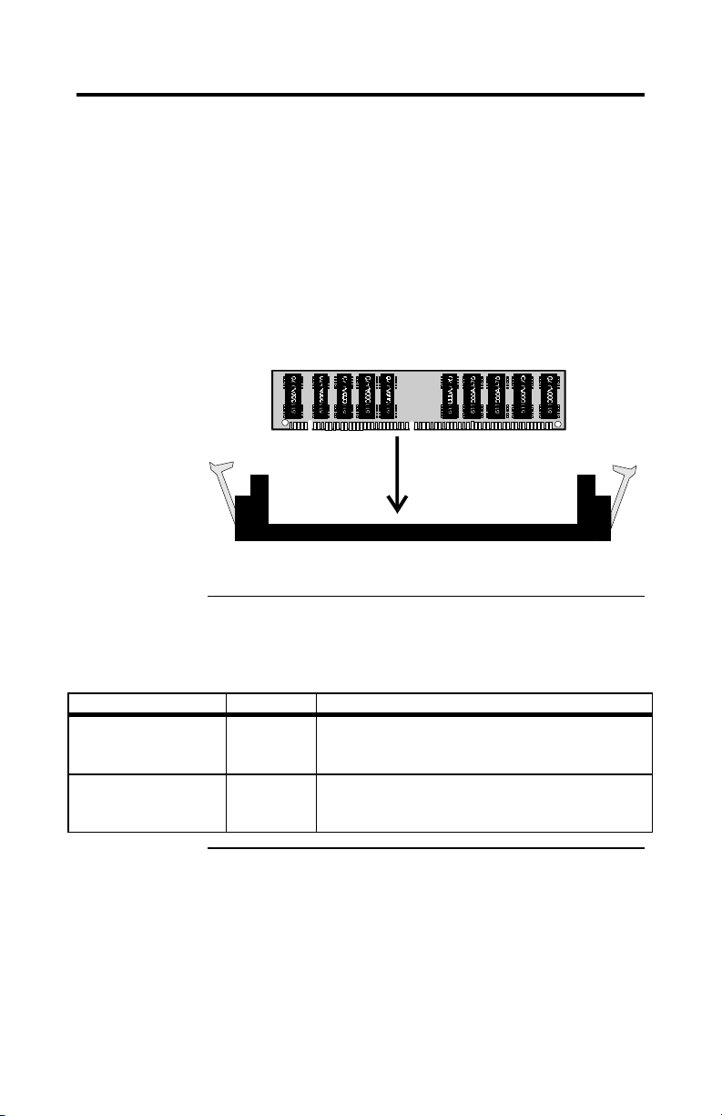
Step 4 Install Memory, Continued
Installing DIMMs The Series 777 Memory Card and Series 769 have 16 x
72 DIMM sockets. These sockets can be filled with either
2 MB x 72, 4 MB x 72, 8 MB x 72, 16 MB x 72, or 32 MB
x 72 DIMMs.
Place the Memory Card on an anti-static mat. Each DIMM
socket has a latch on either end. You cannot open all the
latches at one time, so open one column at a time, install a
DIMM, and then open the second column. With the
component side of the DIMM facing you, insert the DIMM
into the socket and secure the latches on either end of the
DIMM, as shown below:
Populate the CPU board the same way. If you do not use
the memory card, populate only the CPU board.
50 ns DRAM If using 50 ns DRAM, you must set the following jumpers
on both the Series 769 CPU board, and the Series 777
memory board:
Board Jumper
769 CPU Board J8 Select DRAM Speed. J8 is a two-pin berg.
Short 50 ns EDO DRAM
OPEN 60 ns EDO DRAM (factory setting)
777 Memory board J2 Select DRAM Speed. J2 is a two-pin berg
Short 50 ns EDO DRAM
OPEN 60 ns EDO DRAM (factory setting)
Cont’d
Chapter 1 Hardware Installation
23
Page 34

Step 4 Install Memory, Continued
DIMM with Latches Secured
Install Memory Card Insert the Memory Card in the motherboard after you
install the motherboard in the computer case (see Step 5 on
the following page).
Megaplex Quad Pentium II Xeon PCI ISA System Guide
24
Page 35

Step 5 Install Motherboard
The motherboard mounting hole pattern is custom made.
The chassis manufacturer should supply standoffs, and
screws. The hole pattern on the chassis should match the
pattern on the board.
Step Action
1 Place the chassis on an anti-static mat. Connect the chassis to
ground to avoid static damage during installation. Connect an
alligator clip with a wire lead to any unpainted part of the
chassis. Ground the other end of the lead at the same point as
the mat and the wristband.
2 Carefully slide the CPU board (Series 769) into the chassis.
The motherboard should rest level with the chassis.
3 Align the mounting holes on the CPU board with the holes on
the chassis. Place the mounting screws in the holes provided
and tighten them.
4 Mount the memory card (if being used) in the memory card
socket.
5 With extreme caution, place the I/O board in the cabinet so
that the connector on the solder side of the board (J999)
mates with the edge connector (J10) on the CPU board. Press
the boards together to make a firm connection.
Warning: If the boards do not mate properly before they
are pressed together, the connector J999 on the I/O board can
be severely damaged.
6 Repeat step 3 for the I/O board.
Note: The memory connector (J1) on the CPU board must
be occupied. If the Series 777 memory card is not used, the
connector must be terminated by a Series 778 memory
termination card. If the card in J1 is not inserted properly
or is uninstalled, a red LED (J4) lights up as a warning
sign, when the board is powered.
Cont’d
Chapter 1 Hardware Installation
25
Page 36
Step 5 Install Motherboard, Continued
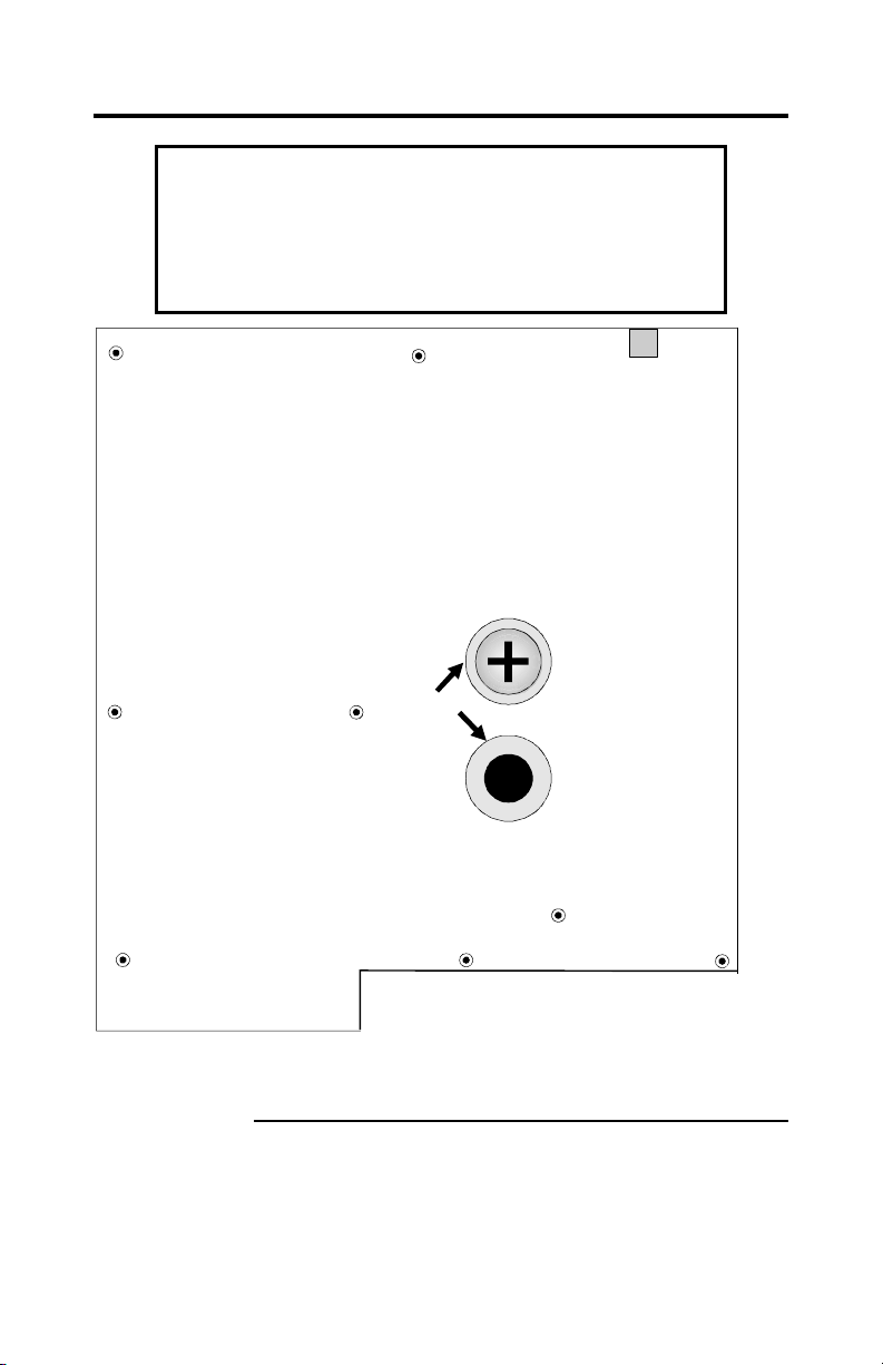
Warning
If using metallic screws, make sure you use them only in the
plated mounting holes. If using metallic screws, make sure
the head of the screw fits completely inside the plated
mounting holes. See the following graphic.
The screw head must not be
larger thanthe plating
aroundthe mounting hole.
Plating
Note: The drawing above is only for illustration and does
not show the exact position of the mounting holes.
Megaplex Quad Pentium II Xeon PCI ISA System Guide
26
Page 37

Step 6 Connect Power Supply
The Megaplex motherboard is designed to fit in a custombuilt chassis. The Megaplex requires four ATX-style
power connectors. Make sure that the power switch is Off
before assembly. Before attaching all components, make
sure that the proper voltage has been selected. Power
supplies often can run on a wide range of voltages and
must be set (usually via a switch) to the proper range.
ATXPS Power Connectors Attach the power supply cables to the ATXPS
power connectors on the motherboard, and the memory
card.
Pin Signal Description Pin Signal Description
1 3.3V 11 3.3V
2 3.3V 12 -12V
3 GND 13 GND
4 +5V 14 PSON (not used by the Megaplex.
The power supply must turn on
without these signals).
5 GND 15 GND
6 +5V 16 GND
7 GND 17 GND
8 PowerGood 18 -5V
9 5VSB (not used by Megaplex) 19 +5V
10 +12V 20 +5V
Cont’d
Chapter 1 Hardware Installation
27
Page 38

Step 6 Connect Power Supply, Continued
Power Requirements At a minimum, one 800 watt power supply generating
95 amps at +5V and 62 amps at +3.3V must be used. A
1000 watt power supply generating 100 amps at +5V, 65
amps at 3.3V, and 20 amps at +12V is recommended.
+5 Volt Requirements The CPU board has the following +5V power
requirements:
• the CPU requirement is 53 amps (approximately 14
amps per CPU), and
• the other logic requires 6 amps.
The I/O board has the following +5.5V requirements:
• the onboard logic requires 11 amps, and
• the PCI cards require 24 amps (two amps per slot).
No 5V power is used for the memory board. The total
power requirement is 94 amps. Add the power
requirements for all adapter cards and CPUs, all hard
drives, CD-ROM drives, SCSI drives, and floppy drives.
See the drive power specifications for all peripheral
devices attached to the computer.
+3.3 Volt Requirements The CPU board has the following +3.3V
requirements:
• the DIMMs require 24 amps (approximately 1.5 amps
per DIMM), and
• the other logic requires one amp.
The I/O board has the following +3.3V requirements:
• the onboard PCI logic requires 12 amps.
The memory board has the following +3.3V requirements:
• the DIMMs require 24 amps (approximately 1.5 amps
per DIMM), and
• the other logic requires one amp.
The total power requirement is 62 amps.
Megaplex Quad Pentium II Xeon PCI ISA System Guide
28
Cont’d
Page 39

Step 6 Connect Power Supply, Continued
+12 Volt Requirements The Megaplex motherboard and CPU fans only use
one amp at +12 volts. But the AT power supply
specifications require that a +12 volt line must be available
for peripheral devices, hard disk drives, and adapter cards.
The +12V load depends on the +12 volt requirements of
the drives and adapter cards installed in the computer. We
recommend 20 amps at +12 volts.
-12V and -5V Requirements 1 amp each should be more than enough.
Cooling Requirements Each CPU dissipates 50 watts of power. To
maintain a junction temperature of less than 158° F (70°
C), adequate cooling must be provided.
AMI provides custom-made heatsinks for the Pentium II
Xeon CPU. The CPU requires cooling by convection. To
maintain a safe operating temperature, the cooling fans
must provide a minimum airflow of 120 lfm horizontally
over the CPUs, though an airflow of 150 lfm is
recommended. It is also recommended that the I/O board
receive the same amount of airflow to dissipate the heat
generated by the expansion cards.
Note: If you plan to use different heatsinks, you must
provide adequate airflow over the heatsinks to maintain a
safe operating temperature.
Chapter 1 Hardware Installation
29
Page 40

Step 7 Attach Connectors
Connectors The Megaplex motherboard connectors are listed below:
Number Connector Turn to
J1 3.3V External battery page 31
J11 KBD / PS2 mouse page 33
J13 Serial port 1 & 2 page 33
J33, J34 USB port 1 & 2 page 34
J15 Parallel port and VGA page 34, 40
J14 Floppy page 35
J10 Primary IDE page 38
J9 Secondary IDE page 38
J8 IDE activity page 39
J31 Turbo LED page 40
J32 External reset page 40
J35 Keyboard lock page 41
J38 Speaker page 41
J21 Chassis intrusion page 41
J28 Chassis fan header page 42
J41 I2C chassis connection page 42
J23 MegaRAC connector page 43
Cable Connector Ends When connecting chassis connectors to the
motherboard, make sure to connect the correct connector
end. Most connector wires are color-coded. Match the
color of the wires leaving the switch or LED to the same
pin on the connector end. There may be more than one
connector with the same color-coded wires. If so, follow
the wire to the switch or LED. All motherboard
components are outlined by a white rectangular box with a
broad arrow at one end. Pin 1 is always at the arrow end of
the white outlined box.
Cont’d
Megaplex Quad Pentium II Xeon PCI ISA System Guide
30
Page 41
Step 7 Attach Connectors, Continued
Connectors When connecting chassis connectors to the motherboard,
make sure to connect the correct connector end. Most
connector wires are color-coded. Match the color of the
wires leaving the switch or LED to the same pin on the
connector end. There may be more than one connector
with the same color-coded wires. If so, follow the wire to
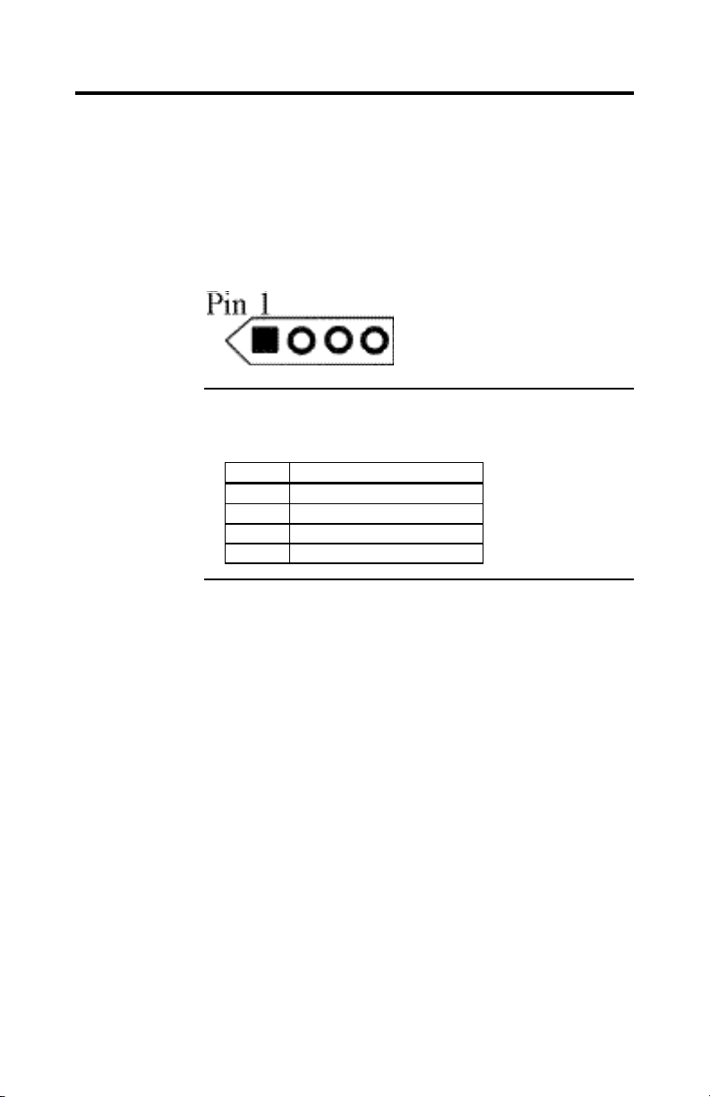
the switch or LED. Pin 1 is always indicated by an arrow,
as shown below:
J1 3.3V External battery connector J1 is a 4-pin berg used for external
battery connections. The pinout is:
Pin Description
1 +3.3V
2 Not connected
3 GND
4 GND
Cont’d
Chapter 1 Hardware Installation
31
Page 42
Step 7 Attach Connectors, Continued
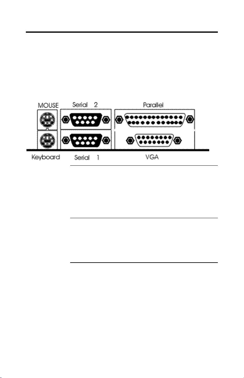
Onboard Adapters The Megaplex I/O connector block at the back of the
motherboard includes:
• a standard PS/2 mouse connector,
• a standard PS/2 keyboard connector,
• two serial ports,
• a parallel port, and
• onboard VGA controller connector.
Additional I/O Connectors The Megaplex also has:
• an IDE controller on the ISA bus (J9 and 10 are IDE
connectors),
• two USB ports, and
• a floppy connector (J14).
Conflicts AMIBIOS minimizes conflicts between onboard and
offboard I/O devices. AMIBIOS automatically checks the
adapter cards installed in the expansion slots on the
Megaplex motherboard for a hard disk or floppy controller
and serial or parallel ports.
Cont’d
Megaplex Quad Pentium II Xeon PCI ISA System Guide
32
Page 43

Step 7 Attach Connectors, Continued
PS/2 Mouse Connector The PS/2 mouse 6-pin miniDIN connector is on top
of the PS/2 miniDIN keyboard connector in the I/O
connector block (shown above). The pinout is:
Pin Signal Description
1 Mouse Data
2 N/C
3 GND
4 VCC
5 Mouse Clock
6 N/C
PS/2 Keyboard Connector The keyboard 6-pin miniDIN connector is
below the mouse connector on the connector I/O block
shown on the previous page. The pinout is:
Pin Signal Description
1 Keyboard Data
2 N/C
3 GND
4 VCC
5 Keyboard Clock
6 N/C
Serial Connectors J13 includes two standard 9-pin D-type connectors are in
the I/O connector block. The serial port base I/O port
address and other settings can be selected in Peripheral
Setup in AMIBIOS Setup. The serial connector pinout is:
Pin Signal Description Pin Signal Description
1 Carrier Detect 6 Data Set Ready
2 Receive Data 7 Request to Send
3 Transmit Data 8 Clear to Send
4 Data Terminal Ready 9 Ring Indicator
5 GND
Cont’d
Chapter 1 Hardware Installation
33
Page 44

Step 7 Attach Connectors, Continued
USB Connectors J33 and J34 J33 and J34 are 4-pin berg connectors that
connect by cable to the USB connectors mounted on the
rear of the cabinet. The pinout is:
Pin Signal Description
1 +5 Volt VCC
2 Data -
3 Data +
4 GND
J15 Parallel Port Connector J15 includes a standard 26-pin parallel port
connector and a VGA connector in the I/O block
connector. The parallel pinout is shown below. Parallel
port settings can be configured in Peripheral Setup in
AMIBIOS Setup.
Pin Signal Description Pin Signal Description
1 STROBE# 2 PD0
3 PD1 4 PD2
5 PD3 6 PD4
7 PD5 8 PD6
9 PD7 10 ACK#
11 BUSY 12 PE
13 SLCT 14 AUTOFD#
15 ERROR# 16 INIT#
17 SLCTIN# 18 GND
19 GND 20 GND
21 GND 22 GND
23 GND 24 GND
25 GND
Cont’d
Megaplex Quad Pentium II Xeon PCI ISA System Guide
34
Page 45
Step 7 Attach Connectors, Continued
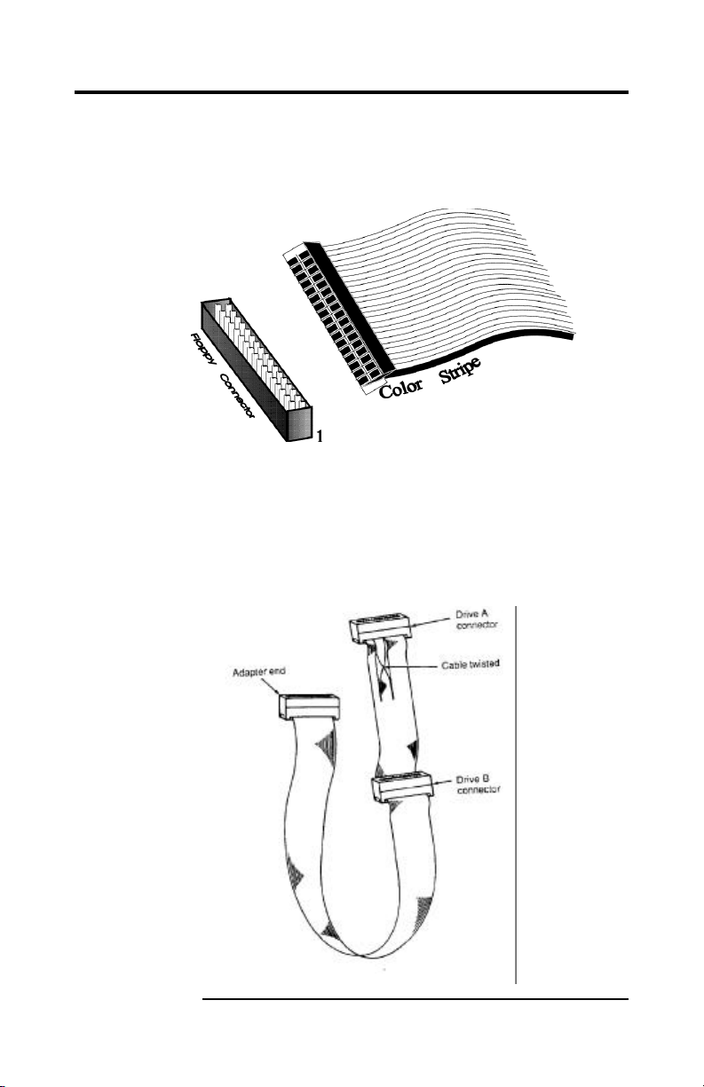
J14 Floppy J14 is a 34-pin dual-inline shrouded connection. Connect
the cable from the floppy drive to J14, as shown below.
Choose Standard Setup and Peripheral Setup to configure
the floppy controller.
The motherboard supports up to two 720 KB, 1.44 MB, or
2.88 MB 3½" drives and 360 KB and 1.2 MB 5¼" drives.
The connecting cable is a 34-pin ribbon connector with
two 34-pin edge connectors for attaching the floppy disk
drives. There is a small twist in the cable between the
floppy connectors. The last (end) connector should be
connected to floppy drive A: as shown below.
Chapter 1 Hardware Installation
35
Page 46

Cont’d
Megaplex Quad Pentium II Xeon PCI ISA System Guide
36
Page 47

Step 7 Attach Connectors, Continued
J14 Floppy Connector Pinout
Pin Use Pin Use
1 GND 2 DENSE1
3 GND 4 N/C
5 GND 6 DRATE0
7 GND 8 -INDEX
9 GND 10 -MOTOR0
11 GND 12 -FDSEL1
13 GND 14 -FDSEL0
15 GND 16 -MOTOR1
17 GND 18 DIR
19 GND 20 21 GND 22 -WDATA
23 GND 24 -WGATE
25 GND 26 -TRK0
27 GND 28 -WRPROT
29 GND 30 -RDATA
31 GND 32 HDSEL
33 GND 34 DSKCHNG
Twist in Floppy Cable
Floppy B to A Floppy B to A Floppy B to A Floppy B to A
10 to 16 12 to 14 14 to 12 16 to 10
11 to 15 13 to 13 15 to 11
Cont’d
Chapter 1 Hardware Installation
37
Page 48
Step 7 Attach Connectors, Continued
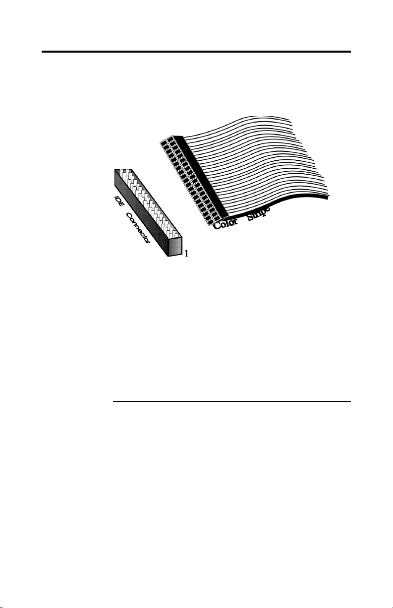
Attach IDE Cable J9 and J10 are the IDE (Integrated Drive Electronics)
hard disk drive connectors. The primary master and the
primary slave IDE drives are connected by cable to J10, as
shown below.
J10 is a 40-pin dual-inline shrouded connector that
connects an ATA IDE drive to the primary onboard IDE
connector. This motherboard supports IDE Mode 0 and
LBA (Logical Block Address) mode, high capacity drives
(over 528 MB), 32-bit data transfer, and fast IDE transfer.
These IDE features are configured in Peripheral Setup in
the AMIBIOS Setup utility. Disable the onboard IDE
interface in Peripheral Setup to use an ISA ESDI, RLL,
MFM, or SCSI hard disk drive.
J9 is similar to J10 and can be used as an additional IDE
connector.
Cont’d
Megaplex Quad Pentium II Xeon PCI ISA System Guide
38
Page 49

Step 7 Attach Connectors, Continued
J9 and J10 Pinout The J9 and J10 pinout is:
Pin Use Pin Use
1 -RESET 2 GND
3 DATA7 4 DATA8
5 DATA6 6 DATA9
7 DATA5 8 DATA10
9 DATA4 10 DATA11
11 DATA3 12 DATA12
13 DATA2 14 DATA13
15 DATA1 16 DATA14
17 DATA0 18 DATA15
19 GND 20 KEY (N/C)
21 N/C 22 GND
23 -IOW 24 GND
25 -IOR 26 GND
27 IDERDY 28 ALE
29 N/C 30 GND
31 INT14 32 -IOCS16
33 HA1 34 N/C
35 HA0 36 HA2
37 -CS0 38 -CS1
39 -IDEACT 40 GND
J8 IDE Indicator LED J8 is a two-pin berg that is attached via a cable to
the externally-mounted IDE Activity LED. This LED
lights when the IDE drive is running. Pin 1 is Anode. Pin 2
is Ground.
Warning
In some IDE drives, you may have to disable the
IDE LED mounted on the drive by changing a
jumper or setting a switch on the IDE drive itself,
before the IDE drive sends a signal to this berg.
Cont’d
Chapter 1 Hardware Installation
39
Page 50

Step 7 Attach Connectors, Continued
Pin 6 Groun
d
Standard VGA Female Connector
J15 VGA Connector J15 is a standard DB15 VGA connector for the
onboard ATI Rage II PCI VGA controller is in the I/O
connector block. The onboard VGA is enabled by default.
You can disable the onboard VGA by placing a jumper on
J23. Connect a VGA monitor to this connector via a
standard VGA cable. The pinout for the standard female
DB15 VGA connector is shown below:
Pin 1 Red
Pin 7 Ground
Pin 2 Green
Pin 8 Ground
Pin 3 Blue
Pin 9 Fuse
Pin 4
Pin 5 Groun d
J31 Turbo LED J31, Turbo LED (light-emitting diode) is not connected.
Pin 10 Ground
Pin 11
Pin 12 MON ID1
Pin 13 HSYNC
Pin 14 VSYNC
Pin 15 MON ID2
J32 External Reset J32 is a two-pin single-inline berg that is attached via a
cable to an externally-mounted reset switch. When the
reset switch is pressed, the system performs a hard reset.
Pin 2 is Ground and Pin 1 is Hard Reset.
Cont’d
Megaplex Quad Pentium II Xeon PCI ISA System Guide
40
Page 51

Step 7 Attach Connectors, Continued
J35 Keyboard Lock J35 is a five-pin single-inline berg that is attached via a
cable to the keyboard lock connector. The computer
chassis may not include the keyboard lock and Power LED
on a single connector. The keyboard lock allows you to
lock the keyboard.
Pin Description
1 LED power
2 LED power
3 GND
4 Keyboard Lock
5 GND
J38 Speaker Connector J38 is a four-pin single-inline berg attached via a
cable to a standard system speaker. AMIBIOS signals
hardware problems through the speaker.
Pin Description
1 Data Out
2 GND
3 N/C
4 GND
J21 Chassis Intrusion Connector J21 is a 2-pin berg which should be
connected by a cable to a NC (Normally Closed) switch on
the chassis. The internal circuitry, when activated,
monitors the state of the chassis, and informs the
administrator if the chassis is opened.
Cont’d
Chapter 1 Hardware Installation
41
Page 52

Step 7 Attach Connectors, Continued
J41 LCD Panel I2C header J41 is a 4-pin berg connector connected by a
cable to the LCD panel on the chassis. The system
communicates to the I2C device on the LCD panel through
this connector. The pinout is:
Pin Description
1 I2C Clock
2 GND
3 I2C Data
4 GND
J28 Chassis Fan Header J28 is a 26-pin dual-in-line berg connected by a
cable to the chassis fans, and the external battery backup.
The internal circuitry monitors the state of the chassis
cooling fans, and the battery, and informs the administrator
of any failure. The +12V pins supply power to the fans,
while the fan pins read the tachometer lines of their
respective fans. Up to eight fans can be monitored at a
time. The J28 pinout is:
Pin Description Pin Description
1 Fan 0 2 GND
3 Fan 1 4 GND
5 Fan 2 6 GND
7 Fan 3 8 GND
9 Fan 4 10 GND
11 Fan 5 12 GND
13 Fan 6 14 External battery (+)
15 External battery (+) 16 +12V
17 +12V 18 +12V
19 GND 20 +12V
21 +12V 22 +12V
23 GND 24 +12V
25 Fan 7 26 +12V
Cont’d
Megaplex Quad Pentium II Xeon PCI ISA System Guide
42
Page 53

Step 7 Attach Connectors, Continued
J23 MegaRAC Connector J23 is a shrouded 20-pin connector connected by
a cable to the RAC (Remote Access Control) expansion
card. The administrator can remotely control the system, if
the RAC is implemented. This connector is custom made
for the AMI MegaRAC card. The pinout is:
Pin Description Pin Description
1 SMI 2 I2C clock
3 Not connected 4 GND
5 Not connected 6 I2C data
7 Not connected 8 Not connected
9 Not connected 10 Not connected
11 Reset 12 GND
13 GND 14 Not connected
15 Not connected 16 GND
17 Not connected 18 Not connected
19 Not connected 20 GND
Chapter 1 Hardware Installation
43
Page 54

Step 8 Test and Configure
Review the following points before powering up:
• make sure that all adapter cards are seated properly,
• make sure all connectors are properly installed,
• make sure the CPU is seated properly,
• make sure there are no screws or other foreign
material on the motherboard,
• plug the system into a surge-protected power strip,
and
• make sure blank back panels are installed on the back
of the chassis to minimize RF emissions.
Start the Test Plug everything in and turn on the switch. If there are any
signs of a problem, turn off the unit immediately. Reinstall
the connectors. Call Technical Support if there are
BIOS Errors If the system operates normally, a display should appear
problems.
on the monitor. The BIOS Power On Self Test (POST)
should execute.
If POST does not run successfully, it will beep or display
error messages. Beeps indicate a serious problem with the
system configuration or hardware. The Beep Code
indicates the problem. AMIBIOS Beep Codes are defined
in the AMIBIOS Technical Reference. Make sure the
affected part is properly seated and connected. An error
message is displayed if the error is less serious. Recheck
the system configuration or the connections.
Configure the System Run AMIBIOS Setup. Load the Optimal settings.
Enter the requested information and save the configuration
data in NVRAM (Non-Volatile Random Access Memory
(also called CMOS RAM). The system will then reset, run
POST, and boot the operating system. See page 47 for
information on configuring the computer.
Megaplex Quad Pentium II Xeon PCI ISA System Guide
44
Page 55

Chapter 1 Hardware Installation
45
Page 56

Page 57

®
2 AMIBIOS
In ISA computers, the system parameters (such as
amount of memory, type of disk drives and video
displays, and many other elements) are stored in CMOS
RAM. Unlike the DRAM (dynamic random access
memory) that is used for standard system memory,
CMOS RAM requires very little power. When the
computer is turned off, a back-up battery provides power
to CMOS RAM, which retains the system parameters.
Every time the computer is powered-on, the computer is
configured with the values stored in CMOS RAM by the
system BIOS, which gains control when the computer is
powered on.
The system parameters are configured by a system BIOS
Setup utility. Historically, BIOS Setup utilities have been
character-based, required keyboard input, and have had
user interfaces that were not very intuitive.
System Initialization Depending on the size of system memory, the BIOS
can take up to eight minutes to initialize system memory.
The system memory must be initialized to support ECC
(error correction.) If you enable Quickboot or press the
escape (Esc) key, BIOS will display the installed
memory and it will take the following amount of time to
initialize system memory:
Setup
• 15 – 20 seconds for 512 MB,
• 45 – 60 seconds for 1 GB,
• 2:00 – 2:30 minutes for 2 GB,
• 4 minutes for 4 GB, and
• 8 minutes for 8 GB.
If you press the Delete key during this time, BIOS will
go immediately into setup. If you want a normal boot,
wait the complete time for the system memory to
initialize.
Starting AMIBIOS Setup As POST executes, the following appears:
Hit DEL if you want to run SETUP
Press Delete to run AMIBIOS Setup.
Chapter 2 AMIBIOS Setup 47
Page 58

AMIBIOS Setup Menu
The AMIBIOS Setup main menu appears as follows.
Each menu item is described in this chapter.
AMIBIOS HIFLEX SETUP UTILITY VERSION 1.18
© 1998 American Megatrends, Inc. All Rights Reserved.
Standard CMOS Setup
Advanced CMOS Setup
Power Management Setup
PCI / Plug And Play Setup
Peripheral Setup
Auto-Detect Hard Disks
Change User Password
Change Supervisor Password
Change Language Setting
Auto Configuration With Optimal Settings
Auto Configuration With Fail-Safe Settings
Save Settings And Exit
Exit Without Saving
Standard CMOS setup for changing time, date, hard disk type, etc.
Esc:Exit ↑↓:Sel F2/F3:Color F10:Save & Exit
Megaplex Quad Pentium II Xeon PCI ISA System Guide
48
Page 59

Section 1 Standard Setup
Choose Standard CMOS Setup from the AMIBIOS
Setup main menu. All Standard Setup options are
described in this section. The Standard CMOS Setup
screen is shown below.
(C)1998 American Megatrends, Inc. All Rights Reserved
AMIBIOS SETUP-STANDARD CMOS SETUP
Date (mm/dd/yyyy): Tue Sep 1,1998 Base Memory: 640 KB
Time (hh/mm/ss) : 16:05:13 Extd Memory: 255 KB
Floppy Drive A: 1.44MB 3½
Floppy Drive B: Not Installed
LBA Blk PIO 32Bit
Pri Master: Auto 42 40 981 5 981 17 Off Off Auto On
Type Size Cyln Head Wpcom Sec Mode Mode Mode Mode
Pri Slave: Not Installed
Sec Master: Not Installed
Sec Slave: Not Installed
Boot Sector Virus Protection Disabled
Month: Jan – Dec ESC:Exit ↑↓:Sel
Day: 01 – 31 PgUp/PgDn:Modify
Year: 1901 – 2099 F2/F3:Color
Date/Time Select Standard CMOS Setup from the AMIBIOS Setup
main menu. Highlight Date or Time using the arrow
keys. Enter new values through the keyboard. Press the
<Tab> key or the arrow keys to move between fields.
The date must be entered in MM/DD/YYYY format. The
time is entered in HH:MM:SS format. The time is in 24hour format, also. For example, 5:30 a.m. appears as
05:30:00, and 5:30 p.m. as 17:30:00.
Press <PgUp> or <PgDn> after you have selected an
option to display the complete list of valid setting in the
bottom section of the screen. For example, when the
cursor is in the Date field, the options for month, day,
and year display, as seen in the screen above.
Cont’d
Chapter 2 AMIBIOS Setup
49
Page 60

Standard Setup, Continued
Floppy Drive A: and B: Move the cursor to these fields via ↑ and ↓ and
select the floppy type. The settings are 360 KB 5¼ inch,
1.2 MB 5¼ inch, 720 KB 3½ inch, or 1.44 MB 3½ inch.
Boot Sector Virus Protection This option is near the bottom of the
Standard Setup screen. The settings are Enabled or
Disabled. Choose Enabled to enable boot sector
protection. AMIBIOS displays a warning when any
program (or virus) issues a Disk Format command or
attempts to write to the boot sector of the hard disk drive.
If enabled, the following appears when a write is
attempted to the boot sector. You may have to type N
several times to prevent the boot sector write.
Boot Sector Write!!!
Possible VIRUS: Continue (Y/N)? _
The following appears after any attempt to format any
cylinder, head, or sector of any hard disk drive via the
BIOS INT 13 Hard Disk Drive Service:
Format!!!
Possible VIRUS: Continue (Y/N)? _
Cont’d
Megaplex Quad Pentium II Xeon PCI ISA System Guide
50
Page 61

Standard Setup, Continued
Primary Master, Primary Slave, Secondary Master, Secondary Slave
Select one of these hard disk drives to configure the hard
disk drive named in the option. Press ENTER to
autodetect. The settings for each of these drives are:
Setting How to Configure
1 – 46
Predefined types
USER:
Enter parameters
manually
AUTO:
Set parameters
automatically on
each boot
If you are configuring an old MFM drive and you know
the drive type, select the correct drive type between 1 – 46.
If you are installing an old MFM drive and you do not
know the drive type or the drive parameters do not match
the drive parameters for types 1 – 46, enter the correct hard
disk drive parameters.
Select Auto to let AMIBIOS determine the parameters.
Click on OK when AMIBIOS displays the drive
parameters. You can also change these parameters if you
do not think AMIBIOS detected the drive parameters
correctly or if you want to enable an enhanced IDE feature.
You can modify these parameters as follows:
Select LBA/Large Mode. Select On if the drive has a
capacity greater than 540 MB.
Select Block Mode. Select On to allow block mode data
transfers.
Select 32-Bit Mode. Select On to allow 32-bit data
transfers.
Select the PIO Mode. It is best to select Auto to allow
AMIBIOS to determine the PIO mode. If you select a PIO
mode that is not supported by the IDE drive, the drive will
not work properly. If you are absolutely certain that you
know the drive’s PIO mode, select PIO mode 0 - 5, as
appropriate.
CDROM:
Use for ATAPI
CDROM drives
ARMD:
Use for LS120,
MO, Iomega Zip
drives
Select CDROM if configuring an ATAPI drive. AMIBIOS
displays the drive parameters.
Select this setting if you are configuring an LS120, MO
(Magneto-Optical), or Iomega Zip drive.
Cont’d
Chapter 2 AMIBIOS Setup
51
Page 62

Standard Setup, Continued
Entering Drive Parameters You can also enter the hard disk drive
parameters. The drive parameters are:
Parameter Description
Type The number for a drive with certain identification
parameters.
Size The formatted size of the drive is the number of heads
times the number of cylinders times the number of sectors
per track times 512 (bytes per sector).
Cylinders The number of cylinders in the disk drive.
Heads The number of heads.
Write
Precompensation
Landing Zone This number is the cylinder location where the heads
Sectors The number of sectors per track. MFM drives have 17
LBA Mode LBA (Logical Block Addressing) is a method of
Blk Mode Block mode boosts IDE drive performance by increasing
PIO Mode IDE PIO mode programs timing cycles between the IDE
32Bit Mode Hard disk drives connected to the computer via the ISA
The actual physical size of a sector gets progressively
smaller as the track diameter diminishes. Yet each sector
must still hold 512 bytes. Write precompensation circuitry
on the hard disk compensates for the physical difference
in sector size by boosting the write current for sectors on
inner tracks. This parameter is the track number on the
disk surface where write precompensation begins.
normally park when the system is shut down.
sectors per track. RLL drives have 26 sectors per track.
ESDI drives have 34 sectors per track. SCSI and IDE
drives have even more sectors per track.
addressing data on a disk drive. In LBA mode, the
maximum drive capacity is 8.4GB.
the amount of data transferred. Only 512 bytes of data can
be transferred per interrupt if block mode is not used.
Block mode allows transfers of up to 64 KB per interrupt.
drive and the programmable IDE controller. As the PIO
mode increases, the cycle time decreases.
bus transfer data 16 bits at a time. An IDE drive on the
PCI bus or VL-Bus can use a 32-bit data path.
Cont’d
Megaplex Quad Pentium II Xeon PCI ISA System Guide
52
Page 63

Standard Setup, Continued
Hard Disk Drive Types
Type Cylinders Heads Write
Precompensation
1 306 4 128 305 17 10 MB
2 615 4 300 615 17 20 MB
3 615 6 300 615 17 31 MB
4 940 8 512 940 17 62 MB
5 940 6 512 940 17 47 MB
6 615 4 65535 615 17 20 MB
7 462 8 256 511 17 31 MB
8 733 5 65535 733 17 30 MB
9 900 15 65535 901 17 112 MB
10 820 3 65535 820 17 20 MB
11 855 5 65535 855 17 35 MB
12 855 7 65535 855 17 50 MB
13 306 8 128 319 17 20 MB
14 733 7 65535 733 17 43 MB
16 612 4 0 663 17 20 MB
17 977 5 300 977 17 41 MB
18 977 7 65535 977 17 57 MB
19 1024 7 512 1023 17 60 MB
20 733 5 300 732 17 30 MB
21 733 7 300 732 17 43 MB
22 733 5 300 733 17 30 MB
23 306 4 0 336 17 10 MB
24 925 7 0 925 17 54 MB
25 925 9 65535 925 17 69 MB
26 754 7 754 754 17 44 MB
27 754 11 65535 754 17 69 MB
28 699 7 256 699 17 41 MB
29 823 10 65535 823 17 68 MB
30 918 7 918 918 17 53 MB
31 1024 11 65535 1024 17 94 MB
32 1024 15 65535 1024 17 128 MB
33 1024 5 1024 1024 17 43 MB
34 612 2 128 612 17 10 MB
35 1024 9 65535 1024 17 77 MB
36 1024 8 512 1024 17 68 MB
37 615 8 128 615 17 41 MB
38 987 3 987 987 17 25 MB
39 987 7 987 987 17 57 MB
40 820 6 820 820 17 41 MB
41 977 5 977 977 17 41 MB
42 981 5 981 981 17 41 MB
43 830 7 512 830 17 48 MB
44 830 10 65535 830 17 69 MB
45 917 15 65535 918 17 114 MB
46 1224 15 65535 1223 17 152 MB
AMIBIOS automatically sets IDE drive parameters. Select USER to enter
MFM, ESDI, or RLL drive parameters. Select Not Installed for SCSI
drives. Select CDROM for CD-ROM drives.
Landing
Zone
Sectors Size
Chapter 2 AMIBIOS Setup
53
Page 64

Section 2 Advanced CMOS Setup
Choose Advanced CMOS Setup from the AMIBIOS
Setup main menu. Advanced CMOS Setup options are
displayed by highlighting the option using the arrow
keys. All Advanced CMOS Setup options are described
in this section.
Primary Display This option configures the type of monitor attached to
the computer. The settings are Absent, VGA/EGA,
CGA40x25, CGA80x25, or Mono. The Optimal and FailSafe default settings are VGA/EGA.
PS/2Mouse Support Set this option to Enabled to enable AMIBIOS
support for a PS/2-type mouse. The settings are Enabled
or Disabled. If IRQ12 is required to be free for PCI
cards, then you must disable this option. If you disable
this option, you cannot use a PS/2-type mouse. The
Optimal and Fail-Safe default settings are Enabled.
Display BIOS P.O.S.T. Messages Set this option to display BIOS
messages during the Power On Self Test. The settings
are Yes or No. The Optimal and Fail-Safe default settings
are Yes.
Display Add-On ROM Messages Set this option to display messages
when you add an optional ROM. The settings are Yes or
No. The Optimal and Fail-Safe default settings are Yes.
Pause-On Configuration Screen Set this option to pause at the
configuration screen during setup. The settings are
Disabled, 1 sec, 2 sec, 3 sec, 4 sec, 5 sec, 6 sec, 7 sec, 8
sec, 9 sec, or 10 sec. The Optimal and Fail-Safe default
settings are 10 sec.
BootUp Num Lock Set this option to On to turn the Num Lock key On at
system boot. The settings are On or Off. The Optimal and
Fail-Safe default settings are On.
Cont’d
Megaplex Quad Pentium II Xeon PCI ISA System Guide
54
Page 65

Advanced CMOS Setup, Continued
Password CheckThis option enables the password check option every
time the system boots or the end user runs Setup. If
Always is chosen, a user password prompt appears every
time the computer is turned on. If Setup is chosen, the
password prompt appears if AMIBIOS is executed. See
page 72 for instructions on changing a password. The
Optimal and Power-On defaults are Setup.
MPS Mode Select 1.4 to boot to SCO UNIX 5.0/5.04, Novell 5.0,
Windows NT 3.5/4.0/5.0, and OS/2 Advanced Server
Version 4. Select 1.1 to boot to Unix Ware Version 7.
The Optimal and Fail-Safe default settings are 1.4.
Boot to Novell 4.X Select Yes to boot to Novell 3.X or 4.X. The Optimal
and Fail-Safe settings are No.
Boot To OS/2 Set this option to Yes if running OS/2 operating system
and using more than 64 MB of system memory on the
motherboard. The settings are Yes or No. The Optimal
and Fail-Safe default settings are No.
S.M.A.R.T. for Hard Disks Set this option to Enabled to permit
AMIBIOS to use the SMART (Self Monitoring Analysis
and Reporting Technology) protocol for reporting server
system information over a network. The settings are
Enabled or Disabled. The Optimal and Fail-Safe default
settings are Disabled.
Quick Boot Set this option to Enabled to instruct AMIBIOS to boot
quickly when the computer is powered on. The settings
are Disabled or Enabled. If Quickboot is enabled, BIOS
will not test the system memory; memory will be
initialized only. The Optimal and Fail-Safe default
settings are Disabled.
Cont’d
Chapter 2 AMIBIOS Setup
55
Page 66

Advanced CMOS Setup, Continued
1st Boot Device This option sets the type of device for the first boot
drives that the AMIBIOS attempts to boot from after
AMIBIOS POST completes. The settings are Disabled,
SCSI, NETWORK, Floppy, ARMD-FDD, ARMD-HDD,
ATAPI CDROM, I2O, 1st IDE-HDD, 2nd IDE-HDD, 3
IDE HDD, or 4th IDE-HDD. The default setting is
Floppy. The Optimal and Fail-Safe default settings are
Floppy.
2nd Boot Device This option sets the type of device for the second boot
drives that the AMIBIOS attempts to boot from after
AMIBIOS POST completes. The settings are Disabled,
SCSI, Floppy, ARMD-FDD, ARMD-HDD, ATAPI
CDROM, 1st IDE-HDD, 2nd IDE-HDD, 3rd IDE HDD,
or 4th IDE-HDD. The default setting is Disabled. The
Optimal and Fail-Safe default settings are 1st IDE.
3rd Boot Device This option sets the type of device for the third boot
drives that the AMIBIOS attempts to boot from after
AMIBIOS POST completes. The settings are Disabled,
Floppy, ARMD-FDD, ARMD-HDD, ATAPI CDROM, 1
IDE-HDD, 2nd IDE-HDD, 3rd IDE HDD, or 4th IDEHDD. The default setting is Disabled. The Optimal and
Fail-Safe default settings are SCSI.
4th Boot Device This option sets the type of device for the fourth boot
drives that the AMIBIOS attempts to boot from after
AMIBIOS POST completes. The settings are Disabled,
Floppy, ARMD-FDD, ARMD-HDD, ATAPI CDROM, 1
IDE-HDD, 2nd IDE-HDD, 3rd IDE HDD, or 4th IDEHDD. The default setting is Disabled. The Optimal and
Fail-Safe default settings are Disabled.
Cont’d
rd
st
st
Megaplex Quad Pentium II Xeon PCI ISA System Guide
56
Page 67

Advanced Setup, Continued
Try Other Boot Devices Set this option to Yes to instruct AMIBIOS to
attempt to boot from any other drive in the system if it
cannot find a boot drive among the drives specified in
the 1st Boot Device, 2nd Boot Device, 3rd Boot Device,
and 4th Boot Device options. The settings are Yes or No.
The Optimal and Fail-Safe default settings are No.
Cache Bus ECC The settings are Disabled or Enabled. The Optimal and
Fail-Safe settings are Enabled.
Watch Dog Timer Set this option to Enabled to use the watch dog timer.
If you enable the watch dog timer, the system will
automatically reboot if the hardware detects no bus
activity for approximately 1.2 seconds. The Optimal and
Fail-Safe settings are Disabled.
Internal Cache This option sets the type of caching algorithm used by
the L1 internal cache memory. The settings are
WriteBack, WriteThru, or Disabled. The Optimal and
Fail-Safe default settings are WriteBack.
External Cache This option sets the type of caching algorithm used by
the external cache memory. The settings are WriteBack,
WriteThru, or Disabled. The Optimal and Fail-Safe
default settings are WriteBack.
System BIOS Cacheable When set to Enabled, the contents of the F0000h
system memory segment can be read from or written to
cache memory. The contents of this memory segment are
always copied from the BIOS ROM to system RAM for
faster execution. The settings are Enabled or Disabled.
The default setting is Enabled. The Optimal setting is
Enabled. The Fail-Safe setting is Disabled.
Cont’d
Chapter 2 AMIBIOS Setup
57
Page 68

Advanced Setup, Continued
C000,16K Shadow
C400,16K Shadow This option controls the location of the contents of
video ROM. The settings are:
Setting Description
Enabled The contents of the video ROM area (C0000h - C7FFFh) are written
to the corresponding address in RAM.
Cached The contents of the video ROM area (C0000h - C7FFFh) are written
to the corresponding RAM address and can be read from or written
to cache memory.
Disabled The video ROM is not copied to RAM. The contents of the video
ROM cannot be read from or written to cache memory.
The Optimal and Fail-Safe default settings are Cached.
C800,16K Shadow
CC00,16K Shadow
D000,16K Shadow
D400,16K Shadow
D800,16K Shadow
DC00,16K Shadow These options enable shadowing of the contents of
the ROM area in the option title.
Setting Description
Enabled The contents of the ROM area are written to the corresponding address in
RAM for faster execution.
Cached The contents of the ROM area are written to the corresponding RAM
address and can be read from or written to cache memory.
Disabled The ROM is not copied to RAM. The contents of the video ROM cannot
be read from or written to cache memory.
The Optimal and Fail-Safe default settings are Cached.
Megaplex Quad Pentium II Xeon PCI ISA System Guide
58
Page 69

Section 3 Power Management Setup
Choose Power Management Setup from the AMIBIOS
Setup main menu. All Power Management Setup options
are described in this section.
ACPI Aware O/S Set this option to Yes if the operating system you are
running under complies with the Intel ACPI (Advanced
Configuration and Power Interface) specification. The
settings are Yes or No. The Optimal and Fail-Safe default
settings are No.
Power Management/APM Set this option to Enabled to enable the chipset
power management and APM (Advanced Power
Management) features. The settings are Enabled or
Disabled. The Optimal and Fail-Safe default settings are
Disabled.
Power Button Function This option specifies how the power button
mounted externally on the computer chassis is used. The
settings are:
Setting Description
On/Off Pushing the power button turns the computer on or off.
Suspend Pushing the Power button places the computer in Suspend mode
or Full On power mode.
The Optimal and Fail-Safe default settings are On/Off.
Green PC Monitor Power State This option specifies the power state that
the green PC-compliant video monitor enters when
AMIBIOS places it in a power saving state after the
specified period of display inactivity has expired. The
settings are Stand By, Suspend, or Off. The Optimal
default setting is Suspend. The Fail-Safe default setting is
Stand By.
Cont’d
Chapter 2 AMIBIOS Setup
59
Page 70

Power Management Setup, Continued
Video Power Down Mode This option specifies the power state that the
video subsystem enters when AMIBIOS places it in a
power saving state after the specified period of display
inactivity has expired. The settings are Standby, Suspend
or Disabled. The Optimal default setting is Stand By. The
Fail-Safe default setting is Disabled.
Hard Disk Power Down Mode This option specifies the power
conserving state that the hard disk drive enters after the
specified period of hard drive inactivity has expired. The
settings are Disabled, Stand By, or Suspend. The Optimal
default setting is Suspend. The Fail-Safe default setting is
Disabled.
Hard Disk Time Out (Minute) This option specifies the length of a
period of hard disk drive inactivity. When this length of
time expires, the computer enters power-conserving state
specified in the Hard Disk Power Down Mode option.
The settings are Disabled, 1 min. (minute), 2 min, 3 min.,
4 min., 5 min., 6 min, 7 min., 8 min., 9 min., 10 min., 11
min., 12 min., 13 min, or 14 min. The Optimal and Fail-
Safe default settings are Disabled.
Power Saving Type The settings are POS, Sleep, Stop Clock, and Deep
Sleep. The Optimal and Fail-Safe default settings are
POS.
Standby/Suspend Timer Unit This option specifies the unit of time used
for the Standby and Suspend timeout periods. The
settings are 32 sec, 4 msec, 4 min, or 4 sec. The Optimal
and Fail-Safe default settings are 4 min.
Cont’d
Megaplex Quad Pentium II Xeon PCI ISA System Guide
60
Page 71

Power Management Setup, Continued
Standby Time Out This option specifies the length of a period of system
inactivity while in Full power on state. When this length
of time expires, the computer enters Standby power state.
The settings are Disabled, 4 min, 8 min, up to and
including 508 minutes, in increments of 4 minutes. The
Optimal and Fail-Safe default settings are Disabled.
Suspend Time Out This option specifies the length of a period of system
inactivity while in Standby state. When this length of
time expires, the computer enters Suspend power state.
The settings are Disabled, 4 min, 8 min, up to and
including 508 minutes, in increments of 4 minutes. The
Optimal and Fail-Safe default settings are Disabled.
Slow Clock Ratio This option specifies the speed at which the system
clock runs in the Standby Mode power saving state. The
settings are expressed as a percentage between the
normal CPU clock speed and the CPU clock speed when
the computer is in the power-conserving state. The
settings are 0 - 12.5%, 12.5% - 25%, 25% - 37.5%,
37.5% -50% , 50% - 62.5%, 62.5% - 75%, or 75% -
87.5%. The Optimal and Fail-Safe default settings are
50% - 62.5%.
Display Activity When set to Monitor, this option enables event
monitoring on the video display. If set to Monitor and the
computer is in a power saving state, AMIBIOS watches
for display activity. The computer enters the Full On
state if any activity occurs. AMIBIOS reloads the
Standby and Suspend timeout timers if display activity
occurs. The settings are Monitor or Ignore. The Optimal
and Fail-Safe default settings are Ignore.
Chapter 2 AMIBIOS Setup
Cont’d
61
Page 72

Power Management Setup, Continued
Device 6 (Serial Port 1)
Device 7 (Serial Port 2)
Device 8 (Parallel Port)
Device 5 (Floppy Disk)
Device 0 (Primary Master IDE)
Device 1 (Primary Salve IDE)
Device 2 (Secondary Master IDE)
Device 3 (Secondary Slave IDE) When set to Monitor, these options
enable event monitoring on the specified hardware
interrupt request line. If set to Monitor and the computer
is in a power saving state, AMIBIOS watches for activity
on the specified IRQ line. The computer enters the Full
On state if any activity occurs. AMIBIOS reloads the
Standby and Suspend timeout timers if activity occurs on
the specified IRQ line.
The settings for each of these options are Monitor or
Ignore. The Optimal default setting is Ignore, except for
Device 0 (Primary Master IDE), which has an Optimal
default setting of Monitor. The Fail-Safe default setting
is Monitor.
Megaplex Quad Pentium II Xeon PCI ISA System Guide
62
Page 73

Section 4 PCI/PnP Setup
Choose PCI/PnP Setup from the AMIBIOS Setup main
menu. All PCI/PnP Setup options are described in this
section.
USB Function Set this option to Enabled to enable the USB (universal
serial bus). The settings are Disabled or Enabled. The
Optimal and Fail-Safe settings are Disabled.
USB KB/Mouse Legacy Support Set this option for the USB to support
older keyboard and mouse operation. The settings are
Disabled, Keyboard, Auto or Keyb+Mouse. The Optimal
and Fail-Safe settings are Disabled.
Port 64/60 Emulation Set this option to Enabled to enable Port 64/60
emulation. The Optimal and Fail-Safe settings are Disabled.
Plug and Play-Aware OS Set this option to Yes if the operating system in
this computer follows the Plug and Play specification.
Windows 95 is PnP-aware. The settings are Yes or No.
The default setting is Yes. The Optimal and Fail-Safe
default settings are No.
PCI VGA Palette Snoop When this option is set to Enabled, multiple
VGA devices operating on different buses can handle
data from the CPU on each set of palette registers on
every video device. Bit 5 of the command register in the
PCI device configuration space is the VGA Palette
Snoop bit (0 is disabled). For example: if there are two
VGA devices in the computer (one PCI and one ISA)
and the VGA Palette Snoop bit is:
Snoop Bit Action
Disabled Data read and written by the CPU is only directed to the PCI
VGA device's palette registers.
Enabled Data read and written by the CPU is directed to the both the PCI
VGA device palette registers and the ISA VGA device palette
registers, and the palette registers of both devices can be identical.
This option must be set to Enabled if an ISA adapter card
installed in the system uses VGA palette snooping. The
Optimal and Fail-Safe default settings are Disabled.
Chapter 2 AMIBIOS Setup
Cont’d
63
Page 74

PCI/PnP Setup, Continued
Allocate IRQ to PCI VGA Set this option to Yes to allocate an IRQ to a
VGA adapter card that uses the PCI local bus. The
settings are Yes or No. The Optimal and Fail-Safe default
settings are Yes.
The PCI/PnP Setup options are grouped by function. The
first heading is:
Primary Bus Options
USB Device Latency This option specifies the latency timings (in PCI
clocks) for the USB device. The settings are 32, 64, 96,
128, 160, 192, 224, or 248. The Optimal and Fail-Safe
default settings are 248.
PCI Slot-1 Latency This option specifies the latency timings (in PCI
clocks) for PCI devices installed in the Slot-1 expansion
slot. The settings are 32, 64, 96, 128, 160, 192, 224, or
248. The Optimal and Fail-Safe default settings are 64.
PCI Slot-2 Latency This option specifies the latency timings (in PCI
clocks) for PCI devices installed in the Slot-2 expansion
slot. The setting is 128. The Optimal and Fail-Safe
default settings are 128.
PCI Slot-3 Latency This option specifies the latency timings (in PCI
clocks) for PCI devices installed in the Slot-3 expansion
slot. The settings are 32, 64, 96, 128, 160, 192, 224, or
248. The Optimal and Fail-Safe default settings are 64.
PCI Slot-4 Latency This option specifies the latency timings (in PCI
clocks) for PCI devices installed in the Slot-4 expansion
slot. The setting is 128. The Optimal and Fail-Safe
default settings are 128.
Cont’d
Megaplex Quad Pentium II Xeon PCI ISA System Guide
64
Page 75

PCI/PnP Setup, Continued
USB IRQ Priority These options specify the IRQ priority for USB
devices installed in the Slot-1 expansion slot. The
settings are Auto, IRQ5, IRQ9, IRQ10, and IRQ11, in
priority order. If Auto is selected, AMIBIOS
automatically determines the optimal IRQ priority order.
The Optimal and Fail-Safe default settings are Auto.
PCI Slot-1 IRQ Priority
PCI Slot-2 IRQ Priority
PCI Slot-3 IRQ Priority
PCI Slot-4 IRQ Priority These options specify the IRQ priority for PCI
devices installed in the computer. The settings are Auto,
3, 4, 5, 7, 9, 10, 11, 12, and 14, in priority order. If Auto
is selected, AMIBIOS automatically determines the
optimal IRQ priority order. The Optimal and Fail-Safe
default settings are Auto.
The second heading is:
Secondary Bus-1 Options
PCI Slot-5 Latency
PCI Slot-6 Latency
PCI Slot-7 Latency
PCI Slot-8 Latency This option specifies the latency timings (in PCI
clocks) for PCI devices installed in the Slot-5, Slot-6,
Slot-7, and Slot-8 expansion slots. The setting is
248Clks. The Optimal and Fail-Safe default settings are
248Clks.
PCI Slot-5 IRQ Priority
PCI Slot-6 IRQ Priority
PCI Slot-7 IRQ Priority
PCI Slot-8 IRQ Priority This option specifies the IRQ priority for PCI
devices installed in the Slot-5, Slot-6, Slot-7 and Slot-8
expansion slots. The setting is 248Clks. The Optimal and
Fail-Safe default settings are 248Clks.
Cont’d
Chapter 2 AMIBIOS Setup
65
Page 76

PCI/PnP Setup, Continued
The third heading is:
Secondary Bus-2 Options
PCI Slot-9 Latency
PCI Slot-10 Latency
PCI Slot-11 Latency
PCI Slot-12 Latency This option specifies the latency timings (in PCI
clocks) for PCI devices installed in the Slot-9, Slot-10,
Slot-11, and Slot-12 expansion slots. The setting is
248Clks. The Optimal and Fail-Safe default settings are
248ClksI.
PCI Slot-9 IRQ Priority
PCI Slot-10 IRQ Priority
PCI Slot-11 IRQ Priority
PCI Slot-12 IRQ Priority This option specifies the IRQ priority for PCI
devices installed in the Slot-9, Slot-10, Slot-11 and Slot12 expansion slots. The setting is N/A. The Optimal and
Fail-Safe default settings are N/A.
Cont’d
Megaplex Quad Pentium II Xeon PCI ISA System Guide
66
Page 77

PCI/PnP Setup, Continued
The fourth heading is:
Bus IRQ Resource Owner
IRQ3
IRQ4
IRQ5
IRQ7
IRQ9
IRQ10
IRQ11
IRQ12
IRQ14
IRQ15 These options specify the bus that the specified IRQ line
is used on. These options allow you to reserve IRQs for
legacy ISA adapter cards. These options determine if
AMIBIOS should remove an IRQ from the pool of
available IRQs passed to devices that are configurable by
the system BIOS. The available IRQ pool is determined
by reading the ESCD NVRAM. If more IRQs must be
removed from the pool, the end user can use these
options to reserve the IRQ by assigning an ISA setting to
it. Onboard I/O is configured by AMIBIOS. All IRQs
used by onboard I/O are configured as PCI/PnP. IRQ14
and 15 will not be available if the onboard Triton 2 PCI
IDE is enabled. If all IRQs are set to ISA and IRQ14 and
15 are allocated to the onboard PCI IDE, IRQ9 will still
be available for PCI and PnP devices, because at least
one IRQ must be available for PCI and PnP devices.
The settings are Auto, Primary Bus, Secondary Bus1,
Secondary Bus2, PnP, PCI, or ISA. The Optimal and
Fail-Safe default settings are Auto for IRQ5, 9, 10, and
11, PnP for IRQ 3, 4, 7, and 12, and PCI for IRQ 14, and
15.
Cont’d
Chapter 2 AMIBIOS Setup
67
Page 78

PCI/PnP Setup, Continued
The fifth heading is:
DMA Resource Center
DMA Channel 0
DMA Channel 1
DMA Channel 3
DMA Channel 5
DMA Channel 6
DMA Channel 7These options allow you to specify the bus type used by
each DMA channel. The settings are PnP or ISA. The
Optimal and Fail-Safe default settings are PnP.
Reserved ISA Card Memory Size This option specifies the size of the
memory area reserved for legacy ISA adapter cards. The
settings are Disabled, 16K, 32K, or 64K. The Optimal
and Fail-Safe default settings are Disabled.
Reserved ISA Card Memory Address This option specifies the
beginning address (in hex) of the reserved memory area.
The specified ROM memory area is reserved for use by
legacy ISA adapter cards.
The settings are C0000, C4000, C8000, CC000, D0000,
D4000, D8000, or DC000. The Optimal and Fail-Safe
default settings are C8000.
Megaplex Quad Pentium II Xeon PCI ISA System Guide
68
Page 79

Section 5 Peripheral Setup
Choose Peripheral Setup from the AMIBIOS Setup main
menu. All Peripheral Setup options are described below.
Onboard Floppy Controller Set this option to Enabled to enable the floppy
drive controller (FDC) on the motherboard. The settings are
Auto (AMIBIOS automatically determines if the floppy
controller should be enabled), Enabled, or Disabled. The
Optimal and Fail-Safe default settings are Auto.
Onboard Primary/Secondary IDE This option specifies the IDE
channels used by the onboard IDE controller. The
settings are Disabled, Primary, Secondary, or Both. The
Optimal and Fail-Safe default settings are Both.
Onboard IDE BusMaster Set this option to Enabled to specify that the
IDE controller on the PCI bus has bus mastering
capability. The settings are Disabled or Enabled. The
Optimal and Fail-Safe default settings are Disabled.
Onboard Primary Prefetch Set this option to allow prefetch of information
from the IDR disk drives by the primary IDE controller.
The settings are Disabled, Master, Slave, or Both. The
Optimal and Fail-Safe default settings are Disabled.
Onboard Secondary Prefetch Set this option to allow prefetch of
information from the IDR disk drives by the secondary
IDE controller. The settings are Disabled, Master, Slave, or
Both. The Optimal and Fail-Safe default settings are
Disabled.
Offboard PCI\ISA IDE Card This option specifies whether an offboard
PSI/ISA IDE card is used in the computer. You must also
specify the PCI\ISA expansion slot on the motherboard
where the offboard PCI\ISA controller card is installed.
If an offboard PCI\ISA controller is used, the
motherboard onboard IDE controller is automatically
disabled. The settings are Absent, ISA, PCI Slot1, PCI
Slot2, PCI Slot3, PCI Slot4, PCI Slot5, or PCI Slot6. The
Optimal and Fail-Safe default settings are Absent.
Cont’d
Chapter 2 AMIBIOS Setup
69
Page 80

Peripheral Setup, Continued
Offboard Primary\Secondary This option specifies the PSI/ISA IDE
cards used by the offboard IDE controller. The settings
are Disabled, Primary, Secondary, or Both. The Optimal
and Fail-Safe default settings are Both.
Offboard PCI IDE Primary IRQ This option specifies the primary IRQ
used by the PCI IDE card. The setting is IRQ14. The
Optimal and Fail-Safe default settings are IRQ14.
Offboard PCI IDE Secondary IRQ This option specifies the secondary
IRQ used by the PCI IDE card. The setting is IRQ15.
The Optimal and Fail default settings are IRQ15.
Serial Port1 IRQ This option specifies the IRQ used by serial port 1. The
settings are Disabled, or IRQ4. The Optimal and FailSafe default settings are IRQ4.
Serial Port1 Address This option specifies the base I/O port address of
serial port 1. The settings are Disabled, 3F8h, or 3E8h.
The Optimal and Fail-Safe default settings are 3F8h.
Serial Port1 FIFO The settings are Disabled or Enabled. This option
displays only if Serial Port1 Address is not set to
Disabled. The Optimal and Fail-Safe default settings are
Disabled.
Serial Port2 IRQ This option specifies the IRQ used by serial port 2. The
settings are Disabled, or IRQ3. The Optimal and FailSafe default settings are IRQ3.
Serial Port2 Address This option specifies the base I/O port address of
serial port 2. The settings are Disabled, 2F8h, or 2E8h.
The Optimal and Fail-Safe default settings are 2F8h.
Cont’d
Megaplex Quad Pentium II Xeon PCI ISA System Guide
70
Page 81

Peripheral Setup, Continued
Serial Port2 FIFO The settings are Disabled or Enabled. This option
appears only if the Serial Port2 Address option is not
set to Disabled. The Optimal and Fail-Safe default
settings are Disabled.
Parallel Port IRQ This option specifies the IRQ used by the parallel port.
The settings are Disabled, IRQ7, or IRQ5. The Optimal
and Fail-Safe default settings are IRQ7.
Parallel Port Address This option specifies the address of the parallel
port. The settings display only if Parallel Port IRQ is
set to IRQ5 or IRQ7. The settings are Disabled, 378h, or
278h.
Parallel Port Mode This option specifies the parallel port mode. The
settings display only if Parallel Port Address is set to
278h or 378h. The Optimal and Fail-Safe default settings
are ECP. The settings are:
Setting Description
Normal The normal parallel port mode is used.
EPP The parallel port can be used with devices that adhere to the
Enhanced Parallel Port (EPP) specification. EPP uses the existing
parallel port signals to provide asymmetric bidirectional data transfer
driven by the host device.
ECP The parallel port can be used with devices that adhere to the
Extended Capabilities Port (ECP) specification. ECP uses the DMA
protocol to achieve data transfer rates up to 2.5 Megabits per second.
ECP provides symmetric bidirectional communication.
Bi-Dir Data can be sent to and received from the parallel port.
Parallel Port DMA Channel This option is available only if the setting
for the Parallel Port Mode option is ECP. This option
sets the DMA channel used by the parallel port. The
settings are Disabled, DMA CH 1 or DMA CH 3. The
Optimal and Fail-Safe settings are Disabled.
Chapter 2 AMIBIOS Setup
71
Page 82

Section 6 Other Setup Options
Auto-Detect Hard Disks
Choose this option to let AMIBIOS automatically detect
the hard disk drive parameters. The Standard CMOS
Setup screen will appear after AMIBIOS has configured
the drives. Press <Esc> and choose Save Settings and
Exit to reconfigure the system configuration with the
new hard disk drive parameters.
AMIBIOS Password Support
Two Levels of Password Protection AMIBIOS provides both a
Supervisor and a User password. If you use both
passwords, the Supervisor password must be set first.
The system can be configured so that all users must enter
a password every time the system boots or when
AMIBIOS Setup is executed, using either or both the
Supervisor password or User password. The Supervisor
and User passwords activate two different levels of
password security.
Set the Password Check option in Advanced Setup (see
the Advanced Setup section ) by choosing either Always
(the password prompt appears every time the system is
powered on) or Setup (the password prompt appears only
when AMIBIOS Setup is executed). The password is
encrypted and stored in NVRAM.
If you select password support, you are prompted for a 1
– 6 character password. Type the password on the
keyboard. The password does not appear on the screen
when typed. Make sure you write it down. If you forget
it, you must drain NVRAM and reconfigure.
Remember the Password Keep a record of the new password when the
password is changed. If you forget the password, you
must erase the system configuration information in
NVRAM (Non-Volatile Random Access Memory). See
page 72 for information about erasing system
configuration information.
Megaplex Quad Pentium II Xeon PCI ISA System Guide
72
Page 83

Change User Password
Select Change User Password from the AMIBIOS Setup
main menu.
Enter new User password:
appears. Type the password and press <Enter>. The
screen does not display the characters entered. Retype
the password as prompted and press <Enter>. If the
password confirmation is incorrect, an error message
appears. The password is stored in NVRAM after
AMIBIOS completes. The next time the system boots, a
password prompt appears if the Password Check option
is set to Always.
Change Supervisor Password
Select Change Supervisor Password from the AMIBIOS
Setup main menu.
Enter new supervisor password:
appears. Type the password and press <Enter>. The
screen does not display the characters entered. Retype
the password as prompted and press <Enter>. If the
password confirmation is incorrect, an error message
appears. The password is stored in NVRAM after
AMIBIOS completes. The next time the system boots, a
password prompt appears if the Password Check option
is set to Always.
Change Language Settings
This option is not implemented in this AMIBIOS.
Chapter 2 AMIBIOS Setup
73
Page 84

Auto Configuration with Optimal Settings
AMIBIOS will automatically set all AMIBIOS Setup
options to a complete set of default settings when you
choose this option. The following appears:
Load high performance settings (Y/N) ? N
The Optimal settings are designed for maximum system
performance, but may not work best for all computer
applications. In particular, do not use the Optimal
AMIBIOS Setup options if your computer is
experiencing system configuration problems.
Auto Configuration with FailSafe Settings
AMIBIOS will automatically set all AMIBIOS Setup
options to a complete set of default settings when you
choose this option. The following appears:
Load failsafe settings (Y/N) ? N
The Fail-Safe settings are designed for maximum system
stability, but not maximum performance. Choose the
Fail-Safe AMIBIOS Setup options if your computer is
experiencing system configuration problems.
Save Settings and Exit
When you have completed the system configuration
changes, choose this option to leave AMIBIOS Setup
and to reboot the computer so the new system
configuration parameters can take effect.
Exit Without Saving
Choose this option to quit AMIBIOS Setup without
making any permanent changes to the system
configuration.
Megaplex Quad Pentium II Xeon PCI ISA System Guide
74
Page 85

3 Programming the Flash ROM
The Megaplex system uses Flash EPROM to store the
system BIOS. The advantage of Flash EPROM is the
EPROM chip does not have to be replaced to update the
BIOS. You can actually reprogram the BIOS, using a
ROM file supplied by American Megatrends.
J39 Flash ROM Programming J39 is a 3-pin berg that enables flash
EPROM programming. In normal operation, Pins 2-3 of
J26 are always shorted. This is the factory setting.
Programming the Flash EPROM
Step Action
1 Turn power off. Make sure the computer has a working speaker.
2 Remove the computer cover.
3
Insert the floppy disk with the S770P.ROM file in drive A:.
4 Before DOS boots, press and hold down the <Ctrl> and <Home>
keys to reprogram the Flash EPROM-based AMIBIOS. The
bootblock code immediately reads the A: drive, looking for the
new BIOS information.
5 When the flash ROM has successfully been programmed, the
computer will reboot.
6 Replace the computer cover and reboot.
Cont’d
Chapter 3 Programming the Flash ROM
75
Page 86

Programming the Flash ROM, Continued
Bootblock BIOS Actions When you reprogram from system boot, the
bootblock BIOS code:
• Reads S770P.ROM from the root directory of the
floppy disk in drive A:.
• Erases the Flash EPROM.
• Programs the Flash EPROM with the data read from
the floppy disk in drive A:.
• Generates a CPU reset, rebooting the computer.
The bootblock part of the Flash EPROM is not
programmed. Should you inadvertently open the disk drive
door or turn power off to the computer while programming
the Flash EPROM, the bootblock will be unaffected.
Simply turn power back on and begin the Flash ROM
programming process again.
S770P.ROM S770P.ROM resides on a floppy disk and contains the
updated main BIOS code. American Megatrends will
provide this file when the AMIBIOS for the Pentium II
Xeon ISA motherboard must be updated.
S770P.ROM must be present in the root directory of the
floppy disk before the onboard Flash EPROM can be
reprogrammed. The file that has the main BIOS code must
Megaplex Quad Pentium II Xeon PCI ISA System Guide
76
be named S770P.ROM.
Cont’d
Page 87

Programming the Flash ROM, Continued
Sequence of Operation The sequence of operation and expected behavior of
the bootblock BIOS code is:
Step Expected behavior
1 Look for floppy
disk.
2 Look for
S770P.ROM on the
floppy disk.
3 Read the floppy
disk.
4 Check for BIOS file
size.
5 Check for Flash
EPROM.
6 Erase the Flash
EPROM.
7 Program the Flash
EPROM.
8 Continue
programming the
Flash EPROM.
9 AMIFlash does a
reset.
The system beeps one time before the BIOS
attempts to read from floppy drive A:.
S770P.ROM must be in the root directory of
the floppy disk in drive A:. There is no beep if
successful.
The floppy disk is read. There is no beep if
this step is successful.
The BIOS file size is checked. There is no
beep if this step is successful.
The BIOS looks for an Intel i28F001BX-T
Flash EPROM. It does not beep if this step is
successful.
Two beeps sound when the BIOS begins
erasing the Flash EPROM.
Three beeps sound when the AMIFlash Code
begins reprogramming the Flash EPROM.
Four beeps sound when reprogramming has
been successfully completed.
A CPU reset is generated to reboot the
computer.
Chapter 3 Programming the Flash ROM
77
Page 88

Programming the Flash ROM, Continued
Beep Codes The bootblock code produces a series of beeps during
Flash ROM programming to:
• signify completion of a step (as shown on the previous
page), or to
• signal an error.
Error beeps are arranged in a coded sequence and have
different meanings depending on when they occur. The
error beep codes and when they can occur are:
Number of
Beeps
1 Insert diskette in floppy drive A:.
2 The AMIBOOT.ROM file was not found in the root directory
of the diskette in floppy drive A:.
3 Base memory error.
4 Flash program successful.
5 Floppy read error.
6 Keyboard controller BAT command failed.
7 No Flash EPROM detected.
8 Floppy controller failure.
9 Bootblock BIOS checksum error.
10 Flash erase error.
11 Flash program error.
12 AMIBOOT.ROM file size error.
Continuous
beep
Flash Programming successful. Turn power off. The turn
power on again to restart.
Description
Megaplex Quad Pentium II Xeon PCI ISA System Guide
78
Page 89

Bootblock Code Checkpoint Codes
Code Description
E0h Verify the bootblock BIOS checksum. Disable the internal
cache, DMA, and interrupt controllers. Initialize the
system timer. Start memory refresh.
E1h Initialize the chipset registers. Set the BIOS size to 128K.
Make the 512 KB base memory available.
E2h Test the base 64 KB of system memory. Send the BAT
command to the keyboard controller. Make sure that
<Ctrl> <Home> was pressed. Verify the main system
BIOS checksum.
E3h The main system BIOS is good. Transfer control to the
main system BIOS.
E4h Start the memory test.
E5h The memory test is over. Initialize the interrupt vector
table.
E6h Initialize the DMA and interrupt controllers.
E7h Determine the CPU internal clock frequency.
E8h Initialize the I/O chipset, if any.
E9h Program the CPU clock-dependent chip set parameters.
EAh Enable the timer and the floppy diskette interrupt. Enable
the internal cache. Copy the bootblock BIOS and pass
control to the bootblock BIOS in the 0000h segment.
EDh Initialize the floppy drive.
EEh Look for a diskette in drive A:. Read the first sector of the
diskette.
EFh Floppy read error.
F0h Search for AMIBOOT.ROM in the root directory of the
floppy diskette in drive A:.
F1h The AMIBOOT.ROM file is not in the root directory.
F2h Read the FAT. Analyze the FAT to find the clusters
occupied by the AMIBOOT.ROM.
F3h Start reading the AMIBOOT.ROM file, cluster by cluster.
F4h The AMIBOOT.ROM file is not the correct size.
F5h Disable the internal cache. Raise the Vpp. Enable Flash
write and reset the Flash ROM.
FBh Detect the flash type.
FCh Start erasing flash blocks.
FDh Program the Flash ROM in the E0000-EFFFFh region.
FEh Start programming Flash at F0000-FFFFF region.
FFh Flash programming is successful. The computer reboots.
Chapter 3 Programming the Flash ROM
79
Page 90

Megaplex Quad Pentium II Xeon PCI ISA System Guide
80
Page 91

4 AMI Server Manager Overview
and Setup
AMI Server Manager (ASM) allows you to manage
several servers simultaneously from one location. The
main functions of AMI Server Manager are to display
information and help you monitor the server environment.
Using AMI Server Manager, you can display hardware
information about a remote system, as well as a local
server. You can also view BIOS events and an event log.
The health graph feature allows you to track remote server
health history. AMI Server Manager Agent (provided with
AMI Server Manager) must be installed and running in all
servers being managed in order to monitor the health of
each machine and retrieve system information.
Key Components The two key components of AMI Server Manager are:
• AMI Server Manager Agent, and
• AMI Server Manager Console.
AMI Server Manager Agent A copy of AMI Server Manager Agent must
be installed and running in each server being managed for
you to monitor the health of the machine and AMI Server
Manager Agent works under Windows NT 4.0 Server.
AMI Server Manager Agent has the following functions:
• collecting system information,
• collecting CPU/IO board health information,
• collecting Health Alerts from BIOS,
• collecting chassis information,
• collecting BIOS events,
• sending messages to the AMI Server Manager,
• sending pages to the operator,
• logging of health parameters, and
• passing data to the console.
The red triangle (AMI logo) is displayed in the system tray
in the lower right corner of the screen when Server
Manager Agent is active in a system.
Chapter 4 AMI Server Manager Overview and Setup
81
Page 92

AMI Server Manager Overview
AMI Server Manager Console AMI Server Manager Console is used to
view information and monitor the health of a machine.
Console is installed in a local or remote system and
includes the following features:
• works under Windows NT,
• connects other Megaplex NT servers on demand,
• provides detailed server configuration information,
• provides hardware health monitoring via the onboard
monitoring hardware in the Megaplex system,
• monitors health of components on chassis, such as
drives, power supplies, and power supply fans,
• can display all system events as logged by the
Megaplex system BIOS,
• can be run remotely from any management
workstation,
• can page the system administrator about alert
messages,
• can have the icons flash when there is a problem,
• offers password-based security,
• provides for remote reset and shutdown,
• displays chart of health parameters, and
• displays events from all connected servers.
Megaplex Quad Pentium II Xeon PCI ISA System Guide
82
Page 93

Quick Start
This section contains information for a quick setup of the
AMI Server Manager. Topics include:
• using one machine,
• monitoring several machines from one machine,
• performing initial setup of Health Information, and
• setting up a Pager Database, and
• setting up Monitoring Options.
Note: The user installing ASM must be a member of the
Administrators group defined in the User Manager. Refer
to Windows NT help for more information about the User
Manager.
Using One Machine If you are going to use Server Manager on only one
machine, you need to install AMI Server Manager Agent
and AMI Server Manager Console on that machine. At the
end of ASM Setup, reboot your machine. When the user
logs into NT, the ASM Agent will start. Once the Agent is
running, ASM Console can be loaded.
If you gave administrative privileges to ASM during
installation, then when Console first loads you need to
select which machine to connect to. Select the local
machine and click OK. If you did not give ASM
administrative privileges, then the console will load
without asking which machine to connect to. This is
because without administrative privileges, you can connect
to the local machine only.
Note: The ASM administrative privileges have nothing to
do with the Windows NT Administrators group.
Chapter 4 AMI Server Manager Overview and Setup
Cont'd
83
Page 94

Quick Start, Continued
Monitoring Several Machines from One Machine To monitor a remote
machine from a local location, the machines must be
connected via an intranet.
Install AMI Server Manager Agent on the remote
machines you want to monitor. Restart each machine once
ASM Setup is complete. After the machine restarts, you
must log on. The account used to log on must be in the
Administrators group. Once you log on, the ASM Agent
starts. The machine must remain logged on for the Agent
to continue to run. The Agent needs to be running in order
to monitor that machine.
After you install the Agent and it is running on all remote
machines you want to monitor, install ASM Console on
the local machine. From this machine you can monitor all
remote machines using the Console. You do not have to
restart the machine after you complete installation. After
you complete installation, you can start the Console by
selecting it from the Start Menu.
When ASM Console first loads, you will be asked to select
a machine. Selecting a machine allows you to get detailed
information about that machine. Select a machine and click
OK. The Console starts with the System Inventory group
selected. The Health Events group shows any health
warnings or alerts from the machines on the intranet
running ASM Agent.
Cont'd
Megaplex Quad Pentium II Xeon PCI ISA System Guide
84
Page 95
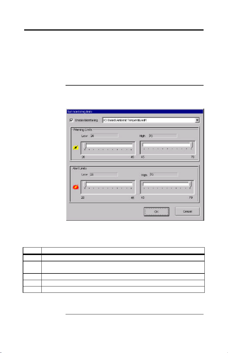
Quick Start, Continued
Setting Up the Health Information Group One of the most useful groups in
the ASM Console is the Health Information group. To use
ASM effectively, you must set this group up correctly. Click
on the Health Information icon in the top frame. This enables
the health buttons on the Toolbar. For more information
about the Toolbar icons, refer to page 113. The following
pages describe the Health Information procedures.
Setting Monitoring Limits Click on the Health Limits button on the toolbar
to bring up the "Set monitoring limits" window:
Use the following procedure to disable monitoring for any
health parameter that you do not want monitored, that is
not supported by the hardware, or that is not applicable.
Step Action
1 Click on the Health Information group. This enables the health buttons.
2 Click on the Health Limits button on the toolbar to bring up the Health
Limits window.
3 Select a parameter from the drop down menu.
4 Remove the check mark from the Enable Monitoring box.
5 Click OK when done.
To change the limits of any enabled parameter, select that
parameter and set the desired limits.
Chapter 4 AMI Server Manager Overview and Setup
Cont'd
85
Page 96
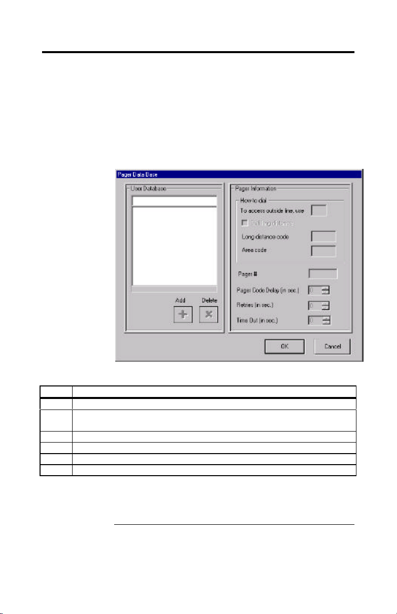
Quick Start, Continued
Setting Up Pager Database Options In order to use the pager feature, your
local machine must have a modem installed and correctly
set up in Windows. Also, it must be connected to an active
phone line.
If an alert or warning is issued, you can set up ASM
Console to dial a pager and enter a code to be displayed on
the pager. Click on the Pager Database button on the toolbar
to bring up the Pager Database screen.
Use the following procedure to set up the pager feature:
Step Action
1 Click on the Health Information group to enable the health buttons.
2 Click on the Pager Database button on the toolbar to open the Pager
Database window.
3 Enter the user name and pager information.
4 Click the Add button.
5 To add more users, enter their information, and click Add.
6 When all the users have been entered, click OK.
For more information on the Pager Database window, refer
to Pager Database in the online help or on page 113 of this
manual.
Megaplex Quad Pentium II Xeon PCI ISA System Guide
86
Cont'd
Page 97
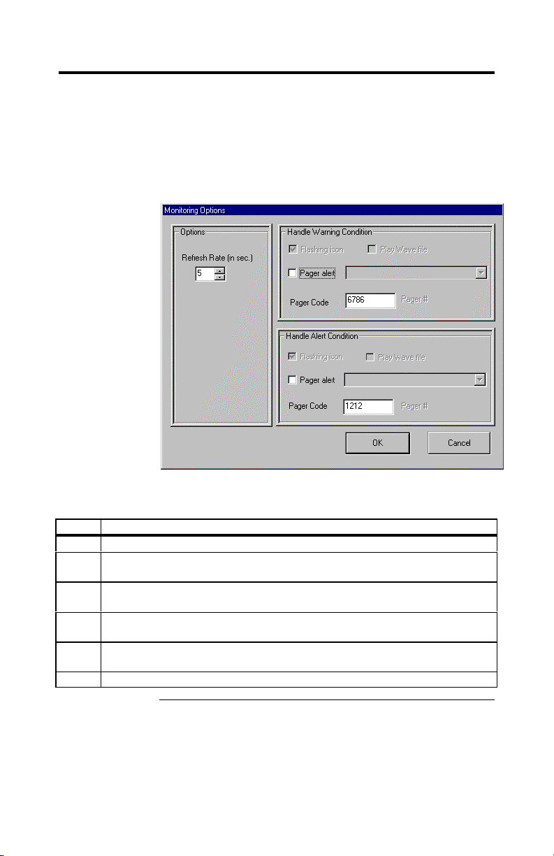
Quick Start, Continued
Setting Up Monitoring Options You can use the Monitoring Options
screen to choose how often the server health parameters
are checked, whether a pager alert should be sent, and how
to handle warning and alert conditions.
Click on the Health Options button on the toolbar to bring
up the Monitoring Options screen.
Use the following procedure to set up the monitoring
options:
Step Action
1 Click on the Health Information group to enable the health buttons.
2 Click on the Health Options button on the toolbar to open the Monitoring
Options window.
3 In the Options section, set how often you want the monitoring values to be
updated.
4 In the Handle Warning Condition section, select which user pager you
want to be dialed when a warning occurs, and the pager code.
5 In the Handle Warning Condition section, select which user pager you
want to be dialed when an alert occurs, and the pager code.
6 Click OK when done.
Chapter 4 AMI Server Manager Overview and Setup
87
Page 98

Installing AMI Server Manager
The user must be a member of the Administrators group in
User Manager to install AMI Server Manager. Refer to
Windows NT help for more information about User Manager.
Insert the ASM CD in the CD-ROM drive. Click on the
Start button and choose Run. Type
D:SETUP
and click on OK to install AMI Server Manager. Follow
the instructions on the screen. You will be asked for a
username and password. ASM agent uses this information
to control who can access ASM agent on that machine.
You can also select which components to install and when
you want ASM to be installed.
Note: If your CD-ROM is set up as a drive other than D,
replace D above with the drive letter your CD is assigned.
AMI Server Manager Setup
AMI Server Manager Agent Setup ASM Setup is used to install ASM
Agent. The Windows NT user installing Server Manager
must be a member of the Administrators group defined in
the User Manager. For more information about the User
Manager, refer to the Windows NT help.
During ASM installation, you are asked which components
you want to install. To install the ASM Agent, select the
AMI Server Manager Agent component. ASM Setup will
create an ASM Agent icon in the StartUp group on the
Start Menu. When installation is complete, ASM Setup
will need to restart your computer. Log on using an
account in the Administrators group. When you log on,
ASM Agent will start because it is in the StartUp group.
You can tell when the Agent is running by the AMI logo
(similar to a red triangle) visible on your system tray. This
is the Agent icon. To stop the Agent, double click the icon
and close the Agent window that appears. The Agent icon
will no longer be on the system tray.
If you want to start the ASM Agent, but do not see the
Agent icon on the system tray, go to the Start Menu and
select Programs, AMI Server Manager, and ASM Agent.
Megaplex Quad Pentium II Xeon PCI ISA System Guide
88
Cont'd
Page 99

AMI Server Manager Setup, Continued
AMI Server Manager Console Setup To start Console, click the Start icon,
and select Programs, AMI Server Manager, ASM Console.
If you installed the Console only or gave ASM
administrative privileges during installation, you will be
asked which machine you want to connect to. Select a
machine and click OK to load the console.
When ASM Console first loads, the System Inventory
group is selected. (For more information about System
Inventory, refer to page 98.) There are six icons on the
framebar, one for each information group. If an icon is
flashing, then there is a problem with that group. Click on
the icon to see what is wrong and take corrective action.
The rest of this chapter contains detailed information about
the icons.
Note: If this is your first time running AMI Server
Manager, please read the following section before you
respond to a flashing icon.
Health Information Group Setup The Health Information group is one of
the most useful groups in ASM Console. To use ASM
effectively, you must set this group up correctly. You can
disable monitored parameters, set up a pager database, and
set up monitoring options.
Click on the Health Information icon in the top frame. This
enables the health buttons on the Toolbar. For information
about the procedures listed above, refer to page 85.
Chapter 4 AMI Server Manager Overview and Setup
89
Page 100
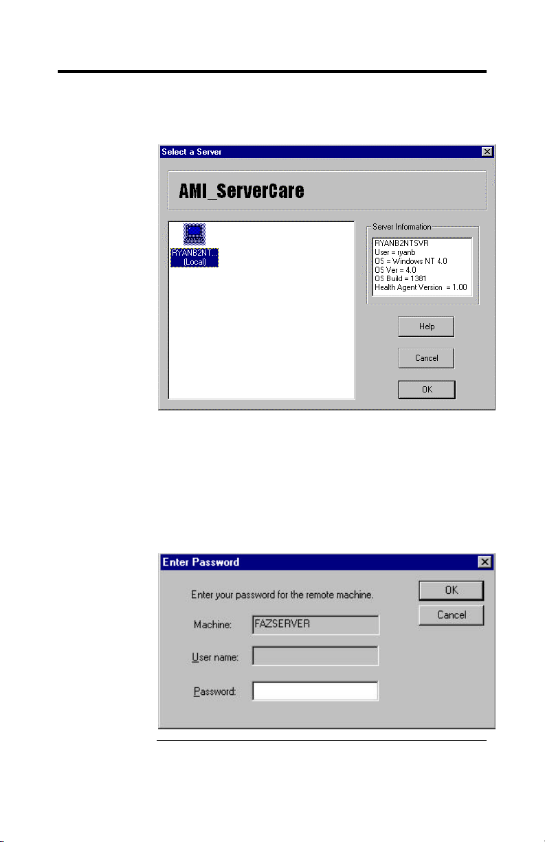
Selecting a Server
AMI Server Manager automatically detects all Megaplex
NT servers connected to the network. Icons for all servers are
displayed on the Server Selection screen, as shown below:
Click on a server icon to connect AMI Server Manager to
that server. You can perform any AMI Server Manager
function on the selected server after you have selected it.
You can also click on the Connect button on other AMI
Server Manager screens to connect to a different server.
If you set up a password during installation, the following
dialog box displays when you press OK:
Megaplex Quad Pentium II Xeon PCI ISA System Guide
90
 Loading...