

Page 1

Goliath PCI Quad
Pentium® Pro
EISA System
User's Guide
MAN-730
6/7/96
Page 2

© Copyright 1985-2010 American Megatrends, Inc.
All rights reserved.
American Megatrends, Inc.
5555 Oakbrook Parkway, Building 200,
Norcross, GA 30093
This publication contains proprietary information which is protected by copyright. No part of this publication may be reproduced, transcribed,
stored in a retrieval system, translated into any language or computer language, or transmitted in any form whatsoever without the prior written
consent of the publisher, American Megatrends, Inc.
Limited Warranty
Buyer agrees if this product proves to be defective, that American Megatrends, Inc. is only obligated to replace or refund the purchase price of this
product at American Megatrends’ discretion according to the terms and conditions on the warranty card. American Megatrends shall not be liable
in tort or contract for any loss or damage, direct, incidental or consequential. Please see the Warranty Registration Card shipped with this product
for full warranty details.
Limitations of Liability
In no event shall American Megatrends be held liable for any loss, expenses, or damages of any kind whatsoever, whether direct, indirect,
incidental, or consequential, arising from the design or use of this product or the support materials provided with the product.
Trademarks
Intel and Pentium Pro are registered trademarks of Intel Corporation.
MS-DOS, Microsoft Word, and Microsoft are registered trademarks of Microsoft Corporation. Microsoft Windows, Windows 95, and Windows
NT are trademarks of Microsoft Corporation.
SMC is a registered trademark of SMC Corporation.
IBM, AT, VGA, PS/2, OS/2, and EGA are registered trademarks of International Business Machines Corporation. XT and CGA are trademarks of
International Business Machines Corporation.
Fujitsu is a registered trademark of Fujitsu America, Inc.
Motorola is a registered trademark of Motorola Corporation.
Hitachi is a registered trademark of Hitachi America, Ltd.
PNY is a registered trademark of PNY Corporation.
Oki is a registered trademark of Oki America, Inc.
NEC is a registered trademark of NEC Corporation.
Samsung is a registered trademark of Samsung Electronics Corporation.
Siemens is a trademark of Siemens Corporation.
Mitsubishi is a registered trademark of Mitsubishi Electronics of America.
Micron is a registered trademark of Micron Corporation.
SCO, UnixWare, and Unix are registered trademarks of The Santa Cruz Operation, Inc..
Toshiba is a registered trademark of Kabushiki Kaisha Toshiba.
VESA is a trademark of the Video Electronics Standards Association.
All other brand and product names are trademarks or registered trademarks of their respective companies.
Revision History
5/19/96 Initial release.
6/7/96 Updated for new BIOS release.
Goliath PCI Pentium Pro EISA System User’s Guide
ii
Page 3

Preface
To the OEM Thank you for purchasing the high performance American Megatrends Goliath
EISA system. This product is a state of the art set of CPU cards, memory card,
and a baseboard that includes the famous AMIBIOS. It is assumed that you
have also licensed the rights to use the American Megatrends documentation
for the American Megatrends Goliath.
This manual was written for the OEM to assist in the proper installation and
operation of this product. This manual describes the specifications and features
of the Goliath system. It explains how to assemble a system based on the
Goliath system and how to use the AMIBIOS that is specifically designed for
this system.
This manual is not meant to be read by the computer owner who purchases a
computer with this system. It is assumed that you, the computer manufacturer,
will use this manual as a sourcebook of information, and that parts of this
manual will be included in the computer owner's manual.
Preface iii
Page 4

Technical Support
If you need help installing, configuring, or running this product, call American
Megatrends technical support at 770-246-8645. You can also send questions to
tech support at:
Goliath PCI Pentium Pro EISA System User’s Guide
iv
Page 5

Packing List
You should have received the following:
• a Goliath baseboard,
• a Series 731 CPU 1 card,
• a Series 732 CPU 2 card or a Series 733 terminator card,
• a Series 741 memory card,
• a U-shaped bracket with screws and spacers to be attached to the S730
• a customized PS/2 mouse cable,
• two customized serial cables,
• one customized parallel cable,
• a Warranty Card, and
• the American Megatrends Goliath Pentium Pro EISA System User's Guide.
Static Electricity
The Goliath baseboard, CPU cards, and memory card can easily be damaged by
static electricity. Make sure you take appropriate precautions against static
electric discharge:
• wear a properly-grounded wristband while handling the Goliath system or
• touch a grounded anti-static surface or a grounded metal fixture before
• handle system components by the mounting bracket, if possible.
baseboard, the CPU 2 card, and the memory card,
any other electrical component,
handling the Goliath system,
Batteries Make sure you dispose of used batteries according to the battery manufacturer’s
instructions. Improper use of batteries may cause an explosion. Make sure you
follow the battery manufacturer’s instructions about using the battery. Replace
used batteries with the same type of battery or an equivalent recommended by
the battery manufacturer.
Preface v
Page 6

1 Hardware Installation
Features
The American Megatrends Goliath Quad Pentium Pro™ EISA PCI system
supports one to four Intel® Pentium Pro CPUs operating at 180 MHz or higher
speeds.
Components The Goliath consists of several components:
• a baseboard that includes the EISA and PCI expansion slots and most of
the electronics,
• a primary and a secondary CPU Card. Each CPU Card can have 1 or 2
Pentium Pro CPUs,
• A Terminator Card (used only if the second CPU Card is not installed),
and a
• memory card.
The Goliath system was designed to run with the memory card and both CPU
Cards installed on the baseboard. However, the second CPU Card does not have
to be installed if a Series 733 GTL terminator is installed in J8, the CPU Card 2
connector.
CPUs The Pentium Pro CPUs are mounted on two separate CPU Cards for easy CPU
upgrades. Each CPU card holds one or two Pentium Pro CPUs. All Intel
Pentium Pro CPUs use 3.3V.
System Memory The Goliath system supports up to 1 GB of onboard system memory through
eight 8 DIMM sockets. This system supports four-way interleaved memory
operation for maximum performance. The system supports 168-pin DIMMs.
The system memory supports ECC (Error Checking and Correction).
Cont’d
Chapter 1 Hardware Installation
1
Page 7

Features, Continued
Cache Memory The Goliath system provides 256 KB or 512 KB of cache memory internal to
each Pentium Pro CPU.
EISA ExpansionThe Goliath baseboard includes four EISA expansion slots. All EISA expansion
slots can handle full-length EISA adapter cards.
PCI Local Bus The Goliath baseboard has six PCI expansion slots on two peer PCI buses using
dual OPBs (Orion PCI Bridge) and totally independent parallel PCI operation
on two peer PCI buses. The buses can transfer data simultaneously at a
maximum rate of 132 MBs.
All PCI slots are bus master slots and comply with the PCI Version 2.0
specification. All PCI expansion slots except the Primary PCI 3 slot can handle
full-length PCI adapter cards.
Integrated I/O The Goliath baseboard provides the following integrated I/O:
• one bidirectional parallel port that operates in Normal, EPP, or ECP mode,
• two serial ports with 16550A UARTs,
• one floppy drive controller with support for 360 KB, 720 KB, 1.2 MB, 1.44
MB, and 2.88 MB floppy drives,
• support for up to two Enhanced IDE drives on the PCI local bus,
• a berg header for a PS/2 mouse cable, and
• a standard DIN keyboard connector.
Cont’d
Goliath PCI Pentium Pro EISA System User’s Guide
2
Page 8

Features, Continued
Power Monitors The Goliath baseboard includes power monitor that make sure all power lines
are stable before the CPUs are started. The onboard voltage monitors check all
voltages and provide a warning if power is about to fail.
IDE Features IDE support on the Goliath baseboard includes:
• supports up to 2 IDE drives on the local bus,
• supports IDE programmed I/O (PIO) modes 3 and 4,
• provides bus mastering IDE support,
• provides IDE on the local bus,
• supports 32-bit data transfers,
• provides Fast ATA support, and
• supports LBA and Block Mode.
AMIBIOS AMIBIOS includes a PCI BIOS with WINBIOS Setup in flash ROM. Features
include:
• automatic CPU detection,
• Plug and Play NVRAM,
• PCI-PCI bridge support,
• DMI support,
• ATAPI support for IDE CD-ROM drives,
• ability to boot from a CD-ROM drive,
• complies with the Intel NSP specification,
• automatically detects IDE drive parameters,
• supports Enhanced IDE, including support for 2 IDE drives,
• supports ATA IDE mode programming,
• provides LBA and Block Mode support,
• provides boot sector virus protection,
• automatically detects and configures system memory, cache memory, and the CPU
type,
• automatically configures PCI devices, and
• complies with the Plug and Play Version 1.0A BIOS specification.
Cont’d
Chapter 1 Hardware Installation
3
Page 9
Features, Continued
PCI Bus Speed The Goliath system conforms to the PCI Version 2.0 specification. The PCI
slots are automatically configured by the AMIBIOS. The PCI slots operate
synchronously with the CPU clock, as follows:
CPU External Clock Frequency PCI Expansion Slot Frequency
66 MHz 33 MHz
60 MHz 30 MHz
Goliath Dimensions
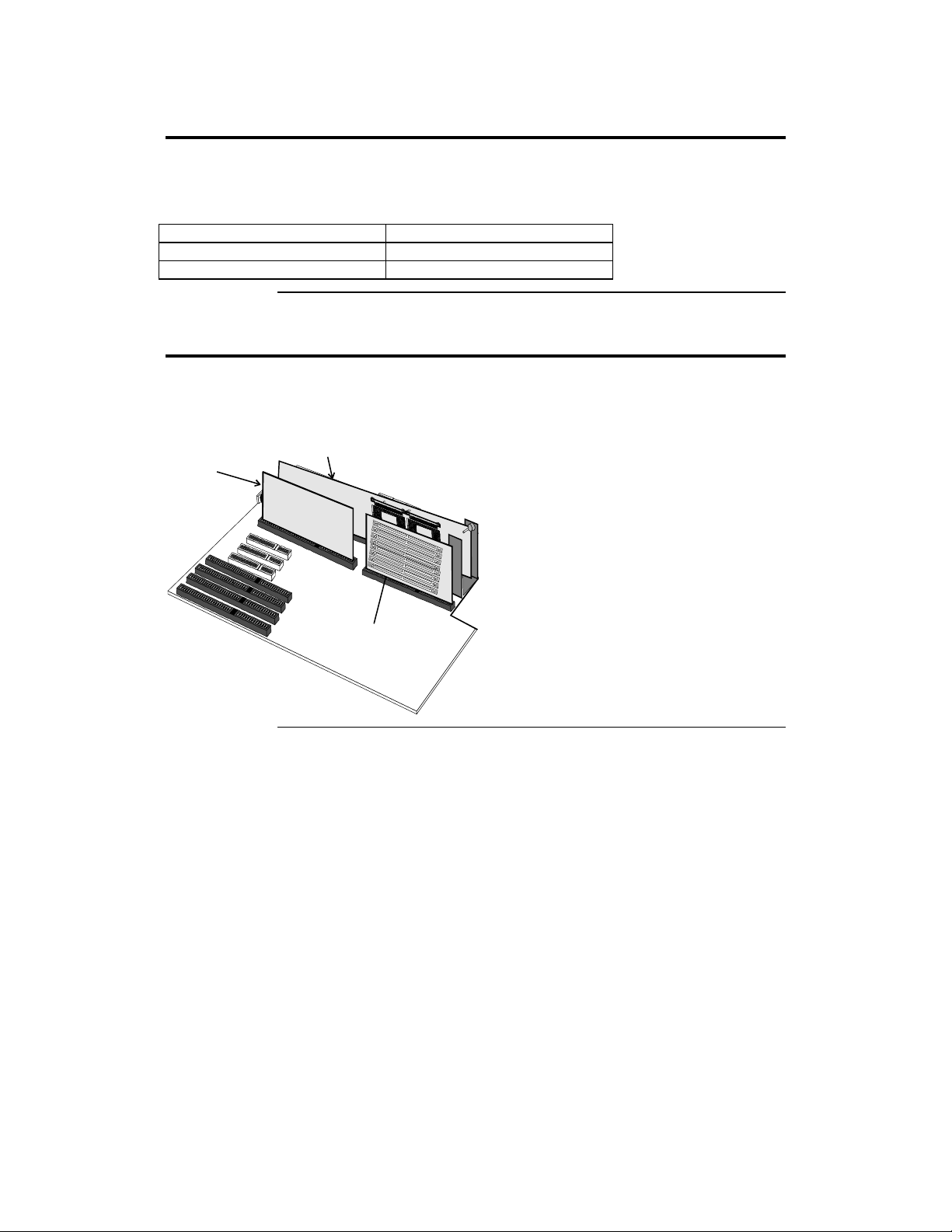
The full-size AT Goliath baseboard is approximately 12” by 13.1”. The Series
732 CPU Card 2 is 13” long and 6” high. The Series 731 CPU Card 1 is 7”
long by 6” high. The Series 741 Memory Card is 6.25” long and 6” high.
CPU Card 1
CPU Card 2
Bolt the Memory Card to the steel
bracket with a plastic spacer between
the bracket and the Memory Card.
Bolt the memory card
to the steel U bracket
with a plastic spacer
between the bracket
and the memory card.
Secure the U bracket to the
baseboard using the
screw and nut pair.
Memory Card
Goliath PCI Pentium Pro EISA System User’s Guide
4
Page 10
Installation Steps
Step Action
1 Unpack the baseboard and associated adapter cards.
2 Configure the CPU.
3 Install memory.
4 Install the baseboard.
5 Attach cables to connectors.
6 Connect the serial ports.
7 Connect the parallel port.
8 Connect floppy drives.
9 Connect the IDE drive(s).
10 Test and configure.
Configure the CPU.
Set the Clock Ratio.
Configure CPU Card 1.
Configure CPU Card 2.
Install the CPU.
Install system memory.
Connect the power supply.
Attach the keyboard cable.
Connect the mouse cable.
Attach connector cables.
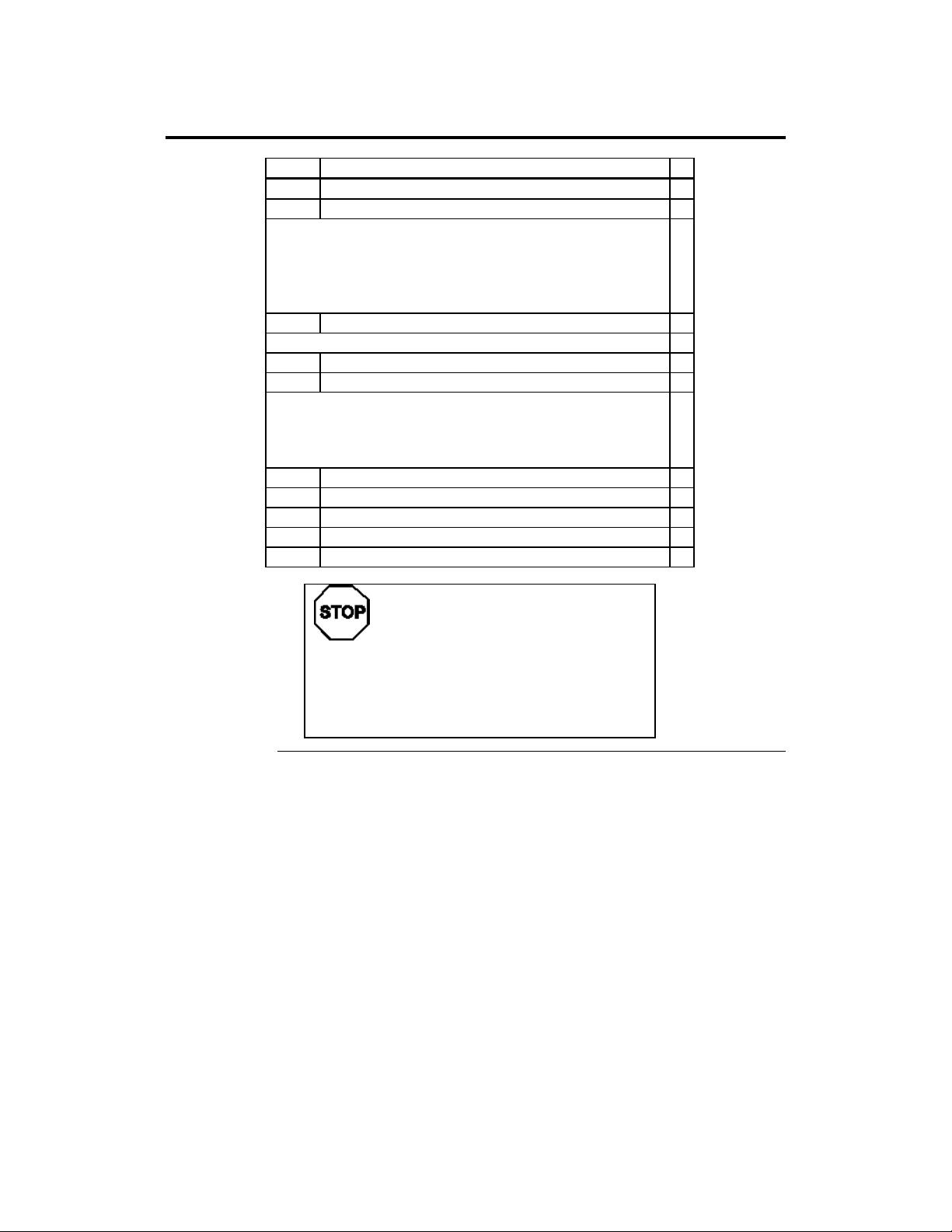
Warning
This baseboard contains sensitive electronic
components that can be easily damaged by static
electricity. Follow the instructions carefully to
ensure correct installation and to avoid static
damage.
Chapter 1 Hardware Installation
5
Page 11
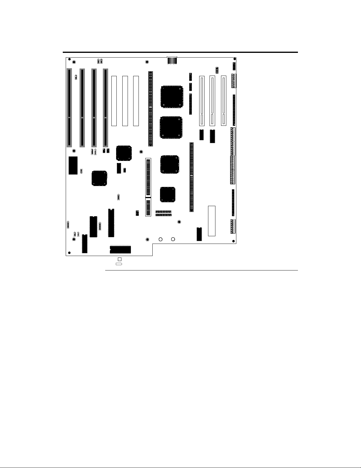
Goliath Baseboard Layout
5
The points toward Pin 1.
2
DE
J28
SPKR
J29
HLED
J26
Real Time Clock
J25
Ext
SMI
J27
RESET
J24
J21
J23
J22
KBD
Lock
J19
J20
J18
J17
PCI SLOT 4
J10 Mouse
J4
PCI SLOT 5
Series 730 Rev-C Goliath
(C) 1996 A merican Megatrends
P1
P2
P3
P4
J3
Floppy
P6
P
PCI SLOT 6
J
I
J9 KEBD
J5
P10 PCI SLOT 1
P10 PCI SLOT 2
P12 PCI SLOT 3
J16
J11
J15
J12
Ser1
J6
Ser2
J7
LPT1
The Denotes Pin 1 in Jumpers and Connectors.
Goliath PCI Pentium Pro EISA System User’s Guide
6
Page 12
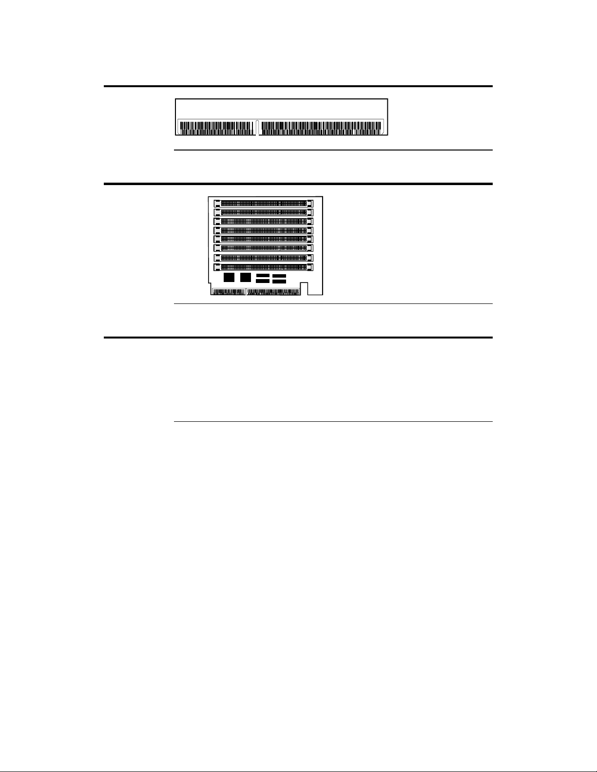
Goliath Terminator Card Layout
Goliath Memory Card Layout
DRAM Module1
DRAM Module2
DRAM Module3
DRAM Module4
DRAMModule5
DRAM Module6
DRAM Module7
DRAM Module8
Avoid Static Electricity
Static electricity can damage the baseboard and other computer components.
Keep the baseboard in the anti-static bag until it is to be installed. Wear an
anti-static wrist grounding strap before handling the baseboard. Make sure you
stand on an anti-static mat when handling the baseboard. Avoid contact with
any component or connector on any adapter card, printed circuit board, or
memory module. Handle these components by the mounting bracket.
Bank1
Bank2
Chapter 1 Hardware Installation
7
Page 13
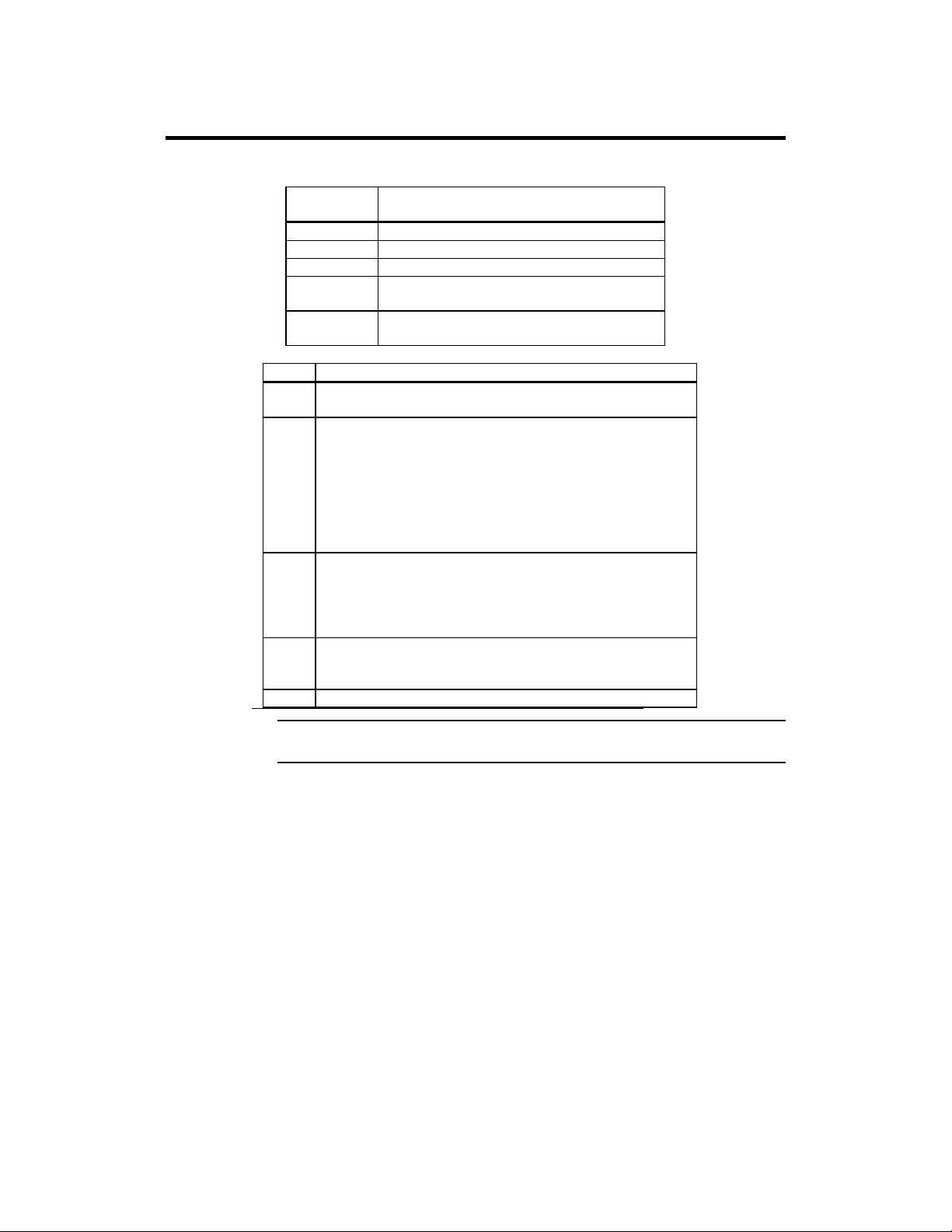
Step 1 Unpack the Boards
The Goliath system includes the following components:
AMI Part
Number
Series 730 Baseboard
Series 731 CPU I Card (has 1 or 2 Pentium Pro CPUs)
Series 732 CPU 2 Card (has 1 or 2 Pentium Pro CPUs)
Series 733 GTL terminator (only used if Series 732 CPU
2 Card is not installed)
Series 741 Memory Card (8 rows of DIMM DRAM
modules).
Step Action
1 Inspect the cardboard carton for obvious damage. If damaged,
call 770-246-8645. Leave the baseboard in its original packing.
2 Perform all unpacking and installation procedures on a ground-
connected anti-static mat. Wear an anti-static wristband
grounded at the same point as the anti-static mat. Or use a
sheet of conductive aluminum foil grounded through a 1
megohm resistor instead of the anti-static mat. Similarly, a
strip of conductive aluminum foil wrapped around the wrist
and grounded through a 1 megohm resistor serves the same
purpose as the wristband.
3 Inside the carton, the baseboard is packed in an anti-static bag,
and sandwiched between sheets of sponge. Remove the sponge
and the anti-static bag. Place the baseboard on a grounded
anti-static surface component side up. Save the original
packing material.
4 Inspect the baseboard for damage. Press down on all ICs
mounted in sockets to verify proper seating. Do not apply
power to the baseboard if it has been damaged.
5 If the baseboard is undamaged, it is ready to be installed.
Description
Set Jumpers Set all jumpers and install the CPU before placing the baseboard in the chassis.
Goliath PCI Pentium Pro EISA System User’s Guide
8
Page 14

Step 2 Configure CPU
Important
Perform the following steps to configure the
baseboard before installing a CPU.
Compatible Mode J4 is an eight-pin berg on the baseboard that sets the compatibility mode.
Leave J4 OPEN.
APIC Mode J17 is a 3-pin berg that sets the APIC (Advanced Programmable Interrupt
Controller) mode. Always Short Pins 2-3 of J17.
External Clock J16 is a 6-pin berg on the baseboard that sets the PCI external bus clock speed.
The primary and secondary PCI clock is set to 30 MHz or 33 MHz by a /2
synchronous divisor.
External
PCI Clock
Speed
60 MHz Short Pins 1-2
66 MHz Short Pins 3-4 200 MHz 33 MHz
J16 CPU Internal
Short Pins 5-6
Speed
150 MHz
180 MHz
Internal PCI
Speed
30 MHz
Cont’d
Chapter 1 Hardware Installation
9
Page 15

Step 2 Configure CPU, Continued
CPU Clock Ratio J15 is an 8-pin berg on the Series 730 baseboard that sets the CPU clock ratio
for the Series 731 CPU Card 1.
J190 is an 8-pin berg on the Series 730 baseboard that sets the CPU clock ratio
for the Series 732 CPU Card 2.
If two CPUs are installed on a CPU Card, the CPUs must operate at the same
speed.
In Rev C of the baseboard, CPU Card 1 and CPU Card 2 can be set to different
internal clock ratios.
J15 for CPU Card 1
J190 for CPU Card 2
Short Pins 1-2
Short Pins 3-4
Short Pins 5-6
Short Pins 7-8
Short Pins 1-2
Short Pins 3-4
Short Pins 5-6
Short Pins 1-2
Short Pins 3-4
Short Pins 5-6
Short Pins 1-2
Short Pins 3-4
Short Pins 7-8
Short Pins 1-2
Short Pins 3-4
Short Pins 3-4
Short Pins 5-6
Short Pins 7-8
Short Pins 3-4
Short Pins 5-6
Short Pins 3-4
Short Pins 7-8
Short Pins 3-4 11:2 60 MHz 325 MHz
Ratio External CPU
Speed
2:1 66 MHz 133 MHz
3:1 60 MHz 180 MHz
3:1 66 MHz 200 MHz
5:2 60 MHz 150 MHz
7:2 66 MHz 233 MHz
4:1 60 MHz 240 MHz
5:1 60 MHz 300 MHz
9:2 66 MHz 283 MHz
Internal CPU
Speed
Cont’d
Goliath PCI Pentium Pro EISA System User’s Guide
10
Page 16
Step 2 Configure CPU, Continued
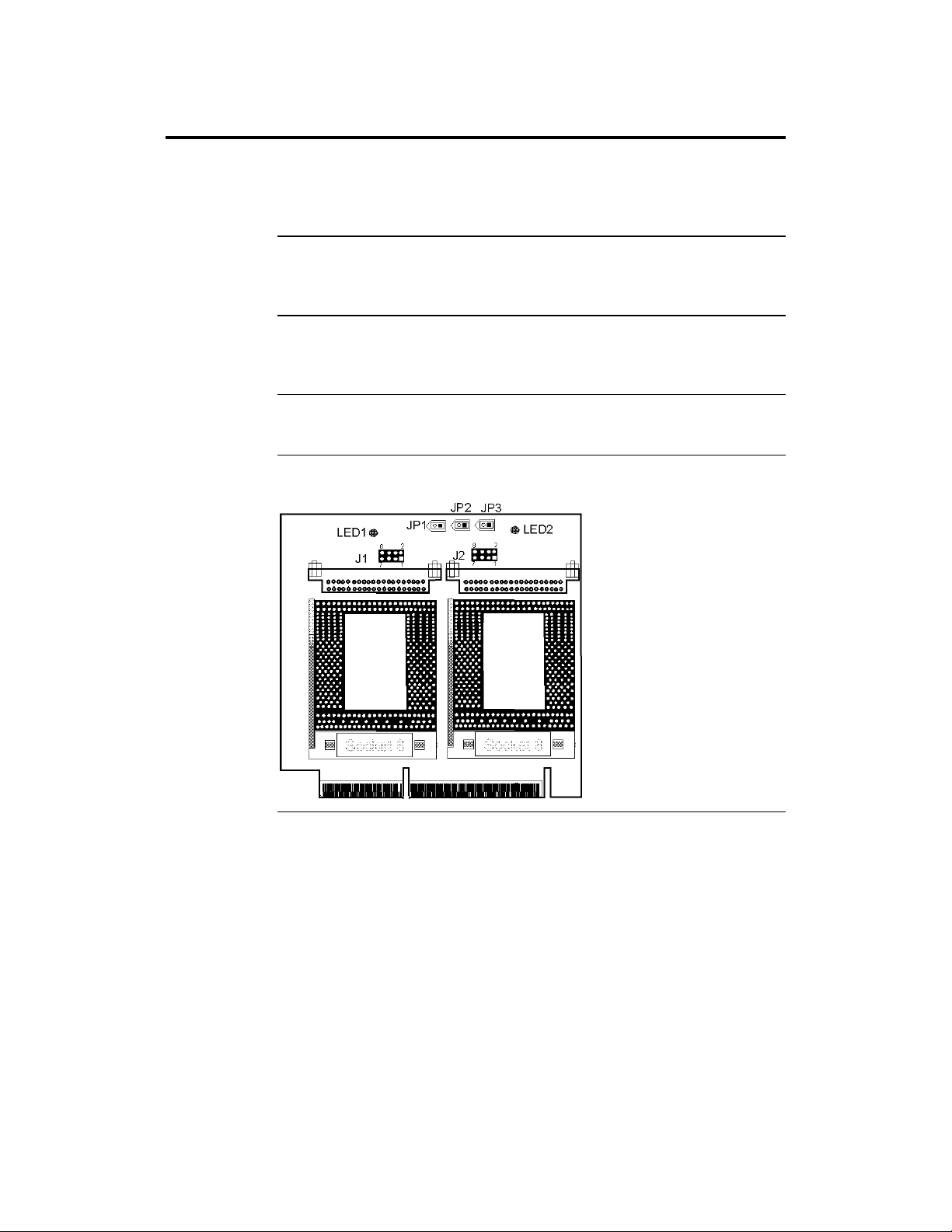
Configure CPU Card 1 You can install either one or two Pentium Pro CPUs in the ZIF sockets
on CPU Card 1. The CPU external and internal clock speeds are set via J15 on
the baseboard, as described on the previous screen. JP3 must always have a
shorting bridge.
Set VRM Output J1 on the CPU Cards set the VRM output for the first CPU. J2 sets the VRM
output for the second CPU. For a 3.3V CPU, short Pins 1-2, Pins 5-6, and Pins
7-8.
CPU Fans JP1 (for the first CPU) and JP2 (for the second CPU) are the +12V connectors
for the cooling fans. The CPU fan cable must be connected to one of these
connectors. Pin 1 of JP1 and JP2 is +12V. Pin 2 is Ground.
CPU Power Module The CPU Cards include two sockets for the two CPU power modules.
VRM8 is Voltage Regulator Module 8. VRM works from 5V input.
CPU Card Layout The CPU Card 1 layout is shown below.
Chapter 1 Hardware Installation
Cont’d
11
Page 17
Step 2 Configure CPU, Continued
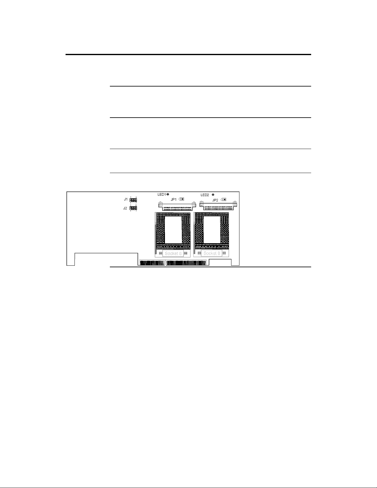
Configure CPU Card2 You can install either one or two Pentium Pro CPUs in the ZIF sockets
on CPU Card 2. The CPU external and internal clock speeds are set via J190 on
the baseboard. Both CPUs are configured in the same manner.
Set VRM Output J1 on the CPU Cards set the VRM output for the first CPU. J2 sets the VRM
output for the second CPU. For a 3.3V CPU, short Pins 1-2, Pins 5-6, and Pins
7-8.
CPU Fans JP1 (for the first CPU) and JP2 (for the second CPU) are the +12V connectors
for the cooling fans. The CPU fan cable must be connected to one of these
connectors. Pin 1 of JP1 and JP2 is +12V. Pin 2 is Ground.
CPU Power Module The CPU Cards include two sockets for the two CPU power modules.
VRM8 is Voltage Regulator Module 8. VRM works from 5V input.
CPU Card 2 Layout
Cont’d
Goliath PCI Pentium Pro EISA System User’s Guide
12
Page 18

Step 2 Configure CPU, Continued
JP3 This jumper on the Series 731 CPU Card 1 should always be shorted.
Overheat LEDs The Goliath CPU Cards have two red LEDs (one for each CPU) that indicate if
the CPU is overheating. A buzzer on the CPU Cards also sounds a warning if
the CPUs are overheating.
Important
Turn the computer off as soon as possible if an overheat
LED is lit. Operating the computer when this LED is on
can permanently damage the computer. Make sure that
the problem that caused the CPU to overheat is
corrected before you turn the computer on again.
The most frequent cause of overheating is a non-working CPU fan or a
disconnected CPU fan.
Install CPUs Install the Pentium Pro CPUs in the ZIF (zero insertion force) socket on the
CPU Card as shown below.
Do not install the CPU Card in the baseboard until after the CPUs are installed.
Both CPU Cards should be installed even if only one CPU Card includes a
mounted CPU. Each CPU Card can have either one or two Intel Pentium Pro
CPUs. Both CPUs on a CPU Card must run at the same frequency.
Warning
Improper CPU installation can damage the CPU,
the CPU Card, and the baseboard. You must
follow the procedures in this section exactly as
documented. Make sure you wear an antistatic
wristband while installing the CPU.
Cont’d
Chapter 1 Hardware Installation
13
Page 19
Step 2 Configure CPU, Continued
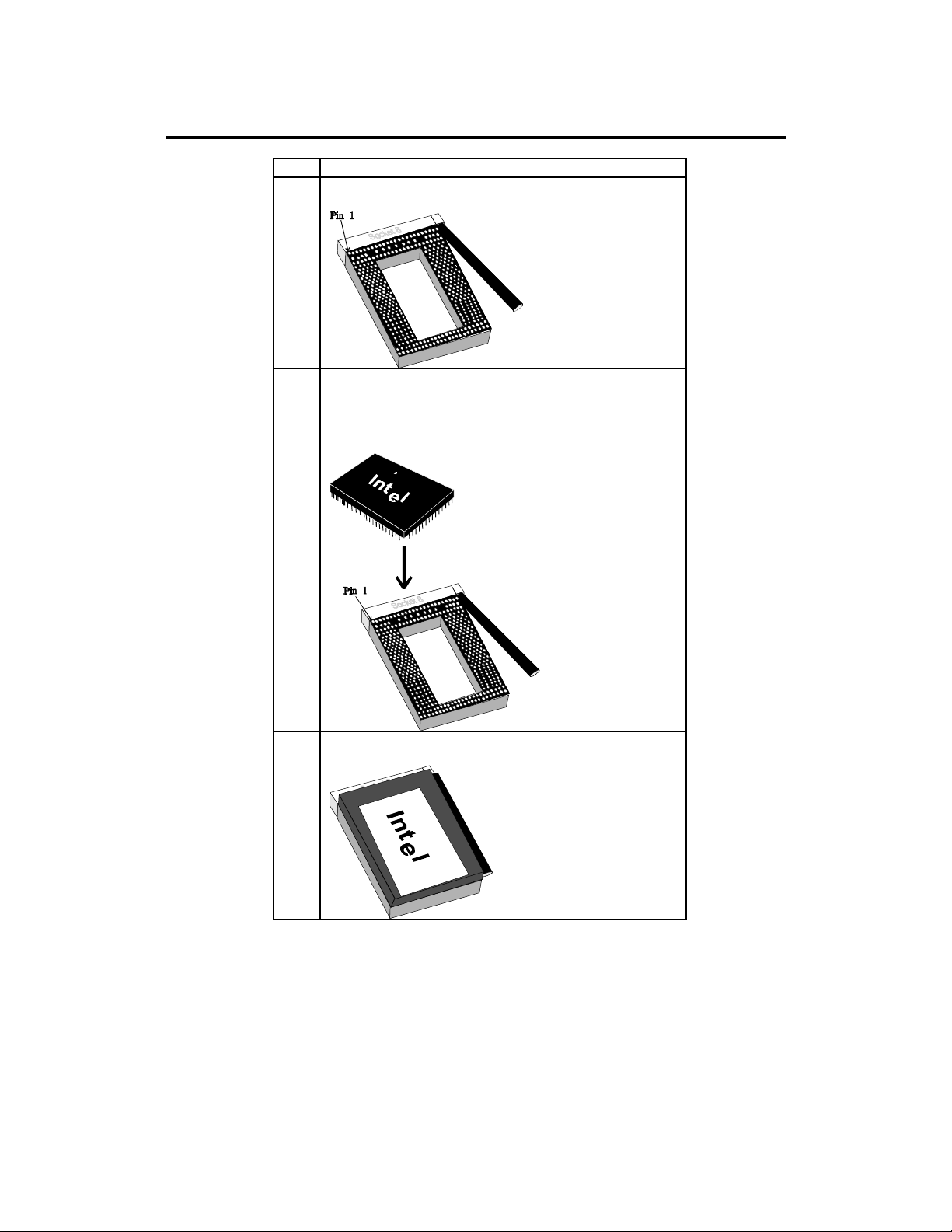
Step Action
1 Lift the lever on the ZIF socket. The empty CPU socket
looks like this.
2 Check for bent pins on the CPU. Gently straighten any bent
pins with pliers. Place the CPU in the middle of the socket,
as shown below. Make sure that pin 1 of the CPU is aligned
with pin 1 of the socket. Make sure you are properly
grounded while handling the CPU.
3 Lift the ZIF lever to the other side of the socket. Close the
handle until it latches.
Goliath PCI Pentium Pro EISA System User’s Guide
14
Page 20
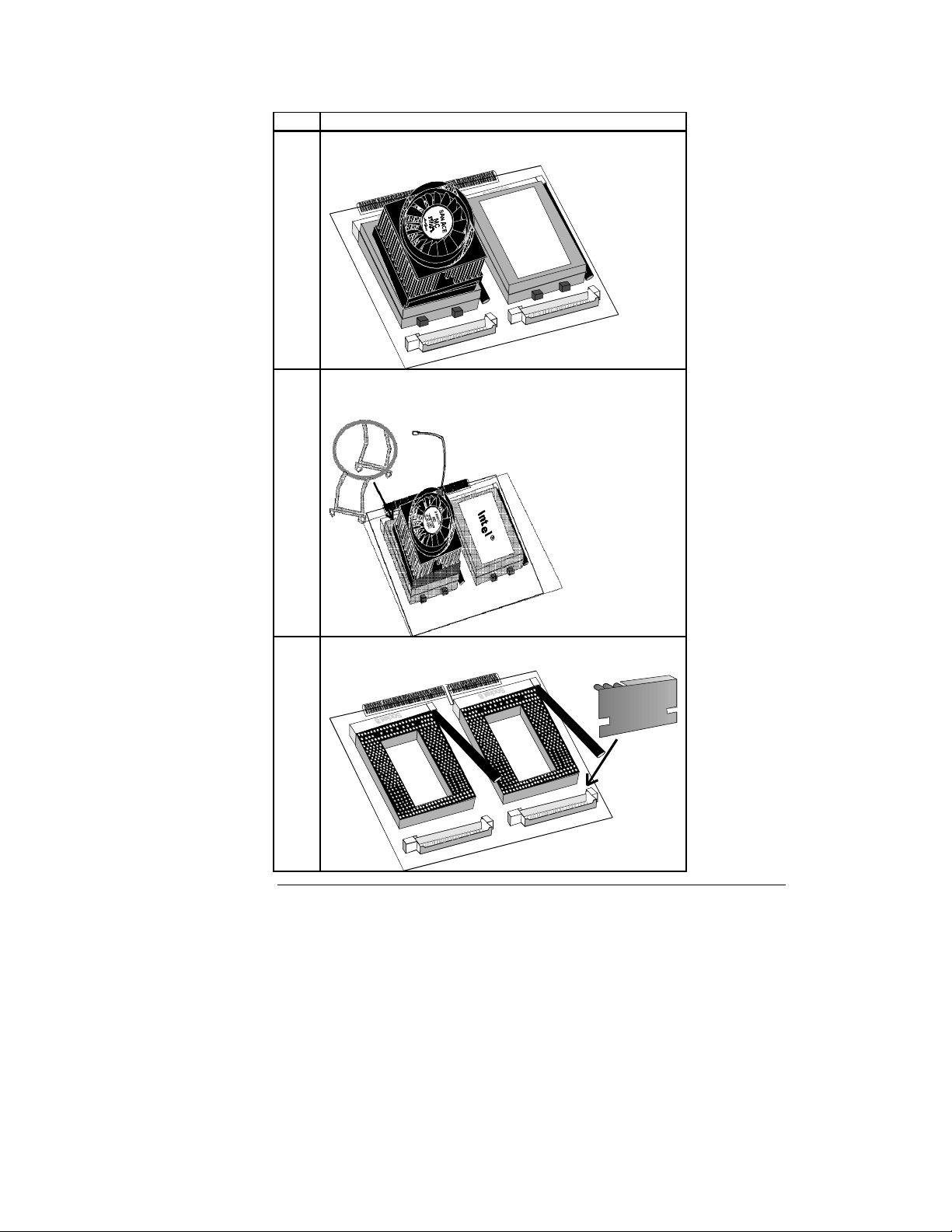
Step Action
4 Install the fan/heat sink and press down. The installed CPU
fan and heat sink will appear as follows.
I
n
t
I
n
t
e
l
u
5 Attach the fan cable to the appropriate fan connector (JP1 for
the first CPU or JP2 for the second CPU). Latch the CPU
clip on both sides to the tabs on the CPU socket.
e
l
u
6 Install the voltage regulator (VRM module) in the socket
above each installed CPU, as shown below:
Cont’d
Chapter 1 Hardware Installation
15
Page 21

Step 2 Configure CPU, Continued
Insert the CPU Cards in the baseboard after installing the baseboard in the
computer case.
Warning
Make sure that you insert and remove the CPU Cards vertically
in and out of the sockets. Do not move the CPU Cards from side
to side. Make sure the CPU Card is perpendicular to the base
board. Insert pressure directly downward when installing the
CPU Cards. When removing a CPU Card, pull the card straight
up. Do not move it from side to side.
Using One CPU Card If installing CPU Card 1 only, insert the Terminator Card in the CPU
Card 2 socket. Do not use CPU Card 2 alone.
Step 3 Install Memory
System Memory System memory for the Goliath is mounted on the memory card, which
supports up to 1 GB of system memory. Use 60 ns Fast Page ECC 3.3V 168-pin
ECC buffered memory module fast page mode or EDO DIMMs (Dual Inline
Memory Modules). The memory card has eight 168-pin sockets.
Set DRAM Voltage J11 and J12 are 20-pin jumpers that set the DRAM voltage. Only 3.3V
memory can be used.
Type of Memory J11 J12
3.3V 60 ns
Fast Page Mode
(or EDO)
x 72 ECC
Buffered Memory
Module DIMMs
Short Pins 1-2
Short Pins 3-4
Short Pins 5-6
Short Pins 7-8
Short Pins 9-10
Short Pins 11-12
Short Pins 13-14
Short Pins 15-16
Short Pins 17-18
Short Pins 19-20
All OPEN
Cont’d
Goliath PCI Pentium Pro EISA System User’s Guide
16
Page 22

Step 3 Install Memory, Continued
The DIMMs in Goliath are different from the x 36 SIMMs used by all other
boards. The memory modules in the Goliath are a new JEDEC-standard
defined for 8-byte wide common CAS memory and supported by most memory
manufacturers. Most new computers that require a large amount of memory
(such as servers) use DIMMs. The maximum DIMM height should be 1.5” so
PCI slots are not blocked.
Memory Specifications
Item Description
General 3.3 volt, 168 pin, x 72, ECC DIMM (Dual Inline Memory Module)
buffered memory module, fast page mode (or EDO), 60 ns.
Voltage The memory chips used on the module must be 3.3 volt parts.
Pinout The module pinout is 168 pin (instead of 72 pins on SIMMs).
Data Bits The memory modules are 72 data bit modules
No ECC It is “raw” single CAS DRAM. There is NO ECC logic on the memory
module. ECC (Error Correction Code) is implemented in the
motherboard chipset. ECC does not require parity chips.
Buffers 3.3V volt buffers (typically 163244 or 16244LVT) are used to buffer the
CAS, Address lines, and Write enables.
The x 72 ECC modules are buffered. The Goliath memory card cannot
use unbuffered memory modules.
Mode Goliath uses fast page mode modules. EDO (Extended Data Out) is a
superset of fast page mode. EDO memory modules can be installed, but
the EDO feature is not used.
DIMM Types 1 MBx72, 2 MBx72, 4 MBx72, 8 MBx72, and 16 MBx72.
Speed 60 ns
Maximum Memory Up to eight DIMMs can be installed to provide up to 1GB of system
memory. The minimum memory configuration should be 4 MB x 72 DIMMs
(128 MB of system memory). You cannot mix memory types within a memory
bank.
Cont’d
Chapter 1 Hardware Installation
17
Page 23

Step 3 Install Memory, Continued
DIMM Manufacturer’s Part Numbers
Type Manufacturer Part Number
2 MB x 72 3.3V Micron MT9LD272G-60
ECC FPM (16 MB) Micron MT9LD272G-60X (EDO)
Advantage A16/ECCDIMM
Samsung KMM372V213AJ6
4 MB x 72 3.3V Micron MT18LD472G-60
ECC FPM (32 MB) Micron MT18LD472G-60X (EDO)
Advantage A32ECCDIMM
Samsung KMM372V400AK6
Samsung KMM372F400AK6 (EDO)
8 MB x 72 3.3V Micron MT36LD872G-60 (FPM),
ECC FPM (64 MB) Micron MT36LD872G-60X (EDO)
Advantage A64/ECCDIMM
Samsung KMM372V803J6/AJ6
16 MB x 72 3.3V Advantage A128ECCDIMM
ECC FPM IBM 11M16730CBD
(128 MB) Samsung KMM372V1680J6
Samsung KMM372V1680AJ6
IBM 11M2730HBE
IBM 11M4730CBD
NEC MC-424000LAB72
IBM 11M8730CBD
Memory Suppliers
Company Contact Phone Fax
Advantage
Memory Corp.
Centon Paul Kindley,
Samsung Greg Mordecai 770-447-6154 770-447-6714
Netmemory John Deters 714 631 5388 714 631 8724
Dwayne Abrades 800 245 5299 714 453 8158
714 855 9111 714 855 1144
Steve Rick
Also contact Micron, IBM, or Hitachi. American Megatrends will supply
additional part numbers as they become available. The NRC part numbers may
not be complete. The DIMM parts listed above have not been tested. Check the
manufacturer’s specifications carefully before using any DIMM.
Cont’d
Goliath PCI Pentium Pro EISA System User’s Guide
18
Page 24

Step 3 Install Memory, Continued
DRAM Specifications The total amount of system memory is automatically detected by
AMIBIOS. System memory is four-way interleaved (if there are four or eight
DIMMs). The interleave factor is 2 if only two DIMM modules are installed.
Populate system memory 4 DIMMs at a time for maximum performance. A
memory bank must have either 1, 2, or 4 DIMMs installed in it.
DRAM system memory must be populated one bank at a time. All DIMMs in a
bank must be of the same memory type. Each socket can hold one DIMM. You
can use:
• 1 MB x 72,
• 2 MB x 72,
• 4 MB x 72,
• 8 MB x 72, or
• 16 MB x 72 DIMMs.
Memory Display System memory is reported by AMIBIOS as it boots and again when
the AMIBIOS System Configuration Screen is displayed just before the
operating system boots. The memory displayed by AMIBIOS on the System
Configuration Screen is 384 KB less than the total memory installed.
Cont’d
Chapter 1 Hardware Installation
19
Page 25

Step 3 Install Memory, Continued
Select DIMMs DIMMs must meet the following specifications:
Parameter Specification
Page Mode FAST Page Mode
Refresh CAS before RAS
t
CAC
t
RAC
t
AA
t
RP
t
CPA
DRAM Configurations Valid memory configurations include:
U8 U7 U6 U5 U4 U3 U2 U1 RAM
None None None None None None None 2 MB 16 MB
None None None None None None 2 MB 2 MB 32 MB
None None None None 2 MB 2 MB 2 MB 2 MB 64 MB*
None None None 2 MB None None None 2 MB 32 MB
None None 2 MB 2 MB None None 2 MB 2 MB 64 MB
2 MB 2 MB 2 MB 2 MB 2 MB 2 MB 2 MB 2 MB 128 MB*
None None None None None None None 1 MB 8 MB
None None None None 1MB 1MB 1 MB 1 MB 32 MB*
1 MB 1 MB 1 MB 1 MB 1 MB 1 MB 1 MB 1 MB 64 MB*
None None None None None None None 4 MB 32 MB
None None None None 4MB 4MB 4 MB 4 MB 128 MB*
4 MB 4 MB 4 MB 4 MB 4 MB 4 MB 4 MB 4 MB 256 MB*
None None None None None None None 16 MB 128 MB
None None None None 16 MB 16
16 MB 16 MB 16 MB 16 MB 16 MB 16 MB 16 MB 16 MB 1 GB*
Bank1 Bank0 Total
MB
*: four-way interleave configurations
≤ 20 ns
≤ 60 ns
≤ 45 ns
70 ns
≤ 45 ns
16 MB 16 MB 512 MB*
Cont’d
Goliath PCI Pentium Pro EISA System User’s Guide
20
Page 26
Step 3 Install Memory, Continued
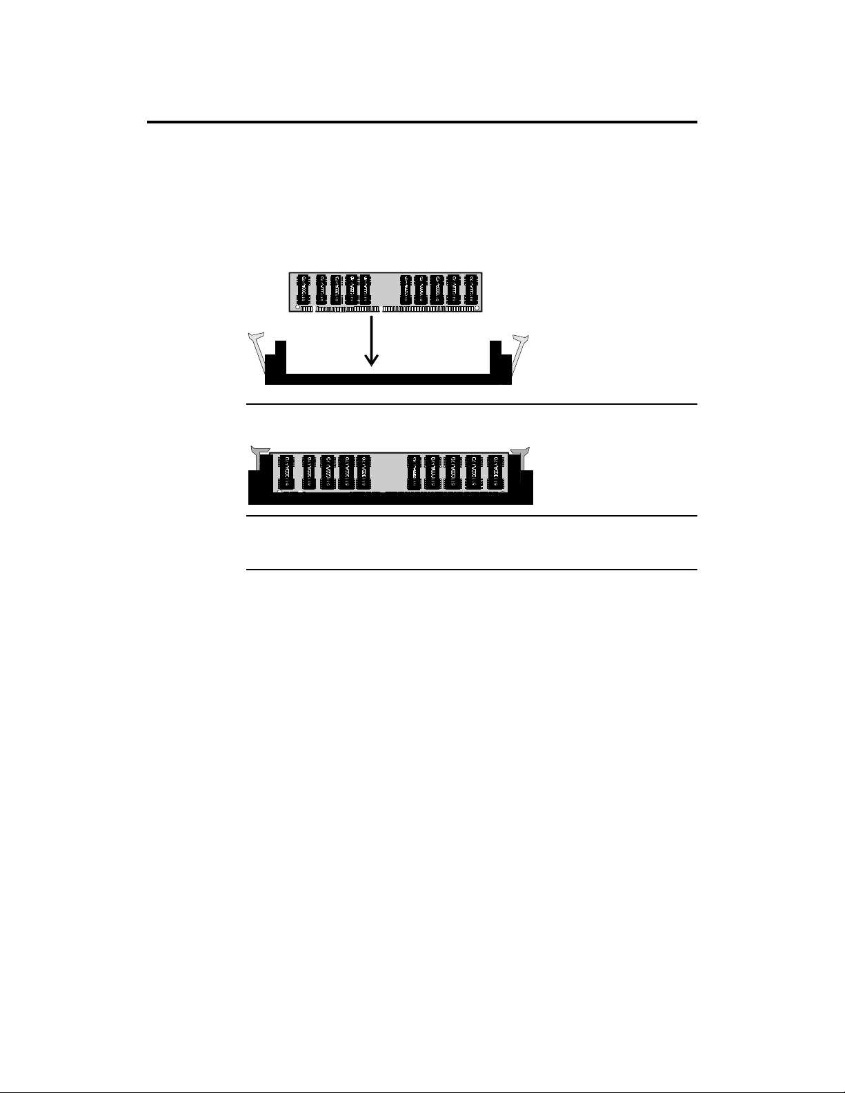
Installing DIMMs The Series 741 Memory Card has eight x 72 DIMM sockets. These sockets
can be filled with either 1 MB x 72, 2 MB x 72, 4 MB x 72, 8 MB x 72, or 16
MB x 72 DIMMs.
Place the Memory Card on an anti-static mat. Each of the 8 DIMM sockets has
a latch on either end. Make sure all DIM latches are fully open. With the
component side of the DIMM facing you, insert the DIMM into the socket and
secure the latches on either end of the DIMM, as shown below:
DIMM with Latches Secured
Install Memory Card Insert the Memory Card in the baseboard after installing the baseboard in
the computer case
Chapter 1 Hardware Installation
21
Page 27
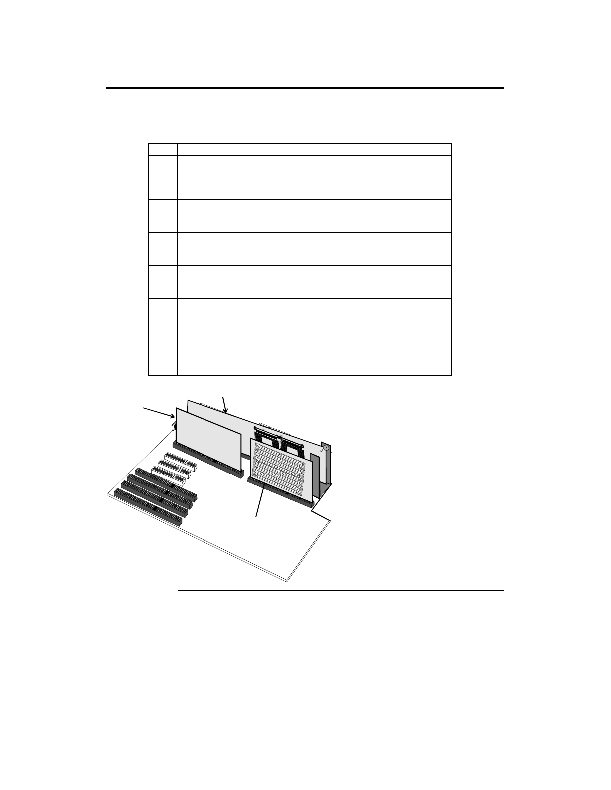
Step 4 Install the Baseboard
The baseboard mounting hole pattern is the same as the mounting hole pattern
on the standard full-size AT baseboard. The chassis manufacturer should
supply standoffs and screws.
Step Action
1 Place the chassis on an anti-static mat. Connect the chassis to ground to
avoid static damage during installation. Connect an alligator clip with a
wire lead to any unpainted part of the chassis. Ground the other end of
the lead at the same point as the mat and the wristband.
2 Rotate the chassis so the front is to the right. The side facing you is
where the baseboard is mounted. The power supply is mounted at the
far end of the chassis.
3 Hold the baseboard, component-side up, with the edge with the power
supply connector away from you. The keyboard and mouse should be to
the left.
4 Carefully slide the baseboard into the chassis. Make certain the edge
connectors fit the ports in the rear of the chassis. The baseboard should
rest level with the chassis.
5 Mount CPU 1, CPU 2 and memory cards in their sockets. Fasten the
brackets on the Series 731 and 732 cards to the back of the chassis.
Fasten a U-bracket between the Series 732 card and the memory card.
See below.
6 Align the mounting holes on the baseboard with the holes on the
chassis. Place the mounting screws in the holes provided and tighten
them.
CPU Card 1
CPU Card 2
Memory Card
Bolt the Memory Card to the steel
bracket with a plastic spacer between
the bracket and the Memory Card.
Bolt the memory card
to the steel U bracket
with a plastic spacer
between the bracket
and the memory card.
Secure the U bracket to the
baseboard using the
screw and nut pair.
Cont’d
Goliath PCI Pentium Pro EISA System User’s Guide
22
Page 28
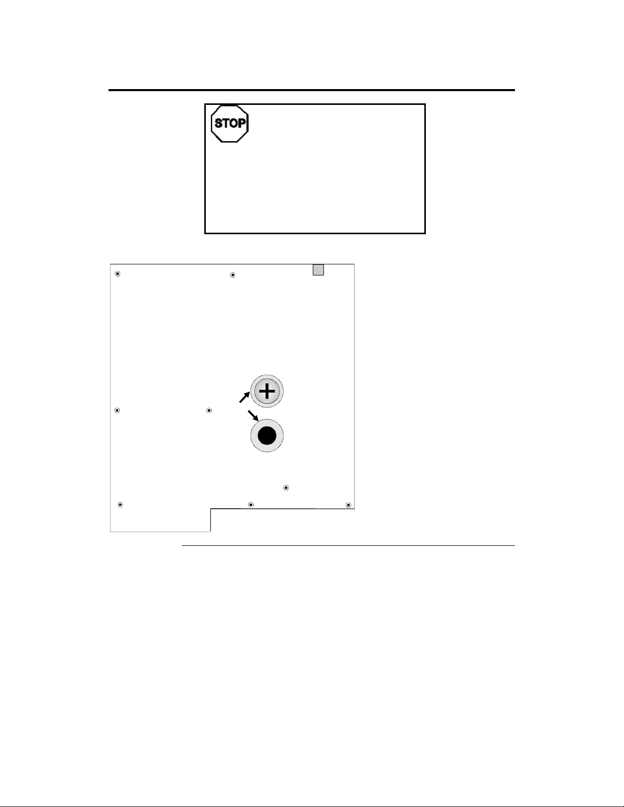
Step 4 Install Baseboard, Continued
If using metallic screws, make sure you use them
only in the plated mounting holes. If using
metallic screws, make sure the head of the screw
fits completely inside the plated mounting holes.
See the following graphic.
The screw head must not be
larger than the plating
around the mounting hole.
Warning
Plating
Chapter 1 Hardware Installation
23
Page 29
Step 5 Attach Power Supply
Connect Power The power supply should match the physical configuration of the chassis. Make
sure that the power switch is Off before assembly. Before attaching all
components, make sure that the proper voltage has been selected. Power
supplies often can run on a wide range of voltages and must be set (usually via
a switch) to the proper range. Power supplies are discussed below.
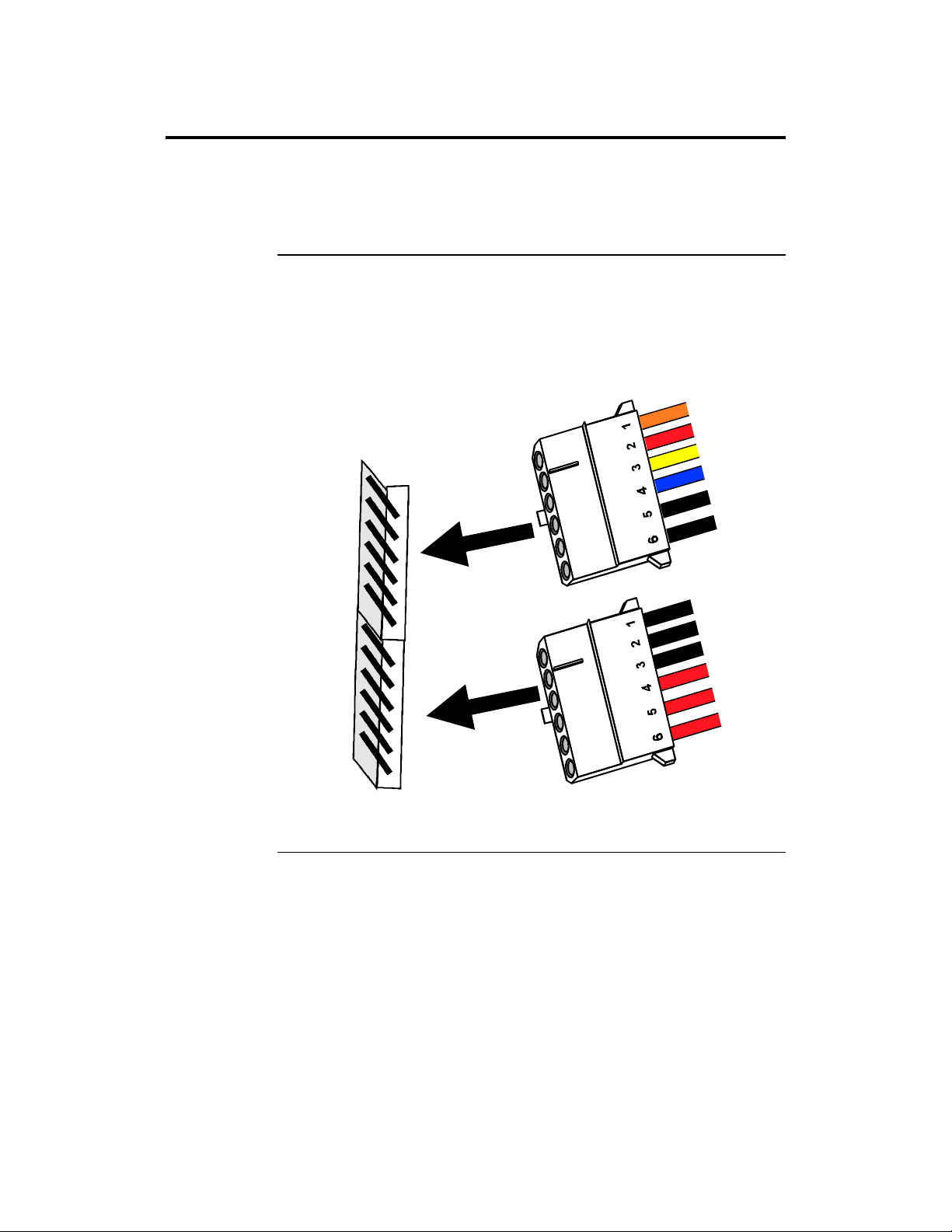
Power Cables Attach the power supply cables to the P3 and P4 power connectors on the
baseboard. AT-compatible power supplies have two 6-pin power connectors, as
shown below. The power supply manufacturers may have specific names like
P8 and P9. Be aware of this when you discuss the connectors required. The P1,
P2, P5, and P6 connectors are described below.
G
N
A
R
O
D
E
Pin 1
R
Y
B
B
E
B
O
L
L
E
U
L
C
A
L
A
L
P3
C
E
W
K
K
P4
Pin 1
B
B
B
A
L
L
L
R
R
R
K
C
K
C
A
C
A
D
E
D
E
D
E
Cont’d
K
Goliath PCI Pentium Pro EISA System User’s Guide
24
Page 30

Step 6 Attach Power Supply, Continued
Goliath uses a 3.3 volt AT power supply. There are six power connectors on the
base board. The power pin voltages are written on the base board silk screen.
Check the top of the base board. The 3.3V P1 and P2 pinouts are exactly
opposite of the +5V P5 and P6 pinouts. P1 or P2 must be connected before you
can power up. P3 and P4 are standard AT 6-pin power connectors. P3 and P4
are keyed to prevent incorrect installation.
The power requirements are unique for each system. Both +5V and +3.3V
power is usually required.
+5V Power Required For each Pentium Pro processor that is installed, an additional 8A +5 volt
is required. If four Pentium Pro CPUs are installed, 32A are required on +5V
for the processors alone. Also each EISA and PCI adapter card that is installed
requires power, usually 2.5A on +5V. Add the power required for all installed
CPUs and installed adapter cards. Check the electrical specification for each
adapter card for the power requirements. Make sure you check the power
requirements for all drives. The base board needs 5A on the +5 volt for board
electronics.
+3.3V Power Required The base board has 3.3V logic. The DRAM memory card also has 3.3V
logic. The base board requires 6A on +3.3V for the logic. 16 MB x 72 DRAM
modules usually requires 2.2A each. The maximum number of DRAM modules
is eight. Up to 17.6A may be needed for system memory. The total +3.3V
power requirement can be up to 25A.
+12V Power Required The Goliath base board and fans use 0.5A. There is no special
requirement, but +12V must be present as per the AT power supply
specification.
Cont’d
Chapter 1 Hardware Installation
25
Page 31

Step 5 Attach Power Supply, Continued
Total Power Required A minimum power requirement would be a 450 watts power supply with
50A on +5V and 25A on +3.3V. The power connector pins are rated for 6A. At
least one each of P5/P6 and P1/P2 is required. P3 and P4 must be connected.
Power Supply An L-shaped AT power supply with maximum dimensions of 8.6” x 5.4” x 5.9”
is required. An AC switch cable to the front panel is required . The base board
does not support remote sensing. The L-shaped power supply is specified for a
standard chassis. Other shapes and sizes can be used as per the customer
chassis requirements.
Power Cables The power cables should be 24 inches or longer, with the power outputs length-
compensated. The cable lengths are specified as a general guideline only. The
standard 18 inch cables will be short in a larger chassis.
Power Supply Vendors
Supplier Model Contact Phone Fax
Antec RPS 6002 * Frank Fu 510 770 1200 510-770-1288
Astec SA451-3500 ** Sales 619 757 1880 619 439 4243
PC Power &
Cooling
Senstron APA-5400F Dr Sing Hung 908 417 0411 908 417 0422
Tri Mag BM 7500 Sales 209 651 2222 209 651 0188
Turbo cool 3.3 T45G Larry Aldridge 800 722 6555 619 931 6988
* The Antec RPS6002 is larger than a standard L-shaped AT power supply. Antec has
other products.
** The Astec 451-3500 has an AC switch, no front panel cable, and needs remote sensing.
Some of the above models have lower +12V ampere rating than standard 450W
power supplies. Make sure the power supply meets your system’s power
requirements.
Cont’d
Goliath PCI Pentium Pro EISA System User’s Guide
26
Page 32
Step 5 Attach Power Supply, Continued
Power Supply Summary You must determine if a power supply meets your electrical and
mechanical requirements. This discussion is only a guideline. You must
perform the power calculation for your system. You can always use a different
power supply for drives. Redundancy and hot swap are system- and customerdependent, not basic requirements.
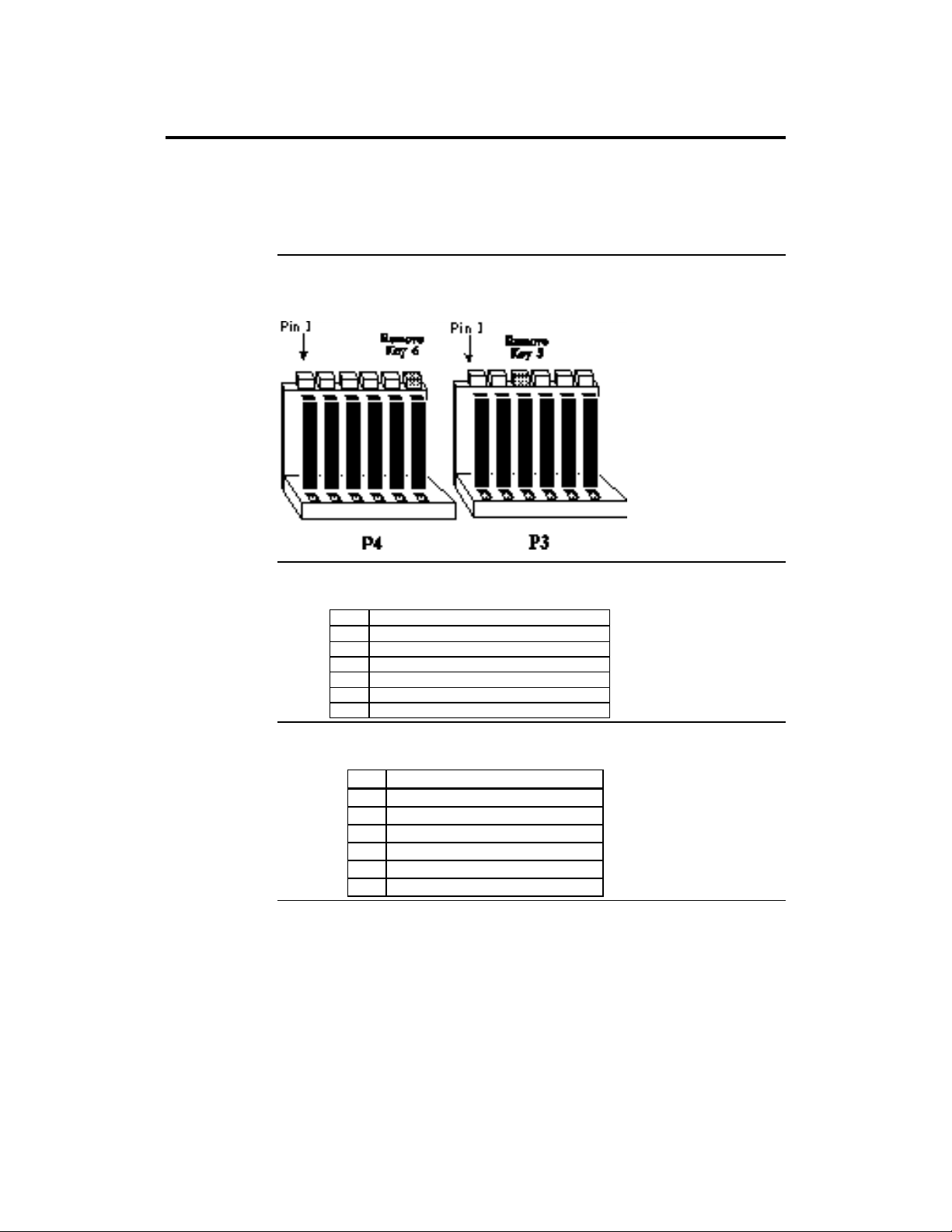
Connector Keys The keys on the connector must be cut to fit on some power supplies, as shown
below.
P3 Pinout
P4 Pinout
Pin Description
1 Power Good (Orange wire) (Not used)
2 VCC (Red wire)
3 +12 Volts (Yellow wire)
4 -12 Volts (Blue wire)
5 Ground (Black wire)
6 Ground (Black wire)
Pin Description
Ground (Black wire)
1
Ground (Black wire)
2
-5 Volts (White wire)
3
VCC (Red wire)
4
VCC (Red wire)
5
VCC (Red wire)
6
Chapter 1 Hardware Installation
27
Page 33
Step 5 Attach Power Supply, Continued
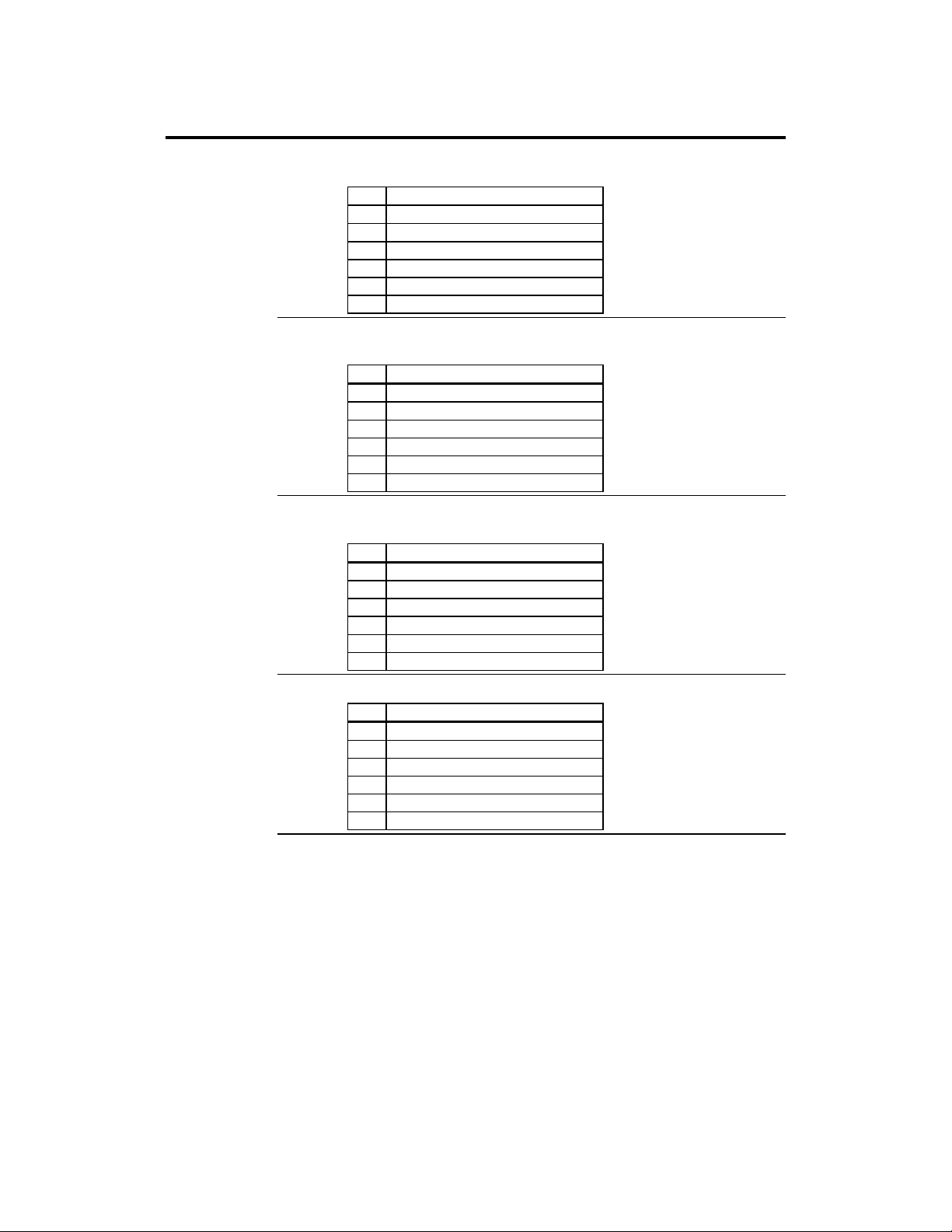
P1 Pinout P1 and P2 provide a 3.3V power source.
Pin Description
Ground (Black wire)
1
Ground (Black wire)
2
Ground (Black wire)
3
3.3V (Brown wire)
4
3.3V (Brown wire)
5
3.3V (Brown wire)
6
P2 Pinout
Pin Description
Ground (Black wire)
1
Ground (Black wire)
2
Ground (Black wire)
3
3.3V (Brown wire)
4
3.3V (Brown wire)
5
3.3V (Brown wire)
6
P5 Pinout P5 and P6 provide 5V power for additional drives.
Pin Description
5V (Red wire)
1
5V (Red wire)
2
5V (Red wire)
3
Ground (Black wire)
4
Ground (Black wire)
5
Ground (Black wire)
6
P6 Pinout
Pin Description
5V (Red wire)
1
5V (Red wire)
2
5V (Red wire)
3
Ground (Black wire)
4
Ground (Black wire)
5
Ground (Black wire)
6
Goliath PCI Pentium Pro EISA System User’s Guide
28
Page 34
Step 6 Attach Connectors
Connectors The Goliath baseboard includes many connectors. Connection instructions,
illustrations of connectors, and pinouts are supplied below. The Goliath
baseboard connectors are:
Connector
Keyboard connector J9
Mouse connector J10
Reset switch J27
Speaker J28
Keyboard lock connector J22
IDE LED connector J29
Serial port connectors J5 and J6
Parallel port connector J7
Floppy connector J3
IDE drive connector J2
Cable Connector Ends When connecting chassis connectors to the baseboard, make sure to
connect the correct connector end. Most connector wires are color-coded.
Match the color of the wires leaving the switch or LED to the same pin on the
connector end. There may be more than one connector with the same colorcoded wires. If so, follow the wire to the switch or LED. All baseboard
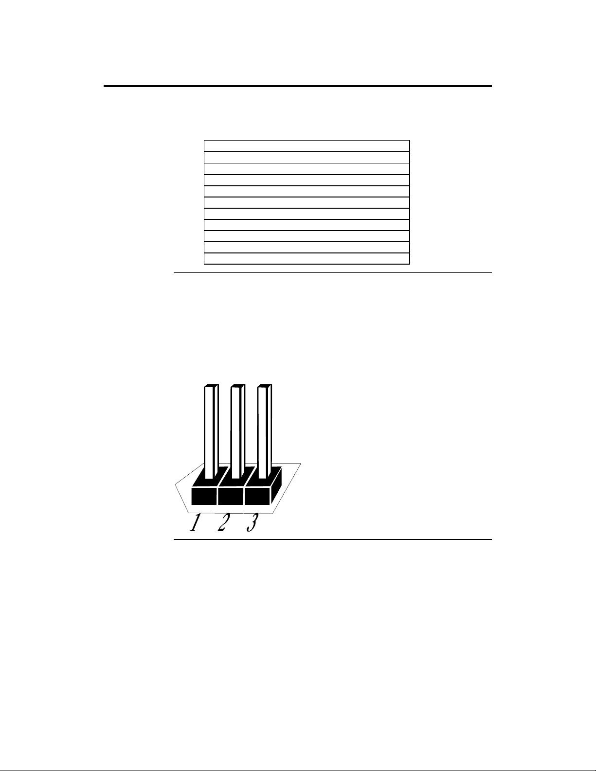
components are outlined by a white rectangular box with a broad arrow at one
end. Pin 1 is always at the arrow end of the white outlined box, as shown
below:
Chapter 1 Hardware Installation
Cont’d
29
Page 35
Step 6 Attach Connectors, Continued
Keyboard CableThe keyboard attaches via a standard six-pin DIN keyboard connector (J9).
Pin Assignments
1 Keyboard data
2 N/C
3 Ground
4 Vcc
5 Keyboard clock
6 N/C
IRQ 12 J24 is a 3-pin berg that specifies IRQ 12 use.
IRQ 12 Use J24
The onboard PS/2 mouse uses IRQ12. Short Pins 1-2 (factory
setting)
IRQ 12 is available for bus devices. Short Pins 2-3
PS/2 Mouse Cable Attach the customized 10-pin to 9-pin mouse connector cable supplied by
American Megatrends to the 10-pin mouse berg connector (J10) on the
baseboard. Attach the standard 9-pin mouse connector at the other end of the
mouse cable to the mouse connector port on the computer case. Incorrect mouse
installation can cause the system to hang.
Cont’d
Goliath PCI Pentium Pro EISA System User’s Guide
30
Page 36

Step 6 Attach Connectors, Continued
Connect Mouse Cable The mouse connector (J10) is a 10-pin berg. The mouse cable is the same
as the serial cable in the Goliath baseboard. Two serial cables are shipped with
the baseboard. Use one of these cables for the mouse.
Pin Description Pin Description
1 Mouse Clock 2 N/C
3 N/C 4 N/C
5 N/C 6 VCC
7 N/C 8 Mouse Data
9 Ground 10 N/C
Connectors When connecting chassis connectors to the baseboard, make sure to connect the
correct connector end. Most connector wires are color-coded. Match the color
of the wires leaving the switch or LED to the same pin on the connector end.
There may be more than one connector with the same color-coded wires. If so,
follow the wire to the switch or LED. Pin 1 is always indicated on the
baseboard.
J27 Reset J27 is a two-pin single-inline berg that is attached via a cable to an externally-
mounted reset switch. When the reset switch is pressed, the system performs a
hard reset. Pin 2 is ground and Pin 1 is Hard Reset.
Cont’d
Chapter 1 Hardware Installation
31
Page 37
Step 6 Attach Connectors, Continued
Speaker Connector J28 is a four-pin single-inline berg optionally attached via a cable to a
standard system speaker. AMIBIOS signals hardware problems through the
speaker. Pin 1 on the baseboard is identified by the arrow on the white box
around the berg.
Pin Description
1 Data Out
2 Ground
3 N/C
4 Ground
Keyboard Lock J22 is a five-pin single-inline berg that is attached via a cable to the keyboard
lock connector. The computer chassis may not include the keyboard lock and
Power LED on a single connector. The keyboard lock allows the user to lock
the keyboard. Pin 1 on the baseboard is identified.
Pin Description
1 LED power
2 LED power
3 Ground
4 Keyboard Lock
5 Ground
IDE Indicator LED J29 is a two-pin berg that is attached via a cable to the externally-mounted
IDE Activity LED. This LED lights when the IDE drive is running. Pin 1 is
Anode. Pin 2 is Ground.
Warning
In some IDE drives, you may have to disable the
IDE LED mounted on the drive by changing a
jumper or setting a switch on the IDE drive itself,
before the IDE drive sends a signal to this berg.
Goliath PCI Pentium Pro EISA System User’s Guide
32
Page 38

Step 7 Attach Serial Ports
Onboard Adapters The Goliath baseboard has:
• two serial ports (J5 and J6),
• a parallel port (J7),
• an IDE controller on the PCI bus. The IDE connector is J2.
• a floppy connector (J3).
The serial and parallel port connectors are described below.
Conflicts AMIBIOS minimizes conflicts between onboard and offboard I/O devices.
AMIBIOS automatically checks the adapter cards installed in the expansion
slots on the Goliath baseboard for a hard disk or floppy controller and serial or
parallel ports.
J6, J5 Serial J6 and J5 are 10-pin connectors that provide an AT-compatible serial port
interface. Connect the cables supplied with the Goliath system to the
customized American Megatrends 10-pin to 9-pin D type cable to the 10-pin
serial connectors. The serial port base I/O port address and other serial port
settings can be selected in Peripheral Setup in WINBIOS Setup. The serial
connector pinout is shown below.
Pin Description Pin Signal Description
1 Carrier Detect 6 Data Set Ready
2 Receive Data 7 Request to Send
3 Transmit Data 8 Clear to Send
4 Data Terminal
Ready
5 Ground 10 CUT PIN
9 Ring Indicator
Chapter 1 Hardware Installation
33
Page 39

Step 8 Attach Parallel Port
J7 Parallel Port J7 is a 26-pin connector for a parallel port. The J7 pinout is shown below.
Connect the American Megatrends customized 26-pin to DB25 cable provided
with the Goliath system to J7. All parallel port settings can be configured
through Peripheral Setup in WINBIOS Setup.
Pin Signal Description Pin Signal Description
1 STROBE# 2 PD0
3 PD1 4 PD2
5 PD3 6 PD4
7 PD5 8 PD6
9 PD7 10 ACK#
11 BUSY 12 PE
13 SLCT 14 AUTOFD#
15 ERROR# 16 INIT#
17 SLCTIN# 18 Ground
19 Ground 20 Ground
21 Ground 22 Ground
23 Ground 24 Ground
25 Ground 26 Ground
EPP DRQ J18 and J19 are 6-pin bergs that select the Enhanced Parallel Port (EPP) DRQ,
as follows:
EPP DRQ J18 J19
DRQ0 Short Pins 1-2 Short Pins 1-2
DRQ1 Short Pins 3-4 Short Pins 3-4
DRQ3 Short Pins 5-6 Short Pins 5-6
Factory Setting OPEN OPEN
Parallel IRQ J23 is a 3-pin berg that selects the IRQ used by the parallel port.
Parallel Port IRQ J23
IRQ 7 Short Pins 1-2 (factory setting)
IRQ 5 Short Pins 2-3
Cont’d
Goliath PCI Pentium Pro EISA System User’s Guide
34
Page 40

Step 9 Attach Floppy
J3 Floppy J3 is a 34-pin dual-inline berg. Connect the cable from the floppy drive to J3, as
shown below. The onboard floppy controller cannot be used if a hard disk card
with a floppy controller is installed. Choose Standard Setup and Peripheral
Setup to configure the floppy controller.
The baseboard supports up to two 720 KB, 1.44 MB, or 2.88 MB 3½" drives
and 360 KB and 1.2 MB 5¼" drives. The connecting cable is a 34-pin ribbon
connector with two 34-pin edge connectors for attaching the floppy disk drives.
There is a small twist in the cable between the floppy connectors. The last (end)
connector should be connected to floppy drive A::
Cont’d
Chapter 1 Hardware Installation
35
Page 41
Step 9 Attach Floppy, Continued
J3 Floppy Connector Pinout
Pin Use Pin Use
1 GND 2 DENSE1
3 GND 4 N/C
5 GND 6 DRATE0
7 GND 8 -INDEX
9 GND 10 -MOTOR0
11 GND 12 -FDSEL1
13 GND 14 -FDSEL0
15 GND 16 -MOTOR1
17 GND 18 DIR
19 GND 20 21 GND 22 -WDATA
23 GND 24 -WGATE
25 GND 26 -TRK0
27 GND 28 -WRPROT
29 GND 30 -RDATA
31 GND 32 HDSEL
33 GND 34 DSKCHNG
Twist in Floppy Cable
Floppy B to A Floppy B to A Floppy B to A Floppy B to A
10 to 16 12 to 14 14 to 12 16 to 10
11 to 15 13 to 13 15 to 11
Goliath PCI Pentium Pro EISA System User’s Guide
36
Page 42

Step 10 Attach IDE
IDE Drives Set the Onboard IDE option to Primary in Peripheral Setup to enable onboard
IDE.
Important
J20 must be OPEN.
Attach IDE Cable J2 is the IDE (Integrated Drive Electronics) hard disk drive connector. The
primary master and the primary slave IDE drives are connected by cable to J2,
as shown below.
J2 is a 40-pin dual-inline berg that connects an ATA IDE drive to the primary
onboard IDE connector. This baseboard supports IDE Modes 0, 1, 2, 3, and 4,
IDE prefetch, LBA (Logical Block Address) mode, high capacity drives (over
528 MB), 32-bit data transfer, and fast IDE transfer. These IDE features are
configured in Peripheral Setup in the WINBIOS Setup utility. Disable the
onboard IDE interface in Peripheral Setup to use an EISA ESDI, RLL, MFM,
or SCSI hard disk drive.
J21 IDE DREQ J21 is a 2-pin berg that enables the IDE DREQ. The settings are:
J21 Setting IDE DREQ
Shorted Enabled
OPEN None
Cont’d
Chapter 1 Hardware Installation
37
Page 43

Step 10 Attach IDE, Continued
J2 Pinout The J2 pinout is:
Pin Use Pin Use
1 -RESET 2 GND
3 DATA7 4 DATA8
5 DATA6 6 DATA9
7 DATA5 8 DATA10
9 DATA4 10 DATA11
11 DATA3 12 DATA12
13 DATA2 14 DATA13
15 DATA1 16 DATA14
17 DATA0 18 DATA15
19 GND 20 KEY (N/C)
21 N/C 22 GND
23 -IOW 24 GND
25 -IOR 26 GND
27 IDERDY 28 ALE
29 N/C 30 GND
31 INT14 32 -IOCS16
33 HA1 34 N/C
35 HA0 36 HA2
37 -CS0 38 -CS1
39 -IDEACT 40 GND
Goliath PCI Pentium Pro EISA System User’s Guide
38
Page 44

Step 11 Test and Configure
Review the following points before powering up:
• make sure that all adapter cards are seated properly,
• make sure all connectors are properly installed,
• make sure the CPU is seated properly,
• make sure there are no screws or other foreign material on the baseboard,
• plug the system into a surge-protected power strip, and
• make sure blank back panels are installed on the back of the chassis to
minimize RF emissions.
Start the Test Plug everything in and turn on the switch. If there are any signs of a problem,
turn off the unit immediately. Reinstall the connectors. Call Technical Support
if there are problems.
BIOS Errors If the system operates normally, a display should appear on the monitor. The
BIOS Power On Self Test (POST) should execute.
If POST does not run successfully, it will beep or display error messages. Beeps
indicate a serious problem with the system configuration or hardware. The
Beep Code indicates the problem. AMIBIOS Beep Codes are defined in the
AMIBIOS Technical Reference. Make sure the affected part is properly seated
and connected. An error message is displayed if the error is less serious.
Recheck the system configuration or the connections.
Configure the System Run WINBIOS Setup. Load the Optimal settings. Enter the requested
information and save the configuration data in NVRAM (Non-Volatile Random
Access Memory (also called CMOS RAM). The system will then reset, run
POST, and boot the operating system.
Chapter 1 Hardware Installation
39
Page 45

Page 46

2 WINBIOS Setup
In ISA and EISA computers, the system parameters (such as amount of
memory, type of disk drives and video displays, and many other elements) are
stored in NVRAM. Unlike the DRAM (dynamic random access memory) that is
used for standard system memory, NVRAM requires very little power. When
the computer is turned off, a back-up battery provides power to NVRAM, which
retains the system parameters. Every time the computer is powered-on, the
computer is configured with the values stored in NVRAM by the system BIOS,
which gains control when the computer is powered on.
The system parameters are configured by a system BIOS Setup utility.
Historically, BIOS Setup utilities have been character-based, required keyboard
input, and have had user interfaces that were not very intuitive.
Graphical Interface American Megatrends has a new type of system BIOS Setup utility.
WINBIOS Setup has a graphical user interface you can access using a mouse.
The WINBIOS Setup code is so compact that it can reside on the same ROM as
the system BIOS. The system configuration parameters are set by WINBIOS
Setup.
Since WINBIOS Setup resides in the ROM BIOS, it is available each time the
computer is turned on.
Starting WINBIOS Setup As POST executes, the following appears:
Hit <DEL> if you want to run SETUP
Press <Del> to run WINBIOS Setup.
Chapter 2 WINBIOS Setup 41
Page 47

Using a Mouse with WINBIOS Setup
WINBIOS Setup has a built-in mouse driver and can be accessed by either a
serial mouse or PS/2-style mouse. WINBIOS Setup supports MicrosoftCompatible serial mice and all PS/2-type mice.
The mouse click functions are: single click to change or select both global and
current fields and double click to perform an operation in the selected field.
Using the Keyboard with WINBIOS Setup
WINBIOS has a built-in keyboard driver that uses simple keystroke
combinations:
Keystroke Action
<Tab> Change or select a global field.
<→, ←, ↑, ↓
<Enter> Perform an operation in the current field.
+ Increment a value.
– Decrement a value.
<Esc> Abort any window function.
<PgUp> Return to the previous screen.
<PgDn> Advance to the next screen.
<Home> Returns to the beginning of the text.
<End> Advance to the end of the text.
<Ctrl><Alt><+> Change to high speed.
<Ctrl><Alt><-> Change to low speed.
Change or select the current field.
Goliath PCI Pentium Pro EISA System User’s Guide
42
Page 48

Section 1 Setup Options
WINBIOS Setup Menu
The WINBIOS Setup main menu is organized into four sections. Each of these
sections corresponds to a section in this chapter.
Each section contains several icons. Clicking on each icon activates a specific
AMIBIOS function. The WINBIOS Setup main windows and related functions
are described below.
Main Windows The WINBIOS Setup main windows are:
• Setup, described in Section 1, has icons that permit you to set system
configuration options such as date, time, hard disk type, floppy type, and
many others,
• Utilities, described in Section 2, sets the screen color and allows language
changes,
• Security, described in Section, has three icons that control AMIBIOS
security features, and
• Default, described in Section 4, this section has three icons that permit you
to select a group of settings for all WINBIOS Setup options.
Chapter 2 WINBIOS Setup 43
Page 49

Section 1 Setup
Standard Setup
Standard Setup options are displayed by choosing the Standard icon from the
WINBIOS Setup main menu. All Standard Setup options are described in this
section.
Date/Time Select the Standard option. Select the Date and Time icon. The current values
for each category are displayed. Enter new values through the keyboard.
Floppy Drive A: and B: Move the cursor to these fields via ↑ and ↓ and select the floppy type.
The settings are 360 KB 5¼ inch, 1.2 MB 5¼ inch, 720 KB 3½ inch, 1.44 MB
3½ inch, or 2.88 MB 3½ inch.
Goliath PCI Pentium Pro EISA System User’s Guide
44
Page 50

Standard Setup, Continued
Pri Master, Pri Slave, Sec Master, Sec Slave Select one of these hard disk drive icons to
configure the hard disk drive named in the option. Select Auto from the drive
parameters screen to let AMIBIOS automatically configure the drive. A screen
with a list of drive parameters appears. Click on OK to configure the drive.
Drive Type How to Configure
SCSI
IDE
CD-ROM
Standard
MFM Drive
Non-
Standard
MFM Drive
Select Type. Select Not Installed in the drive parameter
screen. The SCSI drivers provided by the SCSI drive or
SCSI host adapter manufacturer should allow you to
configure the SCSI drive.
Select Type. Select Auto to let AMIBIOS determine the
parameters. Click on OK when AMIBIOS displays the drive
parameters.
Select LBA/Large Mode. Select On if the drive has a
capacity greater than 540 MB.
Select Block Mode. Select On to allow block mode data
transfers.
Select 32-Bit Transfer. Select On to allow 32-bit data
transfers.
Select the PIO Mode. It is best to select Auto to allow
AMIBIOS to determine the PIO mode. If you select a PIO
mode that is not supported by the IDE drive, the drive will
not work properly. If you are absolutely certain that you
know the drive’s PIO mode, select PIO mode 0 - 5, as
appropriate.
Select Type. Select CDROM. Click on OK when AMIBIOS
displays the drive parameters.
Select Type. You must know the drive parameters. Select
the drive type that exactly matches your drive’s parameters.
Select Type. If the drive parameters do not match the drive
parameters listed for drive types 1 - 46, select User and
enter the correct hard disk drive parameters.
Chapter 2 WINBIOS Setup 45
Cont’d
Page 51

Standard Setup, Continued
Entering Drive Parameters You can also enter the hard disk drive parameters. The drive
parameters are:
Parameter Description
Type The number for a drive with certain identification
parameters.
Cylinders The number of cylinders in the disk drive.
Heads The number of heads.
Write
Precompensation
Landing Zone This number is the cylinder location where the heads
Sectors The number of sectors per track. MFM drives have 17
Capacity The formatted capacity of the drive is the number of
The actual physical size of a sector gets progressively
smaller as the track diameter diminishes. Yet each
sector must still hold 512 bytes. Write
precompensation circuitry on the hard disk
compensates for the physical difference in sector size
by boosting the write current for sectors on inner
tracks. This parameter is the track number on the disk
surface where write precompensation begins.
normally park when the system is shut down.
sectors per track. RLL drives have 26 sectors per
track. ESDI drives have 34 sectors per track. SCSI
and IDE drives have even more sectors per track.
heads times the number of cylinders times the number
of sectors per track times 512 (bytes per sector).
Cont’d
Goliath PCI Pentium Pro EISA System User’s Guide
46
Page 52

Standard Setup, Continued
Hard Disk Drive Types
Type Cylinders Heads Write
1 306 4 128 305 17 10 MB
2 615 4 300 615 17 20 MB
3 615 6 300 615 17 31 MB
4 940 8 512 940 17 62 MB
5 940 6 512 940 17 47 MB
6 615 4 65535 615 17 20 MB
7 462 8 256 511 17 31 MB
8 733 5 65535 733 17 30 MB
9 900 15 65535 901 17 112 MB
10 820 3 65535 820 17 20 MB
11 855 5 65535 855 17 35 MB
12 855 7 65535 855 17 50 MB
13 306 8 128 319 17 20 MB
14 733 7 65535 733 17 43 MB
16 612 4 0 663 17 20 MB
17 977 5 300 977 17 41 MB
18 977 7 65535 977 17 57 MB
19 1024 7 512 1023 17 60 MB
20 733 5 300 732 17 30 MB
21 733 7 300 732 17 43 MB
22 733 5 300 733 17 30 MB
23 306 4 0 336 17 10 MB
24 925 7 0 925 17 54 MB
25 925 9 65535 925 17 69 MB
26 754 7 754 754 17 44 MB
27 754 11 65535 754 17 69 MB
28 699 7 256 699 17 41 MB
29 823 10 65535 823 17 68 MB
30 918 7 918 918 17 53 MB
31 1024 11 65535 1024 17 94 MB
32 1024 15 65535 1024 17 128 MB
33 1024 5 1024 1024 17 43 MB
34 612 2 128 612 17 10 MB
35 1024 9 65535 1024 17 77 MB
36 1024 8 512 1024 17 68 MB
37 615 8 128 615 17 41 MB
38 987 3 987 987 17 25 MB
39 987 7 987 987 17 57 MB
40 820 6 820 820 17 41 MB
41 977 5 977 977 17 41 MB
42 981 5 981 981 17 41 MB
43 830 7 512 830 17 48 MB
44 830 10 65535 830 17 69 MB
45 917 15 65535 918 17 114 MB
46 1224 15 65535 1223 17 152 MB
AMIBIOS automatically sets IDE drive parameters. Select USER to enter MFM, ESDI, or RLL drive
parameters. Select Not Installed for SCSI drives. Select CDROM for CD-ROM drives.
Precompensation
Landing
Zone
Sectors Capacity
Chapter 2 WINBIOS Setup 47
Page 53

Advanced Setup
The WINBIOS Setup options described in this section are displayed by
choosing the Advanced Setup icon from the Setup section on the WINBIOS
Setup main menu. All Advanced Setup options are described in this section.
Primary Display This option configures the primary display subsystem in the computer. The
settings are Mono (monochrome), 40CGA, 80CGA, or VGA/EGA. The Optimal
and Fail-Safe default settings are VGA/EGA.
Mouse Support When this option is set to Enabled, AMIBIOS supports a PS/2-type mouse. The
settings are Enabled or Disabled. The Optimal and Fail-Safe default settings
are Enabled.
Boot Up Num Lock When this option is set to On, AMIBIOS turns off the Num Lock key when
the system is powered on so you can use the arrow keys on both the numeric
keypad and the keyboard. The settings are On or Off. The Optimal default and
Fail-Safe default settings are On.
Password CheckThis option specifies the type of AMIBIOS password protection that is
implemented. The Optimal and Fail-Safe default settings are Setup. The
settings are:
Setting Description
Setup
Always
The password prompt appears only when an you
attempts to run WINBIOS Setup.
A password prompt appears every time the computer
is powered on or rebooted.
The AMIBIOS password does not have to be enabled. You set the password by
choosing the Password icon on the WINBIOS Setup screen.
Cont’d
Goliath PCI Pentium Pro EISA System User’s Guide
48
Page 54

Advanced Setup, Continued
OS/2 Compatible Mode Set this option to Enabled to permit AMIBIOS to run properly if OS/2
or any other operating system that does not support Plug and Play is to be run
on this computer. The settings are Enabled or Disabled. The Optimal and FailSafe default settings are Disabled.
Floppy Drive Swap Set this option to Enabled to specify that floppy drives A: and B: are
swapped. The settings are Enabled or Disabled. The Optimal and Fail-Safe
default settings are Disabled.
Quick Boot Set this option to Enabled to permit AMIBIOS to boot the operating system
within 5 seconds after the computer is powered on. This option replaces the old
Above 1 MB Memory Test option. The Optimal default setting is Disabled.
The Fail-Safe default setting is Disabled.
Setting Description
Disabled AMIBIOS tests all system memory. AMIBIOS wait up to 40 seconds for a
READY signal from the IDE drive. AMIBIOS waits up to.5 seconds after
sending a RESET signal to the IDE drive to permit the IDE drive to send a
READY signal. AMIBIOS checks if the <Del> key was pressed. WINBIOS
Setup is executed if <Del> was pressed.
Enabled AMIBIOS does not test any system memory above 1 MB. AMIBIOS does not
wait for a READY signal from the IDE drive. If a READY signal is not
received immediately, AMIBIOS does not configure the drive. AMIBIOS
does not wait.5 seconds after sending a RESET signal to the IDE drive.
AMIBIOS does not check if the <Del> key was pressed. You cannot run
WINBIOS Setup at system boot if this setting is selected.
Cont’d
Chapter 2 WINBIOS Setup 49
Page 55

Advanced Setup, Continued
Boot Up Sequence This option sets the sequence of boot drives (floppy drive A:, hard disk drive
C:, or a CD-ROM drive) that AMIBIOS attempts to boot from after AMIBIOS
POST completes. The settings are C:,A:, CDROM, A:,C:, CDROM, or
CDROM, C:,A:. The Optimal and Fail-Safe default settings are C:,A:,CDROM.
CPU Microcode Update Set this option to Enabled to permit the Intel Pentium Pro CPU
microcode to be updated. The CPU may malfunction if this option is set to
Disabled. The settings are Enabled or Disabled. The Optimal and Fail-Safe
default settings are Enabled.
MPS Mode This option specifies the version of the Intel Multiprocessor Specification
(MPS) being used. The settings are 1.1 or 1.4. The Optimal and Fail-Safe
default settings are 1.4. Windows NT supports MPS 1.4. OS/2 supports MPS
1.1.
L1/L2 Cache This option specifies the caching algorithm used for both L1 (internal) and L2
(secondary) cache memory on the CPU. The settings are WriteThru, WriteBack,
or Disabled. The Optimal and Fail-Safe default settings are WriteBack.
System BIOS Cacheable AMIBIOS always copies the system BIOS from ROM to RAM for
faster execution. Set this option to Enabled to permit the contents of the
F0000h RAM memory segment to be written to and read from cache memory.
The settings are Enabled or Disabled. The Optimal default setting is Enabled.
The Fail-Safe default setting is Disabled.
Cont’d
Goliath PCI Pentium Pro EISA System User’s Guide
50
Page 56

Advanced Setup, Continued
VGA Memory Cache Mode This option specifies if the type of system memory installed in the
computer supports shared use of system memory between video memory and
system memory. The settings are UC (Uncacheable) memory or USWC
(Uncacheable, Speculatable, Write-Combining) memory. The Optimal and
Fail-Safe default settings are UC.
C000,32K Shadow These options specify how the contents of the video ROM are handled. The
settings are:
Setting Description
Disabled
Cached
Shadow
The Optimal default setting is Cached. The Fail-Safe default setting is
Disabled.
C800,16K Shadow
CC00,16K Shadow
D000,16K Shadow
D400,16K Shadow
D800,16K Shadow
DC00,16K Shadow These options specify how the contents of the adapter ROM named in the
option title are handled. The ROM area not used by ISA adapter cards is
allocated to PCI adapter cards. The settings:
The contents of the video ROM are not copied to RAM.
The contents of the video ROM area from C0000h - C7FFFh
are copied from ROM to the corresponding RAM address for
faster execution. After being copied to RAM, the video ROM
contents can also be read from and written to cache memory.
The contents of the video ROM area from C0000h - C7FFFh
are copied from ROM to RAM for faster execution.
Setting Description
Disabled
Cached
Shadow
The contents of the video ROM are not copied to RAM.
The contents of the video ROM area from C0000h - C7FFFh
are copied from ROM to the corresponding RAM address for
faster execution. After being copied to RAM, the video ROM
contents can also be read from and written to cache memory.
The contents of the video ROM area from C0000h - C7FFFh
are copied from ROM to RAM for faster execution.
The Optimal and Fail-Safe default settings are Disabled.
Chapter 2 WINBIOS Setup 51
Page 57

Chipset Setup
Choose the Chipset Setup icon from the Setup section on the AMIBIOS Setup
main menu. All Chipset Setup options are then displayed and are described in
this chapter.
CPU Base Frequency This option sets the CPU external frequency. The settings are 50 MHz, 60
MHz, or 66 MHz. The Optimal default setting is 60 MHz. The Fail-Safe default
setting is 50 MHz.
Fast Strings Set this option to Enabled to enable fast strings. The settings are Disabled or
Enabled. The Optimal and Fail-Safe default settings are Disabled.
ECC Set this option to Enabled to enable ECC (Error Checking and Correction) in
the Orion Memory Controller (OMC). The OMC detects errors on the Pentium
Pro system bus by checking the ECC value with data and the parity provided
with the control signals. The OMC also generates ECC with data and parity
with control signals so that errors can be detected on the bus. The settings are
Enabled or Disabled. The Optimal default setting is Enabled. The Fail-Safe
default setting is Disabled.
Cont’d
Goliath PCI Pentium Pro EISA System User’s Guide
52
Page 58

Chipset Setup, Continued
In-Order Queue Depth This option specifies the queue depth on the Pentium Pro system bus.
Queue entries are executed in the order that they were placed on the queue. The
settings are 1 or 8. The Fail-Safe default setting is 8. The Optimal default
setting is 8.
OPB P6 To PCI Write Posting Set this option to Enabled to enable Pentium Pro writes to the
PCI bus to be posted in the OPB (Orion PCI Bridge). The write is actually
performed at a later time, but setting this option to Enabled guarantees that the
write will be performed. The settings are Enabled or Disabled. The Optimal
default setting is Enabled. The Fail-Safe default setting is Disabled.
OPB PCI To P6 Write Posting Set this option to Enabled to enable PCI writes to the Pentium
Pro system bus to be posted in the OPB (Orion PCI Bridge). The write is
actually performed at a later time, but setting this option to Enabled guarantees
that the write will be performed. The settings are Enabled or Disabled. The
Optimal default setting is Enabled. The Fail-Safe default setting is Disabled.
OPB Burst Write Assembly Set this option to Enabled to enable back-to-back sequential
Pentium Pro to PCI memory space cache line writes to USWC memory to be
converted to continuous PCI write bursts. The settings are Enabled or Disabled.
The Optimal default setting is Enabled. The Fail-Safe default setting is
Disabled.
OPB P6 Line Read Set this option to Enabled to enable PCI Memory Read Line commands to
fetch full Pentium Pro cache lines. The settings are Enabled or Disabled. The
Optimal default setting is Enabled. The Fail-Safe default setting is Disabled.
Cont’d
Chapter 2 WINBIOS Setup 53
Page 59

Chipset Setup, Continued
OPB P6 Line Read Prefetch Set this option to Enabled to enable PCI Memory Read Line
commands to fetch a full Pentium Pro cache line plus a prefetch of up to 3
additional full Pentium Pro cache lines. The prefetch operation does not cross 4
KB boundaries. The settings are Enabled or Disabled. The Optimal default
setting is Enabled. The Fail-Safe default setting is Disabled.
PCEB GAT Mode Set this option to Enabled to enable GAT mode. The settings are Enabled or
Disabled. The Optimal default setting is Enabled. The Fail-Safe default setting
is Disabled.
PCEB EISA-PCI Line Buffer Set this option to Enabled to enable the EISA-PCI line buffer.
The settings are Enabled or Disabled. The Optimal default setting is Enabled.
The Fail-Safe default setting is Disabled.
PCEB Master Retry Timer This option sets the length of a delay inserted before an EISA bus
mastering device retries a failed operation. The settings are Disabled, 16 CLKs,
32 CLKs or 64 CLKs. The Optimal default setting is Disabled. The Fail-Safe
default setting is Disabled.
OMC Write CAS This option specifies the length of a delay inserted before the Write Column
Address Strobe (CAS) signal is sent by the Orion Memory Controller (OMC).
The settings are 2 CLKs or 3 CLKs. The Optimal default setting is 2 CLKs. The
Fail-Safe default setting is 3 CLKs.
Watchdog Timer Set this option to Enabled to enable the watchdog timer. The settings are
Enabled or Disabled. The Optimal and Fail-Safe default settings are Disabled.
Goliath PCI Pentium Pro EISA System User’s Guide
54
Page 60

PCI/PnP Setup
Choose the PCI/PnP Setup icon from the WINBIOS Setup screen to display the
PCI and Plug and Play Setup options, described below.
PCI VGA Palette Snoop When this option is set to Enabled, multiple VGA devices operating on
different buses can handle data from the CPU on each set of palette registers on
every video device. Bit 5 of the command register in the PCI device
configuration space is the VGA Palette Snoop bit (0 is disabled). For example,
if there are two VGA devices in the computer (one PCI and one ISA) and the:
VGA Palette
Snoop Bit Setting
Disabled
Enabled
Data read and written by the CPU is only directed
to the PCI VGA device's palette registers.
Data read and written by the CPU is directed to the
both the PCI VGA device's palette registers and the
ISA VGA device palette registers, permitting the
palette registers of both devices to be identical.
Action
This option must be set to Enabled if an ISA adapter card requires VGA palette
snooping. The settings are Enabled or Disabled. The Optimal and Fail-Safe
default settings are Disabled.
PCI VGA Frame Buffering Set this option to Enabled to enable VGA frame buffering. The
settings are Enabled or Disabled. The Optimal and Fail-Safe default settings
are Disabled.
Cont’d
Chapter 2 WINBIOS Setup 55
Page 61

PCI/PnP Setup, Continued
PCI Slot-1 Latency Timer
PCI Slot-2 Latency Timer
PCI Slot-3 Latency Timer
PCI Slot-4 Latency Timer These options specify the latency timings (in PCI clocks) for PCI
devices installed in the four PCI expansion slots. If no PCI card is installed in a
PCI slot, the corresponding WINBIOS Setup option cannot be selected. The
settings are 32, 64, 96, 128, 160, 192, 224, or 248. The Optimal default setting
is 64. The Fail-Safe default setting is 128.
PCI Slot 1 IRQ Preference
PCI Slot 2 IRQ Preference
PCI Slot 3 IRQ Preference
PCI Slot 4 IRQ Preference
PCI Slot 5 IRQ Preference
PCI Slot 6 IRQ Preference These options specify the IRQ priority to be used for PCI devices
installed in PCI expansion slots. The settings are Auto, IRQ3, IRQ4, IRQ5,
IRQ7, IRQ9, IRQ10, IRQ11, IRQ14, or IRQ15. The Optimal and Fail-Safe
default settings are Auto.
Cont’d
Goliath PCI Pentium Pro EISA System User’s Guide
56
Page 62

PCI/PnP Setup, Continued
IRQ3
IRQ4
IRQ5
IRQ7
IRQ9
IRQ10
IRQ11
IRQ12
IRQ14
IRQ15 These options specify the bus or the PCI slot range that the specified IRQ line is
used on. They allow you to reserve IRQs for legacy ISA adapter cards. You can
also specify the IRQ used for each group of PCI expansion slots. The Goliath
base board has two groups of PCI expansion slots: The primary group (PCI
expansion slots 1, 2, and 3) and the secondary PCI expansion slots (PCI
expansion slots 4, 5, and 6). All IRQs are available to the primary PCI slots.
The IRQ pool for the secondary PCI slots is: IRQ3, IRQ5, IRQ7, IRQ10, and
IRQ15. Make sure that at least one of these IRQs is reserved for the secondary
PCI slots if you have installed a PCI adapter card in PCI expansion slot 4, 5, or
6.
These options determine if AMIBIOS should remove an IRQ from the pool of
available IRQs passed to devices that can be configured by the BIOS. The
available IRQ pool is determined by reading the ESCD NVRAM. If more IRQs
must be removed from the pool, set these options to reserve the IRQ by
assigning an ISA setting to it. Onboard I/O is configured by AMIBIOS. All
IRQs used by onboard I/O are configured as PnP. IRQ12 only appears if the
Mouse Support option in Advanced Setup is set to Disabled. IRQ14 will not be
available if the Onboard Primary IDE Controller option is set to Enabled. If all
IRQs are set to ISA and IRQ14 is allocated to the onboard PCI IDE, IRQ9 will
still be available for PnP devices, since at least one IRQ must be available for
PnP. The settings are ISA, Prim-Slots, or Sec-Slots.
Cont’d
Chapter 2 WINBIOS Setup 57
Page 63

PCI/PnP Setup, Continued
IRQ Options, cont’d The Optimal and Fail-Safe default settings are:
PCI/PnP IRQ Option Optimal Fail-Safe
IRQ3
IRQ4
IRQ5
IRQ7
IRQ9
IRQ10
IRQ11
IRQ12
IRQ14
IRQ15
DMA Channel 0
DMA Channel 1
DMA Channel 3
DMA Channel 5
DMA Channel 6
DMA Channel 7 These options specify the bus that the DMA channel is used on. The settings
are PnP or ISA/EISA. The Optimal and Fail-Safe default settings are PnP.
PnP Prim-Slots
PnP Prim-Slots
Sec-Slots Sec-Slots
PnP Prim-Slots
Prim-Slots Prim-Slots
Sec-Slots Sec-Slots
Prim-Slots Prim-Slots
PnP PnP
Prim-Slots Prim-Slots
Sec-Slots Sec-Slots
Reserved Memory Size This option specifies the size of the memory area reserved for legacy
ISA adapter cards. The settings are Disabled, 16K, 32K, or 64K. The Optimal
and Fail-Safe default settings are Disabled.
Reserved Memory Address This option specifies the beginning address (in hex) of the reserved
memory area. The specified ROM memory area is reserved for use by legacy
ISA adapter cards. This option does not appear if the Reserved Memory Size
option is set to Disabled. The settings are C0000, C4000, C8000, CC000,
D0000, D4000, D8000, or DC000. The Optimal and Fail-Safe default settings
are N/A.
Goliath PCI Pentium Pro EISA System User’s Guide
58
Page 64

Peripheral Setup
Choose the Peripheral Setup icon from the WINBIOS Setup screen to display
the Peripheral Setup options, described below.
Onboard Floppy Controller This option enables the floppy drive controller on the motherboard.
The settings are Enabled or Disabled. The Optimal and Fail-Safe default
settings are Enabled.
Onboard Primary IDE Controller Set this option to Enabled to enable the onboard IDE
controller. The settings are Disabled or Enabled. The Optimal and Fail-Safe
default settings are Disabled.
Onboard IDE Bus Master Set this option to Enabled to enable PCI bus mastering support for
the onboard IDE controller. This option only appears if the Onboard Primary
IDE Controller option is set to Enabled. The settings are Enabled or Disabled.
The Optimal default setting is Disabled. The Fail-Safe default setting is N/A.
Serial Port1 Address This option specifies the base I/O port address used by serial port 1. The
settings are Disabled, 3F8h, or 3E8h. The Optimal default setting is 3F8h. The
Fail-Safe default setting is Disabled. The Fail-Safe default setting cannot be
changed.
Serial Port1 FIFO Set this option to Enabled to enable the FIFO buffer for serial port1. The
settings are Enabled or Disabled. The Optimal default setting is Disabled. The
Fail-Safe default setting is N/A.
Serial Port2 Address This option specifies the base I/O port address of serial port 2. The settings
are Disabled, 2F8h, or 2E8h. The Optimal default setting is 2F8h. The FailSafe default setting is Disabled. The Fail-Safe default setting cannot be
changed.
Cont’d
Chapter 2 WINBIOS Setup 59
Page 65

Peripheral Setup, Continued
Serial Port2 FIFO Set this option to Enabled to enable the FIFO buffer for serial port2. The
settings are Enabled or Disabled. The Optimal default setting is Disabled. The
Fail-Safe default setting is N/A.
Parallel Port Address This option specifies the base I/O port address of the parallel port on the
motherboard. The settings are Disabled, 378h, or 278h. The Optimal default
setting is 378h. The Fail-Safe default setting is Disabled. The Fail-Safe default
setting cannot be changed.
Parallel Port Mode This option specifies the parallel port mode. The Optimal default setting is
Normal. The Fail-Safe default setting is N/A. The settings are:
Setting Description
Normal
EPP
ECP
The normal parallel port mode is used.
The parallel port can be used with devices that adhere to the Enhanced
Parallel Port (EPP) specification. EPP uses the existing parallel port
signals to provide asymmetric bidirectional data transfer driven by the
host device.
The parallel port can be used with devices that adhere to the Extended
Capabilities Port (ECP) specification. ECP uses the DMA protocol to
achieve data transfer rates up to 2.5 Megabits per second. ECP provides
symmetric bidirectional communication.
Parallel Port DMA Channel This option is only available if the setting for the Parallel Port
Mode option is ECP. This option sets the DMA channel used by the parallel
port. The settings are Disabled, DMA Ch 0, DMA Ch 1, or DMA Ch 3. The
Optimal and Fail-Safe default settings are N/A.
Goliath PCI Pentium Pro EISA System User’s Guide
60
Page 66

Section 2 Security
AMIBIOS Password Support
WINBIOS Setup has a two-level password feature. A Supervisor password and
a User password can be configured. Both the Supervisor and User password or
either password can be configured.
Supervisor Password The Supervisor password takes precedence over the User password.
WINBIOS setup can be configured so that certain Setup screens or options only
appear when the Supervisor password has been properly entered.
User Password The computer can be configured so that all users must enter a password every
time the system boots or when WINBIOS Setup is executed.
Chapter 2 WINBIOS Setup 61
Page 67
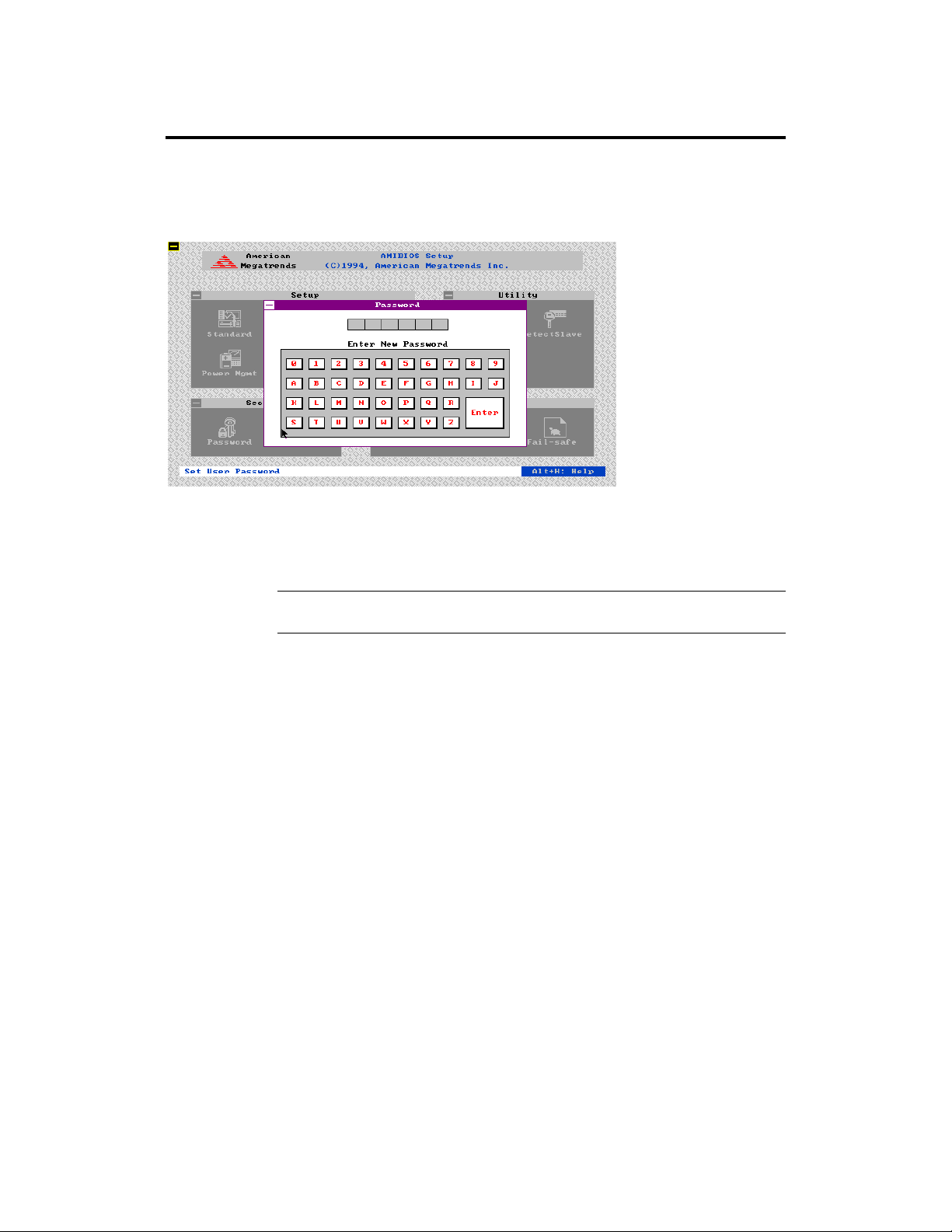
Setting a Password
The password check option is enabled in Advanced Setup by choosing either
Always (the password prompt appears every time the system is powered on) or
Setup (the password prompt appears only when WINBIOS is run). The
password is encrypted and stored in NVRAM.
As shown on the above screen, you are prompted for a 1 – 6 character
password. You can either type the password on the keyboard or select each
letter of the password, one at a time, using the mouse. The password does not
appear on the screen when typed. Make sure you write it down. If you forget it,
you must drain NVRAM and reconfigure.
If You Do Not Want to Use a Password Just press <Enter> when the password prompt appears.
Goliath PCI Pentium Pro EISA System User’s Guide
62
Page 68

Changing a Password
Select the Password icon from the Security section of the WINBIOS Setup
main menu. Enter the password and press <Enter>. The screen does not display
the characters entered. After the new password is entered, retype the new
password as prompted and press <Enter>. If the password confirmation is
incorrect, an error message appears. If the new password is entered without
error, press <Esc> to return to the WINBIOS Main Menu. The password is
stored in NVRAM after WINBIOS completes. The next time the system boots,
you are prompted for the password if the password function is present and is
enabled.
Remember the PasswordKeep a record of the new password when the password is changed. If
you forget the password, remove the computer cover, set switch 1-2 (the DIAG
switch) to ON, power on the computer. AMIBIOS will erase the password.
Anti-Virus
When this icon is selected from the Security section of the WINBIOS Setup
main menu, AMIBIOS issues a warning when any program (or virus) issues a
Disk Format command or attempts to write to the boot sector of the hard disk
drive. The settings are Enabled or Disabled. If enabled, the following appears
when a write is attempted to the boot sector. You may have to type N several
times to prevent the boot sector write.
Boot Sector Write!!!
Possible VIRUS: Continue (Y/N)? _
The following appears after any attempt to format any cylinder, head, or sector
of any hard disk drive via the BIOS INT 13h Hard Disk Drive Service:
Format!!!
Possible VIRUS: Continue (Y/N)? _
Chapter 2 WINBIOS Setup 63
Page 69

Section 3 Utility
The icons in this section of the WINBIOS Setup main screen permit you to
choose a different set of colors for the WINBIOS Setup screens and to use a set
of screen instructions written in a different language. The text for the screen
messages written different language must have been incorporated into the
AMIBIOS when the BIOS was manufactured.
Color Set Color Set sets the Setup screen colors.
Language If this feature is enabled, you can select WINBIOS Setup messages in different
languages.
Goliath PCI Pentium Pro EISA System User’s Guide
64
Page 70

Section 4 Default
The icons in this section permit you to select a group of settings for all
WINBIOS Setup options. Not only can you use these icons to quickly set system
configuration parameters, you can choose a group of settings that have a better
chance of working when the system is having configuration-related problems.
Original Choose the Original icon to return to the system configuration values present in
WINBIOS Setup when you first began this WINBIOS Setup session.
Optimal You can load the optimal default settings for the WINBIOS by
selecting the Optimal icon. The Optimal default settings are best-case values
that should optimize system performance. If NVRAM is corrupted, the Optimal
settings are loaded automatically.
Fail-Safe You can load the Fail-Safe WINBIOS Setup option settings by selecting the
Fail-Safe icon from the Default section of the WINBIOS Setup main menu.
The Fail-Safe settings provide far from optimal system performance, but are the
most stable settings. Use this option as a diagnostic aid if the system is
behaving erratically.
Chapter 2 WINBIOS Setup 65
Page 71

Goliath PCI Pentium Pro EISA System User’s Guide
66
Page 72

3 Programming the Flash ROM
The Goliath system uses Flash EPROM to store the system BIOS. The
advantage of Flash EPROM is the EPROM chip does not have to be replaced to
update the BIOS. You can actually reprogram the BIOS, using a ROM file
supplied by American Megatrends.
J26 J26 is a 3-pin berg that enables flash EPROM programming. In normal
operation, Pins 2-3 of J26 are always shorted. This is the factory setting.
Programming the Flash EPROM
Step Action
1 Turn power off. Make sure the computer has a working speaker.
2 Remove the computer cover.
3 Insert the floppy disk with the S730P.ROM file in drive A:.
4 Before DOS boots, press and hold down the <Ctrl> and
<Home> keys to reprogram the Flash EPROM-based AMIBIOS.
The bootblock code immediately reads the A: drive, looking for
the new BIOS information.
5 When the flash ROM has successfully been programmed, the
computer will reboot.
6 Replace the computer cover and reboot.
Cont’d
Chapter 3 Programming the Flash ROM 67
Page 73

Programming the Flash ROM, Continued
Bootblock BIOS Actions When you reprogram from system boot, the bootblock BIOS code:
Reads S730P.ROM from the root directory of the floppy disk in drive A:.
Erases the Flash EPROM.
Programs the Flash EPROM with the data read from the floppy disk in drive
A:.
Generates a CPU reset, rebooting the computer.
The bootblock part of the Flash EPROM is not programmed. Should you
inadvertently open the disk drive door or turn power off to the computer while
programming the Flash EPROM, the bootblock will be unaffected. Simply turn
power back on and begin the Flash ROM programming process again.
S730P.ROM S730P.ROM resides on a floppy disk and contains the updated main BIOS
code. American Megatrends will provide this file when the AMIBIOS for the
Goliath EISA baseboard must be updated.
S730P.ROM must be present in the root directory of the floppy disk before the
onboard Flash EPROM can be reprogrammed. The file that has the main BIOS
code must be named S730P.ROM.
Cont’d
Goliath PCI Pentium Pro EISA System User’s Guide
68
Page 74

Programming the Flash ROM, Continued
Sequence of Operation The sequence of operation and expected behavior of the bootblock
BIOS code is:
Step Expected behavior
1 Look for floppy
disk.
2 Look for
S730P.ROM on the
floppy disk.
3 Read the floppy
disk.
4 Check for BIOS file
size.
5 Check for Flash
EPROM.
6 Erase the Flash
EPROM.
7 Program the Flash
EPROM.
8 Continue
programming the
Flash EPROM.
9 AMIFlash does a
reset.
The system beeps one time before the BIOS attempts to
read from floppy drive A:.
S730P.ROM must be in the root directory of the floppy
disk in drive A:. There is no beep if successful.
The floppy disk is read. There is no beep if this step is
successful.
The BIOS file size is checked. There is no beep if this
step is successful.
The BIOS looks for an Intel i28F001BX-T Flash
EPROM. It does not beep if this step is successful.
Two beeps sound when the BIOS begins erasing the
Flash EPROM.
Three beeps sound when the AMIFlash Code begins
reprogramming the Flash EPROM.
Four beeps sound when reprogramming has been
successfully completed.
A CPU reset is generated to reboot the computer.
Chapter 3 Programming the Flash ROM 69
Page 75

Programming the Flash ROM, Continued
Beep Codes The bootblock code produces a series of beeps during Flash ROM programming
to:
• signify completion of a step (as shown on the previous screen), or to
• signal an error.
Error beeps are arranged in a coded sequence and have different meanings
depending on when they occur. The error beep codes and when they can occur
are:
Number of
Beeps
1 Insert diskette in floppy drive A:.
2 The AMIBOOT.ROM file was not found in the root directory
of the diskette in floppy drive A:.
3 Base memory error.
4 Flash program successful.
5 Floppy read error.
6 Keyboard controller BAT command failed.
7 No Flash EPROM detected.
8 Floppy controller failure.
9 Bootblock BIOS checksum error.
10 Flash erase error.
11 Flash program error.
12 AMIBOOT.ROM file size error.
Continuous
beep
Flash Programming successful. Turn power off. The turn
power on again to restart.
Description
Goliath PCI Pentium Pro EISA System User’s Guide
70
Page 76

Bootblock Code Checkpoint Codes
Code Description
E0h Verify the bootblock BIOS checksum. Disable the internal
cache, DMA, and interrupt controllers. Initialize the
system timer. Start memory refresh.
E1h Initialize the chipset registers. Set the BIOS size to 128K.
Make the 512 KB base memory available.
E2h Test the base 64 KB of system memory. Send the BAT
command to the keyboard controller. Make sure that
<Ctrl> <Home> was pressed. Verify the main system
BIOS checksum.
E3h The main system BIOS is good. Transfer control to the
main system BIOS.
E4h Start the memory test.
E5h The memory test is over. Initialize the interrupt vector
table.
E6h Initialize the DMA and interrupt controllers.
E7h Determine the CPU internal clock frequency.
E8h Initialize the I/O chipset, if any.
E9h Program the CPU clock-dependent chip set parameters.
EAh Enable the timer and the floppy diskette interrupt. Enable
the internal cache. Copy the bootblock BIOS and pass
control to the bootblock BIOS in the 0000h segment.
EDh Initialize the floppy drive.
EEh Look for a diskette in drive A:. Read the first sector of the
diskette.
EFh Floppy read error.
F0h Search for AMIBOOT.ROM in the root directory of the
floppy diskette in drive A:.
F1h The AMIBOOT.ROM file is not in the root directory.
F2h Read the FAT. Analyze the FAT to find the clusters
occupied by the AMIBOOT.ROM.
F3h Start reading the AMIBOOT.ROM file, cluster by cluster.
F4h The AMIBOOT.ROM file is not the correct size.
F5h Disable the internal cache. Raise the Vpp. Enable Flash
write and reset the Flash ROM.
FBh Detect the flash type.
FCh Start erasing flash blocks.
FDh Program the Flash ROM in the E0000-EFFFFh region.
FEh Start programming Flash at F0000-FFFFF region.
FFh Flash programming is successful. The computer reboots.
Chapter 3 Programming the Flash ROM 71
Page 77

Goliath PCI Pentium Pro EISA System User’s Guide
72
Page 78
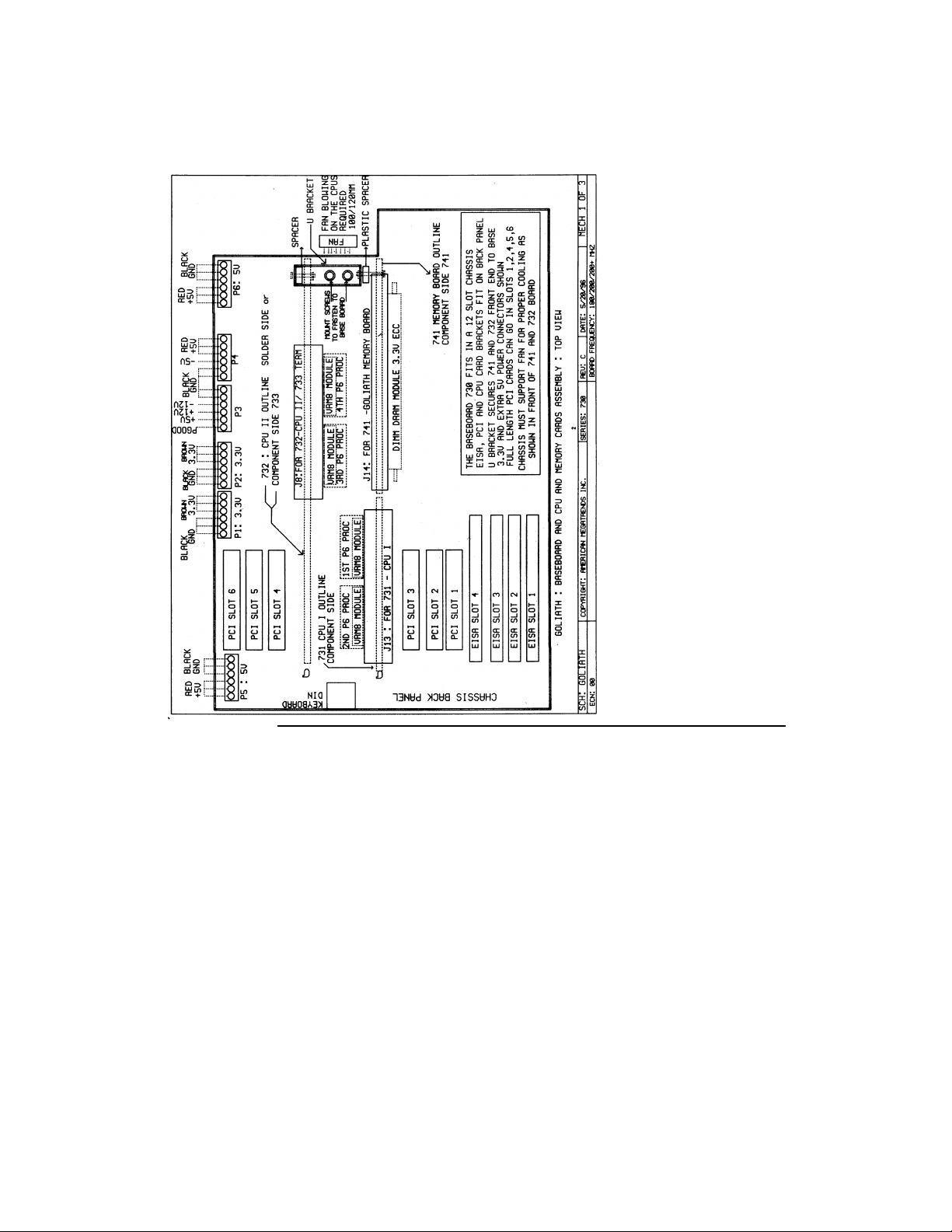
A Mechanical Drawings
Chapter 3 Programming the Flash ROM 73
Page 79
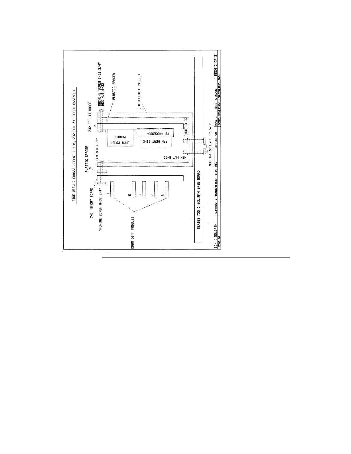
Goliath PCI Pentium Pro EISA System User’s Guide
74
Page 80
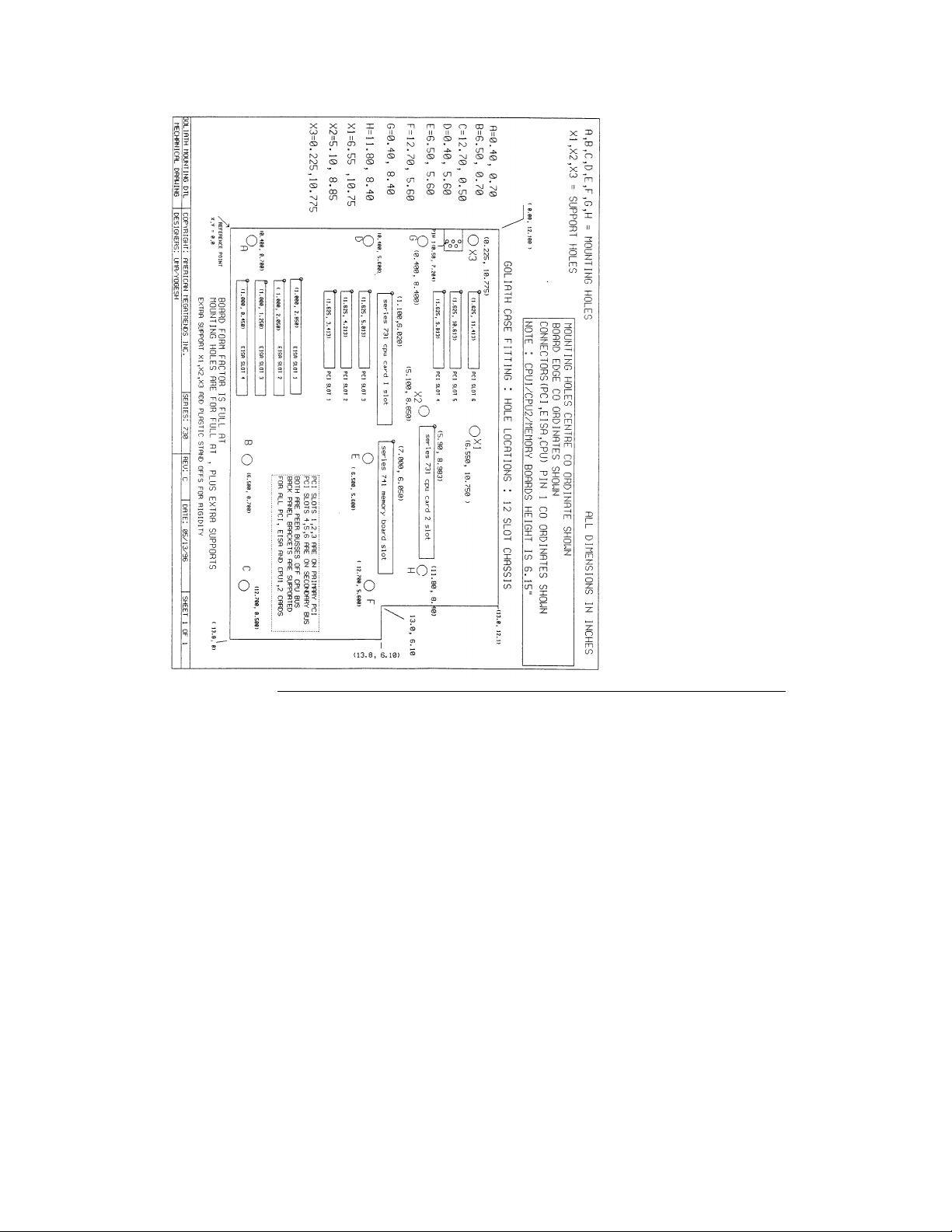
Chapter 3 Programming the Flash ROM 75
 Loading...