

Page 1
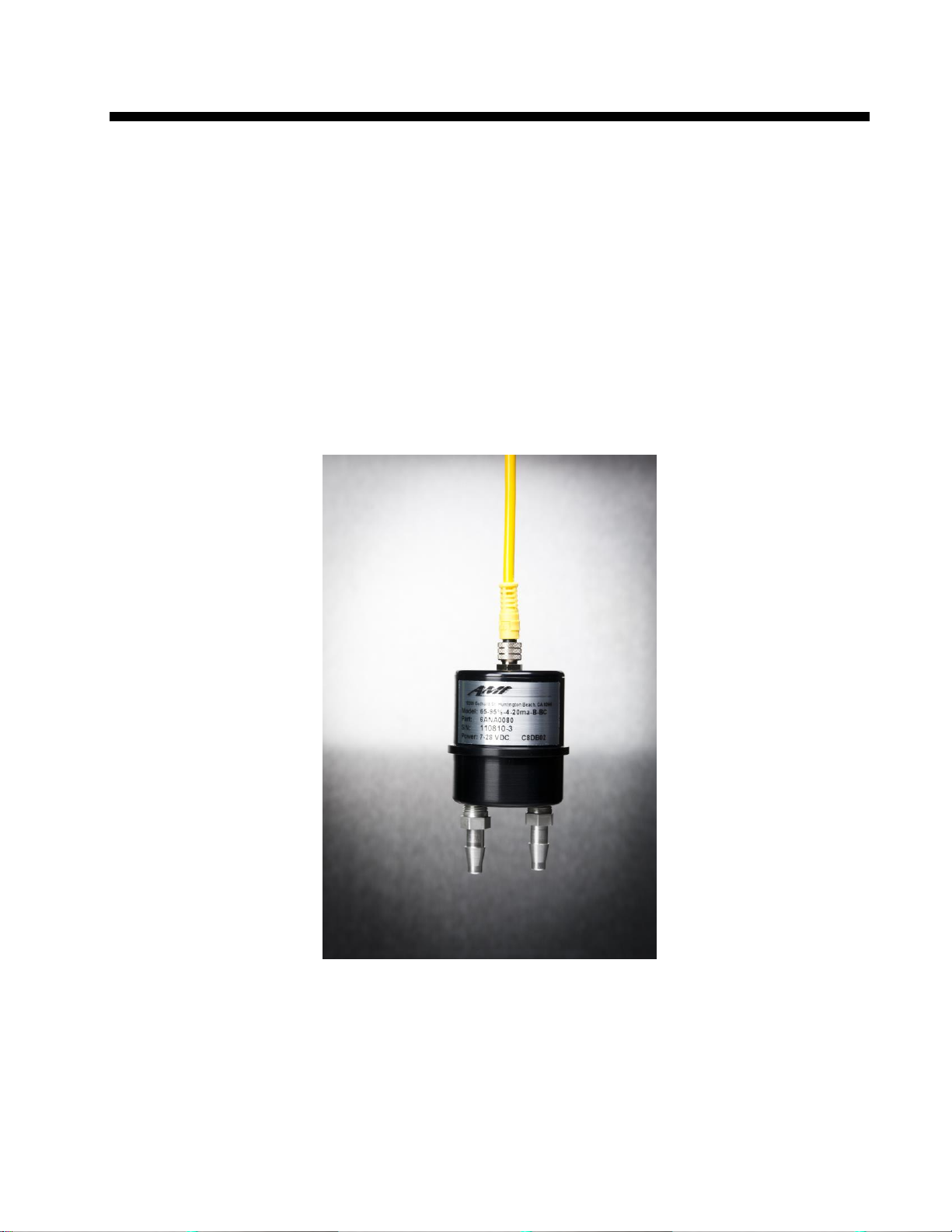
AMI
Oxygen Analyzer Manual
Model 65 Probe
AMI, Costa Mesa, CA
Page 2

Contents
Preface 4
The AMI Model 65 Oxygen Probe Analyzer 5
Caution 4
Address 4
Introduction 5
Features: 5
Options: 5
Oxygen sensor: 5
Gas compatibility 6
Sensor life 6
Sensor Warranty: 6
Instrument Warranty: 6
Installation and Operation 7
Receiving the analyzer 7
Precaution 7
Installation 7
Location: 7
Probe connection: 8
Display unit option: 9
Display unit connections: 10
Initial test: 10
Output connections: 10
Sample connection: 10
Sensor Installation: 10
Notes: 10
Operation 12
Calibration: 12
Maintenance and troubleshooting 13
Maintenance: 13
AMI Analyzer Manual 2
Page 3

Periodic Calibration: 13
Specifications and Disclaimer 14
Specifications: 14
Disclaimer 15
AMI Analyzer Manual 3
Page 4

Preface
The AMI series of analyzers provide the latest in high-definition oxygen analysis. The series includes trace
oxygen, percent oxygen and portable trace and percent oxygen models. Most of them share the same basic
design, using time proven oxygen sensors and advanced high definition electronics for noise and
interference free performance.
The Model 65 series are a set of extremely compact oxygen probes that contain a zirconium oxide sensor
and all associated electronics using an advanced microprocessor design. The basic models produce a linear
voltage output corresponding to either 0-25% oxygen, 0-50% oxygen or 0-95% oxygen. They require no
supporting electronics and are so stable that they can usually be installed and forgotten over their entire
life. The sensor is expected to last up to ten years in continuous operation, and indefinitely in storage. This
means that these units can be stored as spare parts for years and used immediately with no need for
replacing the sensor.
As options they can be supplied with either 4-20mA isolated output. An optional display unit can also be
supplied.
Caution
Read and understand this manual fully before attempting to use the instrument. In particular understand
the hazards associated with using flammable or poisonous gases, and associated with the contents of the
sensor used.
Address
Advanced Micro Instrument
225 Paularino Ave
Costa Mesa, CA 92626
www.AMIO2.com
(714) 848-5533
Last Revised: 08/31/2018
AMI Analyzer Manual 4
Page 5

The AMI Model 65 Oxygen Probe Analyzer
Introduction
The Advanced Micro Instruments Oxygen Probe is designed for monitoring of oxygen content in a nitrogen
or similar inert gas stream. It operates on a single range, normally 0-25% oxygen, and produces an output
typically 0-2.5V DC over this range. It uses 7 - 24V DC power, and it provides both a power and signal
ground for lower signal offset. No calibration is provided internally: calibration is performed either by the
host system to which it is attached or else by the optional meter display unit.
Features:
Percent oxygen in non-flammable samples
General purpose self-contained oxygen sensor
Extremely stable, long-life sensor
Virtually unaffected by temperature changes
Virtually unaffected by barometric pressure changes
Virtually unaffected by humidity changes
Virtually unaffected by flow rate changes
Calibration interval 6 months
Very small size
Standard 0-1V output
Isolated 4-20mA output optional
Very low cost
Options:
Display unit
0-50% range
0-95% range
4-20mA output
Diffusion screen
Barbed fittings
Compression fittings
Oxygen sensor:
AMI uses a unique zirconium oxide sensor. This sensor measures the concentration of oxygen in a gas
stream, using an oxygen specific chemistry. It generates an output current in proportion to the amount of
AMI Analyzer Manual 5
Page 6

oxygen present, and has zero output in the absence of oxygen, thus avoiding any requirement to zero the
analyzer. The cell is almost linear throughout its range, and a built-in microprocessor corrects the residual
non-linearity to better than 0.1%. The span calibration may be performed using standard span gases or
ambient air, but the sensor is so stable that calibration is ordinarily not necessary.
Percent level analyzers are routinely calibrated on air. Air has a reliable 20.94% oxygen in it, when dry. In
the case of its use as an area monitor it is advisable to use a known high quality air supply for calibration
since the room air may not contain 20.94% of oxygen! High range sensors should be calibrated with a gas
whose concentration is near the top of the range – 50% for the 0-50% unit, and 95% for the 0-95% unit.
Gas compatibility
The zirconium oxide sensor operates internally at red heat, with platinum as its electrodes. This means that
any oxidizable gases will react with any oxygen present and burn, reducing the apparent oxygen reading. It
also means that gases which can decompose at high temperatures will do so. In the case of Freons this can
produce hazardous byproducts. It also means that flammable mixtures of gases may be ignited. Sulfur
containing gases and acid gases such as SO2 will degrade the sensor and shorten its life.
DO NOT USE THIS PROBE WITH FLAMMABLE GASES OR HALOGEN CONTAINING
GASES!!
Sensor life
Unlike electrochemical sensors, the model 65 sensor does not degrade when it is not in use. Its life depends
on the total amount of oxygen to which it is exposed, while it is powered up. If it is powered continuously,
and exposed to air, the sensor will remain almost completely stable for about several years, and thereafter
will gradually drop its reading for the next few years. If it is run on an 8 hour duty cycle, it will last three
times as long. If it is run continuously at 5% oxygen, it will last at least 6 years before the sensor starts to
change. If it is run at 5% oxygen on an 8 hour duty cycle, it will last maybe 18 years before the sensor starts
to change.
Sensor Warranty:
The sensor is warranted to operate for at least two years, with an expected life of up to 10 years.
Instrument Warranty:
Any failure of material or workmanship will be repaired free of charge for a period of two years from the
original purchase (shipping date) of the instrument. AMI will also pay for one way shipment (back to the
user).
Any indication of abuse or tampering will void the warranty.
AMI Analyzer Manual 6
Page 7
Installation and Operation
Receiving the analyzer
Precaution
When you receive the instrument, check the package for evidence of damage and if any is found, contact
the shipper.
Installation
Location:
The probe may be installed in any orientation. Typically the gas connections are pointing downwards, but
this is not necessary.
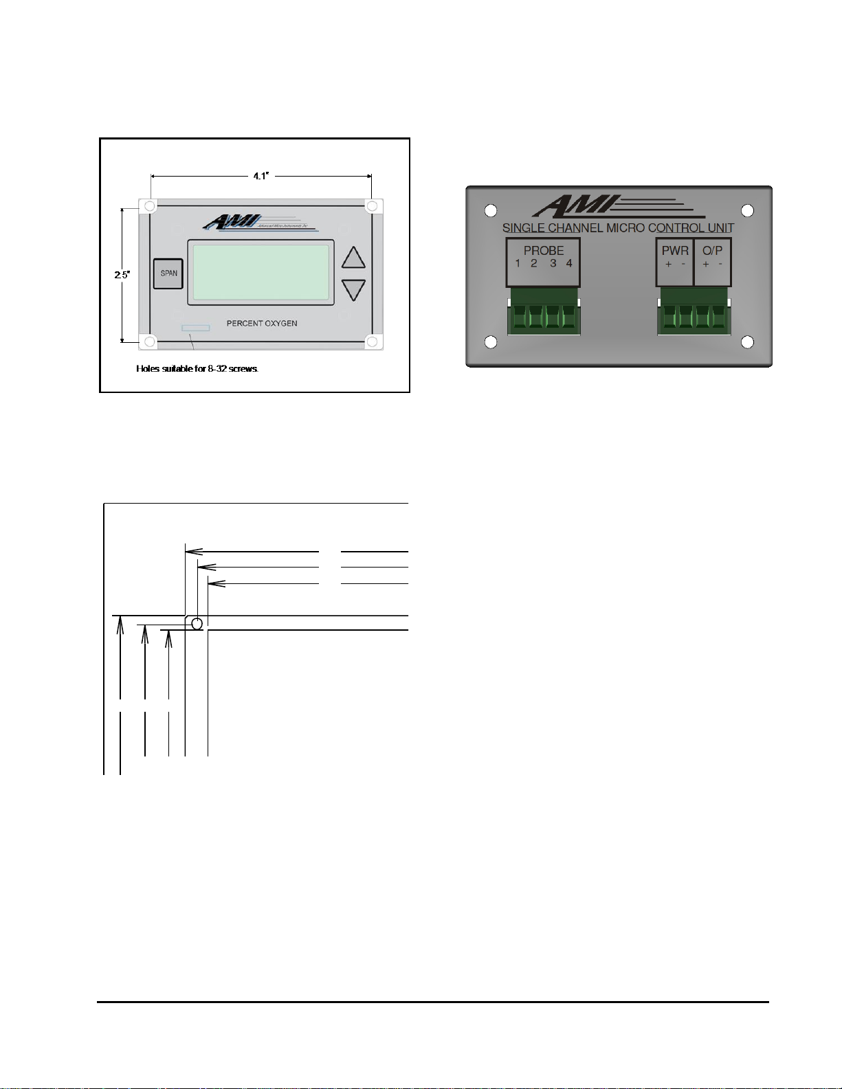
Mount the display unit (if used) in a suitable panel opening with 8-32 (or equivalent) screws. This unit
should be within about 6 feet of the probe if the voltage output probe is used, and can be virtually any
distance if the current output version is used..
Connect the cable provided to the probe and to the display unit, or suitable power supply (7-28V DC) and
monitoring system.
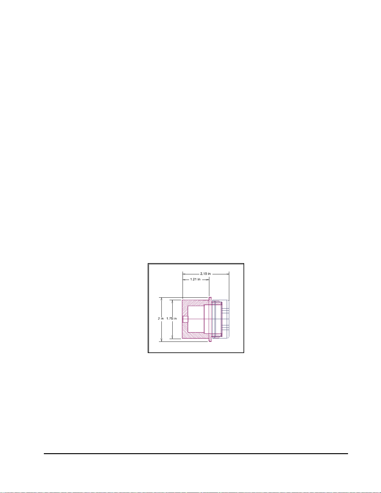
Figure 1. Probe dimensions
AMI Analyzer Manual 7
Page 8

Wire color
Connection
Brown
+7 to +28 VDC, 100 to 500mA
Black
Ground/Return
White
Voltage output
Blue
Signal ground
Probe connection:
(Probe mounted without display unit)
The unit requires a DC power supply between about 7 and 28 volts, at less than 500 mA. The actual current
consumption is greater at low voltages than high voltages, and is typically about 250mA at 12V. The supply
should be free of high frequency noise - if it is derived from a switching power supply it is advisable to use a
series inductor and parallel capacitors to filter it.
The probe is provided with a length of cable attached. If this length is not sufficient, an additional length
may be added up to a distance of about 100ft. However, make sure the wire gauge is adequate for the
current carried. Make the connection in a suitable connection box. The cable used must be a pair of
shielded twisted pairs.
Use the black wire for the ground return for the power supply, and use the blue wire as the ground
reference for the signal. This way the power supply current won’t generate an offset and noise due to the
resistance of the wiring used.
(Model 64 provides a 5V regulated output in place of the separate grounds.)
AMI Analyzer Manual 8
Page 9
Display unit option:
3.8
4.1
2.352.5
4.5
2.78
Figure 3. Back Panel Connections
Figure 4. Mounting Dimensions
Figure 2. Display unit showing mounting hole dimensions
AMI Analyzer Manual 9
Page 10

Display unit connections:
Back Panel Terminal
Probe Connection
Probe 1
Brown
Probe 2
Black
Probe 3
Blue
Probe 4
White
PWR+
+7-28V DC
PWR-
Ground
O/P+
4-20mA +
O/P-
4-20mA -
The Display unit is designed to be connected to the probe, and to provide a calibrated output signal. It
needs between 7 and 28V DC power as above, and uses the 5V supply from the probe as the power for its
meter. The first four connections are made to the probe; the second four are user connections.
Initial test:
Install the unit as desired, and connect it to some form of monitoring system. Turn on the power, and wait
for about 5 minutes for the sensor to warm up, and to stabilize.
Expose the unit to air, and calibrate the monitoring system to 20.94% oxygen (or equivalent nitrogen for
nitrogen purity systems). The unit should be recalibrated after about one day, and thereafter at a rate
determined by usage, though once every six months month is typical.
Output connections:
The voltage output circuit is capable of driving an input resistance of 10K Ohms or more. Lower input
resistances will degrade the accuracy of the circuit.
Sample connection:
The standard probe is provided with two barbed fittings. These are mounted into 1/8” NPT female orifices,
and so may be removed and appropriate compression fittings used instead. It may be desirable to provide a
tee in the line for calibration - see the discussion below. Sample flow rate should be between 0.1 SCFH and
10 SCFH, the exact amount not being critical. Avoid back-pressuring the sensor with excess flow if there is
any restriction on the exhaust. Optionally the probe may be supplied with a diffusion screen for area
monitoring use.
Sensor Installation:
The sensor is permanently mounted in the probe, and does not require separate installation.
Notes:
The unit is designed to be mounted on a suitable clip in a general purpose area. It is not suitable for
installation in a hazardous area though it may be mounted outdoors if the temperature range does not
exceed the -4°F to 122°F (–20°C - 50°C) for which it is rated. The cable supplied is approximately 6 ft. long.
AMI Analyzer Manual 10
Page 11

Do not mount it close to sources of electrical interference such as large transformers, motor start
contactors, relays etc. Also avoid subjecting it to significant vibration. Make sure that the sensor cable
does not run next to high-current cables, or AC cables. Preferably the sensor cable should be in its own
conduit.
If used as an area monitor the probe should be mounted where it will sense a representative sample of the
room air. If the room has no natural circulation, you may want to install a fan to make sure that there is
some air movement. The nature of the possible asphyxiating gas also should affect its placement - if the
danger is from a heavy gas such as CO2, the sensor should be mounted low down so that it detects the gas
before people start breathing it, while if the gas is light such as helium, the sensor should be mounted
higher. Otherwise it should normally be mounted at head height.
DO NOT USE THIS PROBE WITH HALOGEN CONTAINING GASES SUCH AS
FREONS!
AMI Analyzer Manual 11
Page 12

Operation
Calibration:
The sensor will stabilize within a few minutes, and the probe may be calibrated almost as soon as it has
been installed.
Probe only option:
No provision is made in the probe itself for calibration. It is expected that the display or monitoring device
will perform this function. The output of the sensor will be very close to 2.09V on air, and may not need
further calibration. The following section is intended to provide tips on performing calibration if necessary.
Display option:
Use the Span button with the Up/down arrows provided on the display unit to calibrate the output. Expose
the probe to air (or about 50% or 95% oxygen for the mid or high range versions), and adjust the up/down
arrows until the meter reads the correct value (20.9% or 50% or 95.0%). The voltage output will then be
calibrated to 1V full scale.
Be absolutely sure that you are using at least a certified, and preferably a primary standard span gas
supply as the span gas. Alternatively use known fresh air. So called "Manufactured air" or bottled
compressed air often has an oxygen content that is significantly different from its label.
If the calibration is to be performed in software, bear in mind the following points.
1. The most common error is that the user attempts to span the system on an incorrect gas, often
nitrogen. Some limitation must be made therefore in the permissible gain of the system so that this
condition is detected. Typically the gain is allowed to vary no more than 25% between calibrations.
However it is still possible for a calibration to be sufficiently in error that the system cannot be
recalibrated again once it has been messed up. Therefore it must be possible to force a calibration no
matter the apparent error.
2. The calibration routine should detect an excessive drift and delay calibration until the drift has stopped,
or abort the process if no good reading can be obtained. This might happen because of an inadequate
calibration gas flow, due perhaps to an empty cylinder.
3. The calibration routine should allow at least 60 seconds for the reading to stabilize.
4. If the system performs an automatic calibration, some means of alerting the user to calibration failure
must be made.
AMI Analyzer Manual 12
Page 13

Maintenance and troubleshooting
Maintenance:
The AMI oxygen probe is maintenance free other than for periodic calibration.
Periodic Calibration:
The probe should be calibrated about once every six months to obtain the best accuracy. The sensor will
remain stable for several years depending on the application, and then degrade at the rate of about 1% a
month if it is operated continuously. Use in a particularly aggressive environment may degrade the sensor
faster: in this case calibrate more often.
AMI Analyzer Manual 13
Page 14

Specifications and Disclaimer
Specifications:
Standard ranges:
Single range: 0 - 25% (0 – 50%, 0 - 95% optional).
Sensitivity: 0.5% of full scale.
Repeatability: +/- 1% of full scale at constant temperature.
Operating temperature: -4°F to 122°F (-20°C - 50C).
Humidity: < 85%, non-condensing.
Operational conditions: Pollution degree 2, Installation category I I.
Drift: < +/- 1% of full scale in 4 weeks at constant temperature.
Response time:
90% of full scale < 13 seconds.
Outputs: 0 - 2.5 VDC (4-20mA optional).
Power requirements: Between 7 and 28 VDC (nominally 24VDC) Typically 250 mA at 12Vwith no
external draw from the 5V supply. Current draw is higher at lower voltage and lower at higher
voltage.
Dimensions: 2.15 Dia. x 2" high (not including fittings or leads).
Weight: less than 1 lb.
Warranty: 2 years parts and labor.
Sensor warranty: 2 years.
AMI Analyzer Manual 14
Page 15

Disclaimer
Although every effort has been made to assure that the AMI analyzers meet all their performance
specifications, AMI takes no responsibility for any losses incurred by reason of the failure of its analyzers or
associated components. AMI’s obligation is expressly limited to the analyzer itself.
In particular, the AMI analyzer is designed for operation with non-flammable samples in a general purpose,
i.e. non-hazardous area. Any damage resulting from its use in a hazardous area or with flammable or
explosive samples is expressly the responsibility of the user.
The AMI analyzer is not designed as a primary safety device, that is to say it is not to be used as the primary
means of assuring personnel safety. In particular it is not designed to act as a medical instrument,
monitoring breathing air for correct oxygen concentration, and should not be used as such when it is the
only safety device on the gas system.
AMI Analyzer Manual 15
 Loading...