

AMG AMG9024GM-HP-H-2S4C-R, AMG9024GM-H-2S4C-R, AMG9024GM-HP-H-2S2I8C-R, AMG9024GM-HP-H-VE-R, AMG9024GM-H-2S2I8C-VE-R User Manual
...
AMG
9IM2x/9HM2x User Manual
User Manual AMG 9IM2x/9HM2x
Version No : 2.1.5.3
© Copyright AMG Systems Ltd 2015-2017. All rights reserved. All other trademarks and copyrights
referred to herein are the property of their respective holders. No part of this documentation may be
reproduced in any form or by any means or used to make any derivative work, without written
permission from the copyright holder, details of whom can be obtained from AMG Systems Ltd. This
document is subject to change without written prior notice. Whilst AMG Systems Ltd makes every
effort to ensure the accuracy and reliability of the information contained in this document, its
9IM2X/9HM2X USER MANUAL 1
© AMG SYSTEMS CONFIDENTIAL & PROPRIETARY.

AMG SYSTEMS LTD.
employees and Agents will not be responsible for any loss, however arising, from the use of, or
reliance on, this information.
Legal Notice: Parts of this product are protected by patents.
Electromagnetic Compatibility (EMC)
This is a Class B product.
Manufacturer’s Declaration of Conformance
A Declaration of Conformity in accordance with the following EU standards has been made and is kept
on file at the address shown on the last page.
The manufacturer declares that the product supplied with this document is compliant
with the provisions of the EMC Directive 2014/30/EU, the Low Voltage Directive LVD
2006/95/EC and the CE Marking Regulation 768/2008/EC & Decision 765/2008.
This device complies with Part 15 of the FCC Rules.
Operation of this product is subject to the following two conditions:
This device may not cause harmful interference.
This device must accept any interference received, including interference that may
cause undesired operation.
ICES-003
This Class B digital apparatus meets all requirements of the Canadian Interference causing equipment
regulations.
Cet appareil numérique de la Classe B Respecte toutes les exigences du Règlement sur le matérial
rouiller du Canada.
USER MANUAL AMG 9IM2X/9HM2X 2

1 : INTRODUCTION
Before You Begin
Read these instructions carefully before installing or operating this product.
Note: This equipment should be installed by a qualified service person and should conform to local
and national regulations.
This manual provides installation and operation information. To use this document you must have the
following minimum qualifications
A basic knowledge of Ethernet, Ethernet Switches and Layer2 networking.
A basic knowledge of electrical wiring and low-voltage electrical connection.
Intended Use
Use this product only for the purpose for which it was designed, as described in this manual.
Warning:
Improper use of this equipment can cause severe bodily injury or equipment damage
Environmental Conditions
Storage: -45° to +85° C. The switch should be allowed to acclimatize to its operational temperature
range before power is supplied. Additionally, if the switch is moved from a colder area to a warmer
area, precautions should be taken to ensure that condensation is prevented.
Operational: -40° to +74° C.
Customer Support
For assistance in installing, operating, maintaining and troubleshooting this product, please refer to
this document and any other documentation provided. If you still require assistance, please contact
AMG Systems at the address shown on the last page
9IM2X/9HM2X USER MANUAL 3

AMG SYSTEMS LTD.
Document
Rev No.
Change Description
Author
Date
2.0.0.5
Draft
M.I.Steval
22-04-2016
2.0.0.6
1. New non-TFTP s/w upgrade feature.
2. Updated screen-capture examples
M.I.Steval
16-06-2016
2.0.0.b7
Beta7 Release
M.I.Steval
01/07/2016
2.0.0.b8
1. Clarification of configuration in var sections
2. Added SFP transceivers section
M.I.Steval
13/07/2016
2.0.0.b9
1. Corrected rear panel DC power options
2. Clarification of configuration in various sections
3. IPv4 Default DHCP settings
4. Details of Syslog Traps and Messages
5. ECFM Module documentation added.
6. Updated EMC Directive Spec.
7. Static Unicast / Multicast Address added.
8. Updated LLDP section
M.I.Steval
08/09/2016
2.0.0
Release version
1. Management feature : additional user / password.
2. Updated screen captures VLANs, LLDP, RSTP
3. Updated Save and Restore section.
M.I.Steval
13/10/2016
2.1.0
Release version for 9IM2x/9HM2x platform
Provisional.
M.I.Steval
11/01/2017
2.1.1
Unreleased draft feature updates
M.I.Steval
23/02/2017
2.1.4
1. Additional Features :
DHCP Server
IGMP Snooping
Jumbo Frame Support
High Speed I/O
2. Updated Screenshots.
3. Added 240W info.
M.I.Steval
19/07/2017
2.1.4.1
1. Correction VLAN Chapter heading missing.
2. Minor corrections to RSTP & MSTP configuration.
3. Carifications in SNMP Trap Manager configuration.
M.I.Steval
10/08/2017
2.1.5.3
1. User definable management VLAN.
2. SFP Transceiver Diagnostics
M.I.Steval
30/10/2017
Change History
USER MANUAL AMG 9IM2X/9HM2X 4

1 : INTRODUCTION
Contents
CHAPTER 1: INTRODUCTION _____________________________________________ 19
1.1 AMG 9IM2X/9HM2X MODELS ............................................................... 20
1.2 AMG9IM2-8G-2S ................................................................................. 21
1.3 AMG91IM2-4FH-1S-4S16C ................................................................ 21
1.4 AMG91IM2-20GH-5S-4S16C-P240 .................................................... 22
CHAPTER 2: HARDWARE DESCRIPTION ____________________________________ 23
2.1 MANAGEMENT CONSOLE ........................................................................ 24
2.2 ETHERNET CONNECTIONS ...................................................................... 25
2.3 I/O CONNECTIONS ................................................................................. 26
2.4 PIN LAYOUT OF I/O CONNECTORS .......................................................... 27
2.5 POWER CONNECTOR ............................................................................. 28
2.6 POWER OVER ETHERNET ....................................................................... 29
2.7 ETHERNET PORT LEDS ......................................................................... 30
2.8 I/O PORT LEDS ..................................................................................... 31
CHAPTER 3: HS-IO HARDWARE DESCRIPTION ______________________________ 32
3.1 HS-IO CONNECTIONS ............................................................................ 33
3.2 HS-IO FRONT PANEL LEDS ................................................................... 34
3.3 HS-IO DATA CHANNEL INTERFACE ......................................................... 35
3.4 HS-IO CONTACT CLOSURE INTERFACE .................................................. 36
CHAPTER 4: INSTALLATION GUIDE ________________________________________ 38
4.1 UNPACKING THE SWITCH........................................................................ 39
4.2 INSTALLING PRE-REQUISITES ................................................................. 39
4.3 MOUNTING THE SWITCH ......................................................................... 39
4.4 POWER CONNECTIONS .......................................................................... 40
4.5 CONNECTING TO NETWORK .................................................................... 41
4.6 CONNECTING TO RS-232 MANAGEMENT CONSOLE ................................. 42
CHAPTER 5: WEB INTERFACE CONVENTIONS ______________________________ 44
5.1 WEB INTERFACE ................................................................................... 45
5.2 INTERNET EXPLORER SETTINGS ............................................................. 47
5.3 DOCUMENT CONVENTIONS ..................................................................... 48
CHAPTER 6: LOGGING INTO AMG 9IM2X/9HM2X _____________________________ 49
6.1 LOGIN ................................................................................................... 50
6.2 HOME SCREEN ...................................................................................... 51
CHAPTER 7: LEFT NAVIGATION PANE _____________________________________ 53
7.1 SYSTEM ................................................................................................ 54
7.2 LAYER2 MANAGEMENT .......................................................................... 55
7.3 IP MANAGEMENT ................................................................................... 56
7.4 MULTICAST ............................................................................................ 57
7.5 I/O MANAGEMENT .................................................................................. 58
7.6 STATISTICS ........................................................................................... 59
CHAPTER 8: SYSTEM INFORMATION ______________________________________ 60
8.1 SYSTEM INFORMATION ........................................................................... 61
CHAPTER 9: USER MANAGEMENT ________________________________________ 64
9.1 USER MANAGEMENT .............................................................................. 65
CHAPTER 10: SAVE AND RESTORE _________________________________________ 67
10.1 SAVE CONFIGURATION ........................................................................... 68
10.2 RESTORE CONFIGURATION .................................................................... 70
10.3 FILE DOWNLOAD .................................................................................... 71
CHAPTER 11: SOFTWARE UPGRADE _______________________________________ 73
11.1 SOFTWARE UPGRADE ............................................................................ 74
CHAPTER 12: REBOOT ___________________________________________________ 76
9IM2X/9HM2X USER MANUAL 5

AMG SYSTEMS LTD.
12.1 REBOOT ................................................................................................ 77
CHAPTER 13: SNTP ______________________________________________________ 78
13.1 SNTP GLOBAL CONFIGURATION ............................................................ 79
13.2 SNTP UNICAST MODE CONFIGURATION ................................................. 82
CHAPTER 14: HTTP ______________________________________________________ 84
14.1 HTTP SESSION TIMEOUT ....................................................................... 85
CHAPTER 15: SNMP ______________________________________________________ 86
15.1 SNMP AGENT CONTROL SETTINGS ........................................................ 87
15.2 SNMP GLOBAL CONFIGURATION............................................................ 88
15.3 SNMP AGENT CONFIGURATION ............................................................. 90
15.3.1.1 SNMP Community Settings ------------------------------------------------ 91
15.3.1.2 SNMP Group Settings ------------------------------------------------------- 93
15.3.1.3 SNMP Group Access Settings -------------------------------------------- 95
15.3.1.4 SNMP View Tree Settings -------------------------------------------------- 97
15.3.1.5 SNMP Target Address Settings ------------------------------------------- 99
15.3.1.6 SNMP Target Parameter Settings --------------------------------------- 101
15.3.1.6.1 SNMP Filter Profile Settings ------------------------------------------ 103
15.3.1.7 SNMP User Security Settings -------------------------------------------- 105
15.3.1.8 SNMP Trap Manager Settings ------------------------------------------- 107
15.3.1.9 SNMP Filter Settings ------------------------------------------------------- 109
15.4 SNMP PROXY ..................................................................................... 111
15.4.1 SNMP Proxy Settings ..................................................................... 112
15.4.2 SNMP MIB Proxy Settings .............................................................. 114
CHAPTER 16: PORT MANAGER ___________________________________________ 116
16.1 PORT MANAGER BASIC SETTINGS ........................................................ 117
16.2 PORT MANAGER PORT CONTROL ......................................................... 119
16.3 PORT MANAGER TRANSCEIVERS .......................................................... 122
CHAPTER 17: VLAN _____________________________________________________ 123
17.1 VLAN GLOBAL SETTINGS .................................................................... 124
17.2 VLAN PORT SETTINGS ........................................................................ 126
17.3 VLAN STATIC CONFIGURATION ............................................................ 128
CHAPTER 18: ADDRESS TABLES __________________________________________ 130
18.1 ADDRESS TABLES MAC TABLE ............................................................ 131
18.2 ADDRESS TABLES STATIC UNICAST ENTRIES ........................................ 134
18.3 ADDRESS TABLES STATIC MULTICAST ENTRIES .................................... 135
CHAPTER 19: MSTP _____________________________________________________ 136
19.1 MSTP GLOBAL CONFIGURATION .......................................................... 137
19.2 MSTP TIMERS .................................................................................... 141
19.3 MSTP PORT CONFIGURATION .............................................................. 143
19.4 MSTP VLAN MAPPING ....................................................................... 148
19.5 MSTP PORT SETTINGS ....................................................................... 150
19.6 MSTP CIST PORT STATUS ................................................................. 152
19.7 MSTP BRIDGE PRIORITY ..................................................................... 155
CHAPTER 20: RSTP _____________________________________________________ 157
20.1 RSTP GLOBAL CONFIGURATION .......................................................... 158
20.2 RSTP BASIC SETTINGS ....................................................................... 161
20.3 RSTP PORT SETTINGS ........................................................................ 163
20.4 RSTP PORT STATUS ........................................................................... 168
CHAPTER 21: LLDP _____________________________________________________ 170
21.1 LLDP GLOBAL CONFIGURATIONS ......................................................... 171
21.1.1 LLDP Configured Traces ................................................................ 172
21.2 LLDP BASIC SETTINGS ........................................................................ 174
21.3 LLDP INTERFACES SETTINGS .............................................................. 176
21.4 LLDP NEIGHBOUR INFORMATION ......................................................... 178
21.5 LLDP AGENT INFO .............................................................................. 179
21.6 LLDP AGENT DETAILS ......................................................................... 180
USER MANUAL AMG 9IM2X/9HM2X 6

1 : INTRODUCTION
CHAPTER 22: 802.1X ____________________________________________________ 184
22.1 802.1X GLOBAL SETTINGS ................................................................... 185
22.1.1 802.1x PNAC Traces ...................................................................... 187
22.2 802.1X PORT SETTINGS ...................................................................... 188
22.3 802.1X TIMER CONFIGURATION ........................................................... 194
22.4 802.1X LOCAL AUTHENTICATION SERVER CONFIGURATION ................... 196
22.5 802.1X RADIUS SERVER CONFIGURATION .......................................... 198
22.5.1 802.1x RADIUS Traces .................................................................. 200
22.6 802.1X MAC SESSION INFO ................................................................. 201
CHAPTER 23: IP MANAGEMENT ___________________________________________ 203
23.1 IPV4 INTERFACE SETTINGS .................................................................. 204
23.2 IPV4 IP ROUTE CONFIGURATION .......................................................... 206
CHAPTER 24: DHCP SERVER _____________________________________________ 208
24.1 DHCP BASIC SETTINGS ....................................................................... 210
24.2 DHCP POOL SETTINGS ....................................................................... 211
24.3 DHCP POOL OPTION SETTINGS ........................................................... 213
24.4 DHCP SERVER IP EXCLUDE SETTINGS ................................................ 214
24.5 DHCP HOST IP SETTINGS ................................................................... 216
24.6 DHCP HOST OPTION SETTINGS ........................................................... 217
24.7 DHCP POOL OPTIONS : APPENDIX A .................................................... 219
CHAPTER 25: IGMP SNOOPING ___________________________________________ 229
25.1 IGMP SNOOPING CONFIGURATION ....................................................... 230
25.2 IGMP SNOOPING TIMER SETTINGS ...................................................... 234
25.3 IGMP SNOOPING VLAN CONFIGURATION............................................. 236
25.4 IGMP SNOOPING INTERFACE CONFIGURATION ..................................... 239
25.5 IGMP SNOOPING VLAN ROUTER PORT CONFIGURATION ...................... 241
25.6 IGMP SNOOPING VLAN ROUTER PORTS ............................................. 242
25.7 IGMP SNOOPING STATIC CONFIGURATION ........................................... 243
25.8 IGMP SNOOPING MAC / IP BASED MULTICAST FORWARDING TABLE ..... 244
CHAPTER 26: TAC ______________________________________________________ 246
26.1 TAC PROFILE CONFIGURATION ............................................................ 247
26.1.1 TAC Traces ..................................................................................... 249
26.2 TAC PROFILE FILTER CONFIGURATION ................................................. 250
CHAPTER 27: SERIAL DATA I/O ___________________________________________ 252
27.1 SERIAL DATA APPLICATIONS ................................................................ 253
27.2 SERIAL DATA PORT CONFIGURATION .................................................... 255
27.3 SERIAL DATA IP CONFIGURATION ......................................................... 256
27.4 SERIAL DATA EXAMPLE A : POINT-TO-POINT ......................................... 258
27.5 SERIAL DATA EXAMPLE B : MULTIPLE POINT-TO-POINT .......................... 260
27.6 SERIAL DATA EXAMPLE B : POINT-TO-MULTIPOINT ................................. 264
CHAPTER 28: CONTACT CLOSURE I/O OVER IP _____________________________ 267
28.1 CONTACT CLOSURES APPLICATIONS .................................................... 268
28.2 CONTACT CLOSURE CONFIGURATION ................................................... 268
28.4 CONTACT CLOSURE EXAMPLE A : POINT-TO-POINT ............................... 270
28.5 CONTACT CLOSURE EXAMPLE B : MULTIPLE POINT-TO-POINT ................ 271
28.6 CONTACT CLOSURE EXAMPLE C : POINT-TO-MULTIPOINT ...................... 275
28.7 CONTACT CLOSURE EXAMPLE D : MULTIPOINT-TO-POINT ...................... 279
CHAPTER 29: HIGH-SPEED IO PORTS ______________________________________ 284
29.1 HS-IO GLOBAL CONFIGURATION .......................................................... 285
29.2 HS-IO SERIAL PORTS CONFIGURATION ................................................ 286
29.3 HS-IO SERIAL I/P CONFIGURATION ...................................................... 287
CHAPTER 30: INTERFACE STATISTICS _____________________________________ 289
30.1 CLEAR INTERFACE STATISTICS ............................................................. 289
30.2 INTERFACE STATISTICS ........................................................................ 290
30.3 ETHERNET STATISTICS ........................................................................ 290
CHAPTER 31: MSTP STATISTICS __________________________________________ 291
9IM2X/9HM2X USER MANUAL 7

AMG SYSTEMS LTD.
31.1 MSTP INFORMATION ........................................................................... 292
31.2 MSTP CIST PORT STATISTICS ............................................................ 292
31.3 MSTP MSTI PORT STATISTICS ............................................................ 293
CHAPTER 32: RSTP STATISTICS __________________________________________ 294
32.1 RSTP INFORMATION ............................................................................ 295
32.2 RSTP PORT STATISTICS ...................................................................... 295
CHAPTER 33: LLDP STATISTICS __________________________________________ 297
33.1 LLDP TRAFFIC INFORMATION ............................................................... 298
33.2 LLDP STATISTICS INFORMATION .......................................................... 299
33.3 LLDP ERROR INFORMATION ................................................................ 299
CHAPTER 34: 802.1X STATISTICS _________________________________________ 300
34.1 802.1X SESSION STATISTICS ............................................................... 301
34.2 802.1X SUPPLICANT SESSION STATISTICS ............................................ 301
34.3 802.1X MAC SESSION STATISTICS ....................................................... 302
CHAPTER 35: RADIUS SERVER STATISTICS ________________________________ 303
CHAPTER 36: IGMP SNOOPING STATISTICS ________________________________ 304
36.1 IGMP SNOOPING CLEAR STATISTICS ................................................... 305
36.2 IGMP SNOOPING V1/V2 STATISTICS .................................................... 305
36.3 IGMP SNOOPING V3 STATISTICS ......................................................... 306
CHAPTER 37: IP STATISTICS _____________________________________________ 307
37.1 IPV4 ARP CACHE STATISTICS ............................................................. 308
37.2 IPV4 ICMP STATISTICS ....................................................................... 308
CHAPTER 38: SNMP STATISTICS __________________________________________ 309
USER MANUAL AMG 9IM2X/9HM2X 8

Figures
Figure 1-1 : 9IM2-8G-2S .............................................................................................................................. 21
Figure 1-2 : 91IM2-4FH-1S-4S16C ............................................................................................................. 21
Figure 1-3 : 91IM2-20GH-5S-4S16C-P240 ................................................................................................. 22
Figure 2-1 : Console Adaptor / Cable .......................................................................................................... 24
Figure 2-2 : RJ45 Ethernet Ports ................................................................................................................. 25
Figure 2-3 : SFP Transceiver Ports ............................................................................................................. 25
Figure 2-4 : I/O Connections ....................................................................................................................... 26
Figure 2-5 : PoE Power Connections .......................................................................................................... 29
Figure 2-6 : Non PoE Power Connections................................................................................................... 29
Figure 2-7 : Ethernet Port LEDs .................................................................................................................. 30
Figure 2-8 : SFP Transceiver Port LEDs ..................................................................................................... 31
Figure 2-9 : I/O Port LEDs ........................................................................................................................... 31
Figure 3-1 : HS-IO Serial Data Interface Connections ................................................................................ 36
Figure 4-1 : Mounting the unit - DIN Rail ..................................................................................................... 40
Figure 4-2 : Mounting the unit - Surface ...................................................................................................... 40
Figure 4-3 : DC Power Connection .............................................................................................................. 41
Figure 4-4 : Network Connections ............................................................................................................... 42
Figure 4-5 : Console Connections ............................................................................................................... 42
Figure 4-6 : Login through CLI ..................................................................................................................... 43
Figure 5-1 : Web GUI screen sample 1 ....................................................................................................... 45
Figure 5-2 : Web GUI screen sample 2 ....................................................................................................... 46
Figure 5-3 : Browser General Settings Tab ................................................................................................. 47
Figure 5-4 : Browser History Settings .......................................................................................................... 47
Figure 6-1 : Login Screen ............................................................................................................................ 50
Figure 6-2 : Home Screen ........................................................................................................................... 51
Figure 7-1 : System Information Home Page .............................................................................................. 54
Figure 7-2 : Layer2 Management Home Page ............................................................................................ 55
Figure 7-3 : IP Management Home Page .................................................................................................... 56
Figure 7-4 : Multicast Home Page ............................................................................................................... 57
Figure 7-5 : I/O Management Home Page .................................................................................................. 58
Figure 7-6 : Statistics Home Page ............................................................................................................... 59
Figure 8-1 : System Information .................................................................................................................. 61
Figure 9-1 : User Management .................................................................................................................... 65
Figure 10-1 : Save configuration ................................................................................................................. 68
Figure 10-2 : Restore configuration ............................................................................................................. 70
Figure 10-3 : File Download ........................................................................................................................ 71
Figure 11-1 : Software Upgrade .................................................................................................................. 74
Figure 11-2 : Software Upgrade : File Upload in Progress.......................................................................... 75
Figure 11-3 : Software Upgrade : File Upload Completed .......................................................................... 75
Figure 12-1 : Rebooting the System ............................................................................................................ 77
Figure 13-1 : SNTP Global Configuration .................................................................................................... 79
Figure 13-2 : SNTP Unicast Mode Configuration ........................................................................................ 82
Figure 14-1 : HTTP Session Timeout .......................................................................................................... 85
Figure 15-1 : SNMP Agent Control Settings ................................................................................................ 87
Figure 15-2 : SNMP Basic Settings ............................................................................................................. 88
Figure 15-3 : SNMP Community Settings.................................................................................................... 91
Figure 15-4 : SNMP GROUP Settings......................................................................................................... 93
Figure 15-5 : SNMP Group Access Settings ............................................................................................... 95
Figure 15-6 : SNMP View Tree Settings...................................................................................................... 97
Figure 15-7 : SNMP Target Address Settings ............................................................................................. 99
Figure 15-8 : SNMP Target Parameter Settings ....................................................................................... 101
Figure 15-9 : SNMP Filter Profile Settings ................................................................................................ 103
9IM2X/9HM2X USER MANUAL 9
© AMG SYSTEMS CONFIDENTIAL & PROPRIETARY.

AMG SYSTEMS LTD.
Figure 15-10 : SNMP User Security Settings ............................................................................................ 105
Figure 15-11 : SNMP Trap Manager Settings ........................................................................................... 107
Figure 15-12 : SNMP Filter Settings .......................................................................................................... 109
Figure 15-13 : SNMP Proxy Settings ......................................................................................................... 112
Figure 15-14 : SNMP MIB Proxy Settings ................................................................................................. 114
Figure 16-1 : Port Manager Basic Settings ............................................................................................... 117
Figure 16-2 : Port Manager Port Control ................................................................................................... 119
Figure 16-3 : Port Manager Tranceivers.................................................................................................... 122
Figure 17-1 : VLAN Global Settings .......................................................................................................... 124
Figure 17-2 : VLAN Port Settings .............................................................................................................. 126
Figure 17-3 : Static VLAN Configuration ................................................................................................... 128
Figure 18-1 : Address Tables MAC Table : VLAN ID ................................................................................ 131
Figure 18-2 : Address Tables MAC Table : MAC address ........................................................................ 132
Figure 18-3 : Address Tables MAC Table : Port ....................................................................................... 132
Figure 18-4 : Address Tables MAC Table : All .......................................................................................... 133
Figure 18-5 : Address Tables Static Unicast Entries ................................................................................. 134
Figure 18-6 : Address Tables Static Multicast Entries ............................................................................... 135
Figure 19-1 : MSTP Global Configuration ................................................................................................. 137
Figure 19-2 : MSTP Timers Configuration ................................................................................................. 141
Figure 19-3 : MSTP Port Configuration ..................................................................................................... 143
Figure 19-4 : MSTP VLAN Mapping .......................................................................................................... 148
Figure 19-5 : MSTP Port Settings .............................................................................................................. 150
Figure 19-6 : MSTP CIST Port Status ....................................................................................................... 152
Figure 19-7 : MSTP Bridge Priority ............................................................................................................ 155
Figure 20-1 : RSTP Global Configuration .................................................................................................. 158
Figure 20-2 : RSTP Basic Settings ............................................................................................................ 161
Figure 20-3 : RSTP Port Settings .............................................................................................................. 163
Figure 20-4 : RSTP Port Status ................................................................................................................. 168
Figure 21-1 : LLDP Global Configurations................................................................................................. 171
Figure 21-2 : LLDP Configured Traces...................................................................................................... 172
Figure 21-3 : LLDP Basic Settings ............................................................................................................ 174
Figure 21-4 : LLDP Interface Settings ....................................................................................................... 176
Figure 21-5 : LLDP Neighbor Information.................................................................................................. 178
Figure 21-6 : LLDP Agent Info ................................................................................................................... 179
Figure 21-7 : LLDP Agent Details Part A ................................................................................................... 180
Figure 21-8 : LLDP Agent Details Part B ................................................................................................... 180
Figure 22-1 : 802.1x Global Settings ......................................................................................................... 185
Figure 22-2 : 802.1x PNAC Traces ........................................................................................................... 187
Figure 22-3 : 802.1x Port Settings Part A .................................................................................................. 188
Figure 22-4 : 802.1x Port Settings Part B .................................................................................................. 188
Figure 22-5 : 802.1x Timer Configuration .................................................................................................. 194
Figure 22-6 : 802.1x Local Authentication Server Configuration ............................................................... 196
Figure 22-7 : 802.1x Radius Server Configuration .................................................................................... 198
Figure 22-8 : 802.1x Radius Traces .......................................................................................................... 200
Figure 22-9 : 802.1x Mac Session Info ...................................................................................................... 201
Figure 23-1 : IPv4 Interface Settings ......................................................................................................... 204
Figure 23-2 : IPv4 IP Route Configuration ................................................................................................ 206
Figure 23-3 : IPv4 IP Route Configuration : Gateway ............................................................................... 207
Figure 24-1: DHCP Basic Settings ............................................................................................................ 210
Figure 24-2: DHCP Pool Settings .............................................................................................................. 211
Figure 24-3: DHCP Pool Options Settings ................................................................................................ 213
Figure 24-4: DHCP Server IP Exclude Settings ........................................................................................ 214
Figure 24-5: DHCP Host IP Settings ......................................................................................................... 216
Figure 24-6: DHCP Host Option Settings .................................................................................................. 217
Figure 25-1 : IGMP Snooping Configuration ............................................................................................. 230
Figure 25-2 : IGMP Snooping Timer Settings ........................................................................................... 234
USER MANUAL AMG 9IM2X/9HM2X 10

1 : INTRODUCTION
Figure 25-3 : IGMP Snooping Vlan Configuration Part A .......................................................................... 236
Figure 25-4 : IGMP Snooping Vlan Configuration Part B .......................................................................... 236
Figure 25-5 : IGMP Snooping Interface Configuration .............................................................................. 239
Figure 25-6 : IGMP Snooping Vlan Router Port Configuration ................................................................. 241
Figure 25-7 : IGMP Snooping VLAN Router Ports .................................................................................... 242
Figure 25-8 : IGMP Snooping Static Configuration - Multicast Group ....................................................... 243
Figure 25-9 : IGMP Snooping MAC Based Multicast Forwarding Table ................................................... 244
Figure 25-10 : IGMP Snooping IP Based Multicast Forwarding Table ...................................................... 244
Figure 26-1 : TAC Profile Configuration .................................................................................................... 247
Figure 26-2 : Tac Traces ........................................................................................................................... 249
Figure 26-3 : TAC Profile Filter Configuration ........................................................................................... 250
Figure 27-1 : Serial Data Point to Point ..................................................................................................... 253
Figure 27-2 : Serial Data Point-to-Multipoint ............................................................................................. 253
Figure 27-3 : Serial data port re-director ................................................................................................... 254
Figure 27-4 : Serial Data Port Settings D1-D4 .......................................................................................... 255
Figure 27-5 : Serial Data Port - IP configuration ....................................................................................... 256
Figure 27-6 : Serial data point-to-point unicast ......................................................................................... 258
Figure 27-7 : Serial Data Port Settings M-SES 1,2 ................................................................................... 258
Figure 27-8 : Serial Data Port Settings M-SES 1 ...................................................................................... 259
Figure 27-9 : Serial Data Port Settings M-SES 2 ...................................................................................... 259
Figure 27-10 : Serial data multiple point-to-point (unicast) ....................................................................... 260
Figure 27-11 : Serial Data Port Settings M-SES 0 .................................................................................... 261
Figure 27-12 : Serial Data IP Settings M-SES 0 ....................................................................................... 261
Figure 27-13 : Serial Data Port Settings M-SES 1-4 ................................................................................. 261
Figure 27-14 : Serial Data IP Settings M-SES 1 ....................................................................................... 262
Figure 27-15 : Serial Data IP Settings M-SES 2 ....................................................................................... 262
Figure 27-16 : Serial Data IP Settings M-SES 3 ....................................................................................... 262
Figure 27-17 : Serial Data IP Settings M-SES 4 ....................................................................................... 263
Figure 27-18 : Serial Data point-to-multipoint ............................................................................................ 264
Figure 27-19 : Serial Data Port Settings M-SES 0 .................................................................................... 265
Figure 27-20 : Serial Data IP settings M-SES 0 ....................................................................................... 265
Figure 27-21 : Serial Data Port & IP settings VE 1,2 ................................................................................. 265
Figure 27-22 : Serial Data Port & IP settings VE 3,4 ................................................................................. 266
Figure 28-1 : Contact Closure I/O - 8 channels ......................................................................................... 269
Figure 28-2 : Contact Closure point-to-point ............................................................................................. 270
Figure 28-3 : Contact Closure Settings M-SES 1 ...................................................................................... 270
Figure 28-4 : Contact Closure Settings M-SES 2 ..................................................................................... 271
Figure 28-5 : Contact Closure multiple point-to-point ................................................................................ 272
Figure 28-6 : Contact Closure Settings M-SES 1 ...................................................................................... 273
Figure 28-7 : Contact Closure Settings M-SES A ..................................................................................... 273
Figure 28-8 : Contact Closure Settings M-SES B ..................................................................................... 274
Figure 28-9 : Contact Closure Settings M-SES C ..................................................................................... 274
Figure 28-10 : Contact Closure Settings M-SES D ................................................................................... 275
Figure 28-11 : Contact Closure point-to-multipoint .................................................................................... 276
Figure 28-12 : Contact Closure Settings M-SES 1 .................................................................................... 277
Figure 28-13 : Contact Closure Settings M-SES A ................................................................................... 277
Figure 28-14 : Contact Closure Settings M-SES B ................................................................................... 278
Figure 28-15 : Contact Closure Settings M-SES C ................................................................................... 278
Figure 28-16 : Contact Closure Settings M-SES D ................................................................................... 279
Figure 28-17 : Contact Closure multipoint-to-point .................................................................................... 280
Figure 28-18 : Contact Closure Settings M-SES 1 .................................................................................... 281
Figure 28-19 : Contact Closure Settings M-SES A ................................................................................... 281
Figure 28-20 : Contact Closure Settings M-SES B ................................................................................... 282
Figure 28-21 : Contact Closure Settings M-SES C ................................................................................... 282
Figure 28-22 : Contact Closure Settings M-SES D ................................................................................... 283
Figure 29-1 : HS-IO Global configuration .................................................................................................. 285
9IM2X/9HM2X USER MANUAL 11

AMG SYSTEMS LTD.
Figure 29-2 : HS-IO Serial Port Settings ................................................................................................... 286
Figure 29-3 : HS-IO Serial Port Settings ................................................................................................... 287
Figure 30-1 : Clear Interface Statistics ...................................................................................................... 289
Figure 30-2 : Interface Statistics ................................................................................................................ 290
Figure 30-3 : Ethernet Statistics ................................................................................................................ 290
Figure 31-1 : MSTP Information ................................................................................................................ 292
Figure 31-2 : MSTP CIST Port Statistics ................................................................................................... 292
Figure 31-3 : MSTP MSTI Port Statistics................................................................................................... 293
Figure 32-1 : RSTP Information ................................................................................................................. 295
Figure 32-2 : RSTP Port Statistics ............................................................................................................. 295
Figure 33-1 : LLDP Traffic Information ...................................................................................................... 298
Figure 33-2 : LLDP Statistics Information .................................................................................................. 299
Figure 33-3 : LLDP Error Information ........................................................................................................ 299
Figure 34-1 : 802.1x Session Statistics ..................................................................................................... 301
Figure 34-2 : 802.1x Supplicant Session Statistics ................................................................................... 301
Figure 34-3 : 802.1x MAC Session Statistics ............................................................................................ 302
Figure 35-1 : Radius Server Statistics – Statistics Group ......................................................................... 303
Figure 36-1 : IGMP Snooping Clear Statistics ........................................................................................... 305
Figure 36-2 : IGMP Snooping V1/V2 Statistics ......................................................................................... 305
Figure 36-3 : IGMP Snooping V3 Statistics ............................................................................................... 306
Figure 37-1 : IPV4 ARP Cache .................................................................................................................. 308
Figure 37-2 : IPV4 ICMP Statistics ............................................................................................................ 308
Figure 38-1 : SNMP Statistics ................................................................................................................... 309
USER MANUAL AMG 9IM2X/9HM2X 12

1 : INTRODUCTION
Tables
Table 1-1 : AMG9IM2x Model Examples ..................................................................................................... 20
Table 2-1 : Console Port Connections......................................................................................................... 24
Table 2-2 : Singlemode Fibre SFPs ............................................................................................................ 25
Table 2-3 : Multi-mode Fibre SFPs .............................................................................................................. 26
Table 2-4 : Copper SFPs ............................................................................................................................. 26
Table 2-5 : Serial Data I/O Connections ...................................................................................................... 27
Table 2-6 : Contact Closure I/O Connections .............................................................................................. 28
Table 2-7 : POE Specifications .................................................................................................................... 30
Table 3-1 : HS-IO HS-IO Serial Data Interface Connections ...................................................................... 35
Table 3-2 : HS-IO HS-IO Contact Closure Connections ............................................................................. 37
Table 5-1 : Conventions Used in this Document ......................................................................................... 48
Table 28-1 : Contact Closure multiple point-to-point matrix ...................................................................... 271
Table 28-2 : Contact Closure point-to-multipoint matrix ............................................................................ 275
Table 28-3 : Contact Closure multipoint-to-point matrix ............................................................................ 279
9IM2X/9HM2X USER MANUAL 13

AMG SYSTEMS LTD.
Acronym
Explanation
ACL
Access Control List
API
Application Programming Interface
ARP
Address Resolution Protocol
BPDU
Bridge Protocol Data Unit
BPS
Bits-Per-Second
CBP
Customer Backbone Port
CE
Customer Edge
CFA
Common Forwarding Agent
CFM
Connectivity Fault Management
CIDR
Classless Inter Domain Routing
CIST
Common Internal Spanning Tree
CLI
Command Line Interface
CoS
Class of Service
CoSQ
Class of Service Queues
CRC
Cyclic Redundancy Check
C-VID
Customer VLAN ID
C-VLAN
Customer VLAN
DB
Database
DHCP
Dynamic Host Configuration Protocol
DM
Delay Measurement
DNS
Domain Name System
DR
Designated Router
DST
Daylight Saving Time
DVMRP
Distance Vector Multicast Routing Protocol
ECFM
Ethernet Connectivity Fault Management
ESP
Encapsulating Security Payload
FDB
Forwarding Database
Definitions and Acronyms
Acronyms Used in this Document
USER MANUAL AMG 9IM2X/9HM2X 14

1 : INTRODUCTION
Acronym
Explanation
GARP
Generic Attribute Registration Protocol
GMRP
GARP Multicast Registration Protocol
GRE
Generic Routing Encapsulation
GVRP
GARP VLAN Registration Protocol
HMAC
Hash-based Message Authentication Code
HTTP
Hyper Text Transfer Protocol
HTTPS
Hypertext Transfer Protocol Secure
IANA
Internet Assigned Numbers Authority
ICMP
Internet Control Message Protocol
ID
Identifier
IEEE
Institute of Electrical and Electronics Engineers
IGMP
Internet Group Management Protocol
IGS
IGMP Snooping
IP
Internet Protocol
IPv4
IP version 4
ISL
Inter-Switch Link
IST
Internal Spanning Tree
ITU
International Telecommunication Union
IVL
Independent VLAN Learning
IVR
Inter VLAN Routing
L2
Layer2
L2F
Layer2 Forwarding
L2GP
Layer2 Gateway Port
L3
Layer3
L4
Layer 4
LA
Link Aggregation
LACP
Link Aggregation Control Protocol
LACPDU
LACP Data Unit
LAN
Local Area Network
LDP
Label Distribution Protocol
9IM2X/9HM2X USER MANUAL 15

AMG SYSTEMS LTD.
Acronym
Explanation
LLC
Logical Link Control
LLDP
Link Layer Discovery Protocol
LLTD
Link Layer Topology Discovery
MA
Maintenance Association
MAC
Media Access Control
MAN
Metropolitan Area Network
MAU
Medium Attachment Unit
MD
Maintenance Domain
ME
Maintenance Entity
MEG
Maintenance Entity Group
MEN
Metro Ethernet Network
MEP
Maintenance End Point
MI
Multiple Instance
MIB
Management Information Base
MLD
Multicast Listener Discovery
MLDS
Multicast Listener Discovery Snooping
MP
Message Processing
MPLS
Multi-Protocol Label Switching
MRP
Multiple Registration Protocol
MSR
MIB Save and Restore
MST
Multiple Spanning Tree
MSTI
Multiple Spanning Tree Instance
MSTP
Multiple Spanning Tree Protocol
MTU
Maximum Transmission Unit
NAT
Network Address Translation
NMS
Network Management System
NTP
Network Time Protocol
NVRAM
Non Volatile Random Access Memory
OSI
Open System Interconnection
OUI
Organization Unique Identifier
USER MANUAL AMG 9IM2X/9HM2X 16

1 : INTRODUCTION
Acronym
Explanation
PCB
Provider Core Bridge
PDU
Protocol Data Unit
PEB
Provider Edge Bridge
PID
Protocol Identifier
PIM
Protocol Independent Multicasting
PIP
Provider Instance Port
PNP
Provider Network Port
PPP
Point to Point Protocol
PTETID
Provider Backbone Bridging – Traffic Engineering Multiple Spanning Tree ID
PVID
Port VLAN ID
PVRST
Per VLAN Rapid Spanning Tree
QoS
Quality of Service
RADIUS
Remote Authentication Dial In User Service
RARP
Reverse Address Resolution Protocol
RDI
Remote Defect Indication
RIB
Routing Information Base
RIP
Routing Information Protocol
RM
Redundancy manager
RP
Rendezvous Point
RSTP
Rapid Spanning Tree Protocol
SA
Source-Active
SEM
State Event Machine
SFTP
SSH File Transfer Protocol
SHA
Security Hash Algorithm
SM
Sparse Mode
SMTP
Simple Mail Transfer Protocol
SNAP
Sub Network Access Protocol
SNMP
Simple Network Management Protocol
SNTP
Simple Network Time Protocol
SSH
Secure Shell
9IM2X/9HM2X USER MANUAL 17

AMG SYSTEMS LTD.
Acronym
Explanation
SSL
Secure Socket Layer
SST
Single Spanning Tree
STP
Spanning Tree Protocol
SVL
Shared VLAN Learning
S-VLAN
Service VLAN
TACACS
Terminal Access Controller Access Control System
TCP
Transmission Control Protocol
TCP/IP
Transmission Control Protocol/Internet Protocol
TELNET
Telecommunications Network
TFTP
Trivial File Transfer Protocol
TLV
Type, Length, Value
TTL
Time-To-Live
UDP
User Datagram Protocol
UNI
User Network Interface
URL
Uniform Resource Locator
UTC
Coordinated Universal Time
VC
Virtual Circuit
VID
VLAN ID
VLAN
Virtual LAN
WAN
Wide Area Network
USER MANUAL AMG 9IM2X/9HM2X 18

1 : INTRODUCTION
Chapter
1
Introduction
This user’s guide is targeted to provide information on installing, configuring
and maintaining the AMG 9IM2x/9HM2x Multi-service Ethernet switches.
AMG 9IM2x/9HM2x Multi-Service Ethernet Switch has all capabilities to
support ruggedized Layer2 Managed Ethernet functionality. In addition to
Layer2 & some Layer3 functionality, these products also support integration
of low-speed I/O, allowing Serial Ports, Alarm Contacts, Audio Devices and
Analogue Video to be directly connected to the switch, without requirement
for any additional hardware.
Historically, this requirement has been dealt with through the use of thirdparty serial port, audio, and Contact-closure I/O servers, resulting in a
disparate, multi-vendor product mix and corresponding issues with product
integration. AMG 9IM2x/9HM2x Multi-Service Ethernet switches eliminate all
these issues with a one-box solution. These switches offer a common web
management interface for configuration of all aspects of the device - Ethernet
as well as serial ports, audio ports and Alarm I/O.
The AMG 9IM2x/9HM2x management features are designed to minimize
administrative management effort, while enhancing and improving network
traffic control.
AMG 9IM2x/9HM2x supports easy management and configuration through
SNMP, CLI or WEB GUI.
9IM2X/9HM2X USER MANUAL 19

AMG SYSTEMS LTD.
Part numbers
Description
AMG9IM2-8G-2S
21hp : 8x RJ45 GbE + 2x SFP
GbE
AMG9IM2-4FH-1S-4S16C
14hp : 4x RJ45 FE + 1x SFP
GbE/FE + 4x Serial Data + 16
Contact Closures + PoE/+
AMG91IM2-20GH-5S-4S16C-P240
42hp : 20x RJ45 GbE + 5x SFP
GbE/FE + 4x Serial Data + 16
Contact Closures
1.1 AMG 9IM2x/9HM2x Models
This section describes different hardware configuration examples of AMG
9IM2x/9HM2x series products.
All systems are available as DIN Rail mounting units.
Table 1-1 : AMG9IM2x Model Examples
Front panels of this system are depicted as shown in following pages:
NOTE : Please see separate User Guide for AMG Video Encoder
USER MANUAL AMG 9IM2X/9HM2X 20
CHAPTER 1 : INTRODUCTION
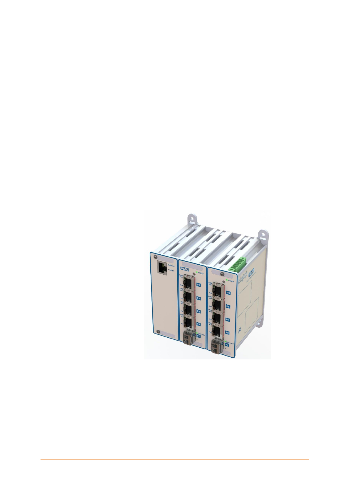
1.2 AMG9IM2-8G-2S
21hp : 8x RJ45 GbE + 2x SFP GbE
Figure 1-1 : 9IM2-8G-2S
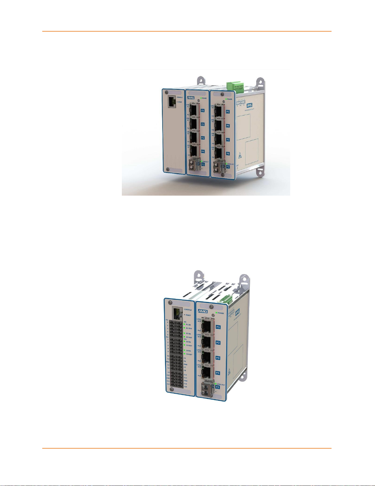
1.3 AMG91IM2-4FH-1S-4S16C
14hp : 4x FE (4 PoE+) + 4x serial + 16x contact closures + 1x SFP
GbE/FE
Figure 1-2 : 91IM2-4FH-1S-4S16C
9IM2X/9HM2X USER MANUAL 21
AMG SYSTEMS LTD.
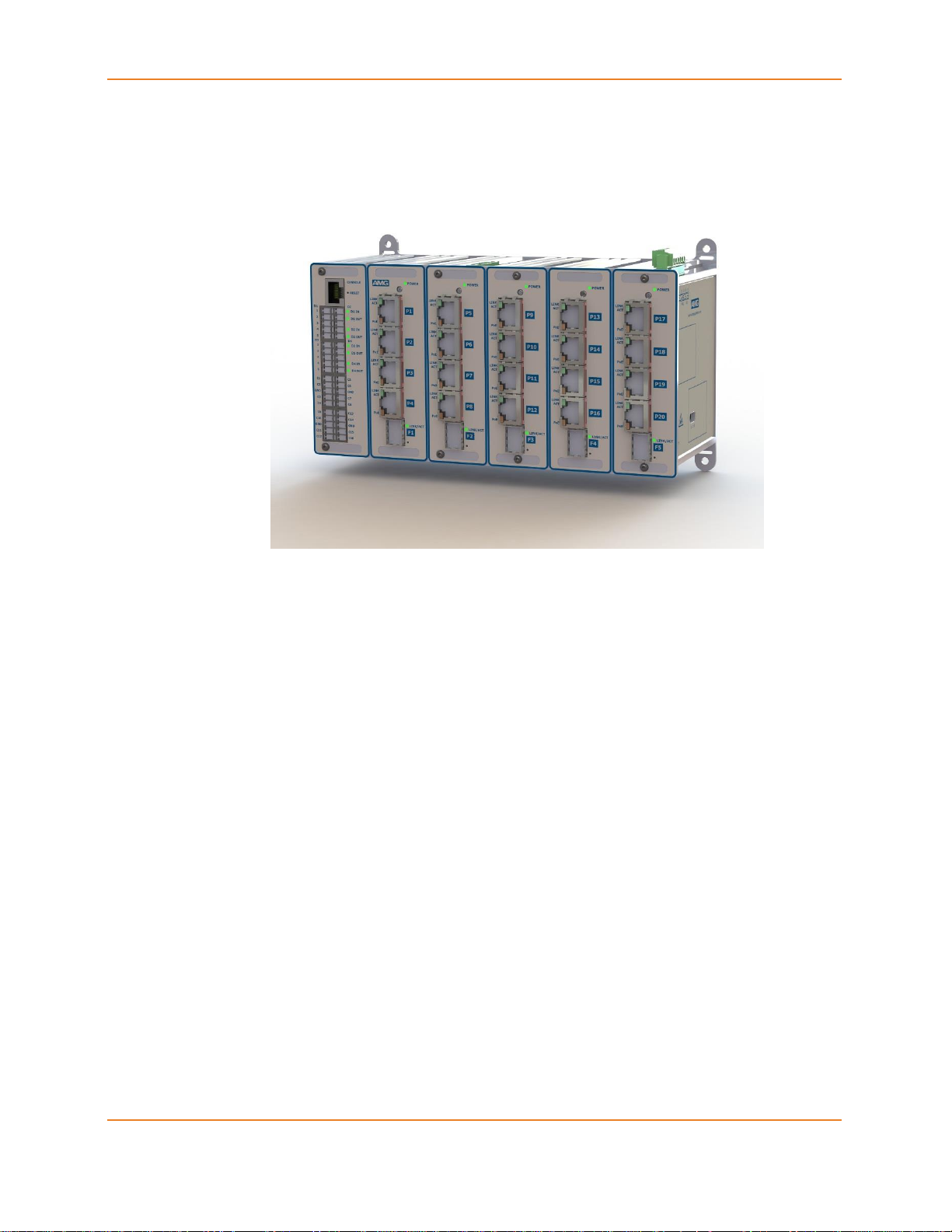
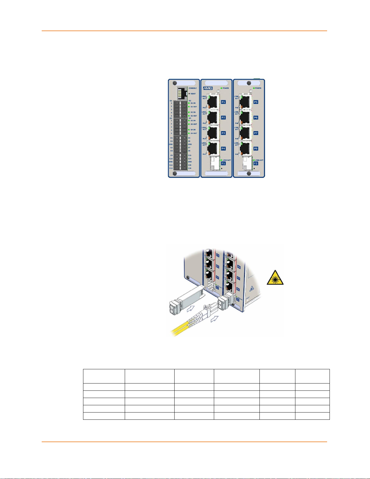
1.4 AMG91IM2-20GH-5S-4S16C-P240
42hp : 20x GbE + 4x serial + 16x contact closures + 5x SFP GbE/FE
Figure 1-3 : 91IM2-20GH-5S-4S16C-P240
USER MANUAL AMG 9IM2X/9HM2X 22

CHAPTER 2 : HARDWARE DESCRIPTION
Chapter
2
Hardware Description
This section describes AMG 9IM2x/9HM2x hardware. It describes how the
different ports, LEDs and connectors are to be used.
AMG 9IM2x/9HM2x has ports for connectivity to different devices. These
ports can be categorized into 3 categories
Console port – RJ45 serial RS-232 data for access to CLI (Command Line)
interface.
Ethernet ports – used for Ethernet connectivity. These ports can be copper
ports or Transceiver ports. Copper ports can operate at speeds of
10/100/1000 Mbps. Transceiver ports can accommodate optical connectivity
through Fibre transceivers as well as copper connectivity through copper
transceivers.
I/O Ports – This product series has support for built-in I/O ports in order to
accommodate serial data ports, alarm contacts, audio devices and video
encoder ports without requirement for any additional hardware.
AMG 9IM2x/9HM2x has LEDs on the front panel to indicate status and
activities of different ports in the system.
Use the following hyperlinks to view the various hardware features:
Management Console Connections
Ethernet Connections
I/O Connections
Pin Layout of data connectors
Power Connector
Power over Ethernet
Ethernet Port LEDs
I/O Port LEDs
9IM2X/9HM2X USER MANUAL 23
AMG SYSTEMS LTD.
RJ45 Cable
Colour
T568B
AMG
RJ45
Pin No.
RJ45
RS232
Signal
RJ45
DCE Wire
Colour
DB9
RS232
Pin No.
PC
DTE
RS-232
Signal
White/Orange
1
n/c
Blue
1
DCD
Orange
2
Tx-OUT
Orange
2
Rx-IN
White/Green
3
Rx-IN
Black
3
Tx-OUT
Blue
4
n/c
Red
4
DTR
White/Blue
5
GND
Green
5
GND
Green
6
n/c
Yellow
6
DSR
White/Brown
7
n/c
Brown
7
RTS
Brown
8
n/c
White
8
CTS
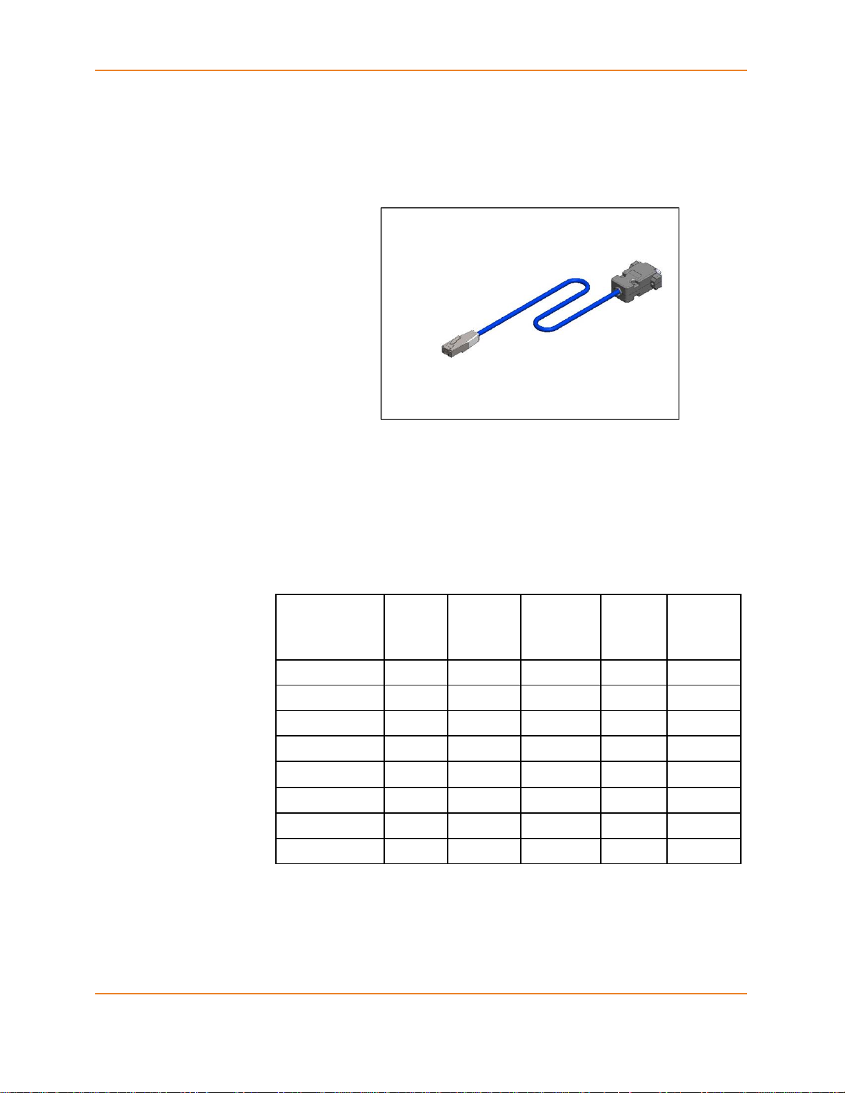
2.1 Management Console
Console port – RJ45 serial RS-232 data for access to CLI (Command Line)
interface. Management of M-SES from PC using serial terminal application
such as PuTTY, Hyperterminal etc. is possible using RJ45 to DB9 Adaptor /
Cable provided.
Figure 2-1 : Console Adaptor / Cable
Console connections are provide using supplied AMG RJ45 to DB9 Adaptor.
This provides a direct connection to a PC’s DB9 serial port using a “straightthough” Ethernet patch cable.
Note. only DB9 pins 2,3,5 are actually used – but all wires are connected in
the adaptor as shown in the following table:
Table 2-1 : Console Port Connections
USER MANUAL AMG 9IM2X/9HM2X 24
CHAPTER 2 : HARDWARE DESCRIPTION
AMG Part
Numbers
Ports
Supported
Fibre
Type
Wavelength
Tx (nm)
Speed
(Mbps)
Max
distance
S18074
F1-F6, FA-FC
dual fibre
1310
100
20km
S18170
F1-F6, FA-FC
dual fibre
1310
100
40km
S18056
F1-F6, FA-FC
dual fibre
1310
1000
20km
S18057
F1-F6, FA-FC
dual fibre
1550
1000
40km
S18054/55
F1-F6, FA-FC
single fibre
1310/1550
1000
40km
2.2 Ethernet Connections
Ports P1 to P24 have RJ45 connectors providing 10/100/1000Mbps.
Figure 2-2 : RJ45 Ethernet Ports
Ports F1 to F6 and FA to FC are SFP transceiver ports for use with fibre or
copper SFPs. For further details see tables below.
Figure 2-3 : SFP Transceiver Ports
Singlemode Fibre
Table 2-2 : Singlemode Fibre SFPs
9IM2X/9HM2X USER MANUAL 25
AMG SYSTEMS LTD.
AMG Part
Numbers
Ports
Supported
Fibre
Type
Wavelength
Tx (nm)
Speed
(Mbps)
Max
distance
S18082
F1-F6, FA-FC
dual fibre
1310
100
2km
S18095/96
F1-F6, FA-FC
single fibre
1550/1310
100
2km
S18200/201
F1-F6, FA-FC
single fibre
1550/1310
1000
500m
AMG Part
Numbers
Ports
Supported
Connector
Type
Speed
(Mbps)
Max
distance
S24010
F1-F6, FA-FC
RJ45
10/100/1000
100m
S24010
F1-F6, FA-FC
RJ45
1000
100m
Multi-Mode Fibre
Table 2-3 : Multi-mode Fibre SFPs
Copper
Table 2-4 : Copper SFPs
Note: for unsupported transceivers AMG 9IM2x/9HM2x Management
Interface gives the provision to configure the speed manually.
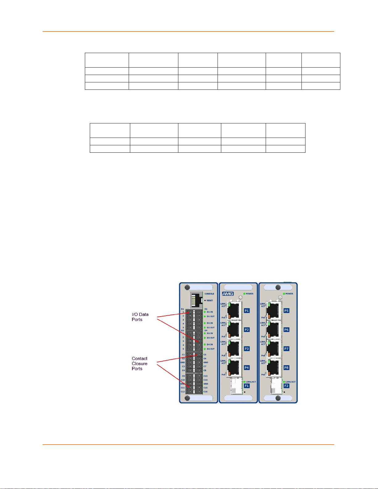
2.3 I/O Connections
For low speed serial data ports (RS-232/RS-485/RS-422) and other I/O, the
device provides up to 8x 5-way connectors depending on the model variant.
Each connector is a Phoenix style connector providing a total of 4x BiDirectional low speed data ports D1-D4 and 16x configurable contact closure
ports C1-C16.
Figure 2-4 : I/O Connections
USER MANUAL AMG 9IM2X/9HM2X 26

CHAPTER 2 : HARDWARE DESCRIPTION
Data
Port
Pin
No.
RS-422
RS-485
RS-232
D1 1 D1 Data OUT- (B)
D1 Data IN/OUT- (B)
D1 Data OUT (Tx)
D1 2 D1 Data OUT+ (A)
D1 Data IN/OUT+ (A)
D1 3 GND
GND
GND
D1 4 D1 Data IN- (B)
D1 5 D1 Data IN+ (A)
D1 Data IN (Rx)
Data
Port
Pin
No.
RS-422
RS-485
RS-232
D2 1 D2 Data OUT- (B)
D2 Data IN/OUT- (B)
D2 Data OUT (Tx)
D2 2 D2 Data OUT+ (A)
D2 Data IN/OUT+ (A)
D2 3 GND
GND
GND
D2 4 D2 Data IN- (B)
D2 5 D2 Data IN+ (A)
D2 Data IN (Rx)
Data
Port
Pin
No.
RS-422
RS-485
RS-232
D3 1 D3 Data OUT- (B)
D3 Data IN/OUT- (B)
D3 Data OUT (Tx)
D3 2 D3 Data OUT+ (A)
D3 Data IN/OUT+ (A)
D3 3 GND
GND
GND
D3 4 D3 Data IN- (B)
D3 5 D3 Data IN+ (A)
D3 Data IN (Rx)
Data
Port
Pin
No.
RS-422
RS-485
RS-232
D4 1 D4 Data OUT- (B)
D4 Data IN/OUT- (B)
D4 Data OUT (Tx)
D4 2 D4 Data OUT+ (A)
D4 Data IN/OUT+ (A)
D4 3 GND
GND
GND
D4 4 D4 Data IN- (B)
D4 5 D4 Data IN+ (A)
D4 Data IN (Rx)
2.4 Pin Layout of I/O Connectors
Serial Data Ports D1-D4
Note: (A) or (B) in brackets in the tables below refer to RS-485 / RS-422 data specification
Table 2-5 : Serial Data I/O Connections
9IM2X/9HM2X USER MANUAL 27

AMG SYSTEMS LTD.
Pin
name
Pin
name
C1
C5
C2
C6
GND
GND
C3
C7
C4
C8
C9
C13
C10
C14
GND
GND
C11
C15
C12
C16
Contact Closure ports C1-C16
The AMG 9IM2x/9HM2x provides 16 contact closure inputs / outputs. Each contact closure may be
configured as either an intput (IN) or an output (OUT).
Each CC IN is a digital ON/OFF input typically used to detect contact closure status. The detection circuit
is via an internal 8.2kΩ series resistor with a 47kΩ pull-up resistor to the internal +3V3 supply.
LOW level : input voltage < 0.5V or a low impedance (0Ω to 1kΩ) short circuit to GND
HIGH level : input voltage > +3V3 to +24Vdc or an open circuit.
Each CC OUT is a digital ON/OFF output (current sink) typically used to convey contact closure status.
Each output circuit is an open drain power MOSFET with series 4.7Ω resistor and has a maximum rated
continuous load current of 250mA, and maximum input voltage of +24Vdc.
Table 2-6 : Contact Closure I/O Connections
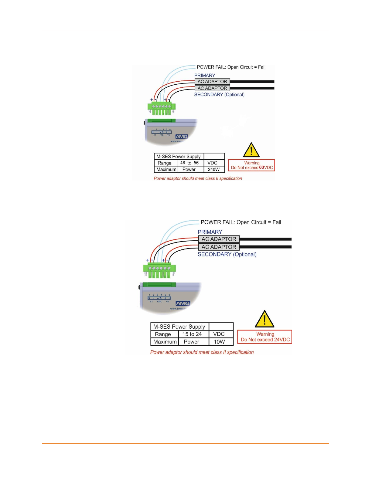
2.5 Power Connector
Power Connectors used in AMG 9IM2x/9HM2x depends on the device
variant and Power over Ethernet (POE) support on the device.
+48V DC to +56V DC – For POE variant.
+12V DC to +24V DC – For non-POE variant.
Please note : Total system load should not exceed 240W.
USER MANUAL AMG 9IM2X/9HM2X 28
CHAPTER 2 : HARDWARE DESCRIPTION
Figure 2-5 : PoE Power Connections
Figure 2-6 : Non PoE Power Connections
2.6 Power over Ethernet
Power over Ethernet (PoE) is a provision to power over Ethernet cables. So,
an Ethernet cables carries both data and current together to operate devices
like IP cameras. This is very helpful to install devices in remote places such
9IM2X/9HM2X USER MANUAL 29
AMG SYSTEMS LTD.
Parameter
PoE
PoE+
PoE-U
PoH
Input Voltage
48-50V
56-60V
56-60V
56-60V
Output Power
15W
25W
60W
90W
Output Voltage
44-48V
52-56V
52-56V
52-56V
as ceilings, where it is hard to find power outlets. Only smaller devices can
be powered using the PoE, as it carries limited power over the Ethernet.
1. The original IEEE 802.3af-2003 PoE standard provides up to 15.4 W of
DC power (minimum 44 V DC and 350 mA) to each device. Only 12.95 W is
assured to be available at the powered device as some power is dissipated
in the cable.
2. The updated IEEE 802.3at-2009 PoE standard also known as PoE+ or
PoE plus, provides up to 25.5 W of power per port/device.
3. PoE-U / PoH non-ratified standards provide up to 60W / 90W of power per
port/device.
Here are POE specifications of AMG 9IM2x/9HM2x per port :
Table 2-7 : POE Specifications
Please note : Total system load should not exceed 240W.
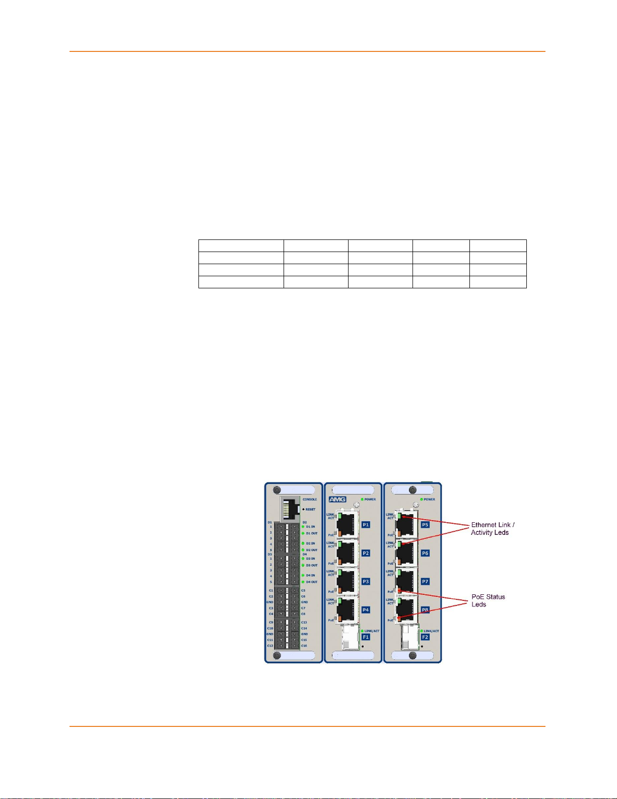
2.7 Ethernet Port LEDs
Each non-transceiver Ethernet port has two LEDs - Link/Activity and PoE
power output status. These are are situated on the left side of each RJ45
port-connector as depicted below:
Figure 2-7 : Ethernet Port LEDs
USER MANUAL AMG 9IM2X/9HM2X 30

CHAPTER 2 : HARDWARE DESCRIPTION
Each SFP Ethernet transceiver port has a single LED - Link/Activity. This is
situated on the right side of each SFP port-connector as depicted below:
Figure 2-8 : SFP Transceiver Port LEDs
2.8 I/O Port LEDs
I/O port LEDs may be present on the front panel depending on the variant of
the AMG 9IM2x/9HM2x.
Models which support serial data ports, contact closure signals /alarm have
LED indicators to display the status on the input/output. These LEDs are
depicted as follows:
Figure 2-9 : I/O Port LEDs
9IM2X/9HM2X USER MANUAL 31

AMG SYSTEMS LTD.
Chapter
3
HS-IO Hardware Description
This section describes HS-IO hardware. It describes how different ports,
LEDs and connectors are to be used.
In order to provide very low latency (< 5 milliseconds) end to end
transmission of serial data over IP, the AMG M-SES can be equipped with a
“high-speed” / low latency serial data expander module which provides 2 or 4
bi-directional serial data ports which are individually configurable for RS-232
/ RS-485 or RS-422 serial data:
AMG9HMX-2S : 2 serial data ports.
AMG9HMX-4S : 4 serial data ports.
Future options will also provide contact closure variants as follows:
AMG9HMX-2S8C : 2 serial data ports, 8 Contact Closures.
AMG9HMX-4S4C : 4 serial data ports, 4 Contact Closures.
Use the following hyperlinks to view the various hardware features:
HS-IO Connections
HS-IO Front panel LEDs
HS-IO Data Channel Interface
HS-IO Contact Closure Interface
USER MANUAL AMG 9IM2X/9HM2X 32

CHAPTER 3 : HS-IO HARDWARE DESCRIPTION
3.1 HS-IO Connections
Note : The Expander Module is connected to the M-SES unit by an external Ethernet
(100Mbps) RJ45 to RJ45 Patch cable.
Power Connection
Connector Type…………………………Removable 2-pin, 3.81mm, Screw Terminal
Connector Partno……………………….Phoenix 1803578
Supply Voltage………………………….+12 to +15 Volts DC
Maximum Power………………………..1 Watt
Data and Alarm Channel Connections
No. of Data Channels…………………..2 or 4
No. of Alarms…………………………....4 or 8
Connectors……………………………….Removable 5-pin, 3.5mm, Spring Terminal
Connector Partnos………………………Phoenix 1952296
Data Interfaces…………………………..RS-232 / 422 / 485. Selected by external slide switches D1-D2
RS-232 – Switch Position - Top
RS-422 – Switch Position - Middle
RS-485 – Switch Position - Bottom
Internal 120Ω termination resistors may be applied to RS-422 or RS-485 inputs as required by internal DIL
switches (P0-P3) inside the enclosure. The switches may be accessed by removing the 2 fixing screws in
the rear panel and sliding the PCB out of the enclosure.
Alarm inputs……………………………..Input is via a series 10k resister with 47kΩ pull-up to +3V3.
Alarm outputs……………………………Output is NPN open collector, maximum load 500mA @ 24Vdc
Ethernet Connection
Ethernet Data Connector…………........RJ45
Interface………………………………….Auto-negotiation up to 100BASE-TX full duplex
Ethernet Data Rate……………………..100Mb/s.
9IM2X/9HM2X USER MANUAL 33

AMG SYSTEMS LTD.
3.2 HS-IO Front panel LEDs
Power LED
Power……………………………………Green - Unit powered.
Low Speed Data LEDs
Data Present IN (RS-485 or RS-422)…..Red - data present on IN+, IN Off - data not present on IN+, IN-
Data Present IN (RS-232)……………..Green - logic zero (+V) present on input IN+
Red - logic transitions present on IN+
Off - logic one (-V) present on input IN+
IN corresponds to the data signals being transmitted onto network
Data Present OUT (RS-485 or RS-422)..Red - data present on OUT+, OUT-
Off - tristate / data off on OUT+, OUTData Present OUT (RS-232)…………..Green - logic zero (+V) present on OUT+
Red - logic transitions present on OUT+
Off - logic one (-V) present on OUT+
OUT corresponds to the data signals being received from network
Contact Closure LEDs
Channels 1-8
ALARM IN………………………………Green - Contacts closed.
Off - Contacts open.
ALARM OUT…………………………...Green - Contacts closed.
Off - Contacts open.
Ethernet Data LEDs
Link not Present……………………….Yellow - Link not present
Off - Link is present
Link Integrity……………………………Green - Link integrity is good, Idle state
Green Blink - Data transfer
Off - Link not present
Data Channel and Contact Closure Configuration
The 4 physical serial data interfaces RS-485, RS-422 or RS-232 are
individually selectable by the user with the slide switches mounted on the
rear panel.
There are also 2 or 4 bi-directional Contact Closure inputs/outputs. Each
contact closure can receive an on/off signal and is typically used to convey
contact closure status.
USER MANUAL AMG 9IM2X/9HM2X 34

CHAPTER 3 : HS-IO HARDWARE DESCRIPTION
Connector
Pin No.
Data Channel
RS-485
[switch bottom]
RS-422
[switch middle]
RS-232
[switch top]
1
IN/OUT - (B)
OUT - (B)
OUT
2
IN/OUT + (A)
OUT + (A)
3
GND
GND
GND
4 IN - (B)
5 IN + (A)
IN
3.3 HS-IO Data Channel Interface
Each low speed data channel provides an RS-232, RS-422 (full duplex, four
wire) or RS-485 (half duplex, two wire) interface defined by the slide switch
mounted from the rear panel Every data channel as shipped from the factory
is set up for RS-485 operation unless otherwise requested.
The OUT+- data drivers for RS-485 and RS-422 modes will be in the OFF
(tristate condition) unless OUT data is being transmitted.
HS-IO Data Interface Connections
Table 3-1 : HS-IO HS-IO Serial Data Interface Connections
Note : (A) or (B) in brackets in the above table refers to RS-485 / RS-422
data specification.
HS-IO Data Channel Termination
The interface mode RS-232, RS-422 or RS-485 of each data port Data 1-4,
is selected with the corresponding external slide switch D1-D4. The actual
number of data channels provided on the unit depends upon the AMG
model.
Internal 120Ω termination resistors across IN+ and IN- inputs may also be
applied when in RS-422 or RS-485 mode using internal DIP switches P0-P3
on the main PCB inside the enclosure. P0-P3 may be accessed by removing
the 2 fixing screws in the rear panel and sliding the PCB out of the enclosure.
For clarity, in the 3 examples shown below all 4 data ports D1-D4 are
terminated the same, but each data channel may be configured & terminated
independently as required. The 3 examples shown are RS-232 (no
termination), RS-422 (120Ω) or RS-485 (120Ω).
9IM2X/9HM2X USER MANUAL 35

AMG SYSTEMS LTD.
Figure 3-1 : HS-IO Serial Data Interface Connections
3.4 HS-IO Contact Closure Interface
High Speed Serial Expander also provides 4 or 8 bi-directional contact
closure inputs/outputs.
Each CC IN input is via an internal 10kΩ series resistor with a 47kΩ pull-up
resistor to the internal +3V3 supply.
Each CC OUT output is an NPN open collector circuit with a maximum rated
continuous load of 500mA / 24Vdc.
USER MANUAL AMG 9IM2X/9HM2X 36

CHAPTER 3 : HS-IO HARDWARE DESCRIPTION
Connector
Pin No.
Contact Closures
CC IN
1-4, 5-8
CC OUT
1-4 , 5-8
1
CC 1/5 IN
CC 1/5 OUT
2
CC 2/6 IN
CC 2/6 OUT
3
GND
GND
4
CC 3/7 IN
CC 3/7 OUT
5
CC 4/8 IN
CC 4/8 OUT
HS-IO Contact Closure Connections
Table 3-2 : HS-IO HS-IO Contact Closure Connections
9IM2X/9HM2X USER MANUAL 37

AMG SYSTEMS LTD.
Chapter
4
Installation Guide
This section describes how to install the AMG 9IM2x/9HM2x Multi-Service
Ethernet Switch.
Use the following hyperlinks to view the various installation features:
Unpacking the Switch
Installing Pre-requisites
Mounting the Switch
Power Connections
Connecting to Network
Connecting to Management Console
USER MANUAL AMG 9IM2X/9HM2X 38

CHAPTER 4 : INSTALLATION GUIDE
4.1 Unpacking the Switch
Before unpacking the switch, inspect the package and immediately report
any evidence of damage.
i. Place the box on a clean flat surface.
ii. Open the box or remove the box top.
iii. Carefully remove the switch from the box and place it on a
secure and clean surface.
iv. Remove all packing material.
v. Inspect the switch and accessories for damage. Report any
damage immediately.
While unpacking the switch, ensure that the following items are included:
Ethernet Switch
AC power Adaptor & IEC Mains cable
RS-232 console cable / RJ45 Adaptor
Documentation CD
Product Quick Start Guide
4.2 Installing Pre-requisites
AMG 9IM2x/9HM2x series devices can be mounted in a standard equipment
rack or enclosure, using industry standard DIN rail. Before installing the unit,
verify that the chosen location for installation meets the following site
requirements:
Power: the unit is installed near an easily accessible 100-240 VAC, 50-60
Hz outlet.
Clearance: there is adequate frontal clearance for operator access. Allow
clearance for cabling, power connections, and ventilation.
Cabling: the cabling is routed to avoid sources of electrical noise such as
radio transmitters, broadcast amplifiers, power lines, and fluorescent lighting
fixtures.
Ambient Requirements: the ambient unit operating temperature range is 20 to 74ºC at a relative humidity of 0% to 95%, non-condensing.
4.3 Mounting the Switch
Mounting the unit is shown as follows:
9IM2X/9HM2X USER MANUAL 39

AMG SYSTEMS LTD.
Figure 4-1 : Mounting the unit - DIN Rail
Figure 4-2 : Mounting the unit - Surface
4.4 Power Connections
Plug the supplied IEC-8 mains power cable to the AC adaptor mains input
connector.
Plug the AC adaptor DC output connector into the DC power input connector
on the AMG 9IM2x/9HM2x switch top panel.
USER MANUAL AMG 9IM2X/9HM2X 40

CHAPTER 4 : INSTALLATION GUIDE
Turn the incoming mains supply on and confirm that the switch is receiving
power and operating correctly by examining the LEDs on the front panel.
Figure 4-3 : DC Power Connection
4.5 Connecting to Network
Configuration, Management and maintenance of AMG 9IM2x/9HM2x switch
is done through web management interface. In order to operate switch, it
should be have IP for connectivity. Switch can get can IP either through
DHCP or through static IP address assignment.
If the switch is assigned a non-default static IP address, it is labelled on the
side panel of the switch. Otherwise, switch operates at a static IP address –
192.168.1.101
9IM2X/9HM2X USER MANUAL 41

AMG SYSTEMS LTD.
Connecting the switch with default IP address can be depicted as follows:
Figure 4-4 : Network Connections
4.6 Connecting to RS-232 Management Console
If access to AMG 9IM2x/9HM2x switch via CLI (Command Line) interface is
required, connect the Console cable / adaptor RJ45 into the console port
and connect the DB9 serial RS-232 data port to a PC or similar.
Figure 4-5 : Console Connections
Login to the AMG 9IM2x/9HM2x switch via CLI (Command Line) interface
Connect using a terminal application such as PuTTY or RealTerm : Serial
COM port, Speed 115200
USER MANUAL AMG 9IM2X/9HM2X 42

CHAPTER 4 : INSTALLATION GUIDE
Default logon "Admin" Password "Admin"
Figure 4-6 : Login through CLI
9IM2X/9HM2X USER MANUAL 43

AMG SYSTEMS LTD.
Chapter
5
Web Interface Conventions
This section describes how the Web Interface is used to view, configure and
control the AMG 9IM2x/9HM2x Multi-Service Ethernet switch.
Use the following hyperlinks to view the various Web Interface features:
WEB interface
Internet Explorer Settings
Document Conventions
USER MANUAL AMG 9IM2X/9HM2X 44

CHAPTER 5 : WEB INTERFACE CONVENTIONS
5.1 WEB interface
AMG 9IM2x/9HM2x WEB interface is composed of different screen
elements which are used to get input from user and/or to display output.
These screen elements are Text Fields, Number Fields, Option Buttons,
Check Boxes, Combo Boxes, Buttons, Text Areas and Lists.
Web User Interface facilitates new and inexperienced users to create the
basic routing and security functions, quickly and effectively.
Note : some advanced configuration options can be set only through the CLI.
A field entry with a * symbol displayed in a Web screen, denotes that it is a
mandatory field.
The following sample screens depict the AMG 9IM2x/9HM2x Web interface
with the standard screen elements named, as it is used in this document.
Figure 5-1 : Web GUI screen sample 1
9IM2X/9HM2X USER MANUAL 45

AMG SYSTEMS LTD.
Figure 5-2 : Web GUI screen sample 2
USER MANUAL AMG 9IM2X/9HM2X 46

CHAPTER 5 : WEB INTERFACE CONVENTIONS
5.2 Internet Explorer Settings
For Product screens viewed in Internet Explorer, ensure the browser setting
is as given below;
Click Tools from the Menu bar of the browser.
Figure 5-3 : Browser General Settings Tab
Under General tab, click on Browsing History Settings.
Figure 5-4 : Browser History Settings
Select “Every time I visit the webpage” option as shown.
Click OK.
9IM2X/9HM2X USER MANUAL 47

AMG SYSTEMS LTD.
Convention
Usage
Example
Arial Bold 10
Navigation path to each screen. Includes
tab name also.
System > IP Authorized Manager >
IP Authorized Manager.
Any references to screen elements like
action Buttons, option Buttons, check
boxes, screens names.
There are two options to save the
configuration data namely, Flash
Save and Remote Save.
Arial 10 Italics
User Inputs to Fields
Specify the name of the configuration
file available in the remote system.
The default file name is AMG.conf.
Denotes any additional information on an
associated topic.
All the configurations are
active only when the
SNTP module is enabled.
5.3 Document Conventions
Definitions and AcronymsError! Reference source not found. lists the
erms and typographical conventions used in this document.
Table 5-1 : Conventions Used in this Document
USER MANUAL AMG 9IM2X/9HM2X 48

6 : LOGGING INTO AMG 9IM2X/9HM2X
Chapter
6
Logging into AMG 9IM2x/9HM2x
The AMG 9IM2x/9HM2x WEB User interface allows the user to control
various parameters at the System Level and Protocol level.
The basic configurations such as provisioning of default IP address, VLAN
configuration etc. may also be performed through the console CLI
(Command Line Interface) provided by AMG 9IM2x/9HM2x .
Use the following hyperlinks to view the various Logging into the switch
features :
Login
Home Screen
49

AMG SYSTEMS LTD.
Screen Objective
This screen allows the user access AMG 9IM2x/9HM2x through WEB User
Interface
Fields
UserName - Enter the username.The default username is Admin.
Password - Enter the password. The default password is Admin.
This user name and password are set by default in the Switch. The
Command Line Interface can be used to create new users, delete
existing users and modify own password or the password of other
existing users. Refer the CLI user manual for details.
6.1 Login
Launch a web browser compatible with AMG 9IM2x/9HM2x on your PC.
Enter the Switch IP address in the Address bar of the web screen. For
example, if the IP address of the Switch interface is 192.168.1.101, then
enter http://192.168.1.101 in the address bar of the Web browser to access
the Switch
AMG 9IM2x/9HM2x is compatible with Internet Explorer 11.0, Mozilla
Firefox 40 and above
The screenshots depicted in this document are configured with Firefox.
Figure 6-1 : Login Screen
USER MANUAL AMG 9IM2X/9HM2X 50

CHAPTER 6 : LOGGING INTO AMG 9IM2X/9HM2X
The maximum login attempts with wrong password is by default set
as 3. This can be configured through CLI. The maximum login
attempts value ranges from 1 to 10.
Buttons
Login - To login to AMG 9IM2x/9HM2x and view the AMG 9IM2x/9HM2x
Home screen.
Screen Objective
This screen provides the user basic information about AMG 9IM2x/9HM2x and
also provides links to configure system and protocol parameters.
The Switch name shown on this screen and some other screens is
set by the user on System Information Page. In the screenshot
above it is "Test Lab 28"
Navigation
On successful Login from the Login screen.
Links
Left Navigation Pane - Links to Management screens to access system
and protocol configuration screens. The links are categorized based on the
protocol feature and functionality:
6.2 Home Screen
Figure 6-2 : Home Screen
51

AMG SYSTEMS LTD.
Right Top corner Links - The following standard set of links is displayed
on the right hand side top corner of the all the Web screens:
Support: To get high-quality and responsive technical support.
Help: To open the help screen.
Help text is currently not available.
About: To get additional information about Web management.
Log Out: To Log out the Web session through which the user is
connected.
USER MANUAL AMG 9IM2X/9HM2X 52

7 : LEFT NAVIGATION PANE
Chapter
7
Left Navigation Pane
This chapter describes the organization of the sub-menus and features
available from the Left Navigation Pane.
The System and Management parameters are configured through the
screens displayed by the following items in the Left Navigation Pane :
System
Layer2 Management
IP Management
Multicast
I/O Management
Statistics
53

AMG SYSTEMS LTD.
7.1 System
Figure 7-1 : System Information Home Page
This link has sub-links in the left navigation pane for all system specific
configurations and system specific modules. You can perform system
specific configurations through the screens displayed by these links.
The System link on the left pane provides access to the following links.
These are included as individual chapters in the user manual.
System Information
User Management
Save and Restore
Software Upgrade
Reboot
SNTP
HTTP
USER MANUAL AMG 9IM2X/9HM2X 54

CHAPTER 7 : LEFT NAVIGATION PANE
SNMP
7.2 Layer2 Management
Figure 7-2 : Layer2 Management Home Page
This link has sub-links for all Layer2 related features and modules. You can
perform Layer2 configurations through the screens displayed by these links.
The Layer2 Management link on the left pane provides access to the
following links. These are included as individual chapters in the user manual.
Port Manager
VLAN
Address Tables
MSTP
RSTP
LLDP
55

AMG SYSTEMS LTD.
802.1x
7.3 IP Management
Figure 7-3 : IP Management Home Page
This link has sub-links for all IP related features and modules. You can
perform IP configurations through the screens displayed by these links.
The IP Management link on the left pane provides access to the following
links.
IP
DHCP Server
USER MANUAL AMG 9IM2X/9HM2X 56

CHAPTER 7 : LEFT NAVIGATION PANE
7.4 Multicast
Figure 7-4 : Multicast Home Page
This link has sub-links for multicast protocols, which are involved in
transmitting a message to a set of selected multiple recipients.
The Multicast link on the left pane provides access to the following links.
These are included as individual chapters in the user manual.
IGMP Snooping
TAC
57

AMG SYSTEMS LTD.
7.5 I/O Management
Figure 7-5 : I/O Management Home Page
This link has sub-links in the left navigation pane for all I/O specific
configurations and system specific modules. You can perform I/O specific
configurations through the screens displayed by these links.
The I/O link on the left pane provides access to the following links. These are
included as individual chapters in the user manual.
Serial
Contact Closures
HS-IO
USER MANUAL AMG 9IM2X/9HM2X 58

CHAPTER 7 : LEFT NAVIGATION PANE
7.6 Statistics
Figure 7-6 : Statistics Home Page
This link has sub-links for statistics of several modules and features. You can
view statistics details.
The Statistics link on the left pane provides access to the following links.
These are included as individual chapters in the user manual. Interface
Interface
MSTP
RSTP
LLDP
802.1x
Radius
IGMP Snooping
IP
SNMP
59

AMG SYSTEMS LTD.
Chapter
8
System Information
To access System Information screens, click System > System
Information.
USER MANUAL AMG 9IM2X/9HM2X 60

CHAPTER 8 : SYSTEM INFORMATION
Screen Objective
This screen allows the user to configure the system information
Navigation
System > System Information
Fields
Hardware Version - Displays the hardware version number of the
system.
Firmware Version - Displays the firmware version number of the system.
Switch Name - Enter the name for identifying the device. This value
range is a string of size 15.
Part Number - Displays the AMG Part number.
System Contact - Enter the contact person details for this managed
node. This value range is a string of size 50. If the contact information is not
available, this value takes a zero-length string.
8.1 System Information
Figure 8-1 : System Information
61

AMG SYSTEMS LTD.
System Location - Enter the physical location of this node. This value
range is a string of size 50.. If the location is unknown, this value takes a
zero-length string.
Device Up Time - Displays the time from which the device is up. The
format is Days Hours, Minutes, Seconds Example: 0 Days 1 Hrs, 15 Mins,
27 Secs.
Switch Base MAC Address - Displays the device's unique physical
MAC Address in hexadecimal format i.e. 54:51:46:00:00:7b .
SNMP Engine ID - Displays the device's unique identifier in hexadecimal
format i.e. 80.00.08.1c.04.46.53.
System Time - Select the current date and time The format is Day Month
Date Year Hours Minutes Seconds Example: Fri May 07 2010 13: 40: 00.
This value range is a string of size 40.
Login Authentication Mode - Select the login authentication mode. The
list contains:
Local – Sets the authentication mode as Local. The user identification,
authentication, and authorization method is chosen by the local system
administration and does not necessarily comply with any other profiles.
Remote – Sets the authentication mode as Remote. Authentication is
done in the remote location through a RADIUS (Remote Authentication
Dial-In User Service) or TACACS server. RADIUS is a protocol that
enables remote access servers to communicate with a central server to
authenticate dial-in users and authorize their access to the requested
system or service. TACACS (Terminal Access Controller AccessControl System) is a remote authentication protocol that is used to
communicate with an authentication server commonly used in
networks.
Tacacs - Sets the authentication mode as TACACS. Authentication is
done through a TACACS+ server.
Configuration Save Status - Displays the configuration save status.
The default option is Not Initiated Once the configuration is done, the save
status will be displayed as any of the following:
Successful – System information is configured and saved
successfully.
Failure - System information configuration save failed.
Inprogress - System information configuration save is in-progress.
Not Initiated - System information configuration save is not initiated.
Remote Save Status - Displays the remote save status. The default
option is Not Initiated This status represents the status of save operation
to the remote location as any of the following:
Successful –Remote information is configured and saved successfully
Failure - Remote information configuration save failed.
In Progress - Remote information configuration save is in-progress.
USER MANUAL AMG 9IM2X/9HM2X 62

CHAPTER 8 : SYSTEM INFORMATION
Not Initiated - Remote information configuration save is not initiated.
Configuration Restore Status - Displays the configuration restoration
status. The default option is Not Initiated The already configured
parameter will be restored and the status will be displayed as any of the
following
Successful – Configuration is restored successfully.
Failure – Configuration restoration failed.
Inprogress – Configuration restoration is in-progress.
Not Initiated – Configuration restoration is not initiated.
Http Server Status - Displays the status of the HTTP server as either
enable or disable. The default option is Enable.
Http Port Number - Displays the port to be used by the host to configure
the router using the Web interface. This value ranges from 1 to 65535. The
default value is 80.
Once the port number is changed, the Http Server Status is
disabled and enabled. Open the HTTP session with IP address and
new port number. For example, enter as 12.0.0.1:100, where
12.0.0.1 represents the IP of the switch and 100 represents the port
number.
Telnet Status - Select to set the status of TELNET in the system. The
default option is Disable. The list contains the following;
Enable – Sets the Telnet status as enabled.
Disable – Sets the Telnet status as disabled.
Management Vlan ID - Select the Management VLAN to be used for an
IP connection to the switch from a workstation connected to a port in the
VLAN. The default value of 1 allows an IP connection to be established
through any port, but this may be changed if required to a different VLAN.
Ensure that the VLAN to be configured as the management
VLAN does exist, and the PVID of at least one port that is a port
of the VLAN is the same as the management VLAN ID.
Only one management VLAN can be active at a time.
When a new management VLAN is configured, connectivity (to
the GUI) through the existing management VLAN will be lost. The
management workstation should be reconnected to the port in the
new management VLAN.
Buttons
Apply - To modify attributes and save the changes
63

AMG SYSTEMS LTD.
Chapter
9
User Management
To access User Management screen, click System > User Management.
USER MANUAL AMG 9IM2X/9HM2X 64

CHAPTER 9 : USER MANAGEMENT
Screen Objective
This screen allows the user to add and remove authorised users who can then
access the switch.
In this software release it is not possible to give each user different
access privileges - every user will have full read/write access to all
features of the switch..
The default user name & password is Admin, Admin. However
once the default "Admin" password has been succesfully changed, it
is not possible to revert it back to "Admin" because there is a new
restriction on password characters used that "Admin" does not
meet. Yes - weird but true. We will change this in a future release.
This default password change can be reversed by using the rear
button reset - but this will also revert all switch parameters back to
their default values.
Navigation
System > User Management
Fields
User Name - Enter the required user name to add or change. This may be
either an pre-existing user or a new user.
Password - Enter the password required for the new or Existing user.
The Password must comprise of at least 5 ASCII characters.
9.1 User Management
Figure 9-1 : User Management
65

AMG SYSTEMS LTD.
The Password must include at least one numeric, one upper-case
character, one lower-case character and one special ASCII
character as defined as follows : !@#$%^&*()>`~_- +=|\/{}[]:;"'<,.?
Buttons
Add - Add the new user & password to the list or change the existing user's
password.
Delete - Add the new user & password to the list or change the existing user's
password.
USER MANUAL AMG 9IM2X/9HM2X 66

10 : SAVE AND RESTORE
Chapter
10
Save and Restore
The Save and Restore link allows the user to configure the current
configuration Save and Restore options for the switch:
To access Save and Restore screens, click System > Save and Restore.
The Save and Restore parameters are configured through the screens
displayed by the following tabs:
Save
Restore
File Download
By default the tab Save displays the Save Configuration screen.
67

AMG SYSTEMS LTD.
Screen Objective
This screen allows the user to save the current configuration of the AMG
9IM2x/9HM2x Switch in a file. When save operation is initiated, all
configurations made through CLI, SNMP or WEB interfaces are saved in a file
(default name is amg_mses.conf).
There are two options to save the configuration data namely, Flash Save and
Remote Save. A Flash Save Configures that the configurations need to be
saved in Flash whereas a Remote Save specifies that the configurations need
to be saved to a remote system.
Navigation
System > Save and Restore > Save
Fields
Save option - Click one of the option buttons to specify the save option to
be used for the Switch. The options are:
Flash Save – Saves the configurations in the specified file name of
Flash
Remote Save – Saves the configurations in the remote system which is
specified by Address Type and IP address
Transfer Mode - Select the transfer mechanism to save the Switch
configurations in the remote system. The remote host machine should have
10.1 Save Configuration
Figure 10-1 : Save configuration
USER MANUAL AMG 9IM2X/9HM2X 68

CHAPTER 10 : SAVE AND RESTORE
a TFTP / SFTP capable Server running for this operation to be successful.
The default option is TFTP. The list contains:
TFTP – Saves the Switch configurations to the remote system through
TFTP (Trivial File Transfer Protocol) mode.
SFTP – Saves the Switch configurations to the remote system through
SFTP (SSH File Transfer Protocol) mode.
This field is configurable only if the Save Option is set as Remote
Save.
Address Type - Select the IP Address type of the remote system in which
the Switch configurations are to be saved. The default option is IPv4. The
list contains:
IPv4 – Sets the Address type as IPv4.
IPv6 – Sets the Address type as IPv6.
This field is configurable only if the Save Option is set as Remote
Save.
IP Address - Enter the IP Address of the remote system in which the
Switch configurations are to be saved.
This field is configurable only if the Save Option is set as Remote
Save.
SFTP User Name - Enter the user name required for saving the Switch
configurations to the remote system in SFTP mode. This field is a string of
maximum size 20
This field is configurable only if the Save Option is set as Remote
Save and the Transfer Mode is set as SFTP.
SFTP Password - Enter the password required for saving the Switch
configurations on to the remote system in SFTP mode. This field is a string
of maximum size 20. The specified SFTP username / password should have
been configured in the SFTP server running the remote station, for the
remote save operation through SFTP to be successful.
This field is configurable only if the Save Option is set as Remote
Save and the Transfer Mode is set as SFTP.
File Name - Displays the name of the file in which the Switch
configurations are to be saved. The default file name where the Switch
configurations are saved is amg_mses.conf. All configurations are saved in
a single configuration file only.
This file name is used for saving the Switch configuration,
irrespective of the configuration Save Option which can be Flash or
Remote Save.
Buttons
Apply - To modify attributes and save the changes.
Reset - To reset to default value for respective fields and discard all user
inputs.
69

AMG SYSTEMS LTD.
Screen Objective
This screen allows the user to restore the previously saved configurations of the
Switch from the Startup Configuration File
Navigation
System > Save and Restore > Restore
Fields
Restore option - Click one of the option buttons to specify whether the
Switch configurations have to be restored. The list contains:
No Restore – Specifies that the switch configurations need not be
restored when the system is restarted
Flash Restore – Restores the configurations from the Startup
Configuration File in the Flash, when the system is restarted.
Buttons
Apply - To modify attributes and save the changes.
Reset - To reset to default value for respective fields and discard all user
inputs.
10.2 Restore Configuration
Figure 10-2 : Restore configuration
USER MANUAL AMG 9IM2X/9HM2X 70

CHAPTER 10 : SAVE AND RESTORE
Screen Objective
This screen allows the user to configure the file download details
Navigation
System > Save and restore > File Download
Fields
Transfer Protocol - Select the transfer mode for downloading file from
the remote system. The default option is TFTP. The list contains:
TFTP – Specifies that transfer mode for downloading file from the
remote system is TFTP (Trivial File Transfer Protocol)
SFTP – Specifies that transfer mode for downloading file from the
remote system is SFTP (SSH File Transfer Protocol)...
Address Type - Enter the Ip Address of machine to which the log file is to
be downloaded. The Options are
IPV4 - Sets the IP Address type as IPV4.
IPV6 - Sets the IP Address type as IPV6
Server IP Address - Enter the IP address of the machine from which the
file is to be downloaded.
SFTP User Name - Enter the user name required for downloading the file
in SFTP mode. This field is a string with the maximum size 20.
This field is disabled if the Transfer Protocol is selected as TFTP.
SFTP Password - Enter the password required for downloading the file in
SFTP mode. This field is a string with the maximum size 20.
This field is disabled if the Transfer Protocol is selected as TFTP.
10.3 File Download
Figure 10-3 : File Download
71

AMG SYSTEMS LTD.
File Name - Enter the name of the file to be downloaded from the remote
system.
Startup config - Select the function Startup configuration. A startup
configuration contains configuration information that the AMG 9IM2x/9HM2x
uses at reboot. This command retrieves a backup of the initial configuration
from flash or a remote location to use it for restoration.
Buttons
Apply - To modify attributes and save the changes.
Reset - To reset to default value for respective fields and discard all user
inputs.
USER MANUAL AMG 9IM2X/9HM2X 72

11 : SOFTWARE UPGRADE
Chapter
11
Software Upgrade
To access Software Upgrade screen, click System > Software Upgrade
73

AMG SYSTEMS LTD.
Screen Objective
This screen allows the user to perform a combined firmware download &
upgrade operation on a switch stack or standalone switch by downloading a
new upgrade pack (image file) from a local PC drive, USB key, or Ethernet
directory / location to the switch and overwriting and updating the existing
firmware.
The only web browser approved for the software upgrade
procedure at the current time is Microsoft Internet Explorer 11.
The software upgrade pack will be in compressed file format
(.tar.gz) and typically named "M.SES Release 2.x.x.tar.gz"
Navigation
System > Software Upgrade
Fields
Browse - Select the path / name of the upgrade pack to be downloaded.
Blank - The path / name of the selected upgrade pack.
Buttons
Submit - Confirm the selected upgrade pack and start the download & upgrade
process.
The user should wait for 1-2 minutes once the file download has
started. A warning message will flash alternately red & brown to
indicate this process is progressing. Do NOT re-boot or re-power
the switch at this time.
After the upgrade pack has been succesfully download, there may
be a small period of time 5-10 seconds whilst the image file is
unpacked and installed before a confirmation message appears. Do
NOT re-boot or re-power the switch at this time. WAIT for the
confirmation message to appear.
Reset - Clear the current selected upgrade pack.
11.1 Software Upgrade
Figure 11-1 : Software Upgrade
USER MANUAL AMG 9IM2X/9HM2X 74

CHAPTER 11 : SOFTWARE UPGRADE
Screen Objective
The following information screen informs the user that the upgrade pack
(image) download is in progress.
Screen Objective
The following screen informs the user that the upgrade pack (image) has
sucesfully been downloaded and the upgrade has been completed.
Figure 11-2 : Software Upgrade : File Upload in Progress
Figure 11-3 : Software Upgrade : File Upload Completed
The user should now re-boot or re-power the switch at this time.
75

AMG SYSTEMS LTD.
Chapter
12
Reboot
To access Reboot screen, click System > Reboot
USER MANUAL AMG 9IM2X/9HM2X 76

CHAPTER 12 : REBOOT
Screen Objective
This screen allows the user to restart the switch/ target...
The user should wait for 2 minutes before logging in after reboot.
All updates to nvram.file using the screen System > NVRAM
Settings > Factory Default Settings are effective only after reboot
Navigation
System > Reboot
Buttons
Reboot - To restart the switch.
12.1 Reboot
Figure 12-1 : Rebooting the System
77

AMG SYSTEMS LTD.
Chapter
13
SNTP
SNTP (Simple Network Time Protocol) is a simplified version of the NTP
protocol. The NTP protocol is meant for synchronizing the clocks of computer
systems over packet-switched, variable-latency data networks.
To access SNTP screens, click System > SNTP.
The File Transfer parameters are configured through the screens displayed
by the following tabs:
SNTP Global
SNTP Unicast Mode
By default the tab SNTP displays the SNTP Global Configuration screen.
USER MANUAL AMG 9IM2X/9HM2X 78

CHAPTER 13 : SNTP
Screen Objective
This screen allows the user to configure the details of SNTP scalars
To set the system time using SNTP, the Clock Time source should be
configured as NTP.
Navigation
System > SNTP > SNTP Global
Fields
Sntp Admin Status - Select the SNTP client module status. The default
option is Disabled. The list contains:
Enabled – Enables the SNTP client module. On enabling, the server
starts sending the request to the host for synchronization.
Disabled – Disables the SNTP client module.
All the configurations are active only when the SNTP module is
enabled.
Client Version - Select the SNTP client module version. The default option
is Version 4. The list contains:
Version 1 - Sets the SNTP client version as Version 1
Version 2 - Sets the SNTP client version as Version 2
Version 3 – Sets the SNTP client version as Version 3
Version 4 – Sets the SNTP client version as Version 4
13.1 SNTP Global Configuration
Figure 13-1 : SNTP Global Configuration
79

AMG SYSTEMS LTD.
All the SNTP requests are sent out with the current configured
version number. When required, the administrator can change the
current version number.
Addressing Mode - Displays the SNTP client addressing mode. The only
option is Unicast.
Unicast - SNTP client operates in a point-to-point fashion. A unicast
client sends a request to a designated server at its unicast address and
expects a reply from which it can determine the time and, optionally, the
round-trip delay and local clock offset relative to the server.
Sntp Client Port - Enter the SNTP client port number. This value ranges
from 1025 to 65535. The default value is 123.
Time Dislay Format - Select the time display format. The default option is
Hours. The list contains:
Hours – Sets the time display as 24 hours format.
Am/Pm – Sets the time display as 12 hours AM/PM format.
AuthKey Id - Enter the key identifier identifying the cryptographic key used
to generate the message-authentication code.
Auth Algorithm - Select the SNTP authentication algorithm. The default
authentication algorithm is None. The list contains:
None – The communication will be opened and no authorization will be
provided.
md5 - MD5 (Message Digest-5) verifies data integrity. MD5 is intended
for use with digital signature applications, which requires that large files
must be compressed by a secure method before being encrypted with a
secret key, under a public key cryptosystem.
AuthKey - Enter the authentication key that is used to implement NTP
authentication.
TimeZone - Enter the system time zone with respect to UTC. The format is
(+/-)HH:MM. Where:
+/- denotes the difference with the Greenwich Mean Time. + indicates
forward time zone and - indicates backward time zone.
HH denotes the hours. It is 24-hour format with value ranging from 00 to
23.
mm denotes the minutes. The value ranges from 00 to 59. For example,
the valid value is +05:30.
DST StartTime - Enter the DST (Daylight Saving Time) start time. The
format is weekofmonth-weekofday-month,HH:MM. Where:
Weekofmonth denotes the particular week. The valid values are First,
Second, Third, Fourth and Last.
weekofday denotes the day in the specified week. The valid values are
Sun, Mon, Tue, Wed, Thu, Fri and Sat.
USER MANUAL AMG 9IM2X/9HM2X 80

CHAPTER 13 : SNTP
month denotes the month for which the specified week and day are
applicable. The valid values are Jan, Feb, Mar, Apr, May, Jun, Jul, Aug,
Sep, Oct, Nov, Dec
HH denotes the hours. It is 24-hour format with value ranging from 00 to
23.
mm denotes the minutes. The value ranges from 00 to 59. For example,
the valid value is First-Sun-Jan, 23:45.
DST is a system of setting clocks ahead so that both sunrise and
sunset occur at a later hour. The effect is additional daylight in the
evening. Many countries observe DST, although most have their
own rules and regulations for when it begins and ends. The dates of
DST may change from year to year.
DST EndTime - Enter the DST end time. The valid format is
[weekofmonth-weekofday-month, HH:MM]. The format is weekofmonthweekofday-month,HH:MM. Where:
weekofmonth denotes the particular week. The valid values are First,
Second, Third, Fourth and Last.
weekofday denotes the day in the specified week. The valid values are
Sun, Mon, Tue, Wed, Thu, Fri and Sat.
month denotes the month for which the specified week and day are
applicable. The valid values are Jan, Feb, Mar, Apr, May, Jun, Jul, Aug,
Sep, Oct, Nov, Dec
HH denotes the hours. It is 24-hour format with value ranging from 00 to
23.
mm denotes the minutes. The value ranges from 00 to 59. For example,
the valid value is First-Mon-Jan,23:45.
Buttons
Apply - To add and save new configuration.
Reset - To reset to default value for respective fields and discard all user
inputs.
81

AMG SYSTEMS LTD.
Screen Objective
This screen allows the user to configure the SNTP unicast parameter.
Navigation
System > SNTP > SNTP Unicast Mode
Fields
Select - Click to select the server address for which the configuration need
to be modified or deleted.
Forward Address Type - Select the address type of the unicast server in
the Unicast addressing mode. The list contains:
IPV4 – Sets the address type of the unicast server as Internet Protocol
Version 4
IPV6 - Sets the address type of the unicast server as Internet Protocol
Version 6
Unicast ServerIp Addr - Enter the unicast IPv4/IPv6 server address in
the Unicast addressing mode.
Server Port - Enter the SNTP port on which the server is UP. The value
ranges between 123, 1025 to 65535. The default value is 123.
SNTP Version - Select the SNTP version supported by the server. The list
contains:
Version 3 – Sets the SNTP version as version 3.
Version 4 – Sets the SNTP version as version 4.
Unicast Server Type - Select the Unicast server type. This flag is to
distinguish between primary and secondary server. SNTP client sends
request to different servers until it receives successful response. This flag
tells the order in which to query the servers The list contains:
13.2 SNTP Unicast Mode Configuration
Figure 13-2 : SNTP Unicast Mode Configuration
USER MANUAL AMG 9IM2X/9HM2X 82

13 : SNTP
Primary – Sets the unicast server type as primary server
Secondary – Sets the unicast server type as secondary server
Last Updated - Specifies the local time when the system time was
successful.
Tx Requests - Specifies the number of SNTP requests sent in the Unicast
addressing mode.
Buttons
Add - To add and save new configuration.
Reset - To reset to default value for respective fields and discard all user
inputs.
Apply - To modify attributes for the selected entry and save the changes.
Delete - To delete the selected entry.
Refresh – To refresh the screen
83

AMG SYSTEMS LTD.
Chapter
14
HTTP
HTTP (Hyper Text Transfer Protocol) 1.1 Server provides an HTTP
Authentication framework in addition to the proprietary form-based
authentication. The HTTP authentication framework provides a simple
challenge-response authentication mechanism that is used by a server to
challenge a client request and by a client to provide authentication
information. The HTTP related parameters are configured through the screen
displayed by the following tab:
Session Timeout
USER MANUAL AMG 9IM2X/9HM2X 84

CHAPTER 14 : HTTP
Screen Objective
This screen allows the user to configure the web session time out value.
Navigation
System > HTTP > Session Timeout
Fields
Web Session Timeout - Enter the web session timeout value in
seconds.. This value ranges from 1 to 3600 in seconds. The default value is
360 (6 minutes).
Buttons
Apply - To modify attributes and save the changes.
14.1 HTTP Session Timeout
Figure 14-1 : HTTP Session Timeout
85

AMG SYSTEMS LTD.
Chapter
15
SNMP
SNMP (Simple Network Management Protocol) is a widely deployed
protocol that is commonly used to monitor and manage network devices.
SNMP works by sending messages, called protocol data units (PDUs), to
different parts of a network. SNMP-compliant devices, called Agents, store
data about themselves in Management Information Bases (MIBs) and return
this data to the SNMP requesters.
To access SNMP screens, click System > SNMP
SNMP link also allows the user to configure SNMP Agent parameters
through the following sub-links.
SNMP Agent Control Settings
SNMP Global Configuration
SNMP Agent
SNMP Proxy
By default, the SNMP link displays the SNMP Agent Control Settings
screen.
USER MANUAL AMG 9IM2X/9HM2X 86

CHAPTER 15 : SNMP
Screen Objective
This screen allows the SNMP user to configure SNMP Agent Control Settings.
Navigation
System > SNMP> Agent Control
Fields
Agent - Select Agent to enable the SNMP Agent. This allows the software
to directly interface with the managed modules to configure and monitor
them. The default option is enabled.
Disable Agent - Select Disable to disable SNMP Agent.
Snmp Agent Port - Enter the SNMP Agent Port number on which snmp
Agent listens. This value ranges from 1 to 65535. The default value is 161.
This field is greyed out for Disable Agent option.
Buttons
Apply - To modify attributes and save the changes.
15.1 SNMP Agent Control Settings
Figure 15-1 : SNMP Agent Control Settings
87

AMG SYSTEMS LTD.
Screen Objective
This screen allows the user to configure SNMP scalar parameters which
are independent of each other
Navigation
System > SNMP > SNMP Global Configuration
Fields
snmpEnableAuthenTraps - Select the status of the authentication
failure traps. The list contains:
Enabled – Enables the generation of authentication failure traps.
Disabled – Disables the generation of authentication failure traps.
snmpListenTcpTrapPort - Enter the port number on which SNMP
trap message are sent to the manager over TCP. The default value is
162.
snmpTrapOverTcpStatus - Select the status of sending SNMP trap
messages over TCP. The list contains:
Enables – Allows sending of SNMP trap messages over TCP.
Disables – Blocks sending of SNMP trap messages over TCP.
snmpOverTcpStatus - Select the status of sending SNMP
messages over TCP. The list contains:
Enables – Allows sending of SNMP messages over TCP. All SNMP
messages are sent over TCP instead of UDP.
Disables - Blocks sending of SNMP messages over TCP.
snmpProxyListenTrapPort - Enter the port number on which proxy
listens for trap and inform messages from the Agent. The default value
is 162.
15.2 SNMP Global Configuration
Figure 15-2 : SNMP Basic Settings
USER MANUAL AMG 9IM2X/9HM2X 88

CHAPTER 15 : SNMP
snmpListenTrapPort - Enter the port number on which SNMP trap
messages are sent to the manager. The default value is 162.
snmpListenTcpPort - Enter the port number on which SNMP trap
messages are sent to the manager over TCP. The default value is 161.
Buttons
Apply - To modify attributes and save the changes.
89

AMG SYSTEMS LTD.
15.3 SNMP Agent Configuration
SNMP Agent Configuration provides an interface between a SNMP
manager and a switch. The Agent processes SNMP packets received from
the manager, frames the appropriate response packets and sends them to
the manager.
To access SNMP Agent Screens, click System > SNMP > Agent Config.
The SNMP Agent Config. link allows the user to configure SNMP Agent
related parameters through the following tabs:
Community Settings
Group Settings
Group Access
View
Target Address
Target Parameter
User
Trap Manager
Filter Conf
By default, the tab Agent Config. displays SNMP Community Settings
screen.
USER MANUAL AMG 9IM2X/9HM2X 90

CHAPTER 15 : SNMP
Screen Objective
This screen allows the user to add new community configuration to the table
and delete existing community configuration from the same
Navigation
System > SNMP > Agent Config. > Community
Fields
Community Index - Enter the Index to the community table. The
communities NETMAN and PUBLIC are created, once the M-SES is started
to provide SNMP access to the M-SES.
Community Name - Enter the community name. The communities
NETMAN and PUBLIC are created, once the M-SES is started to provide
SNMP access to the M-SES.
Security Name - Enter the security name. The default value is None.
Context Name - Enter the context name. The default value is Null.
Transport Tag - Enter the transport tag. The default value is Null.
Storage Type - Select the required Storage type for the community. The
default options is NonVolatile. The list contains:
Volatile – Sets the storage type as temporary and erases the
configuration setting on restarting the system.
15.3.1.1 SNMP Community Settings
Figure 15-3 : SNMP Community Settings
91

AMG SYSTEMS LTD.
Non Volatile – Sets the storage type as permanent and saves the
configuration to the system. You can view the Saved configuration on
restarting the system.
Buttons
Add - To add and save new configuration.
Reset - To reset to default value for respective fields and discard all user
inputs.
Apply - To modify attributes for the selected entry and save the changes.
Delete - To delete the selected entry.
USER MANUAL AMG 9IM2X/9HM2X 92

CHAPTER 15 : SNMP
Screen Objective
This screen allows the user to configure the SNMP Group Settings
Navigation
System > SNMP > Agent Config. > Group
Fields
Security Model - Select the version of the SNMP. The security model v1,
v2c and v3 are created, once the M-SES is started. The list contains:
v1 – Sets the SNMP version as Version 1.
v2c – Sets the SNMP version as Version 2.
v3 – Sets the SNMP version as Version 3.
Group Name and Storage Type are created when M-SES is started
Group Name and Storage Type can be modified for the default
entries.
Default entries cannot be deleted.
Security Name - Enter the security name of the group. The security name
none, noAuthUser, templateMD5 and templateSHA are created, once the
M-SES is started.This is a Read only field.
15.3.1.2 SNMP Group Settings
Figure 15-4 : SNMP GROUP Settings
93

AMG SYSTEMS LTD.
Group Name - Enter the name of the SNMP group. The SNMP groups iso
and initial are created, once the M-SES is started.
Storage Type - Select the required Storage type for the group entry. The
default option is NonVolatile The list contains:
Volatile – Sets the storage type as temporary. Erases the configuration
setting on restarting the system.
Non Volatile – Sets the storage type as permanent. Saves the
configuration to the system. You can view the Saved configuration on
restarting the system.
Buttons
Add - To add and save new configuration.
Reset - To reset to default value for respective fields and discard all user
inputs.
Apply - To modify attributes for the selected entry and save the changes.
Delete - To delete the selected entry.
USER MANUAL AMG 9IM2X/9HM2X 94

CHAPTER 15 : SNMP
Screen Objective
This screen allows the user to configure SNMP Group Access Settings
A SNMP Group has to be created prior to the Group Access configuration.
The groups that are created in the SNMP Group Settings section are displayed
in the bottom form of this screen.
Navigation
System > SNMP > Agent Config. > Group Access
Fields
Group Name - Enter the name of the group. The maximum size is 32.
Security Model - Select the version of the SNMP. The list options are:
v1 – Sets the SNMP version as Version 1.
v2c – Sets the SNMP version as Version 2.
v3 – Sets the SNMP version as Version 3.
Security Level - Select the version of the SNMP. The list contains:
NoAuthentication – Sets no authentication
Authentication - Enables Message digest (MD5) or Secure Hash
Algorithm (SHA) packet authentication.
Private – Sets both authentication and privacy.
15.3.1.3 SNMP Group Access Settings
Figure 15-5 : SNMP Group Access Settings
95

AMG SYSTEMS LTD.
Read View - Enter the read view identifier from which the user can read
the data. The maximum size is 32.
Write View - Enter the write view identifier from which the user has both
the read and write access. The maximum size is 32.
Notify View - Enter the notify view identifier. From this identifier number
the changes made will be noted and sent to a destination through a tag. The
maximum size is 32.
Storage Type - Select the required Storage type for the group access
entry. The list contains:
Volatile – Sets the storage type as temporary. Erases the configuration
setting on restarting the system.
Non Volatile – Sets the storage type as permanent. Saves the
configuration to the system. You can view the Saved configuration on
restarting the system.
Buttons
Add - To add and save new configuration.
Reset - To reset to default value for respective fields and discard all user
inputs.
Apply - To modify attributes for the selected entry and save the changes.
Delete - To delete the selected entry.
USER MANUAL AMG 9IM2X/9HM2X 96

CHAPTER 15 : SNMP
Screen Objective
This screen allows the user to configure the SNMP ViewTree Settings
SNMP Group has to be created and SNMP Access settings need to be defined
prior to the Group View Tree configuration
Navigation
System > SNMP > Agent Config. > View
Fields
View Name - Enter the View Name for which the view details are to be
configured. The default option is ISO and restricted. The View name iso and
restricted are created, once the M-SES is started.
SubTree - Enter the Sub Tree value for the particular view. The default
value is 1.
Mask - Enter the Mask value for the particular view. The default value is 1.
View Type - Select the View Type. The default option is Included The list
contains:
Included – Allows access to the subtree.
Excluded – Denies access to the subtree.
15.3.1.4 SNMP View Tree Settings
Figure 15-6 : SNMP View Tree Settings
97

AMG SYSTEMS LTD.
Storage Type - Select the required Storage type for the view tree entry.
The default option is NonVolatile The list contains:
Volatile – Sets the storage type as temporary. Erases the configuration
setting on restarting the system.
Non Volatile – Sets the storage type as permanent. Saves the
configuration to the system. You can view the Saved configuration on
restarting the system.
Buttons
Add - To add and save new configuration.
Reset - To reset to default value for respective fields and discard all user
inputs.
Apply - To modify attributes for the selected entry and save the changes.
Delete - To delete the selected entry.
USER MANUAL AMG 9IM2X/9HM2X 98

CHAPTER 15 : SNMP
Screen Objective
This screen allows the user to configure the SNMP Target Address Settings.
Navigation
System > SNMP > Agent Config. > Target Address
Fields
Target Name - Enter a unique identifier for the Target. The maximum size
is 32.
Target IP Address - Enter a target IP address to which the generated
SNMP notifications are sent.
Port - Enter the port number through which the generated SNMP
notifications are sent to the target address.
Transport tag - Enter the tag identifier that is used to select the target
address for the SNMP notifications. This must be the same as the Notify
Tag field in Trap Manager page.
Param - Enter SNMP parameters to be used when generating messages
to be sent to transport address. This must be the same as the Parameter
Name field in the SNMP Target Parameter page.The maximum size is 32.
Storage Type - Select the required Storage type for the target address
entry. The list contains:
Volatile – Sets the storage type as temporary. Erases the configuration
setting on restarting the system.
15.3.1.5 SNMP Target Address Settings
Figure 15-7 : SNMP Target Address Settings
99

AMG SYSTEMS LTD.
Non Volatile – Sets the storage type as permanent. Saves the
configuration to the system. You can view the Saved configuration on
restarting the system.
Buttons
Add - To add and save new configuration.
Reset - To reset to default value for respective fields and discard all user
inputs.
Apply - To modify attributes for the selected entry and save the changes.
Delete - To delete the selected entry.
USER MANUAL AMG 9IM2X/9HM2X 100
 Loading...