

Page 1
Installation Instructions
LC32 Linear Cove System
Carefully read fixture labels and instructions and follow all warnings prior to installation
!
WARNINGS
1). WARNING! – Risk of Fire/Electric Shock. Disconnect power at fuse or circuit breaker before installing or servicing.
2). WARNING! – Risk of Fire/Electric Shock. If not qualified, consult an electrician.
3). WARNING! – For use in dry/damp locations only.
4). WARNING! – Avoid contact with LED modules.
NOTES
1). NOTE! – This product must be installed in accordance with local/ national electrical codes.
2). NOTE! – Only those open holes indicated in the drawings may be made or altered as a result of installation.
3). NOTE! – To prevent wiring damage or abrasion, do not expose wiring to edges of sheet metal or any sharp
4). NOTE! – See Installation Specifications table for maximum continuous run length based on product type.
5). NOTE! – For ELV dimming option, use electronic low-voltage (ELV) reverse phase control dimmers only.
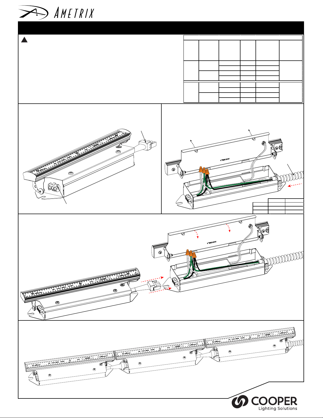
1. Unpack fixtures from box.
NOTE: If your installation calls for the jumper cable accessory to add space between
fixtures, make sure they are available.
Do not leave any other open holes in an enclosure of wiring or electrical components.
objects.
Male connector
2. Prepare beginning fixture for line voltage input by removing top screws to open
wiring compartment. Remove male connector wiring from fixture and discard.
Feed power lead cable (by others) through right side hole and trim to desired
length. Connect power lead cable and input driver wiring to female connector
wires via wire nuts. NOTE: Minimum of 18 AWG power lead cable wires to be
used.
Input
Voltage
(VAC)
120 VAC
277 VAC
LC32 Installation Run Length Specifications
Light Level Unit Length
Light Level 1
Light Level 2
Light Level 1
Light Level 2
N
G
12" (305mm) 0.16 60 (60')
24" (610mm) 0.16 60 (120')
12" (305mm) 0.16 60 (60')
24" (610mm) 0.32 30 (60')
12" (305mm) 0.08 120 (120 ')
24" (610mm) 0.08 120 (240 ')
12" (305mm) 0.08 120 (120 ')
24" (610mm) 0.16 60 (120')
L
Input
Current
(A)
Page 1 of 1
Max. Nu mber of
Units (Lin ear
Feet) to be
Interconnected
Max. Distance
Between
Interconnected
Units usi ng
Jumper Cable
12' (3.7m)
12' (3.7m)
Power lead cable
(by others)
Female connector
3. Close beginning fixture by tightening top screws. Attach the male
connector on the right side of the next fixture to the female connector of the
beginning fixture. Ensure connection is secure.
4. Continue to connect each additional fixture in the series using the
connectors. Do not exceed the maximum allowable run length (See table above).
No connector endcap is needed for final fixture.
Snap male connector into female
connector. To disconnect, squeeze
the side tabs on the male connector
Line (+) Black Brown
Neutral (-) White Blue
Ground Green Green/Yellow
120V 240V
Ametrix 18001 East Colfax Ave . Aurora, CO 80011 Ph. (303) 393-1522 Fax (303) 393-1477
ADY121846
 Loading...