

Page 1
Technical Note
XBT Rackmount Installation
Document No. M370187-05 Rev A • 7/3/2008
PURPOSE
Provide instructions for assembling XBT rackmount kit s.
PARTS
• rackmount piece
• filler panel
• M3.0 (3mm) screws (2 per benchtop unit; 3 pe r filler pan el)
• M5.0 (5mm) screws (4 per rackm ount)
TOOLS
Philips head screwdriver (not supplied with kit)
SUMMARY OF PROCEDURES
Remove feet from benchtop unit; attach rackmount parts (rackmount piece and filler panel if installing single unit), and insert and
secure to rack. See Figure 10 and Figure 11, for dim ensions drawings in last section of this document.
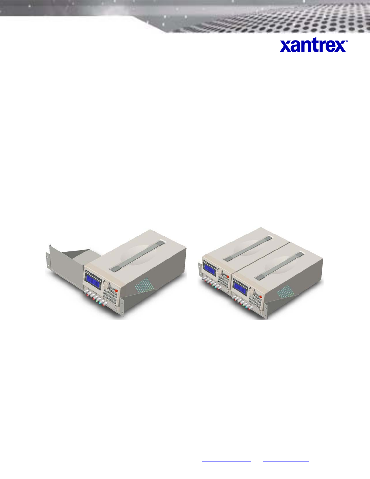
Assembled Rackmounts: Single (Figure 1) and Duo (Figure 2).
Figure 1. Rackmount with Single Unit and Filler Panel Figure 2. Rackmount with Two Units
PROCEDURES
1. On an appropriate work surface (f lat and sturdy), p lace unit with bottom face up.
2. Remove rubber pads from each of fo ur feet.
Unscrew and remove four feet. (Recommend keeping together rubber pads, screws and feet in event that
3.
unit is ever needed for benchtop use).
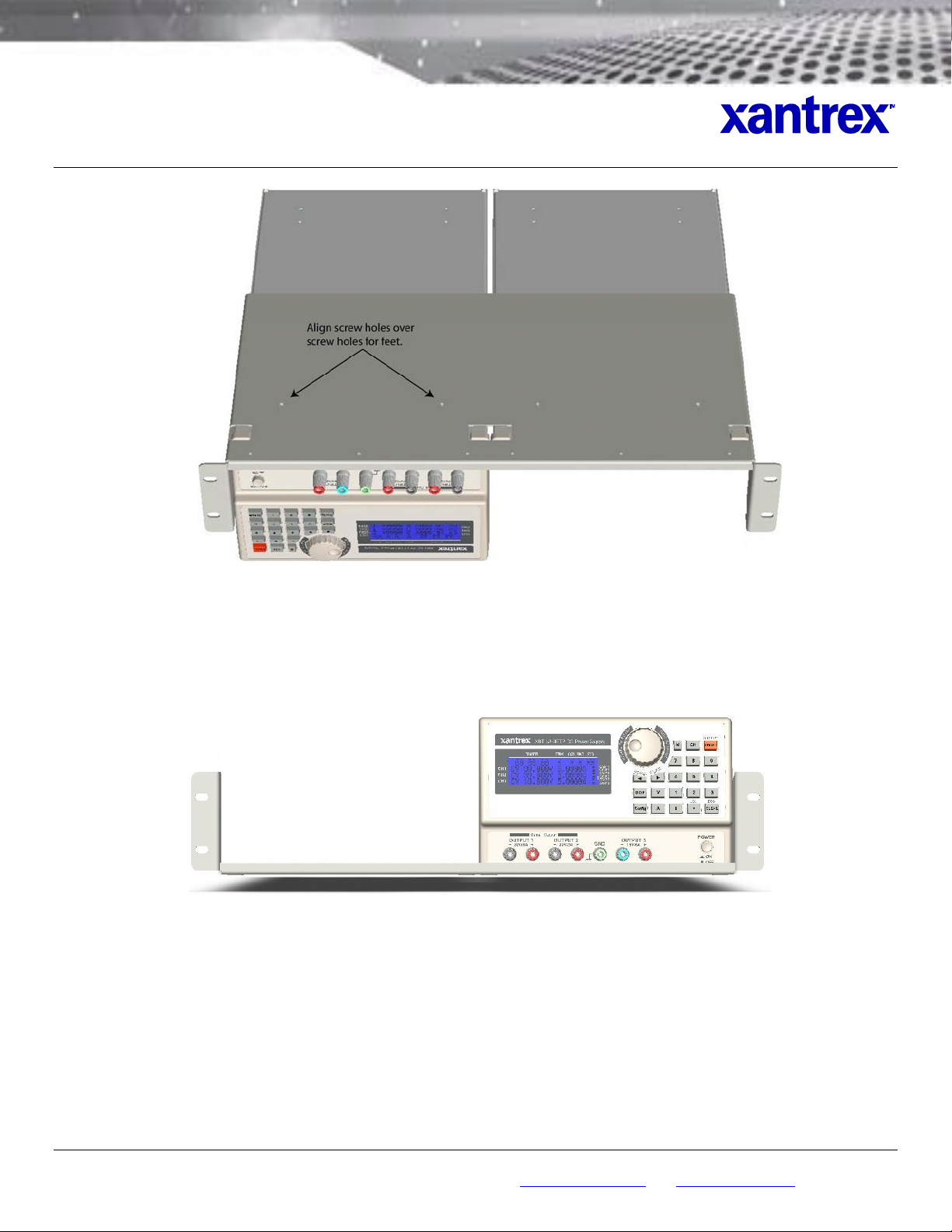
4. With unit still in bottom-up position, lay rackmount piece on unit with its front lip overhanging front of unit and
one side (right or left) flush against same (corresponding) side of unit, and with screw holes on rackmount
piece aligned with holes where feet were removed from unit (
©2008 Programmable Div ision of Xa ntrex Tech nology Inc. • All r ights res erved. • X antrex is a tr ademark of Xantrex Internati onal, register ed in th e U.S. and other countri es.
9250 Brown Deer Road, Sa n Diego CA 92121 • Tel: 858-4 50-008 5 • Fax: 8 58-458-0 267 • em ail: sal es@progra mmablep ower.com • Web: www.programm ablepow er.com
Figure 3).
1 of 6
Page 2
Technical Note
XBT Rackmount Installation
Document No. M370187-05 Rev A • 7/3/2008
Figure 3. Unit, Bottom Up, with Main Rackmount Piece Aligned
5. Use screwdriver to secure rackmount piece to unit with two (2) M3.0 screws.
6. If installing two supplies, repeat Steps 1-6, then skip to Step 12. For a single unit, con tinue with Step 8 .
7. Turn assembled unit and rackmount piece so that unit’s top is face up and rackmount piece is lying on work
surface (
Figure 4).
Figure 4. Unit, Top Up, Secured to Main Rackmount Piece
8. Set filler panel (
Figure 5) in blank space next to unit, flush with side and front lip of rackmount piece (Figure 6).
©2008 Programmable Div ision of Xa ntrex Tech nology Inc. • All r ights res erved. • X antrex is a tr ademark of Xantrex Internati onal, register ed in th e U.S. and other countri es.
9250 Brown Deer Road, Sa n Diego CA 92121 • Tel: 858-4 50-008 5 • Fax: 8 58-458-0 267 • em ail: sal es@progra mmablep ower.com • Web: www.programm ablepow er.com
2 of 6
Page 3

Technical Note
XBT Rackmount Installation
Document No. M370187-05 Rev A • 7/3/2008
Figure 5. Filler Panel
Figure 6. Filler Panel Placement
©2008 Programmable Div ision of Xa ntrex Tech nology Inc. • All r ights res erved. • X antrex is a tr ademark of Xantrex Internati onal, register ed in th e U.S. and other countri es.
9250 Brown Deer Road, Sa n Diego CA 92121 • Tel: 858-4 50-008 5 • Fax: 8 58-458-0 267 • em ail: sal es@progra mmablep ower.com • Web: www.programm ablepow er.com
3 of 6
Page 4

Technical Note
XBT Rackmount Installation
Document No. M370187-05 Rev A • 7/3/2008
9. Align screw holes at bottom of filler panel with screw holes of rackmount piece (Figure 7).
Figure 7. Screw Holes for Filler Panel (from top, insert screws through filler panel first)
Figure 8. Filler Panel Installed
10. Use screwdriver to secure filler panel to rackmount piece with three (3) M3.0 screws.
11. Slide entire assembly, rear first, into rack.
12. Align screw holes of left and right sides of rackmount piece (
Figure 9) with corresponding screw holes of rack.
©2008 Programmable Div ision of Xa ntrex Tech nology Inc. • All r ights res erved. • X antrex is a tr ademark of Xantrex Internati onal, register ed in th e U.S. and other countri es.
9250 Brown Deer Road, Sa n Diego CA 92121 • Tel: 858-4 50-008 5 • Fax: 8 58-458-0 267 • em ail: sal es@progra mmablep ower.com • Web: www.programm ablepow er.com
4 of 6
Page 5

Technical Note
XBT Rackmount Installation
Document No. M370187-05 Rev A • 7/3/2008
Figure 9. Screw Holes for Securing Assembly to Rack
13. Use screwdriver to secure assembly to rack with four (4) M5.0 screws p rovided.
DIMENSIONS DRAWINGS
Figure 10. Filler Panel Dimensions
©2008 Programmable Div ision of Xa ntrex Tech nology Inc. • All r ights res erved. • X antrex is a tr ademark of Xantrex Internati onal, register ed in th e U.S. and other countri es.
9250 Brown Deer Road, Sa n Diego CA 92121 • Tel: 858-4 50-008 5 • Fax: 8 58-458-0 267 • em ail: sal es@progra mmablep ower.com • Web: www.programm ablepow er.com
5 of 6
Page 6

Technical Note
XBT Rackmount Installation
Document No. M370187-05 Rev A • 7/3/2008
Figure 11. Rackmount Dimensions
©2008 Programmable Div ision of Xa ntrex Tech nology Inc. • All r ights res erved. • X antrex is a tr ademark of Xantrex Internati onal, register ed in th e U.S. and other countri es.
9250 Brown Deer Road, Sa n Diego CA 92121 • Tel: 858-4 50-008 5 • Fax: 8 58-458-0 267 • em ail: sal es@progra mmablep ower.com • Web: www.programm ablepow er.com
6 of 6
 Loading...