

Page 1

Via Acquanera, 29 22100 Como
tel. 031.526.566 (r.a.) fax 031.507.984
info@calpower.it www.calpower.it
i Series
iX Series
AC Power Source
User Manual
Contact Information
Telephone: 800 733 5427 (toll free in North America)
858 450 0085 (direct)
Fax: 858 458 0267
Email:
Domestic Sales: domorders.sd@ametek.com
International Sales: intlorders.sd@ametek.com
Customer Service: service.ppd@ametek.com
Web: www.programmablepower.com
March 2011 Document No. 7000-970 Rev. AA
Page 2

Page 3

Page 4

User's Manual
AC Power Source
California Instruments
Models :
3001i
5001i
5001i-400
9003i
10001i
10001i-400
15001i
15001i-400
15003i
15003i-400
30003i
30003i-400
3001iX
5001iX
5001iX-400
9003iX
10001iX
10001iX-400
15001iX
15001iX-400
15003iX
15003iX-400
30003iX
30003iX-400
Rev AA, March 2011.
Page 5

About AMETEK
AMETEK Programmable Power, Inc., a Division of AMETEK, Inc., is a global leader in the design
and manufacture of precision, programmable power supplies for R&D, test and measurement,
process control, power bus simulation and power conditioning applications across diverse
industrial segments. From bench top supplies to rack-mounted industrial power subsystems,
AMETEK Programmable Power is the proud manufacturer of Elgar, Sorensen, California
Instruments and Power Ten brand power supplies.
AMETEK, Inc. is a leading global manufacturer of electronic instruments and electromechanical
devices with annualized sales of $2.5 billion. The Company has over 11,000 colleagues working
at more than 80 manufacturing facilities and more than 80 sales and service centers in the United
States and around the world.
Trademarks
AMETEK is a registered trademark of AMETEK, Inc.
Other trademarks, registered trademarks, and product names are the property of their respective
owners and are used herein for identification purposes only.
Notice of Copyright
i Series, iX Series AC Power Source, User Manual
rights reserved.
© 2010 AMETEK Programmable Power, Inc. All
Exclusion for Documentation
UNLESS SPECIFICALLY AGREED TO IN WRITING, AMETEK PROGRAMMABLE POWER, INC.
(“AMETEK”):
(a) MAKES NO WARRANTY AS TO THE ACCURACY, SUFFICIENCY OR SUITABILITY OF ANY
TECHNICAL OR OTHER INFORMATION PROVIDED IN ITS MANUALS OR OTHER
DOCUMENTATION.
(b) ASSUMES NO RESPONSIBILITY OR LIABILITY FOR LOSSES, DAMAGES, COSTS OR
EXPENSES, WHETHER SPECIAL, DIRECT, INDIRECT, CONSEQUENTIAL OR INCIDENTAL,
WHICH MIGHT ARISE OUT OF THE USE OF SUCH INFORMATION. THE USE OF ANY SUCH
INFORMATION WILL BE ENTIRELY AT THE USER’S RISK, AND
(c) REMINDS YOU THAT IF THIS MANUAL IS IN ANY LANGUAGE OTHER THAN ENGLISH,
ALTHOUGH STEPS HAVE BEEN TAKEN TO MAINTAIN THE ACCURACY OF THE
TRANSLATION, THE ACCURACY CANNOT BE GUARANTEED. APPROVED AMETEK CONTENT
IS CONTAINED WITH THE ENGLISH LANGUAGE VERSION, WHICH IS POSTED AT
WWW.PROGRAMMABLEPOWER.COM.
Date and Revision
March 2011 Revision AA
Part Number
7000-970
Contact Information
Telephone: 800 733 5427 (toll free in North America)
858 450 0085 (direct)
Fax: 858 458 0267
Email: sales@programmablepower.com
service@programmablepower.com
Web: www.programmablepower.com
i
Page 6

This page intentionally left blank.
ii
Page 7
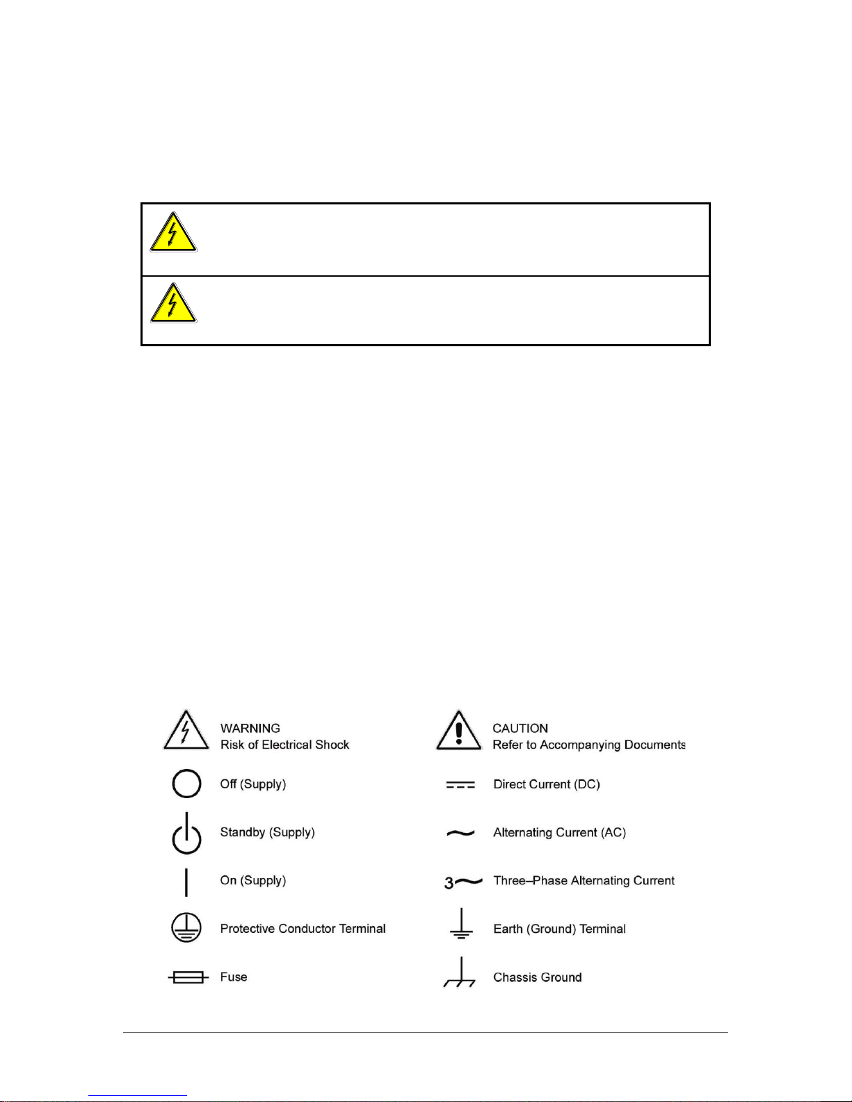
WARNING
Hazardous voltages may be present when covers are removed. Qualified
personnel must use extreme caution when servicing this equipment.
Circuit boards, test points, and output voltages also may be floating above
(below) chassis ground.
WARNING
The equipment used contains ESD sensitive ports. When installing
equipment, follow ESD Safety Procedures. Electrostatic discharges might
cause damage to the equipment.
Important Safety Instructions
Before applying power to the system, verify that your product is configured properly for your
particular application.
Only qualified personnel who deal with attendant hazards in power supplies, are allowed to perform
installation and servicing.
Ensure that the AC power line ground is connected properly to the Power Rack input connector or
chassis. Similarly, other power ground lines including those to application and maintenance
equipment must be grounded properly for both personnel and equipment safety.
Always ensure that facility AC input power is de-energized prior to connecting or disconnecting any
cable.
In normal operation, the operator does not have access to hazardous voltages within the chassis.
However, depending on the user’s application configuration, HIGH VOLTAGES HAZARDOUS TO
HUMAN SAFETY may be normally generated on the output terminals. The customer/user must
ensure that the output power lines are labeled properly as to the safety hazards and that any
inadvertent contact with hazardous voltages is eliminated.
Guard against risks of electrical shock during open cover checks by not touching any portion of the
electrical circuits. Even when power is off, capacitors may retain an electrical charge. Use safety
glasses during open cover checks to avoid personal injury by any sudden component failure.
Neither AMETEK Programmable Power Inc., San Diego, California, USA, nor any of the subsidiary
sales organizations can accept any responsibility for personnel, material or inconsequential injury,
loss or damage that results from improper use of the equipment and accessories.
SAFETY SYMBOLS
iii
Page 8

Product Family: i Series, iX Series
Warranty Period: One Year
WARRANTY TERMS
AMETEK Programmable Power, Inc. (“AMETEK”), provides this written warranty covering the
Product stated above, and if the Buyer discovers and notifies AMETEK in writing of any defect in
material or workmanship within the applicable warranty period stated above, then AMETEK may,
at its option: repair or replace the Product; or issue a credit note for the defective Product; or
provide the Buyer with replacement parts for the Product.
The Buyer will, at its expense, return the defective Product or parts thereof to AMETEK in
accordance with the return procedure specified below. AMETEK will, at its expense, deliver the
repaired or replaced Product or parts to the Buyer. Any warranty of AMETEK will not apply if the
Buyer is in default under the Purchase Order Agreement or where the Product or any part
thereof:
is damaged by misuse, accident, negligence or failure to maintain the same as
specified or required by AMETEK;
is damaged by modifications, alterations or attachments thereto which are not
authorized by AMETEK;
is installed or operated contrary to the instructions of AMETEK;
is opened, modified or disassembled in any way without AMETEK’s consent; or
is used in combination with items, articles or materials not authorized by AMETEK.
The Buyer may not assert any claim that the Products are not in conformity with any warranty
until the Buyer has made all payments to AMETEK provided for in the Purchase Order Agreement.
PRODUCT RETURN PROCEDURE
1. Request a Return Material Authorization (RMA) number from the repair facility (must be
done in the country in which it was purchased):
In the USA, contact the AMETEK Repair Department prior to the return of the
product to AMETEK for repair:
Telephone: 800-733-5427, ext. 2295 or ext. 2463 (toll free North America)
858-450-0085, ext. 2295 or ext. 2463 (direct)
Outside the United States, contact the nearest Authorized Service Center
(ASC). A full listing can be found either through your local distributor or our
website, www.programmablepower.com, by clicking Support and going to the
Service Centers tab.
2. When requesting an RMA, have the following information ready:
Model number
Serial number
Description of the problem
NOTE: Unauthorized returns will not be accepted and will be returned at the shipper’s expense.
NOTE: A returned product found upon inspection by AMETEK, to be in specification is subject to
an evaluation fee and applicable freight charges.
iv
Page 9

Table of Contents
1. Introduction .................................................................................................................................. 1
1.1 General Description ............................................................................................................................... 1
2. Specifications ............................................................................................................................... 2
2.1 Electrical ................................................................................................................................................ 2
2.2 Mechanical .......................................................................................................................................... 10
2.3 Environmental ...................................................................................................................................... 10
2.4 Regulatory ........................................................................................................................................... 12
2.5 Front Panel Controls ............................................................................................................................ 12
2.6 Special Features, Options and Accessories ........................................................................................ 13
3. Unpacking and Installation ....................................................................................................... 15
3.1 Unpacking............................................................................................................................................ 15
3.2 Power Requirements ........................................................................................................................... 15
3.3 Mechanical Installation ........................................................................................................................ 16
3.4 Input Wiring – TB1 ............................................................................................................................... 16
3.5 Output Power Connections – TB2 ....................................................................................................... 16
3.6 Connectors - Rear Panel ..................................................................................................................... 18
3.7 Single-Phase and Three Phase Multiple Box System Configurations ................................................. 26
3.8 Output Voltage Ranges ....................................................................................................................... 26
3.9 Functional Test .................................................................................................................................... 27
4. Front Panel Operation ............................................................................................................... 37
4.1 Tour of the Front Panel ........................................................................................................................ 37
4.2 Menu Structure .................................................................................................................................... 42
4.3 Output Programming ........................................................................................................................... 77
4.4 Waveform Management [iX Series only] ............................................................................................. 78
4.5 Standard Measurements ..................................................................................................................... 83
4.6 Advanced Measurements [iX Series only] ........................................................................................... 85
4.7 Transient Programming ....................................................................................................................... 94
5. Principle of Operation .............................................................................................................. 101
5.1 General ................................................................................................................................ .............. 101
5.2 Overall Description ............................................................................................................................ 102
5.3 Oscillator Assembly ........................................................................................................................... 102
5.4 Current Limit Board ........................................................................................................................... 105
5.5 Auxiliary Power Supply ...................................................................................................................... 105
5.6 DC-DC Power Converter ................................................................................................................... 106
5.7 AC Control Logic ............................................................................................................................... 106
5.8 AC Power Board ................................................................................................................................ 109
5.9 Input/Output Board ............................................................................................................................ 109
6. Calibration ................................................................................................................................ 113
6.1 Calibration Equipment ....................................................................................................................... 113
6.2 The Output Calibration Screen .......................................................................................................... 113
6.3 The Measurement Calibration Screen ............................................................................................... 113
6.4 Routine Output Calibration ................................................................................................................ 114
6.5 Routine Measurement Calibration ..................................................................................................... 117
6.6 Non-Routine Calibration .................................................................................................................... 120
7. Service ...................................................................................................................................... 125
7.1 Cleaning ............................................................................................................................................ 125
7.2 General ................................................................................................................................ .............. 125
7.3 Basic operation .................................................................................................................................. 125
7.4 Advanced Troubleshooting. ............................................................................................................... 127
i Series / iX Series v
Page 10

8. Top Assembly Replaceable Parts........................................................................................... 131
9. Options ..................................................................................................................................... 133
9.1 RTCA/DO-160 Option ...................................................................................................................... 133
9.2 IEC 61000-4-11 Option ..................................................................................................................... 180
9.3 IEC 61000-4-13 Option ..................................................................................................................... 187
9.4 EOS Option ....................................................................................................................................... 199
9.5 Mode iX Option ................................................................................................................................. 214
9.6 Omni Options .................................................................................................................................... 222
9.7 LNS Option and XLS Option ............................................................................................................. 233
9.8 Option –704: MilStd704 Tests ........................................................................................................... 239
9.9 ABD Option: Airbus ABD0100.1.8 Test ............................................................................................. 289
9.10 WHM Option ..................................................................................................................................... 317
10. Error Messages ........................................................................................................................ 320
11. Index .......................................................................................................................................... 325
vi i Series / iX Series
Page 11

List of Figures
Figure 3-1: The 5001iX Power Source ................................................................................................................ 15
Figure 3-2: RS232C Cable for PC Connection wiring diagram. .......................................................................... 21
Figure 3-3: Function Strobe Connection. ............................................................................................................ 22
Figure 3-4: Function Strobe / Trigger Output Accessory. .................................................................................... 22
Figure 3-5: Rear Panel View for the 3001i/3001iX ............................................................................................. 24
Figure 3-6: Rear Panel View for the 5001i/5001iX ............................................................................................. 25
Figure 3-7: Connection For Single Power Source (5001iX/i, 3001iX/i) ................................................................ 28
Figure 3-8: Functional Test Setup ....................................................................................................................... 29
Figure 3-9: Single Phase 10000 VA System (10001iX/i) .................................................................................... 30
Figure 3-10: Three Phase 15000 VA System (15003iX/i-LK Three Controllers) ................................................ 31
Figure 3-11: Single Phase 15000 VA System (15001iX/i) .................................................................................. 32
Figure 3-12: Three-Phase 15000 VA system (15003iX/i - One Controller) ........................................................ 33
Figure 3-13: Connection With MODE Option ..................................................................................................... 34
Figure 3-14: Two Phase 10000 VA System (10002i-LK Two Controllers) ......................................................... 35
Figure 3-15: Three-Phase 9000 VA System (9003iX/i – One Controller) ........................................................... 36
Figure 4-1: Shuttle Knob ..................................................................................................................................... 38
Figure 4-2: FUNCTION keypad .......................................................................................................................... 39
Figure 4-3: Entering value from decimal keypad ................................................................................................ 40
Figure 4-4: Cursor UP key movement ................................................................................................................ 41
Figure 4-5: Cursor DOWN key movement ......................................................................................................... 41
Figure 4-6: Main Menu 1 screen ......................................................................................................................... 42
Figure 4-7: Menu 1 through 3 ............................................................................................................................. 42
Figure 4-8: PROGRAM Menu ............................................................................................................................. 46
Figure 4-9: MEASUREMENTS Screen, single phase and three phase modes .................................................. 48
Figure 4-10: HARMONICS/TRACE ANALYSIS screen ...................................................................................... 50
Figure 4-11: TRANSIENTS menu ...................................................................................................................... 53
Figure 4-12: VOLTAGE SURGE/SAG SETUP screen ....................................................................................... 54
Figure 4-13: VOLTAGE SWEEP/STEP SETUP screen ..................................................................................... 56
Figure 4-14: FREQUENCY SWEEP/STEP SETUP screen ................................................................................ 58
Figure 4-15: VOLTAGE/FREQUENCY SWEEP/STEP SETUP screen .............................................................. 59
Figure 4-16: START/VIEW TRANSIENT SEQUENCE screen ............................................................................ 60
Figure 4-17: WAVEFORMS menu ..................................................................................................................... 61
Figure 4-18: APPLICATIONS menu ................................................................................................................... 64
Figure 4-19: SETUP REGISTERS menu ............................................................................................................ 65
Figure 4-20: UTILITY menu ................................................................................................................................ 66
Figure 4-21: GPIB/RS232 SETUP menu ............................................................................................................ 68
Figure 4-22: VOLTAGE/CURRENT CONTROL SETUP menu ........................................................................... 69
Figure 4-23: INITIAL SETUP menus ................................................................................................................... 70
Figure 4-24:LIMIT SETUP menu ......................................................................................................................... 72
Figure 4-25: OUTPUT IMPEDANCE menu ......................................................................................................... 74
Figure 4-26: MEASUREMENT CAL FACTORS menu ........................................................................................ 75
Figure 4-27: OUTPUT CAL FACTORS menu ..................................................................................................... 76
Figure 4-28: Selecting a waveform ...................................................................................................................... 78
Figure 4-29: Selecting waveforms for single phase or all phases ...................................................................... 79
Figure 4-30: Custom waveform creation with GUI program ................................................................................ 80
Figure 4-31: Waveform crest factor affects max. rms voltage ............................................................................. 81
Figure 4-32: Waveform frequency domain view mode ....................................................................................... 82
Figure 4-33: Scrolling through tabular FFT data ................................................................................................ 86
Figure 4-34: Scrolling through bar chart FFT data ............................................................................................. 86
Figure 4-35: Scrolling through acquired waveform data ..................................................................................... 88
Figure 4-36: SET VOLT trigger source acquisition ............................................................................................. 90
Figure 4-37: Positive trigger delay (Post trigger data) ........................................................................................ 92
Figure 4-38: Negative trigger delay (Pre-trigger data) ........................................................................................ 93
Figure 4-39: Pulse Transients ............................................................................................................................ 95
Figure 4-40: List Transients ................................................................................................................................ 96
Figure 4-41: Switching waveforms in a transient list .......................................................................................... 99
Figure 4-42: START/VIEW TRANSIENT SEQUENCE menu ........................................................................... 100
Figure 5-1: AC Power System Block Diagram .................................................................................................. 101
Figure 5-2: Power Source Module Block Diagram ........................................................................................... 104
Figure 5-3: 5001i Internal Layout ..................................................................................................................... 107
Figure 5-4: Logic Board LED's .......................................................................................................................... 108
i Series / iX Series vii
Page 12

Figure 5-5: AC Power Stage Layout ................................................................................................................ 110
Figure 5-6: AC Control Logic Block Diagram ................................................................................................... 111
Figure 6-1: Test Equipment Hookup for Routine Output Calibration................................................................. 114
Figure 6-2: Test Equipment Hook-up for Measurement Calibration .................................................................. 118
Figure 6-3: Adjustment Location ....................................................................................................................... 124
Figure 9-1: Application Menu ............................................................................................................................ 135
Figure 9-2: DO160 Main Menu .......................................................................................................................... 135
Figure 9-3: Normal state ................................................................................................................................... 136
Figure 9-4: Voltage Modulation ........................................................................................................................ 138
Figure 9-5: Frequency Modulation .................................................................................................................... 139
Figure 9-6: Power Interrupt ............................................................................................................................... 140
Figure 9-7: Power Interrupt for Group 2 and 3 .................................................................................................. 141
Figure 9-8: Emergency Screen ......................................................................................................................... 142
Figure 9-9: Abnormal Screen ............................................................................................................................ 144
Figure 9-10: DO-160 DC Main Menu ................................................................................................................ 146
Figure 9-11: Normal State ................................................................................................................................. 146
Figure 9-12: Abnormal State ............................................................................................................................. 148
Figure 9-13: 160 Option Test Selection Screen. ............................................................................................... 156
Figure 9-14: 160 Option Test Control Screen. .................................................................................................. 160
Figure 9-15: DO160E DC Ripple Test Window. ................................................................................................ 162
Figure 9-16: 160 Option EUT Measurement Data Screen. ............................................................................... 163
Figure 9-17: Application menu .......................................................................................................................... 181
Figure 9-18: IEC1000-4-11 Menu ..................................................................................................................... 181
Figure 9-19: IEC Dips and Interrupts ................................................................................................................ 182
Figure 9-20: Voltage Variation screen .............................................................................................................. 184
Figure 9-21: EN 61000-4-11 Voltage Variation specification- Edition 1.0 ......................................................... 185
Figure 9-22: EN 61000-4-11 Voltage Variation specification- Edition 2.0 ......................................................... 185
Figure 9-23: IEC 61000-4-11 GUI screen. ........................................................................................................ 186
Figure 9-24: Application menu .......................................................................................................................... 188
Figure 9-25: IEC 61000-4-13 Menu .................................................................................................................. 188
Figure 9-26: IEC 61000-4-13 FCurve................................................................................................................ 190
Figure 9-27: IEC 61000-4-13 OSwing ............................................................................................................... 190
Figure 9-28: IEC 61000-4-13 Sweep ................................................................................................................ 191
Figure 9-29: IEC 61000-4-13 Harmonics .......................................................................................................... 192
Figure 9-30: IEC 61000-4-13 Inter harmonics .................................................................................................. 193
Figure 9-31: IEC 61000-4-13 Meister Curve ..................................................................................................... 194
Figure 9-32: IEC 61000-4-13 Test Flowchart Class 1 and 2 ............................................................................. 195
Figure 9-33: IEC 61000-4-13 Test Flowchart Class 3 ....................................................................................... 196
Figure 9-34: MENU 2 SCREEN ........................................................................................................................ 198
Figure 9-35: INTERHARMONICS SCREEN ..................................................................................................... 198
Figure 9-36: Example Connection With 5001iX and EOS-1 ............................................................................. 205
Figure 9-37: Example Connection With Compliance Test System and EOS-1 ................................................ 206
Figure 9-38: 15003iX-CTS-EOS3-LR3 .............................................................................................................. 207
Figure 9-39: 15003iX/3-EOS3 ........................................................................................................................... 208
Figure 9-40: EOS3 Location of 70/80 Taps for each phase. ............................................................................. 212
Figure 9-41: Example Connection With MODE iX ............................................................................................ 219
Figure 9-42: Example Connections With OMNI 1-18i ....................................................................................... 226
Figure 9-43: Example Connections With OMNI 3-18i ....................................................................................... 227
Figure 9-44: Schematic Showing OMNI 1-37i and1-37iJ Connected to 5001iX System................................... 228
Figure 9-45: Schematic Showing OMNI 3-37i Connected to 30003iX System ................................................. 229
Figure 9-46: Applications Screen ...................................................................................................................... 230
Figure 9-47: OMNI Control Screen ................................................................................................................... 231
Figure 9-48: OMNI Control Screen ................................................................................................................... 231
Figure 9-49: XLS Module Dimensions .............................................................................................................. 235
Figure 9-50: XLS Connection on Low Range .................................................................................................... 236
Figure 9-51: XLS Connection on High Range ................................................................................................ 237
Figure 9-52: Application Menu .......................................................................................................................... 241
Figure 9-53: MIL704 Menu ............................................................................................................................... 242
Figure 9-54: Steady State Menu ....................................................................................................................... 242
Figure 9-55: Transient Menu ............................................................................................................................. 244
Figure 9-56: Emergency Menu......................................................................................................................... 245
Figure 9-57: Abnormal Screen ......................................................................................................................... 246
Figure 9-58: MIL704 DC Menu .......................................................................................................................... 247
viii i Series / iX Series
Page 13

Figure 9-59: Steady State DC .......................................................................................................................... 247
Figure 9-60: Transient Menu ............................................................................................................................ 248
Figure 9-61: Abnormal Test Screen .................................................................................................................. 249
Figure 9-62: Emergency Test ............................................................................................................................ 250
Figure 9-63: 704 Option Test Selection Screen. ............................................................................................... 257
Figure 9-64: 704 Option Test Control Screen.................................................................................................... 261
Figure 9-65: 704 Option EUT Measurement Data Screen. ............................................................................... 264
Figure 9-66: ABD Option Test Selection Screen. .............................................................................................. 293
Figure 9-67: ABD Option Test Control Screen. ................................................................................................. 297
Figure 9-68: ABD Option EUT Measurement Data Screen. .............................................................................. 300
Figure 9-69: ABD0100.1.8 Switching Transient Control Window ...................................................................... 303
Figure 9-70: Application Screen ........................................................................................................................ 317
Figure 9-71 Watt-Hour Meter Screen ................................................................................................................ 317
Figure 9-72: WH-Meter Screen With Function Active ....................................................................................... 318
i Series / iX Series ix
Page 14

List of Tables
Table 3-1: Wire Sizes ........................................................................................................................................ 17
Table 3-2: System Interface Connector (J22) .................................................................................................... 18
Table 3-3: Remote Sense Connector – TB3 ....................................................................................................... 20
Table 3-4: RS232C Connector ............................................................................................................................ 21
Table 5-1: Logic Board LED‟s ........................................................................................................................... 109
Table 6-1: Output Calibration Table ................................................................................................................. 116
Table 6-2: Calibration Load For Each Phase .................................................................................................... 117
Table 6-3: Measurement Calibration Table ....................................................................................................... 119
Table 6-4: Gain Adjustments ............................................................................................................................ 120
Table 6-5: Current Limit Calibration .................................................................................................................. 120
Table 6-6: GPIB addresses for impedance calibration ..................................................................................... 121
Table 6-7: Programmable Z adjustment pots .................................................................................................... 122
Table 6-8: Formulas to calculate R and L ......................................................................................................... 122
Table 7-1: Basic Symptoms ............................................................................................................................. 125
Table 7-2: Auxiliary Power Supply Fuse Ratings ............................................................................................. 129
Table 8-1: Replaceable Parts .......................................................................................................................... 131
Table 8-2: Fuses ................................................................................................................................ .............. 132
Table 9-1: Normal Voltage and Frequency minimum ....................................................................................... 136
Table 9-2: Normal Voltage and Frequency Maximum ....................................................................................... 136
Table 9-3: Normal Voltage Unbalance .............................................................................................................. 137
Table 9-4: Normal VoltageSurge Sequence ..................................................................................................... 141
Table 9-5: Normal Frequency Transient Sequence .......................................................................................... 142
Table 9-6: Normal Frequency Variation Sequence ........................................................................................... 142
Table 9-7: Emergency Voltage and Frequency Minimum ................................................................................. 143
Table 9-8: Emergency Voltage and Frequency Maximum ................................................................................ 143
Table 9-9: Emergency Voltage Unbalance ....................................................................................................... 143
Table 9-10: Abnormal Voltage Minimum ........................................................................................................... 144
Table 9-11: Abnormal Voltage Maximum .......................................................................................................... 144
Table 9-12: Abnormal Frequency Transient...................................................................................................... 145
Table 9-13: Normal Voltage Minimum............................................................................................................... 146
Table 9-14: Normal Voltage Maximum .............................................................................................................. 147
Table 9-15: Voltage Surge ................................................................................................................................ 147
Table 9-16: Abnormal Voltage Surge ................................................................................................................ 149
Table 9-17: -160 Option Test Coverage, 115VAC and 28VDC ......................................................................... 151
Table 9-18: -160 Option Test Coverage, 230VAC and 14VDC ......................................................................... 152
Table 9-19: Dips and Interruptions Tests Performed During RUN ALL ........................................................... 183
Table 9-20: Voltage Variations Test Performed During RUN ALL ................................................................... 184
Table 9-21: EOS Versions ................................................................................................................................ 199
Table 9-22: -704 Option Test Coverage ................................................................................................ ............ 253
Table 9-23: -ABD Option Test Coverage .......................................................................................................... 290
Table 10-1: Error Messages.............................................................................................................................. 324
x i Series / iX Series
Page 15

User Manual
1. Introduction
This instruction manual contains information on the installation, operation, calibration and
maintenance of all power systems that use the 3001i, 5001i, 3001iX, and 5001iX power sources
with the programmable controller. Higher power configurations consisting of multiple units
operated in parallel are also covered by this user manual. Such models are 10001iX, 10002iX,
15003iX and 30003iX.
1.1 General Description
The 3001i, 5001i, 3001iX, and 5001iX are high efficiency, lightweight AC power sources that
provide a precise output with low distortion. Older generation i Series have two voltage ranges,
either 0-135V or 0-270V. The iX Series and the newer generation i Series offer two sets of
ranges, 0-135/0-270 and 0-150/0-300. Full power is available at the maximum output voltage for
all ranges. Two or three 5001i/iX units can be connected in parallel as a single-phase system for
10 kVA or 15 kVA respectively. Three or six units can be connected as a three-phase system.
They can be operated with AC or DC output. The iX Series also offers AC+DC output mode.
i Series / iX Series 1
Page 16

User Manual
Parameter
3001i & Ix
5001i & iX
Line Voltage:
208-240 10% VAC, single phase
208-240 VLL 10%, (Standard)
400-440 VLL 10%, (-400)
400-480 V
LL
10%, (-400)
3 phase, 3 wire + ground
Line VA:
5000VA
8000VA
Line Current:
25 A RMS max. (Per Box)
23 A RMS max. at 208-240 VAC
12 A RMS max. at 400-440 VAC
and 400-480 VAC (Per Box)
Line Frequency:
50-60 Hz 10%
Efficiency:
80% (typical) depending on line and load
Power Factor:
0.7 (typical)
0.9 (typical)
Inrush Current:
100 Apk for 100 s
100 Apk for 100 s at 208-240V
50 A
pk
for 100 s at 400-440 VAC
and 400-480 VAC
Hold-Up Time:
15 ms
Isolation Voltage:
2200 VAC input to output
1350 VAC input to chassis
2. Specifications
All specifications are for a single i or iX series chassis and 25 5 C sine wave output with a
resistive load unless noted otherwise.
2.1 Electrical
2.1.1 Input
2 i Series / iX Series
Page 17

User Manual
Output Parameter
i Series
iX Series
Modes:
AC, DC
AC, DC, AC+DC
Voltage:
Ranges (L-N):
AC Mode
Low: 0 - 135 VAC / High: 0 - 270 VAC
0 - 150 VAC / High: 0 - 300 VAC
DC Mode
Low: 0 - 135 VDC / High: 0 - 270 VDC
0 - 150 VDC / High: 0 - 300 VDC
AC+DC Mode
iX Models only.
AC: Low: 0 - 150 V / High: 0 - 300 V
DC Offset: Low 0 - 150 V / High; 0 - 250 V
Programming
Resolution:
AC Mode
0.1 V
DC Mode
0.1 V
AC+DC Mode
AC: 01. V
DC Offset: 0.01 V < 0.5 V
0.1 V 0.6 - 25 V
1 V > 25 V
Voltage Accuracy:
AC mode
0.5% of range, 16 to 400 Hz.
0.5% of range, 16 to 400 Hz.
DC mode
0.5% of range
0.5% of range
DC offset
(AC+DC mode)
5% of range ± 0.1 VDC.< 25VDC
5% of range ± 1 VDC.> 25VDC
Voltage Distortion 1:
(linear load)
1% max THD at 50/60 Hz
2% max THD at 400 Hz
1% max THD at 50/60 Hz
2% max THD at 400 Hz
Load Regulation:
0.5% DC to 100 Hz
2.2% to 500 Hz (135 range)
0.6% to 500 Hz (270 range)
0.5% DC to 100 Hz.
2.2% to 500 Hz (135/150 range)
0.6% to 500 Hz (270/300 range)
Line Regulation:
0.1% for 10% input line
change
0.1% for 10% input line change
Power: (per phase, either range, at full scale voltage)
3001, 9003i/iX
5001, 15003i/iX
10001i/iX
3000 VA AC, 2100 W DC
5000 VA AC, 3500 W DC
10000 VA AC, 7000 W DC
3000 VA AC, 2100 W DC
5000 VA AC, 3500 W DC
10000 VA AC, 7000 W DC
2.1.2 Output
(ALL SPECIFICATIONS ARE FOR AC AND DC UNLESS NOTED OTHERWISE)
1
The distortion specification for the 3001i and iX is valid for an input voltage range of 197-264 V.
i Series / iX Series 3
Page 18

User Manual
Output Parameter
i Series
iX Series
15001i/iX
15000 VA AC, 10500 W DC
15000 VA AC, 10500 W DC
Current, maximum rms amps per phase:
3001i/iX
22.2, 135 VAC range
11.1, 270 VAC range
22.2, 135 VAC range
20.0, 150 VAC range
11.1, 270 VAC range
10.0, 300 VAC range
15.5, 135 VDC range
7.77, 270 VDC range
15.5, 135 VDC range
14.0, 150 VDC range
7.77, 270 VDC range
7.00, 300 VDC range
Current, maximum rms amps per phase:
5001, 15003i/iX
per phase
37.0, 135 VAC range
18.5, 270 VAC range
37.0, 135 VAC range
33.3, 150 VAC range
18.5, 270 VAC range
16.7, 300 VAC range
25.0, 135 VDC range
11.7, 270 VDC range
25.9, 135 VDC range
23.3, 150 VDC range
12.95, 270 VDC range
11.69, 300 VDC range
10001i/iX
74.0, 135 VAC range
37.0, 270 VAC range
74.0, 135 VAC range
66.7, 150 VAC range
37.0, 270 VAC range
33.3, 300 VAC range
51.8, 135 VDC range
25.9, 270 VDC range
51.8, 135 VDC range
46.6, 150 VDC range
25.9, 270 VDC range
23.3, 300 VDC range
4 i Series / iX Series
Page 19

User Manual
Output Parameter
i Series
iX Series
15001i/iX
111, 135 VAC range
55.5, 270 VAC range
111, 135 VAC range
100, 150 VAC range
55.5, 270 VAC range
50.0, 300 VAC range
77.7, 135 VDC range
38.8, 270 VDC range
77.7, 135 VDC range
70.0, 150 VDC range
38.8, 270 VDC range
35.0, 300 VDC range
(Derated linearly from 50% of voltage to 10% of specified current at 5% of voltage range)
Note: For the iX series, the current output in the AC & DC mode is equal to the current in the AC mode if the DC
voltage is less than 20% of the fullscale voltage. It is equal to the DC current for DC voltages more than 20% of
fullscale
i Series / iX Series 5
Page 20

User Manual
Output Parameter
i Series
iX Series
Current Limit
programmable 0 to 100% of range for all ranges
Frequency Range:
16.00 - 81.91 Hz (0.01 Hz resolution)
81.0 - 500.0 Hz (0.1 Hz resolution)
Frequency Accuracy:
0.01% of programmed value
DC Offset Voltage:
Less than 20 mV with linear load.
Output Impedance
Range:
n/a
R
min
to 1000 m
L
min
to 1000 H
Resolution:
n/a
4 m
4 H
Accuracy:
n/a
2% F.S. at 796 H and 400 m
Output Noise:
(20 kHz to 1 MHz)
400 mVrms max, 135 V
range,
800 mVrms max, 270 V range
<250 mV rms (typ),
<500 mV rms (max)
Peak Rep AC Current:
3001i/iX
5001i/iX
9003i/iX
15003i/iX
110 A for 135 V range,
92 A for 270 V range
110 A for 135 V range,
100 A for 150 V range,
92 A for 270 V range,
83 A for 300 V range
10001i/iX
220 A for 135 V range,
184 A for 270 V range
220 A for 135 V range,
200 A for 150 V range,
184 A for 270 V range,
166 A for 300 V range
15001i/iX
330 A for 135 V range,
276 A for 270 V range
330 A for 135 V range,
300 A for 150 V range,
276 A for 270 V range,
249 A for 300 V range
Crest Factor:
Up to 5:1
Up to 5:1
6 i Series / iX Series
Page 21

User Manual
Parameter
Range
Accuracy ( )
Resolution
Frequency
16.00 - 99.99 Hz
100.0 - 500.0 Hz
0.02 Hz
0.2 Hz
0.01 Hz
0.1 Hz
Rms Voltage
0 - 300 Volts
0.5V
0.01 Volt
Rms Current
0 - 40 Amps
0.5A
0.001 Amp
Peak Current
0 - 119 Amps
0.5A
0.001 Amp
VA Power
0 - 6.000 kVA
0.2 kVA
0.001 kVA
Real Power
0 - 6.000 kW
0.05 kW
0.001 kW
Power Factor
(>0.2kVA)
0 - 1.00
0.02
0.01
Current and Power Accuracy specifications are times ten for 10001i and 15001i. For 10001i and 15001i, resolution
decreases by factor of 10, ranges for current and power increases by factor of ten.
Parameter
Range
Accuracy ( )
Resolution
Frequency
16.00 - 500.0 Hz
0.01% + 0.01 Hz
0.01 to 81.91 Hz
0.1 to 500 Hz
RMS Voltage
0 - 300 Volts
0.05V + 0.02%, <100 Hz
0. 1V + 0.02%, 100-500 Hz
0.01 Volt
RMS Current
0 - 40 Amps
0.05A + 0.02%, <100 Hz
0. 1A + 0.02%, 100-500 Hz
0.001 Amp
Peak Current
0 - 119 Amps
0.05A + 0.02%, <100 Hz
0. 1A + 0.02%, 100-500 Hz
0.001 Amp
VA Power
0 - 6.000 kVA
0.01kVA + 0.02%, <100 Hz
0. 02kVa + 0.02%, 100-500 Hz
0.001 kVA
Real Power
0 - 6.000 kW
0.005kW + 0.02%, <100 Hz
0.01kW + 0.02%, 100-500 Hz
0.001 kW
Power Factor
(>0.2kVA)
0 - 1.00
0.01
2.1.3 Measurements (i series)
2.1.4 AC Measurements (iX series)
i Series / iX Series 7
Page 22

User Manual
Parameter
Range
Accuracy ( )
Resolution
Voltage
0 – 300 Volts
0.1 Volts
0.01 Volt
Current
0 – 40 Amps
0.01 Amps
0.001 Amp
Power
0 – 6.000 kW
0.05 kW
0.001 kW
Current and Power Accuracy specifications are times two for 10001iX and times three for 15001iX. For 10001iX and
15001iX, resolution decreases by factor of 10, ranges for current and power increases by factor of three.
Parameter
Range
Accuracy ( )
Resolution
Frequency fundamental
16.00 - 500 Hz
0.01% + 0.01 Hz
0.01 Hz
Frequency harmonics
32.00 Hz - 19.5 kHz
2 typ.
0.5
Voltage
Fundamental
0.25V
0.01V
Harmonic 2 - 50
0.25V + 0.1% +
0.1%/kHz
0.01V
Current
Fundamental
0.05A
0.01A
Harmonic 2 - 50
0.05A + 0.1% +
0.1%/kHz
0.01A
Accuracy specifications are times three for three phase mode. Harmonics frequency range in three phase mode is
32 Hz - 6.67 kHz. Resolution decreases by factor of 10 for 10001iX and 15001iX.
Parameter
Specification
External
Modulation:
0 to 10%
Synchronization
Input:
Isolated TTL input for external frequency control. Requires 5V at 5 ma
for logic high.
Trigger Output:
400 s pulse for voltage or frequency change. Isolated output that
requires a pull-up resistor, 22K , to + 5 VDC.
Non volatile
memory storage:
8 complete instrument setups and transient lists, 32 events per list.
Waveforms
Sine (i series)
Sine, square, clipped, user defined (iX series)
2.1.5 DC Measurements (iX series)
2.1.6 Harmonic Measurements (iX series)
2.1.7 System Specification
8 i Series / iX Series
Page 23

User Manual
Parameter
Specification
Transient
Voltage: drop, step, sag, surge, sweep
Frequency: step, sag, surge, sweep
Voltage and Frequency: step, sweep
IEEE-488 Interface:
SH1, AH1, T6, L3, SR1, RL2, DC1, DT1
IEEE 488.2 and SCPI
Response time is 10 ms (typical)
RS232C Interface:
Bi-directional serial interface
9 pin D-shell connector
Handshake: CTS, RTS
Data bits: 7, 8
Stop bits: 1,2
Baud rate: 9600, 19200, 38400
IEEE 488.2 and SCPI
Current Limit Modes:
Two selectable modes of operation.
Constant current and constant voltage with hold-off time and trip.
Function Strobe
Isolated open collector output available between pin 31 (High) and pin
14 (Low) of the System Interface connector (J22). Negative going
pulse on any programmed voltage or frequency change.
Function strobe output can be reassigned as trigger output when
running list transients.
This output requires a external DC supply and pull-up resistor.
Remote Inhibit
Also referred to as Remote On/Off. Digital input available on pin 36
and pin 27 (D-Common) of the System Interface connector (J22). The
Remote inhibit input can be used to open the output relay. The output
relay state is not latching so will return to the closed state when the
input is removed.
Input Overcurrent:
Circuit breaker with shunt trip control.
Input Overvoltage:
Automatic shunt trip of input circuit breaker.
Input Overvoltage
Transients:
Surge protection to withstand EN50082-1 (IEC 801-4, 5) levels.
Output Overcurrent:
Adjustable level constant current mode with a maximum set point
between 0% and 10% above programmed value.
Output Short Circuit:
Peak and rms current limit.
Overtemperature:
Automatic shutdown.
2.1.8 Unit Protection
i Series / iX Series 9
Page 24
User Manual
Parameter
Specification
Dimensions:
19” (483 mm) wide x 7” (178 mm) high x 24” (610 mm) deep
chassis size which is available in a rack mount or stand-alone
configuration.
Unit Weight:
61 lb. (28 kg)
Material:
Aluminum chassis, panels and cover.
Finish:
Light textured painted external surfaces.
Front and rear panels semi-gloss polyurethane color no. 26440
(medium gray)
Top, bottom and sides semi-gloss polyurethane color no. 26622
(light gray).
Cooling:
Fan cooled with air intake on the sides and exhaust to the rear.
Internal Construction:
Modular sub assemblies.
Rear Panel
Connections:
(see section 3 for description of connections)
Input terminal block with cover
Output terminal block with cover
Remote voltage sense terminal block
System interface (not for table top use, use only in rack enclosed
systems)
Clock and Lock (not for table top use, use only in rack enclosed
systems)
RS232
GPIB
Parameter
Specification
Operating Temp:
0 to +40 C.
Storage Temp:
-40 to +85 C.
Altitude:
<2000m
Relative Humidity:
80% maximum for temperatures up to 31 C decreasing linearly to
50% at 40 C.
Installation/Over voltage
Category:
Pollution Degree:
2
Indoor Use Only
Vibration:
Designed to meet NSTA 1A transportation levels.
2.2 Mechanical
2.3 Environmental
10 i Series / iX Series
Page 25

User Manual
Parameter
Specification
Shock:
Designed to meet NSTA 1A transportation levels.
i Series / iX Series 11
Page 26

User Manual
Electromagnetic
Emissions and Immunity:
Designed to meet EN50081-2 and EN50082-2 European
Emissions and Immunity standards as required for the “CE” mark.
Acoustic Noise:
65 dBA maximum at 0% to 50% load, 75 dBA maximum greater
than 50% load to 100% load. Measured at one meter.
Safety:
Designed EN61010-1 European safety standards as required for
the “CE” mark.
Controls:
Shuttle knob:
Allows continuous change of all values including output calibration
and range change.
Decimal keypad:
A conventional decimal keypad facilitates quick entry of numerical
values such as voltage, current limit, etc. The large blue enter key
will make the value you enter effective. Using the SET key allows
the user to preset all parameter values and update them all at
once by pressing the Enter key.
Up/down arrow keys:
A set of up and down arrow keys is used to move the cursor
position in all menus. This allows quick selection of the desired
function or parameter.
Function keys:
Measure key will display most measurement values. Program key
will show all program parameters. Output on/off key for output
relay control. Phase key will switch display to show program and
measured values for each phase.
Displays:
LCD graphics display:
A large high contrast LCD display with backlight provides easy to
read guidance through all setup operations. An adjustable viewing
angle makes it easy to read from all practical locations.
Status indicators:
Large and bright status indicators inform the user of important
power source conditions. The Remote lamp informs the user that
the unit is under remote control. The Overload lamp indicates that
excessive current is being drawn at the output. The Over
temperature lamp illuminates when internal heat sink
temperatures are too high. The Hi Range indicator is lit any time
the unit is switched to high output voltage range. The Output
On/Off indicator is on when the power source output relays are
closed.
2.4 Regulatory
2.5 Front Panel Controls
12 i Series / iX Series
Page 27

User Manual
Programmable
Impedance.
Output impedance programming available on models 3001iX,
5001iX, 9003iX and 15003iX only.
Parallel Operation:
Up to three units can be paralleled in a single-phase configuration
(with one master controller and one or two slave units). (10001iX
and 15001iX).
Three Phase Output:
Three units (all with single-phase controllers) can be connected in
a three-phase configuration using CLOCK and LOCK connections.
Requires –LKM option in master and –LKS option in auxiliary
units. Recommended is use of 9003iX, 15003iX or 30003iX three
phase system however.
Rack Mount/Handles
Version:
Available rack mounting kit with slides and handles. Handles also
available as a separate option.
Controller:
Programmable controller front panel assembly.
Output Relay:
Standard output relay feature to isolate AC source from the load.
Output On/Off:
The output relay can be used to quickly disconnect the load. A
green status indicator displays the status of the output relay.
Three-Phase Output
9003iX/15003Ix
Three power sources with one controller in the Phase A power
source. The one controller controls all three outputs.
15003iX – LKM/-LKS
Three power sources each with a controller for 3-phase output
- 704
Mil Std 704D & E test firmware.
Mil Std 704A, B, C, & F test software.
Note: Requires use of CIGui32 Windows application software provided
on CD ROM CIC496.
- 160
RTCA/DO-160C test firmware
- 411
IEC 1000-4-11 test firmware
- 413
IEC 1000-4-13 test firmware
-ABD
Airbus ABD0100.1.8 Test firmware.
Note: Requires use ofCIGui32 Windows application software provided on
CD ROM CIC496.
- LNS
Line sync option to synchronize output frequency to input mains
line frequency
-MODE-iX
Available for 9003iX and 15003iX configurations only. Switches
output configurations between single-phase and three-phase
mode of operation. Note that programmable impedance function
on systems with –MODE-iX option is only available when in 3
phase mode.
- RMS
Rack mount slides
-OMNI-1-18i
Single phase lumped reference impedance network of IEC1000-33 Flicker test
-OMNI-1-37i
Single phase lumped reference impedance network of IEC1000-33 Flicker test – High current.
-OMNI-3-18i
Three phase lumped reference impedance network of IEC1000-3-
2.6 Special Features, Options and Accessories
i Series / iX Series 13
Page 28

User Manual
3 Flicker test
-OMNI-3-37i
Three phase lumped reference impedance network of IEC1000-33 Flicker test – High current.
-TI
Function strobe break out box. Function strobe / Trigger Output
connection break out box. Provides BNC output with internal 9Vdc
pull up for connection to external equipment such as oscilloscope.
Compatible with 3001i/iX and 5001i/iX. Refer to section 3.6.5.
-TIS
Function strobe break out box for systems. Function strobe /
Trigger Output connection break out box. Provides BNC output
with internal 9Vdc pull up for connection to external equipment
such as oscilloscope. Compatible with multi-chassis i/iX Series
configurations. Refer to section 3.6.5.
14 i Series / iX Series
Page 29
User Manual
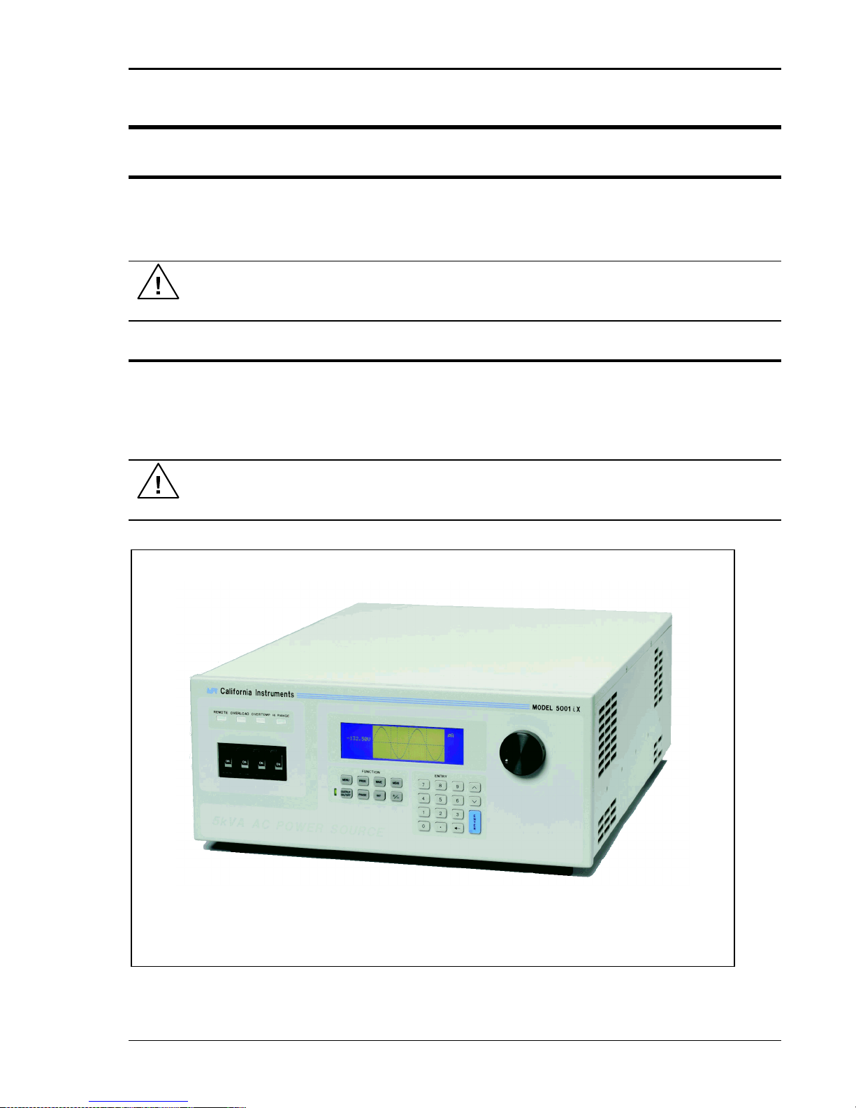
Figure 3-1: The 5001iX Power Source
3. Unpacking and Installation
3.1 Unpacking
Inspect the unit for any possible shipping damage immediately upon receipt. If damage is
evident, notify the carrier. DO NOT return an instrument to the factory without prior approval. Do
not destroy the packing container until the unit has been inspected for damage in shipment.
WARNING: This power source weighs 61 lb (28kg). Obtain adequate help when
moving or mounting the unit.
3.2 Power Requirements
The 3001i/iX AC Power Source has been designed to operate from a single-phase 208 to 240
volt AC line. The 5001i/iX AC Power Source and its systems have been designed to operate
from a three-phase AC line voltage. Three three-phase input models are available for inputs of
208-240 VLL, 400-440 V
(option -400), or 400-480 V
LL
(option -400).
LL
CAUTION: Do not connect 400-480V into the 208-240V unit, the result could be a
severely damaged unit.
i Series / iX Series 15
Page 30

User Manual
3.3 Mechanical Installation
The 3001i/iX and 5001i/iX are completely self contained power sources. They may be used free
standing on a bench top or rack mounted using the optional rack mount/handle kit. The units are
fan cooled, drawing air in from the sides and exhausting at the rear. The sides of each unit must
be kept clear of obstruction and a 6” clearance must be maintained to the rear. Special
consideration of overall air flow characteristics and the resultant internal heat rise must be
allowed for with systems installed inside enclosed cabinets to avoid self heating and over
temperature problems.
3.4 Input Wiring – TB1
The input terminal block, TB1, is located at the rear of the unit. Ground (earth) wire must be
connected to the chassis of the AC power system. The mains source must have a current rating
equal to or greater than the input circuit breaker and the input wiring must be sized to satisfy the
applicable electrical codes. The input terminal block cover and strain relief must be installed in
table top applications to maintain protection against hazardous voltages.
CAUTION: Capacitors in the power source may hold a hazardous electrical charge
even if the power source has been disconnected from the mains supply. Allow
capacitors to discharge to a safe voltage before touching exposed pins of mains
supply connectors.
3.5 Output Power Connections – TB2
The output terminal block, TB2, is located at the rear of the unit. The external sense inputs allow
the power system output voltages to be monitored directly at the load and must be connected
either at TB2 or the load when the sense is programmed for external. The external sense input
does not have to be connected when Internal Sense is programmed. The external sense wires
are to be connected to TB3 on the rear panel and should be run as a twisted pair for short
lengths. Sense leads over three (3) feet long should be run as a twisted shielded pair. Refer to
Figures 3-2 through 3-12 for all connections.
Note: The output of the power source is isolated from the input line and floating from
chassis ground. If needed, either side (HI or LO) may be grounded.
16 i Series / iX Series
Page 31

User Manual
LOAD CURRENT
WIRE GAGE
22 AMPS
10 AWG
37 AMPS
8 AWG
74 AMPS
4 AWG
111 AMPS
2 AWG
The output power cables must be large enough to prevent a total voltage drop exceeding 1% of
the rated output voltage between the power source and the load. Table 3-1 shows the AWG size
of the cables that may be used. Cable lengths must not exceed twenty-five (25) feet. For lengths
greater than 25 feet, calculate the voltage drop from the following formula:
2 X DISTANCE X CABLE RESISTANCE PER FT. X CURRENT = VOLT DROP
Table 3-1: Wire Sizes
i Series / iX Series 17
Page 32

User Manual
J22
Description
1
Analog Common: analog signal common
2
MR B: Phase B master signal
3
Analog Common
4
CS B: Phase B current sum
5
CT Common: Current transformer common
6
OSC B: Phase B oscillator output
7
Analog Common
8
CL B: Phase B current limit reference
9
EXT MOD: External modulation input. A 10 volt input will modulate the output 10%.
Original versions of iX power sources required a 100 volt input to modulate the output by
10%. If you experience problems using the external modulation input, contact California
Instruments customer service.
10
OVR TEMP¯¯¯¯¯¯¯¯¯¯ : A logic low output to indicate an over temperature condition.
11
CNF¯¯¯ : Output relay state: Logic HI = open, LOW = closed.
12
FLT C: Phase C current limit fault control
13
FLT A: Phase A current limit fault control
14
F STB LO: Function Strobe / Trigger output Low signal. This is the emitter lead of an
optically isolated NPN transistor. The internal power controller turns this transistor on to
indicate a change of programmed values. See section 3.6.5 for details.
15
EX SYNC LO: External Sync Low signal. This is the ground return for the TTL external
3.6 Connectors - Rear Panel
A number of connectors are located along the top rear covers. These connectors are in a
recessed area to protect them from shipment damage.
3.6.1 System Interface, Clock and Lock Connectors
WARNING: The system interface connector and Clock and Lock connectors may be at
hazardous voltages. These connections may not be used in table top applications. In
table top applications the safety cover must be in place. These connections may only
be used when the equipment is enclosed in a rack, only within one rack, only with
California Instruments supplied cables, and only between California Instruments
equipment.
J21 and J20 are the Clock and Lock connectors and are used to synchronize and control the
phase shift between the three outputs when 3 units are operating as a three-phase system with
the 15003iX - LK option.
The System Interface connector, J22, is used to connect the slave power sources to the Master
power source (the one with the controller) in multiple box systems. The connector is also used
for the external sync input, external modulation input and trigger output.
Table 3-2: System Interface Connector (J22)
18 i Series / iX Series
Page 33

User Manual
J22
Description
sync input. It connects to the cathode of an LED at the input of an optocoupler. Refer to
J22-32.
16
AMP SHARE B
17
PARALLEL
18
CL ENA
19
MR C: Phase C master signal
20
MR A: Phase A master signal
21
CS C: Phase C current sum
22
CS A: Phase A current sum
23
OSC C: Phase C oscillator output
24
OSC A: Phase A oscillator output
25
CL C: Phase C current limit reference
26
CL A: Phase A current limit reference
27
D COM: Digital Common
28
RNG HI: Voltage range state: Logic HI = high range, LOW = low range
29
: Overload
30
FLT B: Phase B current limit fault control
31
F STB HI: Function Strobe / Trigger output HI. A low-going pulse, >400 s, that indicates
voltage or frequency change. Isolated output that requires a pull-up resistor, 22K , to +5
VDC. Use J22 pin 14 (F STB LO) for common. See section 3.6.5 for details.
32
EX SYNC HI, External Sync input HI. This is an input that can be used to synchronize the
outputs of the AC Power System. This input requires a logic high level of at least +4.5
VDC at 5 mA. The input should have a duty cycle 50 30%. J22-15 is the common input.
The External Sync input is optically isolated. It must be enabled from the SNC screen.
33
AMP SHARE C
34
AMP SHARE A
35
FLICKER /
36
REMOTE ON: This is a logic input that can be used to remove the programmed output
voltage. A logic low on this pin will cause the output voltages to be programmed to 0.0
volts and the output relays to open. A logic high will cause the programmed output
voltage to be restored at the output terminals. A contact closure between this pin and
J22-27 (D COM) will simulate a logic low state.
i Series / iX Series 19
Page 34

User Manual
Pin
Description
A
Phase A sense
B
Phase B sense
C
Phase C sense
N
Neutral sense
3.6.2 Remote Sense Connector TB3
When selecting external sense mode, it is important that the remote sense connections are
hooked up at the EUT or at the sense point. For single-phase systems, connect Phase A to
phase A and neutral to neutral. For three-phase system configurations, connect all three phase.
NOTE: Do not reverse or swap sense connection phasing or damage to the unit may
result.
All 3001iX and 5001iX AC Sources are shipped with the sense connections wired to the output
terminals. This will prevent a voltage fault when the external sense mode is selected. On
systems consisting of multiple 3001iX or 5001iX chassis, the end user has to connect the
external sense inputs to allow the system to operate. Some system configuration do not support
Internal sense mode in which case the sense connection must always be present at TB3.
Table 3-3: Remote Sense Connector – TB3
20 i Series / iX Series
Page 35

User Manual
Pin
1
N/C 2 RxD, Receive data
3
TxD. Transmit data
4
DTR, Data Terminal Ready
5
Common
6
N/C
7
RTS, Request to Send
8
N/C 9 N/C
3.6.3 RS232C Serial Interface Connector – J18
Table 3-4: RS232C Connector
To connect the 5001iX to a PC‟s 9-pin DB9 serial port, a special RS232 cable is required. A 6
foot / 2 meter long cable (CI P/N 7000-263-1) is supplied in the iX Series ship-kit. The wiring
diagram for this cable is shown below in case a longer cable has to be constructed. Alternatively,
a generic straight thru DB9 male to DB9 female cable can be used to extend the supplied cable.
3.6.4 I/O Option – J58
Figure 3-2: RS232C Cable for PC Connection wiring diagram.
This connector is reserved for control of the EOS option. Do not connect anything else to this
connector.
i Series / iX Series 21
Page 36

User Manual
+ 5 Vdc
J22-31
J22-14
Function Strobe
High
Function Strobe
Common
Centronics
Connector
System
Interface
+5
0
> 400 uS
3.6.5 Function Strobe / Trigger Out – J22-31 / J22-14
A function strobe output is available on the System Interface connector. This open collector output
may be used to trigger external equipment when voltage or frequency change occurs on the AC
source.
This output generates a low-going pulse, > 400 s in duration, that indicates voltage or frequency
change. Since this is an isolated output, an external DC supply and pull-up resistor, 22K , 1/8 W is
required. To create a TTL level output, a +5V or +3.3V DC supply is required. To create a signal for
viewing on a scope, a higher DC voltage such as a 9V battery may be used.
Connect the DC supply and pull-up resistor as shown.
Figure 3-3: Function Strobe Connection.
When running list transients on the AC source, the LIST:TTLTrigger SCPI command may be used
reassign the operation of the Function Strobe output as a trigger output. An output pulse is
generated for each logic “1” in the TTLTrigger list. See the iX/i Series Programming Manual P/N
7000-982 for details on the transient list system.
Trigger BNC Breakout Box
A convenient trigger BNC breakout box is available from California Instruments which facilitates
connection to the Function Strobe / Trigger Output signal on the system interface connector. A 9V
DC battery is used to provide the required DC supply. This small box can be ordered through
customer service or sales under P/N 7000-481-1 (for 3001i/iX and 5001i/iX) or P/N 7000-481-2 (for
all multi-chassis i/iX systems).
Figure 3-4: Function Strobe / Trigger Output Accessory.
22 i Series / iX Series
Page 37

User Manual
3.6.6 Remote Inhibit – J22-36 / J22-27
The Remote Inhibit input J22 pin 36 can be used to open and close the output relay of the AC
power source. This input overrides the state of the output relay programmed from the front panel
or the bus. It may be used for safety interlock purposes.
A logic low on this pin will cause the output voltages to be programmed to 0.0 volts and the output
relays to open. A logic high will cause the programmed output voltage to be restored at the output
terminals. A contact closure between pin J22-36 and pin J22-27 (D COM) will simulate a logic low
state.
i Series / iX Series 23
Page 38

User Manual
Figure 3-5: Rear Panel View for the 3001i/3001iX
24 i Series / iX Series
Page 39

User Manual
Figure 3-6: Rear Panel View for the 5001i/5001iX
i Series / iX Series 25
Page 40

User Manual
3.7 Single-Phase and Three Phase Multiple Box System Configurations
Three Phase System:
The three phase system will be configured ready for use when ordered as such from the factory.
One unit, with the controller, will be identified as Phase A on the serial number tag. The other
two units will be identified on their serial number tags as either Phase B or Phase C. The power
sources must be installed in the system according to the phase markings on the serial number
tags. There will be one master unit that will have a full controller and the slaves will have blank
front panels except for the circuit breaker and indicator lights.
The three units must be interconnected using the system Interface cable. The three LO outputs
must also be connected together before applying power.
If the units were purchased as single phase units and have not been configured for a three phase
system please consult the factory.
Single Phase System:
In a single phase system consisting of two or three units there will be one master unit that will
have a full controller and the slaves will have blank front panels except for the circuit breaker and
indicator lights.
The units must all be connected with the system interface cable, but not the clock and lock
cables. The HI outputs on all the terminal blocks should be connected together. The LO
outputs should all be connected together and a heavy duty cable run to the load from the HI and
LO outputs. See Table 3-1 for cable sizing.
The appropriate jumpers have been installed at the factory before shipment. If it becomes
necessary to change the system to three phase output, please consult the factory.
3.8 Output Voltage Ranges
The iX Series power sources have four voltage ranges: 0 to 135, 150, 270 or 300 volts. These
ranges are organized in two pairs: 135/270 and 150/300. When operating on the 135 volt AC
range, the current limit can be programmed to a maximum value of 37 amps for the 5001iX or
22.2 amps for the 3001iX.
The standard power source defaults to the 150/300 range pair. To change voltage range pairs
perform the folowing steps:
1. Press the MENU key 2 times.
2. The cursor should point to UTILITY. Press the ENTER key to display the UTILITY 1 screen.
In the UTILITY 1 screen select VOLT/CURR control by moving the cursor by pressing the
key.
3. Press ENTER.
4. In the VOLT/CURR control screen select VOLT PAIR = . Press the key to change the
range pair to 135/270. Pressing the key again will program the 150/300 range pair.
26 i Series / iX Series
Page 41

User Manual
3.9 Functional Test
CAUTION: Work carefully when performing these tests, hazardous voltages
are present on the input and output during this test.
Refer to Figure 3-8 for the test set up.
1. Connect an oscilloscope, voltmeter and/or distortion analyzer to the AC source output at the
output terminal block (TB2).
2. With the AC mains verified as being off, apply the correct three phase AC power input
voltage connections to the AC source input terminals barrier (TB1). Apply the AC mains
power and turn on the main circuit breaker on the AC source front panel.
3. Verify the front panel LCD display lights up with the initial start up screen showing the unit ID
and serial number. A self check routine screen with follow and finally the system will display
the main “Menu 1” screen with the cursor highlighting the “Program” selection.
4. Press “ENTER” and the unit will display the Program selection screen. Set the following
output parameters: output voltage = 150 volts, frequency = 60 Hz, voltage range = 150 volts,
and current limit = 20.0 amps (3001iX) or 33.3 amps (5001iX). Press “ENTER”.
5. Enable the output by pressing the output “on/off” button below the front panel display screen.
The green LED next to the button will light green when the output is on. The output should
be a clean 150 volt AC sinewave having less than 1% distortion.
6. Apply full load to the output of the source and verify the output remains within 2% of the initial
150 volt value. The output should still be clean and the distortion should still be less than 1%
at 60 Hz.
7. Using the PROGRAM screen set the output current limit value to 17 amps. The system
should go into current limit. Return the current value to 20.0 amps (3001iX) or 33.3 amps
(5001iX) and press the output on/off button to turn the output off. Disconnect the load.
8. Repeat steps 4 through 7 but set the output for the following: output voltage = 300 volts,
output range = 300 volts, current limit = 10.0 amps (3001iX) or 16.7 amps (5001iX). For step
7, the current limit value can be set to 8 amps.
In the unlikely event the power source does not pass the functional test, refer to the
calibration procedure in Section 6 or call California Instrument‟s customer satisfaction
department for further assistance.
i Series / iX Series 27
Page 42

User Manual
Figure 3-7: Connection For Single Power Source (5001iX/i, 3001iX/i)
28 i Series / iX Series
Page 43

User Manual
Figure 3-8: Functional Test Setup
i Series / iX Series 29
Page 44

User Manual
Figure 3-9: Single Phase 10000 VA System (10001iX/i)
30 i Series / iX Series
Page 45

User Manual
Figure 3-10: Three Phase 15000 VA System (15003iX/i-LK Three Controllers)
i Series / iX Series 31
Page 46

User Manual
Figure 3-11: Single Phase 15000 VA System (15001iX/i)
32 i Series / iX Series
Page 47

User Manual
Figure 3-12: Three-Phase 15000 VA system (15003iX/i - One Controller)
i Series / iX Series 33
Page 48

User Manual
Figure 3-13: Connection With MODE Option
34 i Series / iX Series
Page 49

User Manual
Figure 3-14: Two Phase 10000 VA System (10002i-LK Two Controllers)
i Series / iX Series 35
Page 50

User Manual
Figure 3-15: Three-Phase 9000 VA System (9003iX/i – One Controller)
36 i Series / iX Series
Page 51

User Manual
4. Front Panel Operation
4.1 Tour of the Front Panel
The i and iX Series front panels are identical although some of the keys found on the front panel
are only used by iX Series models. If your unit is an i Series, these keys will act as don‟t cares.
This chapter provides information on operating the i and iX Series AC sources from the front
panel keyboard.
Before operating the AC source using the front panel, it helps to understand the operation of the
front panel controls. Specifically, the operation of the knob, keyboard and the menu layout are
covered in the next few paragraphs.
4.1.1 Front Panel Controls and Indicators
The front panel can be divided in a small number of functional areas:
Mains circuit breaker
Status Indicator lights
Shuttle knob
LCD display
FUNCTION keypad
DATA ENTRY keypad
4.1.2 Mains Circuit Breaker
The circuit breaker located on the bottom left side of the front panel disconnects the AC source
from the three phase Line input. It will automatically trip when the input current rating of the unit is
exceeded due to some component failure. The contrasting black color and large size throw bar
make it easy to locate in case of an emergency.
4.1.3 Status Indicator Lights
Four LED status indicators are located directly above the mains circuit breaker. These LED‟s
correspond to the following conditions:
REMOTE The REMOTE LED indicates that the unit is in remote control
mode. If the IEEE-488 interface is used, this indicator will be lit
whenever the REM line (REMOTE ENABLE) line is asserted by
the IEEE controller. If the RS232C interface is used, the
REMOTE state can be enabled by the controller using the
SYST:REM command. Any time the REMOTE LED is lit, the
front panel of the i Series unit is disabled. There is no LOCAL
button that allows the user to regain control of the front panel.
This prevents accidental change of settings in ATE applications.
OVERLOAD The OVERLOAD LED indicates an output overload condition.
i Series / iX Series 37
This condition can be controlled by setting the current limit value
in the PROGRAM menu. Removing the load using the OUTPUT
ON/OFF button will recover from an overload condition.
Page 52

User Manual
Counter
Clock
wise
Clock
wise
INCRDECR
OVER TEMPERATURE The OVER TEMPERATURE LED indicates an overheating
problem inside the unit. This is an abnormal condition, which will
cause the unit to shut off. Check the air openings to make sure
they are not blocked.
HI RANGE The HI RANGE LED is on when the high voltage output range
has been selected.
4.1.4 The Shuttle Knob
The shuttle knob is located to the right of the LCD screen and is used to change setup
parameters. Note that it cannot be used to move the cursor position between menu fields. Use
the UP and DOWN arrow keys in the FUNCTION keypad for this.
The shuttle knob can operate in one of two distinct modes of operation:
MODE DESCRIPTION
IMMEDIATE mode Any time the ENTER key is pressed, the i/iX Series returns to its
SET mode When the SET key located in the FUNCTION keypad is
4.1.5 FUNCTION Keypad
Figure 4-1: Shuttle Knob
normal mode of operation. In this mode, changes made with the
shuttle knob or the data entry keypad will take immediate effect.
The IMMEDIATE mode is useful for slewing output values such
as voltage and frequency and observing the effect on the load.
pressed, changes made with the shuttle to any output parameter
will not take effect until the ENTER key is pressed. In this mode,
any changes made to a setup menu will be blinking to indicate
the pending change condition. This mode allows changes to be
made to all output parameters and executing them all at once by
pressing the ENTER key.
The function keypad provides access to all menus and measurement screens. The following
keys are located in the FUNCTION keypad:
38 i Series / iX Series
Page 53

User Manual
MENU PROG WAVE MEAS
OUTPUT
ON/OFF
PHASE
SET
+/-
FUNCTION
Figure 4-2: FUNCTION keypad
KEY DESCRIPTION
MENU The top level menu is accessed by pressing the MENU key.
Three shortcut keys are used to provide direct access to the
PROGRAM, WAVEFORM, and MEASUREMENT screens as
these are among the most frequently used screens. Thus,
instead of going through the main menu to reach the
PROGRAM, WAVEFORM, and MEASUREMENT screens, they
can be accessed directly by pressing the PROG, WAVE, and
MEAS keys respectively. A map of the Main menus is provided
on the next few pages. There are three top-level menus in the
i/iX Series.
PROG The PROG key is a shortcut to access the PROGRAM menu
WAVE The WAVE key is a shortcut to access the WAVEFORM screen
MEAS The MEAS key is a shortcut to access the MEASUREMENT
OUTPUT ON/OFF The OUTPUT ON/OFF key toggles the output relay on or off.
directly. The PROGRAM menu is one of the most frequently
used menus. Thus, instead of going through the main menu to
reach the PROGRAM menu, it can be accessed directly by
pressing the PROG key.
directly. The WAVEFORM screen is used to select a user
defined arbitrary waveform. (iX Series only)
screen directly. The MEASUREMENT screen is one of the most
frequently used screens. Thus, instead of going through the
main menu to reach the MEASUREMENT screen, it can be
accessed directly by pressing the MEAS key.
The state of the output relay is reflected by the green LED
located directly to the left of the OUTPUT ON/OFF key. If the
green LED is lit, the output relay is enabled (closed) and the
programmed output voltage is present at the output terminals. If
the green LED is off, the output relay is open and both the HIGH
and LO terminal of the output terminal block are disconnected
from the power source. In this mode, the output is floating. The
ON/OFF button provides a convenient way to disconnect the
load without having to remove any wires.
i Series / iX Series 39
Page 54

User Manual
7
ENTRY
E
N
T
E
R
8 9
4 5 6
1 2 3
.0
PHASE The PHASE key is used to select the phase on a three-phase
9003iX or 15003iX unit. Pressing the PHASE key will toggle
phase A, B, C or ABC. Some screens may not support the ABC
or show all phase information in which case this mode is
skipped.
(iX Series with three phase controller only)
SET The SET key is used to select the mode of operation of the
shuttle. Refer to section 4.1.1 for details on its operation and the
use of the SET key.
+/- The +/- key can be used to toggle the sign for those parameters
for which it is relevant. This is typically the output voltage when
in DC mode of operation. For fields that have only two possible
values such as the voltage range field, the +/- key can be used
to toggle between these two values.
4.1.6 DECIMAL KEYPAD
The decimal keypad may be used to enter any numeric parameter required in any of the menu
fields. Several fields accept input from either the keypad or the knob. Data entered from the
keypad is normally accepted once the ENTER key is pressed unless the front panel mode is in
the SET mode. The following keys are available on the decimal keypad:
CURSOR UP The UP key moves the cursor position upwards one position to
40 i Series / iX Series
Figure 4-3: Entering value from decimal keypad
the previous available cursor position. If the present cursor
position is at the top of the right hand column, the cursor is
moved to the bottom position of the left hand column. If the
present cursor is at the top of the left hand column, the cursor is
moved to the bottom of the right hand column. Figure 4-4
depicts the cursor movement through a two-column menu.
Page 55

User Manual
Figure 4-4: Cursor UP key movement
CURSOR DOWN The DOWN key moves the cursor position downwards one
position to the next available cursor position. If the present
cursor position is at the bottom of the left hand column, the
cursor is moved to the top position of the right hand column. If
the present cursor is at the bottom of the right hand column, the
cursor is moved to the top of the left hand column. Figure 4-5
depicts the cursor movement through a two column menu.
Figure 4-5: Cursor DOWN key movement
The decimal keypad can be used at any time in lieu of the shuttle knob to change output
parameters. Direct data entry is often faster to effect large changes in values than using the
shuttle knob. Note that pressing the ENTER key while in SET mode of operation will cause the
AC source to revert back to IMMEDIATE mode. Thus, to change all parameters in SET mode,
enter a value for each field and then proceed to the next field without pressing the ENTER key.
0 through 9 The numeric keys provide all decimal number for entry of
DECIMAL POINT The decimal point key is used to enter fractional parts of values
BACKSPACE The BACKSPACE ( ) key can be used to erase one digit at a
4.1.7 LCD Display
The LCD display of the i and iX Series AC power source provides information on instrument
settings and also guides the user through the various menus. To ease reading of the displayed
information, most screens are widely spaced. A sample of the main menu 1 screen that appears
when the i Series AC source is powered up is shown in Figure 4-6. Due to the amount of space
available on each screen, some menus have been split into parts. The MORE selection located
at the bottom right hand side provides access to menu choices at the same level that did not fit
on a single screen. Thus, to access MENU 2, the cursor should be placed on the „MORE‟
selection followed by pressing the „ENTER‟ key. Alternatively, the MENU key may be pressed to
move to the MENU 2 screen.
parameters.
for fields that have a resolution less than 1. The amount of
resolution for each menu field is normally visible on the LCD. If
more digits are entered after the decimal point than can be
accepted by a field, the value is automatically rounded to the
available resolution when the ENTER key is pressed.
time if you make a data entry error.
The present cursor position is always shown with a inverse bar. The cursor is located on the
„MORE‟ selection in Figure 4-6. Pressing ENTER would cause MENU 2 to be displayed.
i Series / iX Series 41
Page 56

User Manual
The cursor position can be moved by using the UP and DOWN keys located in the DECIMAL
keypad.
Figure 4-6: Main Menu 1 screen
4.2 Menu Structure
The next few pages show a map of the available menus in the i/iX Series. There are three main
level (level 1) menus from which all other menus can be reached. Frequently used (level 2)
menus have a short cut key that provides direct access. Examples of such menus are Program,
Measurements, and Waveform. In any case, there are never more than three levels of menus
although some menus may be spread across more than one screen.
4.2.1 MAIN Menus
Figure 4-7: Menu 1 through 3
The top level menu is split in three parts, MENU 1 through MENU 3 to allow spacing between
menu entries. MENU 2 and 3 can be reached from MENU 1 by selecting the MORE entry or by
pressing the MENU key repeatedly, which will toggle from MENU 1 to 2 to 3 and back to 1. The
division of menu choices between the two screens is graphically illustrated in 4.2.2 by the boxes
in level 1. Each box represents one screen. Subsequent screens can be reached using the
MORE entry.
42 i Series / iX Series
Page 57

User Manual
The following top-level menu choices can be accessed from the MENU key:
Entry Description
PROGRAM The PROGRAM menu allows output parameters the be
changed.
MEASUREMENTS The MEASUREMENTS screens are not menus in that no user
entries are required.
TRANSIENTS The TRANSIENTS menu allows output transients to be
programmed.
WAVEFORMS The WAVEFORMS menu allows different waveforms to be
selected from the waveform library.
MORE The MORE selection causes the second part of the MENU
screen to be displayed. (MENU 2)
ADVANCED MEAS. The ADVANCED MEAS. screens are for display only. No user
entries are required.
MENU 1
MENU 2
APPLICATIONS The APPLICATIONS menu provides access to the optional
firmware application programs that may be installed in the i/iX
Series AC source.
SETUP REGISTERS The SETUP REGISTERS menu allows complete instrument
settings and transient list programs to be saved to nonvolatile
memory.
MORE The MORE selection causes the third part of the MENU screen
to be displayed. (MENU 3)
MENU 3
UTILITY The UTILITY menu provides access to less commonly used
setup screens such as those for the GPIB and RS232C
interface settings, initial startup values, etc.
OUTPUT IMPEDANCE The OUTPUT IMPEDANCE menu provides control of the AC
source output impedance. (Available only on 3001iX, 5001iX,
9003iX and 15003iX models. On systems with –MODE-iX
option, only available when in 3 phase mode.)
MEASUREMENT CAL The MEASUREMENT CAL menu allows for calibration of the
AC source measurement system.
OUTPUT CAL The OUTPUT CAL menu allows for calibration of the AC source
output.
Following the Menu overview pages is a detailed description of each menu and sub menu.
i Series / iX Series 43
Page 58

User Manual
level 1
level 2 level 3
MENU 1
PROGRAM PROGRAM1
VOLTAGE
FREQ
VOLT RANGE
CURR LIMIT
MORE
PROGRAM2
PHASE
CLOCK MODE
VOLT MODE
DC OFFSET
START ø
MEASUREMENTS
MEASUREMENTS1
VOLTAGE
CURRENT
FREQ
POWER
MORE
MEASUREMENTS 2
VA POWER
PEAK CURR
POWER FACT
CREST FACT
PEAK CURR RESET
MEASUREMENTS 3
VOLT THD
CURR THD
INST PK CURR
PHASE
HARMONICS/TRACE
ANALYSIS
FUNCTION
VIEW
DATA MODE
SCALE
TRIG MODE
TRIG SOURCE
TRIG PHASE
TRIG DELAY
START
TRANSIENTS
VOLT SURGE/SAG
START ø
VOLT SWEEP/STEP
START ø
GO TO VOLT
FREQ SWEEP/STEP
DURATION
END VOLT
DUR SCALE
VOLT/FREQ SWEEP/STEP
DURATION
END FREQ
DUR SCALE
DURATION
START/VIEW SEQUENCE
START
END VOLT
END DELAY
DURATION
END VOLT
PREVIOUS SCREEN
PAUSE
END FREQ
FUNCTION
END DELAY
END DELAY
REPEAT #0
END DELAY
REPEAT
FUNCTION
FUNCTION
CLEAR SEQ
FUNCTION
EVENT#
REPEAT
REPEAT
REPEAT
PREVIOUS SCREEN
EVENT#
EVENT#
#1
SEQUENCE#
PREVIOUS SCREEN
PREV. SCREEN
#2
PREVIOUS SCREEN
..
#98
#99
PREVIOUS SCREEN
WAVEFORMS
CLIP LEVEL
GROUP
MODE
SINE
SQUARE
CLIPPED
USER WAVE
..
..
MORE
USER WAVE
4.2.2 Overview of Menu 1
44 i Series / iX Series
Page 59

User Manual
level 1
level 2 level 3
MENU 2
ADVANCE
HARMONICS/TRACE
MEAS. ANALYSIS
FUNCTION
VIEW
DATA MODE
SCALE
TRIG MODE
TRIG SOURCE
TRIG PHASE
TRIG DELAY
START
APPLICATIONS
MIL-STD 704D
STEADY STATE
OMNI OPTION
MODE
TRANSIENTS
RTCA-DO160C
NORMAL STATE
PREVIOUS SCREEN
ABNORMAL
IEC 1000-4-11
VOLTAGE DIPS
EMERGENCY
EMERGENCY
PREVIOUS SCREEN
VOLT VARIATIONS
ABNORMAL
ALL MIL704 TESTS
INRUSH CURRENT
PREVIOUS SCREEN
PREVIOUS SCREEN
PREVIOUS SCREEN
SETUP
SAVE REGISTER #
REGISTERS
VIEW/EDIT REG #
RECALL REGISTER #
PREVIOUS SCREEN
MORE
MENU 3
UTILITY UTILITY 1
GPIB/RS232 SETUP
GPIB ADDRESS
VOLT/CURR CONTROL
VOLT PAIR
RS232 BAUDRATE
PREVIOUS SCREEN
OL MODE
RS232 DATA
INITIAL SETUP
VOLTAGE
TRIP DELAY
RS232 PARITY
LIMIT SETUP
VOLTAGE
CUR LIMIT
VOLT SENSE
RS232 STOPBITS
MORE
CUR LIMIT
PREV. SCREEN
NO. OUTPUT
PREVIOUS SCREEN
UTILITY 2
FREQ LO
FREQ
PREV. SCREEN
CONFIGURATION
NO. OUTPUT
FREQ HI
PHASE
ELAPSED TIME
CLOCK/LOCK
PHASE C
MORE
VIEWING ANGLE
PREVIOUS SCREEN
PREVIOUS SCREEN
VOLT RANGE
PREVIOUS SCREEN
DO160C
VOLT MODE
MIL704
OL MODE
IEC1000-4-11
OUTPUT RELAY
MORE
HH:MM:SS
VOLT SENSE
TEMPERATURE
WAVE GROUP
CLOCK MODE
OUTPUT
RESISTIVE
NO. OUTPUT
IMPEDANCE
INDUCTIVE
PREVIOUS SCREEN
FLICKER
MINIMUM
MEASUREMENT
VOLT FS
CAL
VOLT 0
VOLT FS HT
VOLT FS 0
CURR FS
CURR 0
CURR FS HT
CURR 0 HT
PREVIOUS SCREEN
OUTPUT CAL
VOLT FS
V HI-FREQ
VOLT ZERO
PHASE OFST
IMP. REAL FS
IMP. REACT FS
IMP. REAL MIN
IMP. REACT MIN
PREVIOUS SCREEN
4.2.3 Overview of Menu 2 and 3
i Series / iX Series 45
Page 60

User Manual
4.2.4 PROGRAM Menu
Figure 4-8: PROGRAM Menu
The PROGRAM menu is shown in Figure 4-8. It can be reached in one of two ways:
1. by selecting the PROGRAM entry in the MENU screen and pressing the ENTER key
2. by pressing the PROG key in the FUNCTION keypad
The PROGRAM menu is used to change output parameters. The most commonly used
parameters are all located in PROGRAM 1. The PREVIOUS SCREEN entry, when selected, will
return the user to the most recently selected menu. This is normally the MENU screen unless the
PROGRAM menu was selected using the PROG key on the FUNCTION keypad. Less frequently
used parameters are located in PROGRAM 2 which can be reached from the PROGRAM 1
screen using the MORE selection, or by pressing the PROGRAM key twice.
The following choices are available in the PROGRAM menus:
Entry Description
PROGRAM 1
VOLTAGE Programs the output voltage in rms. when in AC mode or
absolute voltage when in DC mode. In DC mode, negative
values can be entered.
FREQ Programs the output frequency when in AC mode. If the unit is
in DC mode, the value for FREQ will be set to DC and cannot be
changed until AC mode is selected. When in AC mode, the
frequency can be changed from 16 Hz to 500 Hz. Values
entered that fall outside this range will generate a -200 RANGE
ERROR and will not be accepted.
VOLT RANGE Selects 135/150V or 270/300V voltage range. The actual range
values may be different depending on the configuration. The
value of this field can only be changed with the shuttle or the +/key.
Note that the voltage range is coupled with the output relay
state on all i/iX AC sources with firmware revision 2.39 or
higher. If the output relay is closed (OUTPUT ON), the voltage
range cannot be changed.
CURR LIMIT Sets the current limit value for the current detection system.
When the load current value exceeds the set current limit, a
fault condition is generated. The actual response of the AC
Source to a current limit fault is determined by the protection
mode selected in the CONFIGURATION menu. (CC = Constant
Current, CV = Constant Voltage).
46 i Series / iX Series
Page 61

User Manual
PHASE Selects the phase angle between the external clock and the
output of the AC source. If the clock source is internal, this
parameter has no effect.
CLOCK MODE Selects internal or external clock source. The i/iX Series uses
an open air crystal timebase with an accuracy of 100 ppm. To
improve output frequency stability and accuracy, an external
clock generator may be used.
VOLT MODE The iX Series offers three output modes, AC, DC and AC+DC.
The VOLT MODE field can be used to toggle between these
three output modes. Both the Knob and the +/- key may be used
to toggle through these three selections. In DC mode, no
frequency selection is possible and all maximum current and
power ratings are divided by two. The i Series offers AC or DC
modes.
DC OFFSET When the AC+DC mode is selected, the VOLTAGE field in the
PROGRAM 1 screen is used to set the AC portion of the output
voltage. The DC OFFSET field in the PROGRAM 2 screen can
be used to set the DC offset level. Either the knob or the
decimal keypad may be used to set the DC offset level.
PROGRAM 2
STARTø Selects the start phase angle for output changes made to either
voltage or frequency. This allows changing the output at a
specific phase angle. The output on key also uses this phase
angle setting to program the output voltage up to the set level
after the output relay is closed. The default value for this field is
RANDOM.
i Series / iX Series 47
Page 62

User Manual
4.2.5 MEASUREMENTS Screens
The i/iX Series uses a DSP based data acquisition system to provide extensive information
regarding the output of the Source. This data acquisition system digitizes the voltage and current
waveforms and calculates several parameters from this digitized data. The result of these
calcalutions is displayed in a series of measurement data screens. The actual digitized
waveforms can also be displayed by selecting the Harmonics/Trace Analysis screen. A total of
four measurement screens are used to display all this information (iX series only).
Figure 4-9: MEASUREMENTS Screen, single phase and three phase modes
The first three Measurement screens available on the iX Series are not menus in that no
changes can be made anywhere. Instead, these three screens provide load parameter readouts.
The fourth measurement screen provides access to the advanced measurements and does offer
several user accessible fields (iX Series only). The measurement screens can be reached by
successively pressing the MEAS key which will toggle to all four available screens.
In three phase configuration iX Series, measurements are available for each phase individually.
To select the desired phase, use the PHASE key to toggle through phase A,B,C, or ABC. The
ABC mode displays the data for all three phases simultaneously.
The following parameters are available in the first three measurement screens:
Entry Description
MEASUREMENT 1
VOLTAGE When in AC or AC+DC mode, this value is the true rms output
voltage measured at the voltage sense lines. In DC only mode,
the voltage is the DC voltage including polarity.
CURRENT When in AC or AC+DC mode, this value is the true rms output
current drawn by the load. In DC only mode, the current is the
DC current including polarity
FREQ When in AC or AC+DC mode, the output frequency is measured
at the sense lines. When in DC only mode, this value always
reads “DC”.
POWER In both AC and DC mode, this value is the real rms. power
consumed by the load.
MEASUREMENT 2
VA POWER In AC or AC+DC mode, this value is the apparent rms. power
consumed by the load. In DC mode, this value is always the
same as the POWER readout.
48 i Series / iX Series
Page 63

User Manual
PEAK CURR This readout reflects the peak current value detected at the
output. To measure inrush current for a unit under test, open the
output relay and reset the peak current value using the PEAK
CURR RESET entry. Then program the output voltage and
frequency and turn on the output relay. The peak current
measurement will continuously track the maximum current value
detected until reset.
POWER FACTOR This readout shows the power factor of the load.
CREST FACTOR This readout displays the ratio between peak current and rms
current.
VOLT THD This readout displays the total voltage distortion for the selected
phase.
CURR THD This readout displays the total current distortion for the selected
phase.
INST PK CURR This readout reflects the instantaneous peak current value
detected at the output. This value is updated continuously and
does not require a reset operation like the PEAK CURR readout.
The instantaneous peak current does not use a track and hold
mechanism like the PEAK CURR measurement in the
MEASUREMENT 2 screen. Instead, it tracks the peak current
on a cycle by cycle basis. The INST PK CURR typically tracks
the rms current and the crest factor.
MEASUREMENT 3 [iX Series only]
Update Program Functions from Measurement Screen
The Shuttle can be used to update program parameters such as voltage, frequency or current
from the measurement screen. This can be achieved with the following sequence:
1. Select the program 1 screen using the PROG key.
2. Use the up and down key to select the desired function to update. (Selects parameter that
will be changed by the shuttle once in the MEAS1 screen)
3. Select the measurement 1 screen by pressing the MEAS key.
4. The pointer symbol ( ) points to the programmed parameter (V,F or CL) that will be
affected by turning the shuttle.
i Series / iX Series 49
Page 64

User Manual
TABLE mode:
displays the first 50 harmonics in a
tabular text format.
BAR mode:
displays the first 50 harmonics in a
graphical bar chart display.
TRACE mode:
displays the selected Function in a
time domain (waveform) graphical
display.
HARMONICS/TRACE ANALYSIS Screen [iX Series only]
The fourth measurement screen is dedicated to the advanced measurements available on the iX
Series only. This screen is not available on the i Series. The Harmonics/Trace Analysis
measurement screen is a true menu screen offering several user accessible fields. These fields
are used to select the desired acquisition trigger and display mode. The actual data is displayed
whenever the ENTER key is pressed while the cursor is on the VIEW or START field. The
following fields are available on this menu:
Figure 4-10: HARMONICS/TRACE ANALYSIS screen
Entry Description
FUNCTION Selects Voltage, Current or Both parameters for display.
VIEW Available display modes are TABLE, BAR and TRACE.
50 i Series / iX Series
Page 65

User Manual
DATA MODE Selects absolute or relative harmonics display for TABLE and
BAR view modes. In relative mode, all harmonics are shown in a
percentage of the fundamental which is normalized at 100 %. In
absolute mode, the harmonic amplitudes are shown in absolute
volts or amperes.
This mode does not apply to the TRACE view display mode and
is ignored when this mode is selected.
SCALE Sets the horizontal time axis for the TRACE view display mode.
The field can range from 4 ms to 104 ms in single phase mode
or 12 ms to 312 ms in three phase mode.
This parameter is ignored when the TABLE or BAR view display
mode is selected.
TRIG MODE This field sets the trigger mode for the acquisition. Available
options are SINGLE (single shot acquisition) or CONT
(continuous acquisition). In SINGLE shot mode, the acquisition
is triggered once each time the START field is selected and the
ENTER key is pressed. The selected trigger source is used to
determine the trigger point. Once the acquisition has been
triggered, the data are displayed and do not change until the
next acquisition is triggered. This mode is most appropriate for
single shot events such as start up currents.
In the CONT mode, acquisitions occur repeatedly and the data
is updated on screen after each trigger occurs. This provides a
continuous update of the data and is most appropriate for
repetitive signals.
TRIG SOURCE The trigger source selects the event that will trigger a
measurement acquisition. Available options for this field are
IMM (immediate), PHASE A or SET VOLT. The IMM trigger
source causes the acquisition to trigger immediately when the
ENTER key is pressed on the START field. Essentially, this is
an asynchronous trigger event. The acquisition will always be
triggered in this mode and data is available immediately.
The PHASE A source will cause the acquisition to trigger on the
occurrence of a set phase angle for the voltage on phase A. The
trigger source is always phase A when in this mode, regardless
of the phase selection shown in the top right corner of the
display. When the acquisition is started, the acquisition system
waits for the specified phase angle to occur before triggering the
acquisition. This mode allows exact positioning of the acquisition
data window with respect to the voltage waveform.
The SET VOLT mode causes the acquisition to trigger at the
specified voltage. This mode also programs the selected phase
or all three phases when the measurement is started from the
START field. As such, this trigger source selection also
programs the output voltage to the selected rms level.
TRIG PHASE / SET VOLT This field changes purpose, depending on the trigger source
i Series / iX Series 51
selected immediately above it. If the trigger source equals IMM
or PHASE A, this field can be used to program the trigger phase
angle (TRIG PHASE). In IMM mode, the value of this field is
ignored.
Page 66

User Manual
If the trigger source is set to SET VOLT, this field can be used
to specify the rms voltage to program the output to and trigger
the measurement on. The voltage value set here should not
exceed the maximum voltage range selected or the rms
capability for the waveshape selected on the phase or phases
programmed.
TRIG DELAY The trigger delay field allows the trigger point to be positioned
anywhere in the acquisition window. A negative value will
provide pre-trigger information on data leading up to the trigger
event. The pre-trigger delay can not exceed the length of the
acquisition buffer (104 ms in single phase mode, 312 ms in
three phase mode). A positive trigger delay positions the data
window after the trigger event. Positive trigger delays can
exceed the length of the acquisition buffer in which case the
trigger event itself will not be in the buffer any more. The
maximum value of the trigger delay is 1000 ms. The default
trigger delay value is 0.0 ms which puts the trigger event at the
beginning of the acquisition window.
START The START field is used to start a new acquisition run. To start
an acquisition, place the cursor on the START field and press
the ENTER key. Once the ENTER key is pressed, the display
toggles to the data display mode selected in the VIEW field as
soon as the selected trigger event occurs. To return to the
HARMONICS/TRACE ANALYSIS menu, press the ENTER key
while in the data display mode.
To change display modes without triggering a new acquisition,
make the desired changes in the menu and move the cursor to
the VIEW field. Once on the VIEW field, press the ENTER key.
This will not trigger a new acquisition which means the original
data is retained.
52 i Series / iX Series
Page 67

User Manual
4.2.6 TRANSIENTS Menu
Figure 4-11: TRANSIENTS menu
The transient menu provides access to the transient list data. Both the i and the iX Series have a
transient list of up to 32 data points. This is represented by 32 transient step numbers from 1
through 32. From the Transient menu, the desired transient step type can be selected. Based on
the user‟s choice, the relevant transient type sub menu will be shown. The START/EDIT
SEQUENCE sub menu allows the user to review and change any transient step or execute the
transient list. When executing a transient list, transient steps are executed in a ascending
numerical order. Steps that are not defined are skipped.
The following entries can be found in the TRANSIENTS menu:
Entry Description
VOLT SURGE/SAG Voltage surges and sags are temporary changes in amplitude.
The output voltage will change from its present value to a user
specified value for a specified duration. (Sag if the value is
lower, surge if the value is higher.) After this period has expired,
the output voltage returns to a user specified end value. This
value may or may not be the same as the value present prior to
the start of the sag or surge.
VOLT SWEEP/STEP Voltage sweeps cause the output voltage to change from the
present value to a user specified end value at a specified rate of
change. A voltage step on the other hand is an instantaneous
change in output voltage. The new value will be held for the
duration period specified by the user. The final output voltage
value of a sweep and a step transient step should be different
than the value at the start of the transient step or no change in
output value will occur.
FREQ SWEEP/STEP This transient type is similar to a voltage sweep/step except it
affects the frequency. Refer to the previous paragraph.
VOLT/FREQ SWEEP/STEP This transient type combines the previous two types into a single
step. The effect is that of changing the output voltage and
frequency simultaneously.
Note: While this transient is programmed as a single transient
step, two list entries are required to store this information. As
such, every VOLT/FREQ SWEEP/STEP used will consume two
list entries at a time.
START/VIEW SEQUENCE This entry allows the user to switch to the transient execution
menu. This menu provides a list of all available transient list
steps and their sequence numbers. From this menu, transient
list execution can be started.
The same menu can be used to view or edit any available
transient list step or erase a step using the backspace key.
i Series / iX Series 53
Page 68

User Manual
4.2.6.1 VOLT SURGE/SAG sub menu
Figure 4-12: VOLTAGE SURGE/SAG SETUP screen
The Voltage surge and sag screen shown in Figure 4-12 can be reached from the transient
screen as follows:
1. Scroll to the VOLT SURGE/SAG entry using the up and down cursor keys.
2. Press the ENTER key to bring up the VOLT SURGE/SAG screen.
The VOLT SURGE/SAG screen has several data fields. All data fields that are blank to the right
of the equal sign must be filled or an error message will occur when trying to leave this screen.
The EVENT # is the last data field to be filled. Entering the event data field will cause the display
to return to the TRANSIENT screen where a new selection can be made.
The VOLT/SURGE/SAG screen has the following fields:
START ø This field will show the start phase angle of the voltage transient
in degrees. Only one start phase angle per transient sequence
is allowed. The start phase angle must be in the first transient
event in the list. The start phase angle is not valid for DC
transients. If no start phase angle is required, this field can be
set to RANDOM by pressing the BACKSPACE (<-) key on the
decimal keypad.
GO TO VOLT This field will set the voltage level during the transient duration in
volts
DUR SCALE Duration scale default is time in seconds. Use the Shuttle knob
to select CYCLES if desired. Note that durations expressed in
cycles may cause rounding errors if the period of the selected
frequency setting is not an integer number of mss. Thus, for 50
Hz applications, no rounding errors occur but for 60 Hz, the
16.66¯ ms period will cause a rounding error when converted.
The Duration scale selection affects both the DURATION and
END DELAY parameters.
DURATION Duration is the time the output voltage level will dwell at the GO
TO VOLT level. The DUR SCALE defines the time scale of this
parameter in CYCLES or SECONDS
END VOLT This is the output voltage level at the end of the transient
EVENT and after a time specified by the DURATION
END DELAY This is the time delay the voltage level will stay at the END
VOLT level before it proceeds with the next transient event or
completes the transient.
FUNCTION [iX Series only] This field can be used to select the waveshape
to be used during this step of the transient sequence. Each step
can use a different waveshape from the available library of 50
user defined waveforms or the three standard waveforms. The
output waveshape changes upon entry into each step and
remains in effect for the duration of the step. The default
waveshape is always the SINE (sinewave).
54 i Series / iX Series
Page 69

User Manual
REPEAT This is the number of times the SURGE/SAG transient event will
repeat before it will proceed to the next event or exit the
transient program. Note that the number of times the transient
event is generated is equal to the REPEAT + 1. Leave this value
at zero if only one execution of this event in the list is required.
EVENT # This must be the last item in the transient edit screen. All data
fields must be entered before inserting the EVENT #. The
EVENT # takes a value from 1 to 99. The EVENT # defines the
order of execution of the transient events in a multiple event
transient. It is a good practice to enter spaced EVENT #‟s to
allow insertion of an EVENT later if needed. (For example,
space them by 5.) Entry of a sequence EVENT # number will
cause the display to return to the TRANSIENT screen.
i Series / iX Series 55
Page 70

User Manual
4.2.6.2 VOLTAGE SWEEP/STEP sub menu
Figure 4-13: VOLTAGE SWEEP/STEP SETUP screen
The Voltage sweep and step screen shown in Figure 4-13 can be reached from the transient
screen as follows:
1. Scroll to the VOLT SWEEP/STEP entry using the up and down keys.
2. Press the ENTER key to bring up the VOLTAGE SWEEP/STEP screen.
The VOLTAGE SWEEP/STEP screen has several data fields. All data fields that are blank to the
right of the equal sign must be filled or an error message will occur when trying to leave this
screen. The EVENT # is the last data field to be filled. Entering the event data field will cause the
display to return to the TRANSIENT screen where a new selection can be made.
The VOLTAGE SWEEP/STEP screen has the following fields:
START This field will show the start phase angle of the voltage transient
in degrees. Only one start phase angle per transient sequence
is allowed. The start phase angle must be in the first transient
event in the list. The start phase angle is not valid for DC
transient.
END VOLT This is the output voltage level at the end of the transient event
in volts.
DUR SCALE Duration scale default is time in seconds. Use the Shuttle knob
to select CYCLES if desired. Note that durations expressed in
cycles may cause rounding errors if the period of the selected
frequency setting is not an integer number of mss. Thus, for 50
Hz applications, no rounding errors occur but for 60 Hz, the
16.66¯ ms period will cause a rounding error when converted.
The Duration scale selection affects both the DURATION and
END DELAY parameters.
DURATION Duration is the time it will take for the output voltage to reach the
END VOLT level. As such, “Duration” will define the slew rate of
the output voltage for the event. A duration of 0 seconds will
cause the output voltage to reach the end voltage immediately.
The DUR SCALE defines the time parameter CYCLES or
SECONDS
END DELAY This is the time delay the voltage level will stay at END VOLT
before it proceeds with the next transient event or completes the
transient.
FUNCTION [iX Series only] This field can be used to select the waveshape
56 i Series / iX Series
to be used during this step of the transient sequence. Each step
can use a different waveshape from the available library of 50
user defined waveforms or the three standard waveforms. The
output waveshape changes upon entry into each step and
remains in effect for the duration of the step. The default
waveshape is always the SINE (sinewave).
Page 71

User Manual
REPEAT This is the number of times the VOLTAGE SWEEP/STEP
transient event will repeat before it will proceed to the next event
or exit the transient program. Note that the number of times the
transient event is generated is equal to the REPEAT + 1. Leave
this value at zero if only one execution of this event in the list is
required.
EVENT # This must be the last item in the transient edit screen. All data
fields must be entered before inserting the EVENT #. The
EVENT # takes a value from 1 to 99. The EVENT # defines the
order of execution of the transient events in a multiple event
transient. It is a good practice to enter spaced EVENT #‟s to
allow insertion of an EVENT later if needed. (For example,
space them by 5.) Entry of a sequence EVENT # number will
cause the display to return to the TRANSIENT screen.
i Series / iX Series 57
Page 72

User Manual
4.2.6.3 FREQUENCY SWEEP/STEP sub menu
Figure 4-14: FREQUENCY SWEEP/STEP SETUP screen
The Voltage sweep and step screen shown in Figure 4-14 can be reached from the transient
screen as follows:
1. Scroll to the FREQ SWEEP/STEP entry using the up and down cursor keys.
2. Press the ENTER key to bring up the FREQ SWEEP/STEP screen.
The FREQ SWEEP/STEP screen has several data fields. All data fields that are blank to the right
of the equal sign must be filled or an error message will occur when trying to leave this screen.
The EVENT # is the last data field to be filled. Entering the event data field will cause the display
to return to the TRANSIENT screen where a new selection can be made.
The FREQ SWEEP/STEP screen has the following fields:
DURATION Duration is amount of the time the output frequency will take to
reach the END FREQ level. Duration will define the slew rate of
the output frequency for the event. A duration of 0 seconds will
cause the output frequency to reach the end frequency
immediately.
END FREQ This is the output frequency at the end of the transient event in
Hz.
END DELAY This is the time delay the frequency will stay at END FREQ
before it proceeds with the next transient event or completes the
transient.
FUNCTION [iX Series only] This field can be used to select the waveshape
to be used during this step of the transient sequence. Each step
can use a different waveshape from the available library of 50
user defined waveforms or the three standard waveforms. The
output waveshape changes upon entry into each step and
remains in effect for the duration of the step. The default
waveshape is always the SINE (sinewave).
REPEAT This is the number of times the FREQUENCY SWEEP/STEP
transient will repeat before it will proceed to the next event or
exit the transient. The number of times the transient event is
generated is equal to the REPEAT + 1. Leave this value at zero
if only one execution of this event in the list is required.
EVENT # This must be the last item in the transient edit screen. All data
fields must be entered before inserting the EVENT #. The
EVENT # takes value from 1 to 99. The EVENT # defines the
order of execution of the transient events in a multiple event
transient. It is a good practice to enter spaced EVENT #‟s to
allow insertion of an EVENT later if needed. (For example,
space them by 5.) Entry of a sequence EVENT # number will
cause the display to return to the TRANSIENT screen.
58 i Series / iX Series
Page 73

User Manual
4.2.6.4 VOLTAGE/FREQUENCY SWEEP/STEP sub menu
Figure 4-15: VOLTAGE/FREQUENCY SWEEP/STEP SETUP screen
The Volt/freq sweep/step screen shown in Figure 4-15 can be reached from the transient screen
as follows:
1. Scroll to the VOLT/FREQ SWEEP/STEP entry using the up and down cursor keys.
2. Press the ENTER key to bring up the VOLT/FREQ SWEEP/STEP screen.
The VOLT/FREQ SWEEP/STEP screen has several data fields. All data fields that are blank to
the right of the equal sign must be filled or an error message will occur when trying to leave this
screen. The EVENT # is the last data field to be filled. Entering the event data field will cause the
display to return to the TRANSIENT screen where a new selection can be made.
The VOLT/FREQ SWEEP/STEP screen has the following fields:
DURATION Duration is the amount of time the output voltage and frequency
will take to reach the END FREQ and END VOLT levels.
Duration will define the slew rate of the output voltage and
frequency for the event. A duration of 0 seconds will cause the
output voltage and frequency to reach their end value
immediately.
END FREQ This is the output frequency at the end of the transient event in
Hz.
END VOLT This is the output voltage at the end of the transient event in
volts.
END DELAY This is the time delay the output frequency and voltage will stay
at END FREQ and END VOLT before proceeding with the next
transient event or completing the transient.
FUNCTION [iX Series only] This field can be used to select the waveshape
to be used during this step of the transient sequence. Each step
can use a different waveshape from the available library of 50
user defined waveforms or the three standard waveforms. The
output waveshape changes upon entry into each step and
remains in effect for the duration of the step. The default
waveshape is always the SINE (sinewave).
REPEAT This is the number of times the VOLTAGE/FREQUENCY
SWEEP/STEP transient will repeat before it will proceed to the
next event or exit the transient. The number of times the
transient event is generated is equal to the REPEAT + 1. Leave
this value at zero if only one execution of this event in the list is
required.
i Series / iX Series 59
Page 74

User Manual
EVENT # This must be the last item in the transient edit screen. All data
fields must be entered before inserting the EVENT #. The
EVENT # takes value from 1 to 99. The EVENT # defines the
order of execution of the transient events in a multiple event
transient. It is a good practice to enter spaced EVENT #‟s to
allow insertion of an EVENT later if needed. (For example,
space them by 5.) Entry of a sequence EVENT # number will
cause the display to return to the TRANSIENT screen.
4.2.6.5 START/VIEW TRANSIENT SEQUENCE sub menu
Figure 4-16: START/VIEW TRANSIENT SEQUENCE screen
The START/VIEW TRANSIENT SEQUENCE screen is used to control transient execution. It
also provides an overview of available transient list events. This list appears in the order they
were assigned event numbers. Editing an existing event can be accomplished from this screen
by positioning the cursor on the event to be edited and pressing the ENTER key. This method
can also be used to review the parameters of a previously entered event.
The START/VIEW TRANSIENT SEQUENCE screen has the following fields:
START / ABORT The START field is used to start a transient execution. When
the cursor is positioned on the START field and the ENTER key
is pressed, transient execution starts. The output relay must be
closed or an error message will appear and the transient will not
start.
Once a transient is in progress, this field changes to ABORT
and can be used to abort a transient in progress. If the transient
completes execution, the field reverts back to START.
PAUSE / RESUME The PAUSE field may be used to suspend execution of a
transient list in progress. If the cursor is on the PAUSE field and
the ENTER key is pressed, the transient is suspended and this
field changes to RESUME. Pressing the ENTER key again will
cause the transient list to resume execution from the point
where it was suspended.
REPEAT # This field determines the number of times a transient list is
repeated. The default value is zero which means the
programmed list runs only once. The range for this field is from
0 through 99999. This repeat function should not be confused
with the REPEAT function available for individual events. The
event specific repeat value will cause only that event to be
repeated, not the entire list.
CLEAR SEQ Moving the cursor to this field and pressing the ENTER key will
cause the entire programmed transient list to be erased. Be
careful not to press ENTER accidentally while on this field as
you will loose the programmed transient list. Note that a list may
be stored as part of the front panel setup in the nonvolatile
memory registers.
60 i Series / iX Series
Page 75

User Manual
4.2.7 WAVEFORMS Menu [iX Series only]
Figure 4-17: WAVEFORMS menu
The WAVEFORMS menu is available on the iX Series only. If your unit is an i Series, pressing
the WAVE key on the front panel function keypad has no effect. The WAVEFORMS menu allows
selection of the waveshape for each phase individually or all phases at once. For three phase
versions of the iX Series, the mode is determined by the phase coupling. If only a single phase is
selected in the top right corner of the display (øA, øB or øC), the selected waveshape will be
applied to that phase. If all phases are selected (phase coupling), the selected waveform will
apply to all three phases.
For single phase versions of the iX Series, the phase coupling is always set to phase A, so
pressing the PHASE button has no effect.
The following fields are available in the WAVEFORMS menu:
CLIP LEVEL This parameter determines the amount of total harmonic
distortion of the built-in CLIPPED sinewave waveform. The
range is 0 % through 20 % THD.
Note that changing the distortion level of the CLIPPED sinewave
while the CLIPPED sinewave is used on the output of one or
more phases, forces the output of the AC Source to be dropped
momentarily. To avoid this, make sure none of the phases is
using the CLIPPED sinewave function when changing the clip
level.
GROUP The group field displays the currently selected waveform group.
The iX Series provides four groups of 50 user defined
waveforms each for a total of 200 waveforms. Only one group
can be active at a time however. This field only displays the
selected waveform group. It cannot be used to change the
actual group selected. Group selection must occur at power up
and is done from the INITIAL SETUP 3 screen. See section
4.2.11.3 for details.
MODE The mode field determines the operation mode of the
WAVEFORMS display screen. Available options for this field
are:
PROG: This mode is used to change the programmed
waveshape function on the selected phase. This is also the
default mode of operation.
VIEW(T): This mode can be used to display any of the
available user defined waveforms in a time domain display.
Previewing a waveform can be useful if you are unsure about
the nature of the waveform that was stored.
i Series / iX Series 61
Page 76

User Manual
VIEW(F): This mode can be used to display any of the
available user defined waveforms in a frequency domain
display. Waveform data is shown by harmonic amplitude and
phase relative to the fundamental frequency. Previewing a
waveform can be useful if you are unsure about the nature of
the waveform that was stored.
SINE The SINE is a standard waveform that is always available. It
does not consume any of the user defined waveform registers
and is always displayed in the waveform list. A right arrow
indicates the waveform is presently selected for the phase. If the
cursor is moved to this field, the ENTER key will execute the
selected MODE. If the mode is set to PROG, pressing ENTER
while the cursor is on the SINE entry will select the sinewave for
the phase shown in the top right corner of the display.
Note that the VIEW modes are not available for any of the three
standard waveforms.
SQUARE The SQUARE is a standard waveform that is always available. It
does not consume any of the user defined waveform registers
and is always displayed in the waveform list. A right arrow
indicates the waveform is presently selected for the phase. If the
cursor is moved to this field, the ENTER key will execute the
selected MODE. If the mode is set to PROG, pressing ENTER
while the cursor is on the SQUARE entry will select the square
wave for the phase shown in the top right corner of the display.
Note that the VIEW modes are not available for any of the three
standard waveforms.
CLIPPED The CLIPPED is a standard waveform that is always available. It
does not consume any of the user defined waveform registers
and is always displayed in the waveform list. A right arrow
indicates the waveform is presently selected for the phase. If the
cursor is moved to this field, the ENTER key will execute the
selected MODE. If the mode is set to PROG, pressing ENTER
while the cursor is on the CLIPPED entry will select the clipped
sinewave for the phase shown in the top right corner of the
display. The amount of clipping is determined by the CLIP
LEVEL field.
Note that the VIEW modes are not available for any of the three
standard waveforms.
USER DEFINED A list of user defined waveforms appears immediately below the
three standard waveforms. If no user defined waveforms were
downloaded to the iX Series AC source, this list will be blank.
User defined waveforms can be given a symbolic name of up to
twelve characters. The use of any of the three standard
waveform names (SINE, SQUARE and CLIPPED) should be
avoided as it will be rejected by the iX controller.
62 i Series / iX Series
Page 77

User Manual
A right arrow indicates the waveform is presently selected for
the phase. If the cursor is moved to this field, the ENTER key
will execute the selected MODE. If the mode is set to PROG,
pressing ENTER while the cursor is on the user defined entry
will select the custom waveform for the phase shown in the top
right corner of the display.
If the MODE is set to either VIEW option, the waveform data
under the cursor will be displayed when the ENTER key is
pressed. Press the ENTER key again to return to the
WAVEFORMS menu.
i Series / iX Series 63
Page 78

User Manual
4.2.8 ADVANCE MEAS. Menu [iX Series only]
This entry in the MENU 2 screen displays the HARMONICS/TRACE ANALYSIS screen which is
covered in section 4. This field can be used in lieu of the MEAS key to directly bring up the
advanced measurements screens.
4.2.9 APPLICATIONS Menu
Figure 4-18: APPLICATIONS menu
The APPLICATIONS menu provides access to the optional application specific pre-programmed
test sequences. Since these test sequences are optional, this menu may have no choices if none
of the options are installed. The following entries may be found in the APPLICATIONS menu:
Entry Description
MIL-STD 704 Test sequence for MIL standard 704 AC and DC tests.
OMNI OPTION This entry selects the OMNI control menu. The OMNI option
provides a lumped reference impedance for use in IEC 1000-3-3
Flicker test applications. The iX Series also provides
programmable impedance, so, in most cases, the OMNI option
is not required. For the i Series, the OMNI impedance is
available as an option. If the OMNI option is installed, this
screen allows the impedance to be ENGAGED or BYPASSED.
RTCA/DO-160 Test sequence for RTCA DO160 commercial aviation AC and
DC tests.
IEC-1000-4-11 Test sequences for IEC 1000-4-11 Voltage Dips and Variations
test standard.
IEC-1000-4-13 Test sequence for IEC 1000-4-13 Harmonics and
Interharmonics test standard.
64 i Series / iX Series
Page 79

User Manual
4.2.10 SETUP REGISTERS Menu
Figure 4-19: SETUP REGISTERS menu
The SETUP REGISTERS menu allows the user to store and recall complete instrument setups,
including transient program lists. A total of 8 non volatile setup registers is available, numbered
sequentially from 0 through 7.
The following entries can be found in the SETUP REGISTERS menu:
Entry Description
SAVE REGISTER Save present instrument setup to a register number selected by
the user. The numeric data entry keypad should be used to
enter a number between 0 and 7. Once the ENTER key is
pressed, all settings are saved. A message will appear at the
bottom of the screen to confirm the save operation.
RECALL REGISTER Recall instrument setup from a register number selected by the
user. The numeric data entry keypad should be used to enter a
number between 0 and 7. Once the ENTER key is pressed, all
settings are recalled. A message will appear at the bottom of
the screen to confirm the recall operation.
VIEW/EDIT REGISTER The View/Edit entry can be used to display the contents of a
setup register before it is recalled. After the user enters a
register number to view or edit and presses the ENTER key, the
PROGRAM screen will appear. All parameters that will be
changed by recalling the register will be blinking. If ENTER is
pressed again, the register will be recalled and the new values
take effect. To edit the register content, change all parameters
that need to be changed. Pressing ENTER will save the new
values and make them active.
i Series / iX Series 65
Page 80

User Manual
4.2.11 UTILITY Menus
Figure 4-20: UTILITY menu
The UTILITY menu provides access to less frequently used setup items. There is no connection
between the various entries in the UTILITY menu other than there is no other logical place to put
them. The following entries can be found in the UTILITY menu:
Entry Description
GPIB/RS232 SETUP This entry provides access to the setup parameters for either
the IEEE-488 bus or the RS232C bus. All parameters are saved
in non-volatile memory so their is rarely a need to change these
values.
UTILITY 1
VOLT/CURR CONTROL The voltage and current control menu can be used to select the
voltage range pair, the current limit method, the voltage sense
source, and the number of output phases (only in three phase
systems with Mode-iX option).
The standard available voltage range pairs are 135/270 and
150/300. The 135/270 pair gives higher current capability, and
the 150/300 gives higher voltage capability .
The two current limit choices are Constant Voltage and
Constant Current. Constant Voltage mode will maintain the set
voltage at the output until the load current exceeds the current
limit setting at which time the voltage will be dropped to zero.
This effectively shuts off the AC source output in case of an
overload condition. This mode has user programmable trip
delay which is located in the same menu.
Constant Current mode will maintain the load current at the
maximum level set by the current limit value, even if the
maximum power level is exceeded. This is done by reducing
the voltage as needed. As such, the voltage will be reduced
from the set level down to zero depending on the load
requirement. This mode is useful for starting up motor or
capacitor loads that may require a high inrush current. This
mode also has a user programmable trip delay.
Voltage sensing for regulation and measurement can be
selected for internal or external. External voltage sensing can
compensate for voltage drops caused by load cable impedance.
To achieve the best output regulation select external sense and
connect the voltage sense wires at the load.
The number of outputs in a multibox system with the Mode-iX
66 i Series / iX Series
option can be switched between one for 15000 VA single phase,
and three for 5000 VA per phase, three phase. If the Mode-iX
option is not installed, the number of outputs is fixed.
Page 81

User Manual
INITIAL SETUP The initial setup menu can be used to determine the AC source
settings at power up. CAUTION: The initial setup can be used to
power up the AC source with the output on and a high voltage
present at the output. For normal situations, this is not
recommended due to the potential danger to operators. It is
recommended that the initial voltage be set low and/or the
output relay be programmed to OFF for most situations.
LIMIT SETUP The Limit menu shows the frequency, voltage and current limit
capabilities of the AC source. Any attempt to program the output
beyond these limits will result in a “-222 Data Out of Range
error”. Note that these limits are hardware determined and
cannot be changed by the user. They are shown for reference
only.
CONFIGURATION The Configuration menu shows the installed options. This
screen is for reference only and no fields can be changed by the
user.
ELAPSED TIME The elapsed time screen, when selected from the UTILITY
menu, will appear for about 3 seconds. The elapsed time shown
is the cumulative amount of time the power source has been on
from its initial build. This value is read only and cannot be
changed by the user.
UTILITY 2
The same screen also displays the internal AC source ambient
temperature in degrees C.
VIEWING ANGLE The viewing angle can be used to change the contrast ratio of
the LCD display. The range of the viewing angle parameter is
from -10 to +10. Setting the right viewing angle is matter of
personal taste. Set this parameter to a value that is most
comfortable for the user.
i Series / iX Series 67
Page 82

User Manual
4.2.11.1 GPIB/RS232 SETUP menu
Figure 4-21: GPIB/RS232 SETUP menu
The GPIB/RS232 SETUP menu may be used to change the interface parameter settings for both
the IEEE-488 interface and the RS232 serial interface. The following parameters can be set from
this menu:
GPIB ADDRESS Sets the IEEE-488 address used by the AC source. The
address value can be set from 0 through 31. Address 0 is often
reserved for the IEEE-488 controller. The factory setting is
address 1. Once changed, the IEEE-488 address is retained in
nonvolatile memory.
RS232 BAUDRATE This field can be used to set the RS232 baudrate to either 9600,
19200 or 38400 baud. The baudrate set on the AC source must
match the one programmed for the communications port of the
controller.
RS232 DATA This field is used to set the number of databits to either 7 or 8.
Factory setting is 8 bits. This value must match the number of
data bits set on the communications port of the controller.
RS232 PARITY This field is used to set the parity. Available options are Even
(E), Odd (O) or no parity (N). Factory setting is No parity. This
value must match the parity set on the communications port of
the controller.
RS232 STPBITS This field is used to set the number of stop bits used on the
serial port. Available options are 1 or 2 bits. Factory setting is 1
stop bit. This value must match the parity set on the
communications port of the controller.
The number of start bits is always fiXed to 1 bit.
68 i Series / iX Series
Page 83

User Manual
4.2.11.2 VOLTAGE/CURRENT CONTROL SETUP menu
Figure 4-22: VOLTAGE/CURRENT CONTROL SETUP menu
The VOLTAGE/CURRENT CONTROL SETUP menu may be used to set output voltage and
current control parameters. These parameters are not frequently changed in the normal
operation of the AC source and are thus located on the UTILITY rather than the PROGRAM
menu.
The following options are available in this menu:
VOLT PAIR [iX Series only] The iX Series can be operated in either a
135/270 voltage range pair or a 150/300 voltage range pair. The
amount of current available in the 135/270 range pair setting is
about 10% higher. Unless the extra voltage range is needed, the
maximum current can be attained in the 135/270 volt mode.
This field allows the selection of the most optimal voltage and
current combination for the application at hand.
OL MODE This field is used to select constant current (CC) or constant
voltage (CV) mode. The constant current mode will limit the
maximum amount of current drawn by the load to the set value.
The voltage will be reduced as needed after the trip delay time
to maintain the level of programmed current.
The constant voltage mode will maintain the set voltage as long
as the current drawn by the load does not exceed the current
limit programmed. If the current limit is exceeded, the output will
be shut off after the trip delay time.
TRIP DELAY The trip delay field may be used to set the amount of time to
hold off the current limit trip point. The minimum amount of time
is 100 ms or 0.1 sec. The maximum amount of time is 5.00 sec.
VOLT SENSE This field selects the internal or external sense line inputs.
Internal sense does not require the external sense lines to be
connected as sensing occurs at the output relay of the AC
source. For best results, connect the external sense lines and
select the EXT sense mode in this field. This will compensate
for voltage drop in the cables to the load. The measurements
are also taken at the sense points, so the external sense mode
should be used for best measurement results.
NO. OUTPUT This field is only accessible if the phase mode option is installed.
It allows the number of output phases to be toggled between
single and three phase mode. In single phase mode, all power is
available on phase A. The Mode-iX option is available to route
all power to a single output terminal pair.
i Series / iX Series 69
Page 84

User Manual
4.2.11.3 INITIAL SETUP menu
Figure 4-23: INITIAL SETUP menus
Any time the AC source is powered up, the output will reflect the values stored as the INITIAL
setup values. This allows the unit to be powered up in a known state at all times. The INITIAL
values can be set in the INITIAL SETUP menus.
The initial setup can be used to power up the AC source with the output on and a high voltage
present at the output. For normal situations, this is not recommended due to the potential danger
to the operator. It is recommended that the initial voltage be set low and/or the output relay be
programmed to OFF for most situations.
The following fields are provided in the INITIAL SETUP menus:
Entry Description
INITIAL SETUP 1
VOLTAGE Sets the power-on AC voltage for AC and AC+DC modes or the
DC voltage for DC mode.
CURR LIMIT Sets the power-on current limit value.
FREQ Sets the power-on frequency value.
PHASE Sets the power-on frequency for phase A with respect to an
external sync signal. If the internal oscillator is used (default)
this setting has no effect.
INITIAL SETUP 2
VOLT RANGE Sets the power-on voltage range value. The available choices
are determined by the VOLT PAIR selected in the
VOLTAGE/CURRENT CONTROL SETUP menu.
VOLT MODE Sets the power-on voltage mode. Available settings are AC
mode, DC mode or AC+DC mode [iX Series only].
OL MODE Sets the power-on overload mode. Available settings are
Constant Current (CC) or Constant Voltage (CV) mode.
OUTPUT RELAY Sets the power-on state of the output relay. Available settings
are ON or OFF.
70 i Series / iX Series
Page 85

User Manual
INITIAL SETUP 3
VOLT SENSE Sets the power-on state of the voltage sense mode. Available
settings are Internal (INT) or External (EXT).
WAVE GROUP [iX Series only] Sets the user defined waveform group that will
be loaded at power on. Available groups are 0, 1, 2 and 3. Each
group can contain up to 50 user defined waveforms. A
waveform group can only be loaded at power up. To change
groups, you must change this field to the desired new group and
cycle the power to the AC source or issure a *RST command
over one bus.
CLOCK MODE Sets the clock source used at power up. Available settings are
Stand Alone (STAND), MASTER, and SLAVE.
NO. OUTPUT [iX Series only] Sets the phase mode at power up. Available
options are determined by the presence of the phase mode
option. If the phase mode option is installed, available options
are single phase mode (ONE), three phase mode (THREE) or
last used phase mode (LAST). If the phase mode option is not
installed, this field is either fiXed to ONE or THREE.
i Series / iX Series 71
Page 86

User Manual
4.2.11.4 LIMIT SETUP screen
Figure 4-24:LIMIT SETUP menu
The limit setup screen is not a menu but only serves to inform the user of the hardware
capabilities of the AC source. The cursor can be moved to any of the fields in this screen but
none of these fields can be changed. The following information is provided on this screen:
Entry Description
VOLTAGE Maximum AC rms or DC voltage available in the high voltage
range.
CUR LIMIT Maximum AC rms current limit available in the low voltage
range.
FREQ LO Lowest possible fundamental frequency that can be
programmed.
FREQ HI Highest possible fundamental frequency that can be
programmed.
PHASE C Phase angle of phase C with respect to phase A in three phase
mode. If the AC source is a single phase model, this field will
shown 0°. If the AC source is a split phase model, this field will
shown 180°.
72 i Series / iX Series
Page 87

User Manual
4.2.11.5 CONFIGURATION SETUP screen
The configuration setup screen is not a menu but only serves to inform the user of the software
options installed in the AC source. The cursor can be moved to any of the fields in this screen but
none of these fields can be changed. The following information is provided on this screen:
Entry Description
NO. OUTPUT [iX Series only] Displays the phase mode option. SELECT
indicates the phase mode option is installed and the user can
select between single and three phase modes of operation. The
phase mode option is only available on the 15003iX model.
FIXED indicates the phase mode option is not installed and only
single phase or three phase mode of operation is possible.
ADVANCE [iX Series only] For iX Series models, this field is always set to
ON to indicate the advanced capabilities for waveform
generation and measurement analysis are present. On i Series
AC sources, this field is always set to N/A (not available).
DO160D Indicates the presence of the RTCA DO160D test option. If this
option is installed, this field will show ON. If this option is not
installed, this field will show N/A (not available).
MIL704D Indicates the presence of the MIL/STD-704D test option. If this
option is installed, this field will show ON. If this option is not
installed, this field will show N/A (not available).
IEC1000-4-11 Indicates the presence of the IEC 1000-4-11 test option. If this
option is installed, this field will show ON. If this option is not
installed, this field will show N/A (not available).
IEC1000-4-13 Indicates the presence of the IEC 1000-4-13 test option. If this
option is installed, this field will show ON. If this option is not
installed, this field will show N/A (not available).
i Series / iX Series 73
Page 88

User Manual
4.2.12 OUTPUT IMPEDANCE Menu [iX Series only]
Figure 4-25: OUTPUT IMPEDANCE menu
The iX Series offers programmable output impedance on selected models. This allows the user
to simulate line impedance conditions by programming resistive and inductive elements of the
AC source‟s output impedance.
Models on which this function is available are:
3001iX, 5001iX, 9003iX, 15003iX.
Note: On 9003iX-MODE and 15003iX-MODE systems, programmable impedance function
is only available in 3 phase mode of operation.
Alternative, one of the available OMNI lumped reference impedance options may be used to
increase the AC source output impedance for applications such as IEC 61000-3-3 Flicker testing.
The OUTPUT IMPEDANCE menu can be accessed from MENU 3. The following fields are
available in this menu:
Entry Description
RESISTIVE Sets the resistive component of the output impedance. This
value can be set from 17 m to 1000 m .
(The lower limits for the resistive and inductive components may
vary on different AC source models and are set as part of the
source calibration.)
INDUCTIVE Sets the inductive component of the output impedance. This
value can be set from 230 H to 1000 H.
(The lower limits for the resistive and inductive components may
vary on different AC source models and are set as part of the
source calibration.)
SET MINIMUM Selecting this field and pressing the ENTER key sets both
impedance components to their minimum values.
SET IEC1000-3-3 Selecting this field and pressing the ENTER key sets the output
impedance to the IEC 725 reference impedance values required
for IEC 1000-3-3 flicker testing.
74 i Series / iX Series
Page 89

User Manual
4.2.13 MEASUREMENT CAL FACTORS Menu
Figure 4-26: MEASUREMENT CAL FACTORS menu
The MEASUREMENT CAL FACTORS menu provides access to the measurement calibration
parameters. For three phase configurations, the PHASE keys toggle between the three
calibration screens for each phase. These parameters are password protected and can only be
changed after the calibration password has been entered. Refer to the calibration section in this
manual for details on performing a calibration.
The following calibration factors are available from this menu:
Entry Description
VOLT FS Full scale voltage measurement calibration factor.
VOLT 0 Zero offset voltage measurement calibration factor.
VOLT FS HT Temperature compensated full scale voltage measurement
calibration factor.
VOLT 0 HT Temperature compensated zero offset voltage measurement
calibration factor.
CURR FS Full scale current measurement calibration factor.
CURR 0 Zero offset current measurement calibration factor.
CURR FS HT Temperature compensated full scale current measurement
calibration factor.
CURR 0 HT Temperature compensated zero offset current measurement
calibration factor.
i Series / iX Series 75
Page 90

User Manual
4.2.14 OUTPUT CAL FACTORS Menu
Figure 4-27: OUTPUT CAL FACTORS menu
The OUTPUT CAL FACTORS menu provides access to the output calibration parameters.
These parameters are password protected and can only be changed after the calibration
password has been entered. For three phase configurations, the PHASE keys toggle between
the three calibration screens for each phase. Refer to the calibration section in this manual for
details on performing a calibration.
The following calibration factors are available from this menu:
Entry Description
VOLT FS Full scale voltage output calibration factor.
V HI-FREQ High frequency full scale voltage output calibration factor.
VOLT ZERO Zero offset voltage calibration factor.
PHASE OFST Phase offset calibration factor. Compensates for phase shift
caused by AC amplifier.
IMP. REAL FS Full scale resistive output impedance calibration factor.
IMP. REACT FS Full scale inductive output impedance calibration factor.
IMP. REAL MIN Minimum resistive AC source output impedance. The AC source
has an output impedance greater than zero. This value
determines the minimum resistive component of the AC source
output impedance.
IMP. REACT MIN Minimum reactive AC source output impedance. The AC source
has an output impedance greater than zero. This value
determines the minimum inductive component of the AC source
output impedance.
76 i Series / iX Series
Page 91

User Manual
Counter
Clock
wise
Clock
wise
INCRDECR
Counter
Clock
wise
Clock
wise
INCRDECR
4.3 Output Programming
4.3.1 Set the Output
Output parameters are all set from the PROGRAM screen.
1. Use the MENU key and select the PROGRAM entry.
2. Press the ENTER key to bring up the PROGRAM menu.
or
2. Use the PROG key to directly bring up the PROGRAM menu.
There are two methods for programming output parameters:
IMMEDIATE mode
SET mode
4.3.2 Slewing Output Values with the Knob in IMMEDIATE Mode
The default mode of operation is an immediate mode in which changes to output parameters
made with the knob or the entry keypad are immediately reflected at the output.
To change the output voltage:
1. Place the cursor on the VOLTAGE entry
2. Rotate the knob clockwise to increase the value, counterclockwise to decrease the value
These changes take effect immediately.
To change the output frequency:
1. Place the cursor on the FREQ entry
2. Rotate the knob clockwise to increase the value, counterclockwise to decrease the value
These changes take effect immediately.
i Series / iX Series 77
Page 92

User Manual
Counter
Clock
wise
Clock
wise
INCRDECR
4.3.3 Change Output Values with the Knob in SET Mode
The SET mode of operation is a mode in which changes to output parameters made with the
knob or the entry keypad do not affect the output until the ENTER key is pressed. The AC source
is put in this SET mode by pressing the SET key.
To change the output voltage:
1. Press the SET key
2. Place the cursor on the VOLTAGE entry
3. Rotate the knob clockwise to increase the value, counterclockwise to decrease the value
4. The VOLTAGE field will be blinking to indicate a change in settings but the output remains
unchanged.
5. Place the cursor on the FREQ entry
6. Rotate the knob clockwise to increase the value, counterclockwise to decrease the value
7. The FREQ field will be blinking to indicate a change in settings but the output remains
unchanged.
8. Press the ENTER key.
Both new voltage and frequency output values are now present at the output. The unit has
returned to immediate mode of operation until the SET key is pressed again.
4.4 Waveform Management [iX Series only]
The iX Series employs independent arbitrary waveform generators for each phase. This allows
the user to create custom waveforms. In addition, the iX offers three standard waveforms that
are always available. This chapter covers issues that relate to defining, downloading and
managing custom waveforms.
4.4.1 Standard Waveforms
For many AC applications, a sinewave shape is used. The sinewave is one of the standard
waveforms provided on the iX Series. The standard sinewave is always available and is the
default waveform at power-on. In addition to the sinewave, two more standard waveforms are
available, square and clipped.
Figure 4-28: Selecting a waveform
78 i Series / iX Series
Page 93

User Manual
The square wave provides a high frequency content waveform with relative fast rise and fall
times. Due to AC amplifier bandwidth limitations, the frequency content of the standard square
wave has been kept within the amplifier‟s capabilities. As the fundamental frequency is
increased, the relative contribution of higher harmonics is reduced.
The clipped sinewave may be used to simulate voltage distortion levels to the unit under test.
The total harmonic distortion level may be programmed in percent using the CLIP LEVEL field of
the WAVEFORMS menu. Changing the distortion level of the CLIP waveform forces the AC
source to regenerate the CLIPPED sinewave‟s datapoints and reload the waveform register with
the newly requested data. This process requires the output to be dropped briefly. To avoid
interrupting the voltage output to the unit under test, select a different waveform such as the
standard sinewave first, change the clip level and change the waveform back to the CLIPPED
sinewave. This will avoid any output interruption.
4.4.2 Phase Selection
Figure 4-29: Selecting waveforms for single phase or all phases
If the 9003iX or15003iX, different waveforms may be selected for each phase. The number of
custom waveforms from which to select remains 50 but each phase can be assigned a different
custom or standard waveform. The specific output phase for which the waveshape is
programmed is selected with the PHASE key on the front panel. The selected phase is always
shown in the top right hand corner of the WAVEFORMS display.
To select the same wave shape for all three phases in a three phase configuration, press the
PHASE key until the øABC annunciator appears in the top right corner of the WAVEFORMS
menu. Waveform selections made in this mode will apply to all three phases.
4.4.3 Creating Custom Waveforms
The iX Series provides four groups of 50 custom defined waveforms each for a total of 200
waveforms in addition to the 3 standard waveforms. Of these four groups, one may be active at a
time. The active group is selected in the INITIAL SETUP menu.
Custom waveforms cannot be created from the front panel of the iX Series. Rather, they have to
be downloaded through the IEEE-488 or RS232C interface. A Windows based program is
included with the iX Series that allows waveforms to be created and downloaded easily. This
Graphical User Interface program allows waveforms to be created by specifying harmonic
amplitudes and phase angles with respect to the fundamental. It also offers an arbitrary
waveform data entry mode that allows individual data points to be specified.
i Series / iX Series 79
Page 94

User Manual
Figure 4-30: Custom waveform creation with GUI program
Once downloaded, waveforms remain in non-volatile memory and will be visible in the
WAVEFORMS menu for selection. The user can assign a 12-character name to each custom
waveform. Avoid using any of the standard waveform names (SINE, SQUARE or CLIPPED) as
these names will not be accepted.
Waveforms may be deleted using the IEEE-488 or RS232C interface as well. Custom waveforms
cannot be deleted from the front panel however to avoid accidental erasure.
4.4.4 Waveform Groups
Waveform groups extend the number of available custom waveform to 200. Each group can
contain up to 50 user defined waveforms. Groups are numbered 0 through 3 and may be
selected from the INITIAL SETUP 3 menu. To switch waveform groups, proceed as follows:
1. Press the MENU key three times to select the MENU 3 screen.
2. Move the cursor to the UTILITY entry end press ENTER. You are now in the UTILITY 1
menu.
3. Move the cursor to the INITIAL SETUP field and press ENTER. You are now in the INITIAL
SETUP 1 menu.
4. Move the cursor to the MORE field at the end of this menu and press the ENTER key. You
are now in the INITIAL SETUP 2 menu.
5. Move the cursor to the MORE field at the end of this menu and press the ENTER key. You
are now in the INITIAL SETUP 3 menu.
6. Move the cursor to the WAVE GROUP = field. You can now use the knob or the 0 through 3
key on the front panel to select a different waveform group.
7. Press ENTER to confirm your new selection.
8. To activate your new selection, YOU MUST CYCLE THE POWER so the AC source re-
initializes. If the source is operated over the bus, a IEEE-488 Device Clear or reset command
(*RST) command will have the same effect.
The new wave group will be active after you turn the power to the unit back on.
80 i Series / iX Series
Page 95

User Manual
4.4.5 RMS Amplitude Restrictions
The output of a sinewave may be programmed to the full rms value of the voltage range
selected. If the AC source is in the 300 V range, the maximum programmable rms voltage is 300
Volt. If a custom waveform is used however, the maximum programmable rms voltage may be
less than the maximum range value. The voltage range limit is based on the use of a sinewave
with a 1.414 crest factor. A 300 V rms sinewave has a 424 Volt peak voltage. The AC source has
a maximum peak voltage capability that is determined by the selected voltage range. If the user
selects a custom waveform with a crest factor that is higher than 1.414, the peak voltage would
exceed this maximum if the rms voltage were to be programmed at 300 V rms.
The iX Series automatically limits the maximum allowable programmed rms voltage of a any
custom waveform by calculating the crest factor of the selected waveform and controlling the rms
limit accordingly. Thus, each custom waveform may have a different maximum rms value. The iX
controller will prevent the user from programming the rms voltage above this limit. If a value is
entered in the PROGRAM 1 menu above this value, a “Voltage peak error” message is
generated.
Figure 4-31: Waveform crest factor affects max. rms voltage
The figure shown here illustrates the relationship between the crest factor of the waveshape (or
its “peakiness”) and the maximum peak voltage allowed for a given voltage range. Since the
peak voltage cannot exceed the AC source‟s capabilities, the programmable rms voltage has to
be restricted, in this case to only 167.8785 volt for the waveform on the left. The sinewave on the
right can be programmed to the full 300 V rms as this still falls within the same peak voltage
limitation of the AC source.
If the iX Series is used through the bus, the :VOLT? MAX query can be used to determine the
maximum allowable rms voltage for the selected waveform. Using the returned value as part of a
program will prevent range errors.
4.4.6 Frequency Response Restrictions
The user may create a waveform that contains any number of harmonic frequencies of the
fundamental. The AC Source itself however has a finite signal bandwidth and will attenuate
higher frequency components of the signal. To limit the maximum frequency component of the
output signal, the iX controller automatically applies a band-pass filter to all custom waveforms
as they are downloaded. This will limit the signal bandwidth to no more than 50 times the
fundamental frequency. Consequently, very fast transients embedded in the user provided
waveform data points may be modified as part of the download process. The frequency domain
VIEW mode in the WAVEFORMS menu may be used to visualize the content of each custom
waveform register on the LCD.
i Series / iX Series 81
Page 96

User Manual
Figure 4-32: Waveform frequency domain view mode
4.4.7 Switching Waveforms
Waveforms can be switched as part of the transient system. Each transient type setup menu has
a FUNCTION field. This field allows selection of any of the standard or custom waveforms
available in the selected group. Refer to the section on transients for more details on using
transient list to switch output waveforms.
82 i Series / iX Series
Page 97

User Manual
Mode
AC
DC
MEASUREMENTS 1
VOLTAGE
AC rms voltage
DC Voltage
CURRENT
AC rms current
DC Current
FREQUENCY
Frequency
n/a
POWER
Real power
power
MEASUREMENTS 2
VA POWER
Apparent power
power
PEAK CURR
Highest AC current
found
Highest DC current
found
POWER FACT
Power factor
n/a
CREST FACT
Crest factor
n/a
Mode
AC
DC
AC+DC
MEASUREMENTS 1
VOLTAGE
AC rms voltage
DC Voltage
AC rms voltage
CURRENT
AC rms current
DC Current
AC rms current
FREQUENCY
Frequency
n/a
Frequency
POWER
Real power
n/a
n/a
MEASUREMENTS 2
VA POWER
Apparent power
power
Apparent power
PEAK CURR
Highest AC current
found
Highest DC current
found
Highest AC
current found
POWER FACT
Power factor
n/a
Power factor
CREST FACT
Crest factor
n/a
Crest factor
MEASUREMENTS 3
VOLT THD
Voltage distortion
n/a
Voltage distortion
CURR THD
Current distortion
n/a
Current distortion
INST PK CURR
Instantaneous peak
current
Highest DC current
found
Instantaneous
peak current
PHASE
Phase angle
n/a
Phase angle
4.5 Standard Measurements
Standard measurements are always available through the MEAS key on the front panel. These
measurements are spread across two to four screens to enhance readability. Switching between
these screens can be done by successively pressing the MEAS button on the front panel. This
will cause the screen to cycle through all available measurement screens.
4.5.1 i Series Measurements
For i Series units, the following two measurement screens are available:
4.5.2 iX Series Measurements
For iX Series, the following four measurement screens are available:
The iX Series has a fourth measurement screen for harmonics and trace analysis
measurements. This subject is covered in the next chapter.
Measurements are always running in the background. When the user selects a measurement
screen for display, the AC source first updates all the measurement parameters before
displaying the requested screen. This process may take up to a second. Consequently, pressing
i Series / iX Series 83
Page 98

User Manual
Measurement
Extension
and Coupling
Operating Mode
AC
DC
AC + DC
AC
rms
rms
rms
DC
rms
rms
average
Coupling
AC
DC
DC
the MEAS key may not always bring up the selected screen immediately. There will be a
perceptible delay. This will prevent the screen from appearing with invalid or blank readouts.
The measurement method for voltage and current will depend on the power source operating
mode. The following table shows the return value type (rms or average) and method of coupling
when the measurement command is initiated with a different extension at various operating
modes (AC, DC or AC + DC).
4.5.3 Accuracy Considerations
Any measurement system has a finite accuracy specification. Measurement specifications are
listed in Section 2. When using the AC source for measurement purposes, always consider these
specifications when interpreting results. Measurement inaccuracies become more pronounced
as the signal being measured is at the low end of the measurement range. This is particularly
relevant for low current measurements. The i and iX Series are high power AC sources
optimized for providing and measuring high load currents. When powering low power loads,
measurement inaccuracies on rms and peak current measurements will greatly affect derived
measurements such as power, power factor and crest factor.
The measurement system on the i and iX Series uses a data acquisition system with a 20 kHz
bandwidth. This means that high frequency components of the measured signal are filtered out.
Any contribution to the rms value of voltage and current above this cutoff frequency will not be
reflected in the i and iX Series measurements. When using an external measurement reference,
this may account for discrepancies in readings.
84 i Series / iX Series
Page 99

User Manual
4.6 Advanced Measurements [iX Series only]
The iX Series offers advanced power analyzer measurement capabilities. These functions may
be accessed from the MEAS button or the MENU 2 screen. The phase for which the analysis or
waveform acquisition is done may be selected using the PHASE key in three phase
configurations. This chapter covers the use and application of these advanced measurement
functions.
4.6.1 Harmonic Analysis
The iX power analyzer performs fast fourrier transformation on both voltage and current on each
available phase. The resulting frequency spectrum can be displayed on the LCD display in a
tabular as well as a graphical mode.
4.6.1.1 Acquiring FFT data
To perform an FFT analysis on the output of the AC source, proceed as follows:
1. Press the MEAS button four times or until the HARMONICS/TRACE ANALYSIS screen
appears.
2. Move the cursor to the FUNCTION field and select VOLT or CURR. (The BOTH selection
will default to CURR as only one FFT result can be displayed at a time.)
3. Move the cursor to the VIEW field and select the TABLE or BAR display mode. The TRACE
display mode does not apply to FFT results.
4. Move the cursor to the DATA MODE field and select ABS or REL. Absolute display mode will
show all harmonic components in volts or amps. Relative display mode will use the
fundamental as a 100 % reference and display all harmonics as a percentage of the
fundamental. Phase angles are always shown with respect to the fundamental frequency.
The phase angle of the fundamental is always shown with respect to phase A.
5. Skip the SCALE field as it only applies to the TRACE display mode.
6. Move the cursor to the TRIG MODE and select SINGLE or CONT. The SINGLE mode will
acquire the data once and show the result. If you select CONT, the data will be updated
continuously.
7. Move the cursor to the TRIG SOURCE field and select IMM. We will cover additional trigger
modes later.
8. Move the cursor to the START field and press the ENTER key. The display that you selected
will be shown. If you are in CONT trigger mode, the data will be updated about once per
second.
You can return to the HARMONICS/TRACE ANALYSIS screen by pressing the ENTER key. To
display the data in a different format, change to the selections you want and move the cursor to
the VIEW field. Pressing the ENTER key will re-display the data without triggering a new
acquisition. (This is true even if you were in CONT trigger mode.) To start a new acquisition, you
must go through the START field instead.
i Series / iX Series 85
Page 100

User Manual
Counter
Clock
wise
Clock
wise
INCRDECR
Arrow indicator
can be moved
up or down using
UP/DOWN
cursor keys.
Arrow indicator
points to
harmonic for
which readout is
shown on the
left. Can be
moved with
knob.
4.6.1.2 Analyzing FFT data
The data displays available for FFT data allow you to scroll through the entire data set. For table
displays, the UP and DOWN arrow keys may be used to scroll through the table data vertically.
The knob has no function while in this display mode. The triangle on the left edge of the LCD
screen points to the current position in the table.
Figure 4-33: Scrolling through tabular FFT data
Bar chart format FFT data displays show the same data in a graphical format. While the
amplitude information is shown graphically, phase data is only displayed in numeric form to the
left for the currently selected harmonic component. The display can show up to 24 components
at a time. The triangle at the bottom of the display shows the currently selected component for
which numeric data is shown on the left. This data includes the harmonic number (DC through
50), the absolute or relative amplitude (depending on selected VIEW mode) and the phase angle
with respect to the fundamental. The knob can be used to scroll through the display horizontally.
The UP and DOWN cursor keys have no effect in this display mode.
Figure 4-34: Scrolling through bar chart FFT data
86 i Series / iX Series
 Loading...