

Page 1
INSTALLATION MANUAL
R
ESOLVER
& LDT I
NTERFACING
2120
PLC Interface Module
Series 2120
Series 956
ABSOLUTE PROCESS CONTROL
KNOW WHERE YOU ARE... REGARDLESS
Page 2

1080 North Crooks Road
Clawson, MI 48017-1097
Phone: (248) 435-0700
FAX: (248) 435-8120
Internet: www.ametekapt.com
www.ametek.com
Preface
This manual is divided into four parts. Part 1 provides an introduction for the Theory and
Operation of the Series 2120 PLC Interface Module. Part 2 contains a Hardware Overview.
Part 3 explains the Mounting and Wiring of the 2120 PLC Interface Module. Part 4 provides
the Programming Instructions. Also included are four Appendixes; Error Messages, Function
Summary Chart, Catalog Numbering System, and Specifi cations. A glossary and index are also
provided at the back of this manual.
Disconnect power before servicing. The Gemco Series 2120 contains no servicable
components other than the power supply fuse. Consult factory for repair or replacement.
Copyright 1997, 1998, 1999, 2001 by AMETEK
All Rights Reserved - Made in the U.S.A.
Version 0.3
AMETEK has checked the accuracy of this manual at the time it was printed. Any comments you may
have for the improvement of this manual are welcomed.
AMETEK reserves the right to revise and redistribute the entire contents or selected pages of this manual.
All rights to the contents of this manual are reserved by AMETEK.
i Installation and Programming Manual
Page 3

Contents
Chapter 1: Theory of Operation 1
Chapter 2: Hardware Overview 2
2.1 Standard Modules ..................................................................................................................... 3
Controller (FMMP01) ......................................................................................................... 3
Power Supply (FMPS01) .................................................................................................... 3
2.2 Input/Output Module ............................................................................................................... 3
Resolver (FMIR01) ............................................................................................................. 3
Variable Pulse (FMIP01)..................................................................................................... 4
LDT Input (FMIP020) ........................................................................................................ 4
Digital Output (FMOD01) .................................................................................................. 4
Analog Output (FMOA01).................................................................................................. 4
Relay Output (FMOR01) .................................................................................................... 5
2.3 Status LEDs Defi ned ................................................................................................................ 5
Chapter 3: Mounting and Wiring 7
Things to Consider ..............................................................................................................7
3.1 Mounting ................................................................................................................................. 7
Interface Module ................................................................................................................. 7
Cabling ................................................................................................................................ 8
3.2 Wiring ..................................................................................................................................... 10
Controller Module (FMMP01).......................................................................................... 10
Relay Output Module (FMOR01)..................................................................................... 10
Power Supply Module (FMPS01)..................................................................................... 11
Resolver Module (FMIR01).............................................................................................. 12
Variable Pulse LDT Module (FMIP01)............................................................................. 12
LDT Input (FMIP02) ........................................................................................................ 13
Digital Output (FMOD01) ................................................................................................ 13
Analog Output (FMOA01)................................................................................................ 14
Chapter 4: Programming 21
Before You Start ................................................................................................................21
Programming Keys Defi ned .............................................................................................. 22
4.1 Resolver Input Confi guration Functions................................................................................. 23
Scale Factor (300) ............................................................................................................. 23
Turns Counting (301)........................................................................................................ 23
Turns Counting Wrap Around (308) ................................................................................. 24
Position Offset (302)......................................................................................................... 24
Programming Scale Factor (300) ...................................................................................... 24
Display Power-Up (305) ................................................................................................... 26
Resolver Reset-to-Preset (307) ......................................................................................... 26
Installation and Programming Manual ii
Page 4

4.2 : LDT Confi guration Functions..........................................................................................27
Wire Speed (300) .............................................................................................................. 28
Count Direction (301) ....................................................................................................... 28
Position Offset (302)......................................................................................................... 29
Fault Pulse Time (306) ...................................................................................................... 30
LDT Output Type (307) .................................................................................................... 30
LDT L1 Input Reset-to-Preset (311)................................................................................. 31
4.3 : Monitor Setup Functions .................................................................................................31
Unit of Measurement (14)................................................................................................. 31
Decimal Location (13) ...................................................................................................... 32
Position Hold (15)............................................................................................................. 32
Auxiliary LED (16)........................................................................................................... 33
Move Detection Time-Out(12)..........................................................................................
34
4.4: Relay Setup Functions ......................................................................................................34
Upper End Limit (400)...................................................................................................... 35
Lower End Limit (401) ..................................................................................................... 35
Relay State (402)...............................................................................................................36
Relay Override (403)......................................................................................................... 36
4.5: Digital Outputs..................................................................................................................37
Output Type (200) ............................................................................................................. 37
Latch/Synchronize Handshake (201) ................................................................................ 37
Logic Level (202).............................................................................................................. 38
Error Condition Output State (203) .................................................................................. 38
4.6: Analog Outputs................................................................................................................39
Analog Output Channel 1 ................................................................................................. 39
Analog Output Channel 2 ................................................................................................. 42
4.7: Program and Supervisory Mode Functions .....................................................................43
Program Mode Access (10)............................................................................................... 43
Program Mode Time-out (11) ........................................................................................... 44
Appendix A: Error Messages 45
Error Conditions (306) ...................................................................................................... 50
Appendix B: Function Summary Chart 51
Appendix C: Catalog Numbering System 53
Appendix D: Specifi cations 54
Glossary ............................................................................................................................ 56
Index.................................................................................................................................. 58
iii Installation and Programming Manual
Page 5

Chapter 1: Theory of Operation
Chapter 1: Theory of Operation
The Gemco Series 2120 PLC Interface Module converts the input signal from a resolver based
rotary transducer or Magnetostrictive Linear Displacement Transducer (LDT) to digital analog or
overtravel relay outputs. Resolver based inputs provide up to 14 bit resolution per turn with a
fi eld programmable scale factor. LDT based inputs allow fi eld selection of position data in inches
to .001 inches or millimeters to .01 millimeter. The module’s 6 digit display can show position
or velocity data. The optional 20 bit digital output board allows fi eld confi guration of parallel
digital outputs in a binary, BCD or grey code format. The optional analog output board allows
fi eld selection of a voltage or current output of position or velocity and is scalable over any
portion of the displayed data. The optional relay output board provides two mechanical relay
outputs intended for use as overtravel limits.
Advanced features include:
Reset-to-Preset input for continuous recalibration or compensation for process
drift.
Turns counting software for multiple turn applications using a single turn resolver.
Move detection software for detection of a jammed motor driven mechanism or
drive component failure.
Position hold input to freeze displayed data during high vibration periods at the
sensor.
Field programmed data is protected by a hard contact closure on the back of the module and a
user selectable security code.
Installation and Programming Manual
1
Page 6
Chapter 2: Hardware Overview
Chapter 2: Hardware Overview
This chapter contains descriptions of the Interface Module’s components. For installation
instructions, see Chapter 3: Mounting and Wiring.
The Interface Module contains a heavy-duty case which can hold up to fi ve modules. Several
optional modules can be used with the Interface Module. See also Appendix C: Catalog
Numbering System for more information on optional modules.
Power Supply
Controller (CPU)
Digital Output (optional)
Analog Output (optional)
Resolver Input (optional)
Linear Displacement Transducer L1 (optional)
Linear Displacement Transducer V1 (optional)
Relay Output (optional)
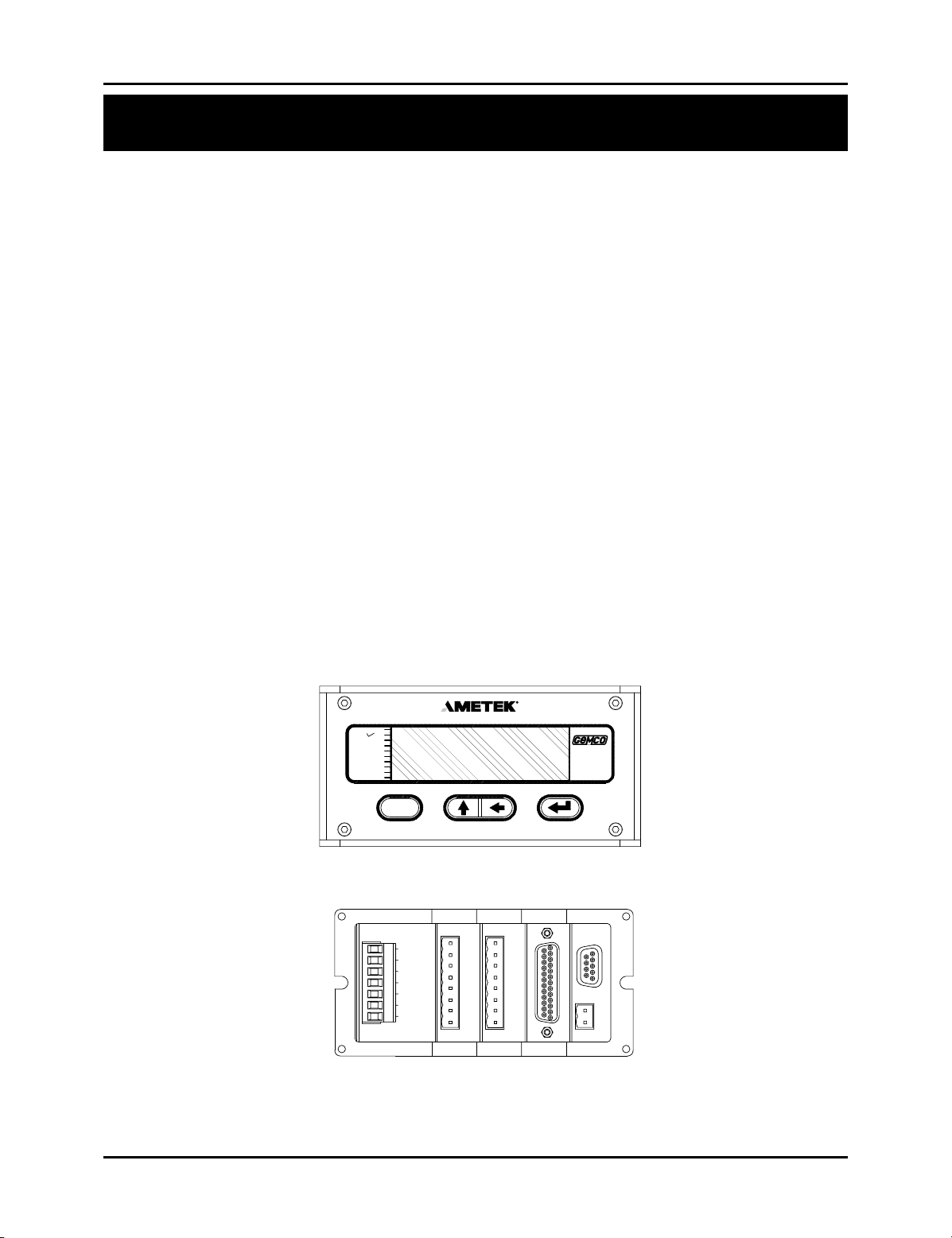
The Interface Module’s faceplate contains a 6-digit, seven-segment LED display and four
programming keys. The LED display is used to indicate the position, as well as to display
parameters when programming. The programming keys are used to program the Interface
Module. Ten small status LEDs are also provided. These LEDs are used to indicate the state
of the monitor during machine operation.
PROGRAM
FLT OK
MVT FLT
POS
RPM
UPR LIM
LWR LIM
AUX1
AUX2
AUX3
()
F
POWER
POWER SUPPLY
100-240VAC 50/60HZ
L1
L2
3 5 6412
GND
FLT CHK
}
AUX INP
7
}
FMPS01
POWER
FRONT
4
RELAY
R
E
L
A
Y
FMOR01
4
BACK
3
RSLVR
FMIR01
3
R
E
S
O
L
V
E
R
SERIES
2120
2 1
C.P.U.
D
G
T
L
O
U
T
P
U
T
FMMP01
2
1
Figure 2-1 Interface Module with Resolver/Digital Modules
2
Installation and Programming Manual
Page 7

Chapter 2: Hardware Overview
2.1: Standard Modules
This section provides descriptions of basic Interface Modules (also see Section 2.2: Input/Output
Modules).
Controller (FMMP01)
This module contains the Central Processing Unit (CPU) which is used to process data it receives from
the resolver or Linear Displacement Transducer (LDT). It then shows the position on the Interface
display. The controller is also responsible for continuously monitoring all programmed setpoints and
timing functions. To store programmed functions, including fi xed settings, the controller contains
battery-backed memory. This battery requires no maintenance and is non-replaceable. To allow for
remote communications with the Interface Module, RS-232 and RS-485 serial ports are available through
a D9 connector. The controller is located in slot 1 of the enclosure. (For wiring instructions, see Section
3.2: Wiring)
Power Supply (FMPS01)
This module supplies power to the Interface Module. It also contains a fault check relay and an auxiliary
input. The fault check relay is designed to take power away from the operating machine when a fault
occurs during machine operation, or when power is taken away from the Interface Module. In order for
this to perform it’s intended function, the fault check relay must be properly wired to the machine’s safety
interlock. For a listing of errors which will cause the fault check relay to deenergize, see Chart A-4 in
Appendix A: Error Messages. The auxiliary input is designed for the Move Detection Time-out and
Position Hold functions and accepts an 85-265 VAC input signal. The power supply is located in slot 5 of
the enclosure. (For wiring instructions, see Section 3.2: Wiring.)
2.2: Input/Output Modules
The PLC Interface Module can be used with a resolver or Linear Displacement Transducer (LDT). Either
input module will be located in slot 3 of the enclosure. You can identify the module type by the name
found on the back of the module.
Resolver (FMIR01) Input Option R1
This module is used with a Gemco resolver. The resolver assembly consists of a highly accurate and
repeatable brushless resolver, housed in an industrial-grade enclosure. The shaft position is calculated
from two analog signals that vary as a function of the angular rotation of the input shaft.
The brushless resolver works on the same principle as a rotary transformer to couple power into the rotor.
The construction of the brushless resolver consists of a two-phase stator and a single-phase rotor. Each
stator is positioned 90° apart from each other. The two stators continually provide two different output
voltages. Using these two outputs, the module performs a ratiometric conversion and provides an absolute
position. This results in a highly accurate and repeatable transducer having excellent reliability with an
infi nite resolution which can be converted by a resolver-to-digital converter into digital position data. This
module also provides the reset-to-preset input terminals. An input at these terminals will reset the position
display and outputs to a preprogrammed value. This input can be used to continuously compensate for
position drift caused by slippage in the drive mechanism turning the resolver.
Installation and Programming Manual
3
Page 8

Chapter 2: Hardware Overview
Variable Pulse (FMIP01) Input Option V1
This module is used with an LDT that provides its output in the form of a pulse width modulated RS-422
signal. This module only works with Gemco Series 951VP2110 LDT’s.
LDT Input (FMIP02) Input Option L1
This module will accept an output from a controlled pulse, start stop pulse or variable pulse
magnetostructive LDT. This card accepts a wide range of LDT inputs and provides faster updates than
the variable pulse version described above.
It allows the PLC Interface Module to receive the signals from the LDT. The pulse width signal is
converted to position data which the monitor displays. The module also provides +24 VDC to supply
power to the LDT. The module was designed to work with the Gemco Series 951 or 952CP or RS LDT.
However, other LDTs can be used with the module. If you are using a different type of LDT, contact the
factory for wiring and programming instructions.
This module also contains reset-to-preset input terminals. A signal at this input will reset the position
display and outputs to a preprogrammed value. This feature is useful for quick recalibration of the
system to a gauge block or known machine position.
Digital Output (FMOD01) Output Option D1, D2 or D3
This module is used to transmit parallel digital output data to a PLC or personal computer. The digital
output is fi eld confi gurable for position or velocity data in a binary, BCD or grey code format. This data
is updated every 50 microseconds. The electrical characteristics of this output data can be current sinking,
current sourcing or TTL which must be specifi ed in the module’s part number.
This module also provides two input pins for use as a fi eld confi gured latch or synchronized handshake
input. The latch input freezes the digital output data while the PLC reads it. The data is updated when the
input is released. When confi gured for synchronized handshake, the PLC must provide a clocked square
wave input into these input pins. Digital data is updated on each transition of the square wave and the PLC
is synchronized to read the updated position data after a 100 microsecond settling time.
This input accepts a 5 to 24 VDC source from the PLC to perform the latch or synchronized handshake
function described above. For details on wiring to the digital output board, see pages 17 & 18.
Analog Output (FMOA01) Output Option A1
This module is used to transmit position or velocity data to a PLC in an analog format. The module
provides two separate analog output channels that can be independently confi gured for position or
velocity data.
These analog outputs can be fi eld scaled over any range and confi gured for 0 - 10 VDC, 10 - 0 VDC,
-10 VDC to +10 VDC, 4 - 20 mA, 20 - 4 mA, 0 - 20 ma or 20 - 0 mA.
For applications that require remote indication it is recommended to use an aftermarket analog input
display or a digital input display. When using one of these displays the optional analog or digital output
board must be specifi ed in the part number.
4
Installation and Programming Manual
Page 9
Chapter 2: Hardware Overview
Relay Output (FMOR01)
This optional module contains two overtravel limit relays. These relays can be programmed to either
energize or deenergize upon reaching the programmed overtravel position. These relays will also actuate
upon detection of the system and operating errors listed in chart A-5 in Appendix A.
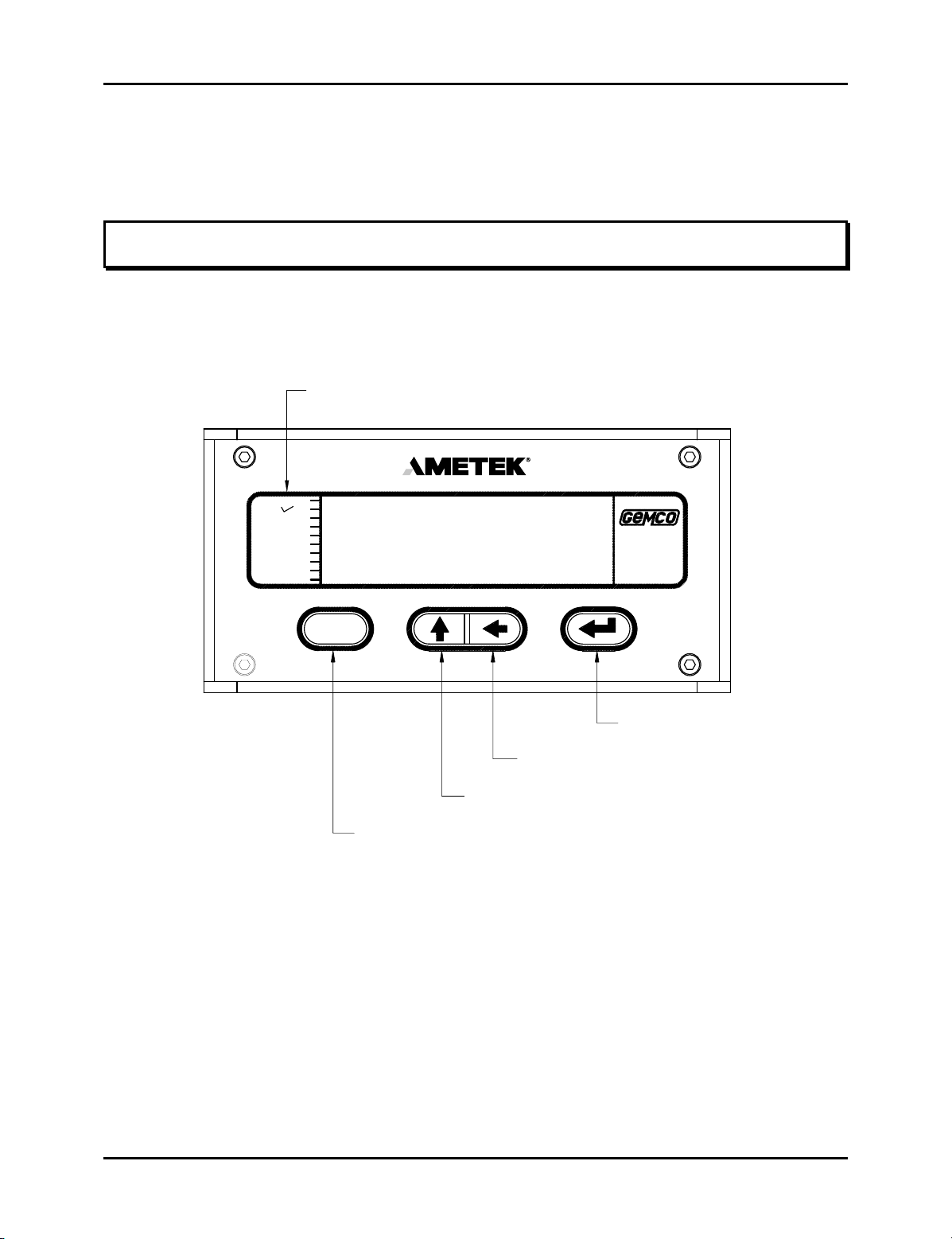
2.3: Status LEDs Defi ned
The Interface Module has 10 status LEDs and four programming keys. The LEDs provide information on
the monitor’s state during machine operation, and the programming keys are used to program functions
and perform basic operations.
Status LEDs
PROGRAM
FLT OK
MVT FLT
POSITION
RPM
UPR LIM
LWR LIM
AUX 1
AUX 2
AUX 3
SERIES
2120
()
F
Enter Key
Shift Key
Scroll Key
Function Key
Figure 2-2 Status LEDs and Programming Keys
PROGRAM
turns off when it is not. Functions cannot be programmed when this LED is off.
The program LED turns on when the Interface Module is in program mode and
FAULT OK The fault check OK LED turns on when the power supply’s fault check relay is
energized, indicating the system is OK. This LED will turn off when a fault is
detected, indicating that the fault check relay is deenergized.
MVT FLT The movement fault LED turns on when a movement fault is detected. (For more
information, see Move Detection Time-out in Section 4.3: Setup Functions.)
Installation and Programming Manual
5
Page 10

Chapter 2: Hardware Overview
POSITION This position LED turns on when the Interface Module is showing position in the
large LED display.
RPM The RPM LED turns on when the Interface Module is showing RPM in the large
LED display.
UPR LIM The upper limit LED refl ects the state of the relay when the value programmed in
the Upper End Limit function is reached. The relay can be programmed to energize
or deenergize upon reaching the programmed overtravel position. (For more
information, see Upper End Limit in Section 4.3: Setup Function).
LWR LIM The lower limit LED refl ects the state of the relay when the value programmed in
the Lower End Limit function is reached. The relay can be programmed to
energize or deenergize upon reaching the programmed overtravel position. (For
more information, see Lower End Limit in Section 4.3: Setup Functions.)
AUX 1 For future expansion.
AUX 2 For future expansion.
AUX 3 The auxiliary LED is programmable and can be used with the Position Hold
function. When enabled, this LED indicates when the position is being held. (For
more information, see Position Hold and Auxiliary LED in Section 4.3: Setup
Functions.)
The function key is used to begin a process for programming a function. When
this key is pressed, the Interface Module prepares itself for the entry of a specifi c
(F)
function number.
The scroll key is used to scroll through the Interface Module’s list of function
numbers, as well as other lists. This key is also used to increment selected digits
shown on the Interface Module’s LED display.
The shift key is used to move to (select) a specifi c digit shown on the Interface
Module’s LED display from right to left.
The enter key is selected after a function number has been entered. This begins
the programming process for the selected function. The enter key is also used to
program a value in a function.
NOTE: For more information on how to use the programming keys, see Chapter 4: Programming
6
Installation and Programming Manual
Page 11

Chapter 3: Mounting and Wiring
Chapter 3: Mounting and Wiring
This chapter provides instructions for mounting and wiring the PLC Interface Module. These instructions
have been divided into two sections: Section 3.1: Mounting and Section 3.2: Wiring.
Things to Consider
It is recommended that you consider the following before installing the PLC Interface Module:
To minimize the effects of electromagnetic interference (EMI), the monitor should be
mounted as far away as possible from motor starters, drives and control relays.
The monitor should be mounted in an area free of water spray, corrosive gases, fl ying
chips, or any other foreign matter that could cause damage to the unit.
If the module is mounted directly on the machine, it should be installed in an area
where shock and vibration will be minimized.
The module should be located in an area that is within the temperature and humidity
specifi cations. (See Appendix D: Specifi cations.)
3.1: Mounting
Interface Module
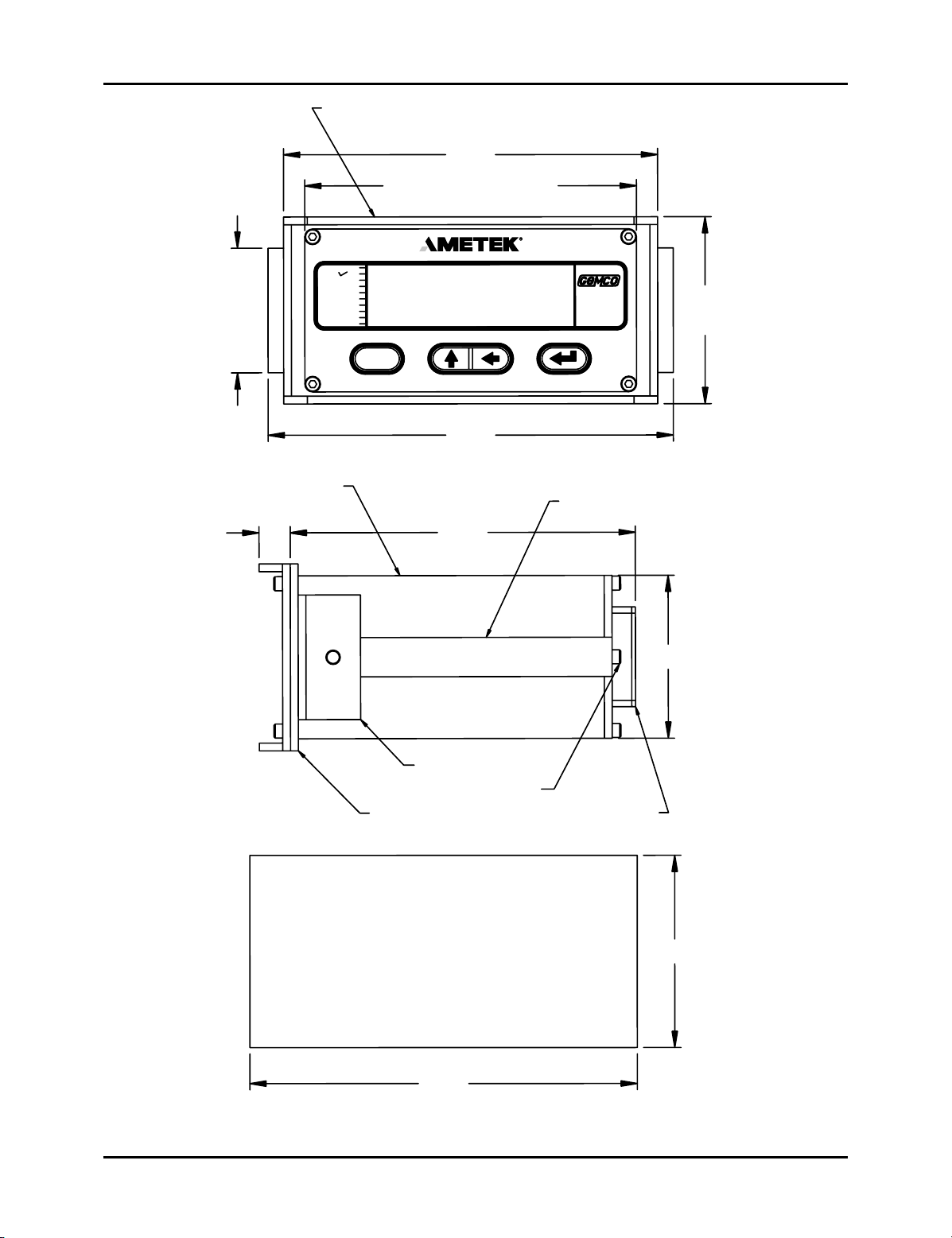
To assist you in mounting the PLC Interface Module, refer to Figure 3-1. Perform the following steps:
1. According to the dimensions as shown in Figure 3-1, cut out a section of the panel
you wish to mount the module in.
2. Remove the mounting rails on the left and right side of the unit by removing the
#6-32 UNC screws located on the rear of the unit.
3. Place the module in the cutout section of the panel.
4. From behind the panel, insert the two mounting rails into the module’s side grooves.
The feet of the rails must be inserted fi rst. See Figure 3-1 for the location of the
mounting rails.
The mounting rails secure the monitor by their feet being pressed against the back
of the panel.
Installation and Programming Manual
7
Page 12

Chapter 3: Mounting and Wiring
5. Insert each #6-32 UNC screw into each of the module’s screw holes.
6. Using a 7/64" Allen wrench, secure the screws into position. This will secure the
mounting rails. 8 to 10 inch pounds of torque is required.
Cabling
The signals from a resolver or LDT are inherently very immune to electrical noise. However, to ensure
trouble free operation in an industrial environment, it is recommended that these cables be routed in a
separate conduit isolated from all power handling leads. A continuous uninterrupted length of cable from
the transducer to the Interface Module is preferred. If fi eld splices to the cable are required, they must
be done in an isolated grounded junction box with no other power handling leads present. Shielded cable
must be used that has similar shielding as the standard Gemco cable and the shield must not be tied to
ground anywhere along the cable run except as shown in the wiring diagram in this manual.
The cabling should also be routed away from noise generating devices like variable frequency drives,
servo amplifi ers, solenoid valves or large contactors.
8
Installation and Programming Manual
Page 13
2
.
0
0
T
Y
P
Chapter 3: Mounting and Wiring
U
M
L
A
R
P
O
R
G
K
O
T
F
L
M
F
T
V
T
I
S
O
P
R
U
R
L
P
R
L
W
L
U
A
X
U
A
X
U
A
X
E
S
A
C
M
U
N
I
M
U
L
A
D
T
S
N
I
D
8
/
3
L
N
Z
E
I
U
E
M
B
0
0
.
6
H
T
ID
W
E
S
A
C
2
3
.
5
M
A
T
L
N
O
I
M
P
M
I
M
I
1
2
3
()
F
0
5
.
6
M
S
R
E
I
E
S
0
2
1
2
O
F
/
W
L
I
A
R
G
N
I
T
N
U
O
3
.0
0
T
O
3
5
.
0
5
.
A
G
"
/8
1
R
E
P
A
5
1
6
.
2
T
O
O
F
L
I
A
R
G
N
I
T
N
U
O
M
S
W
E
R
C
S
G
N
I
T
N
U
O
M
E
L
B
A
G
G
U
L
P
E
T
E
K
S
E
M
N
C
M
O
N
E
D
E
D
U
O
C
L
T
U
T
D
M
R
E
T
S
P
I
R
T
S
L
A
IN
7
6
.
2
8
3
.
5
Figure 3-1 Dimensional Drawing
Drawing E0232200
Installation and Programming Manual
9
Page 14
Chapter 3: Mounting and Wiring
3.2: Wiring
This section contains pinout diagrams for each module. System wiring diagrams follow.
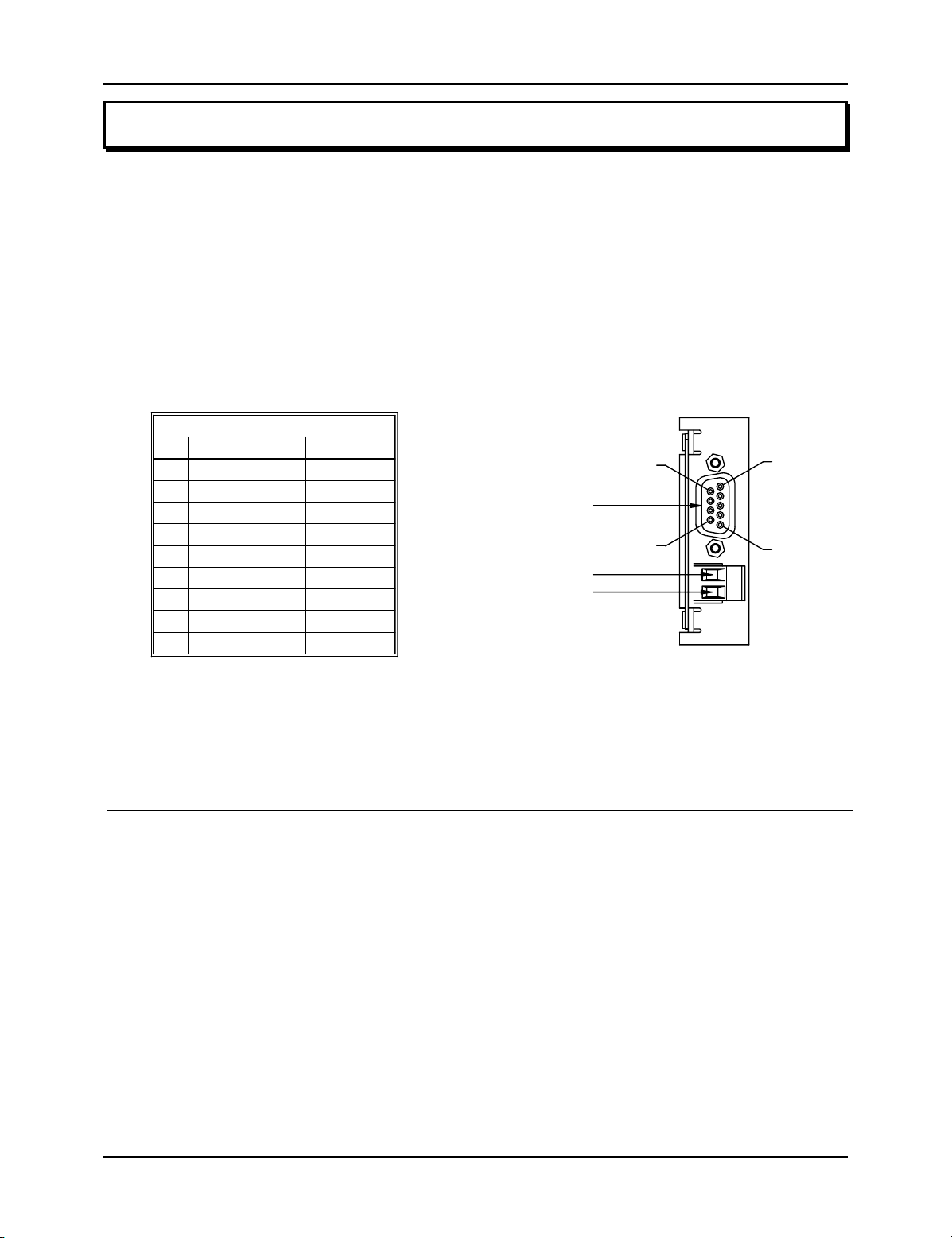
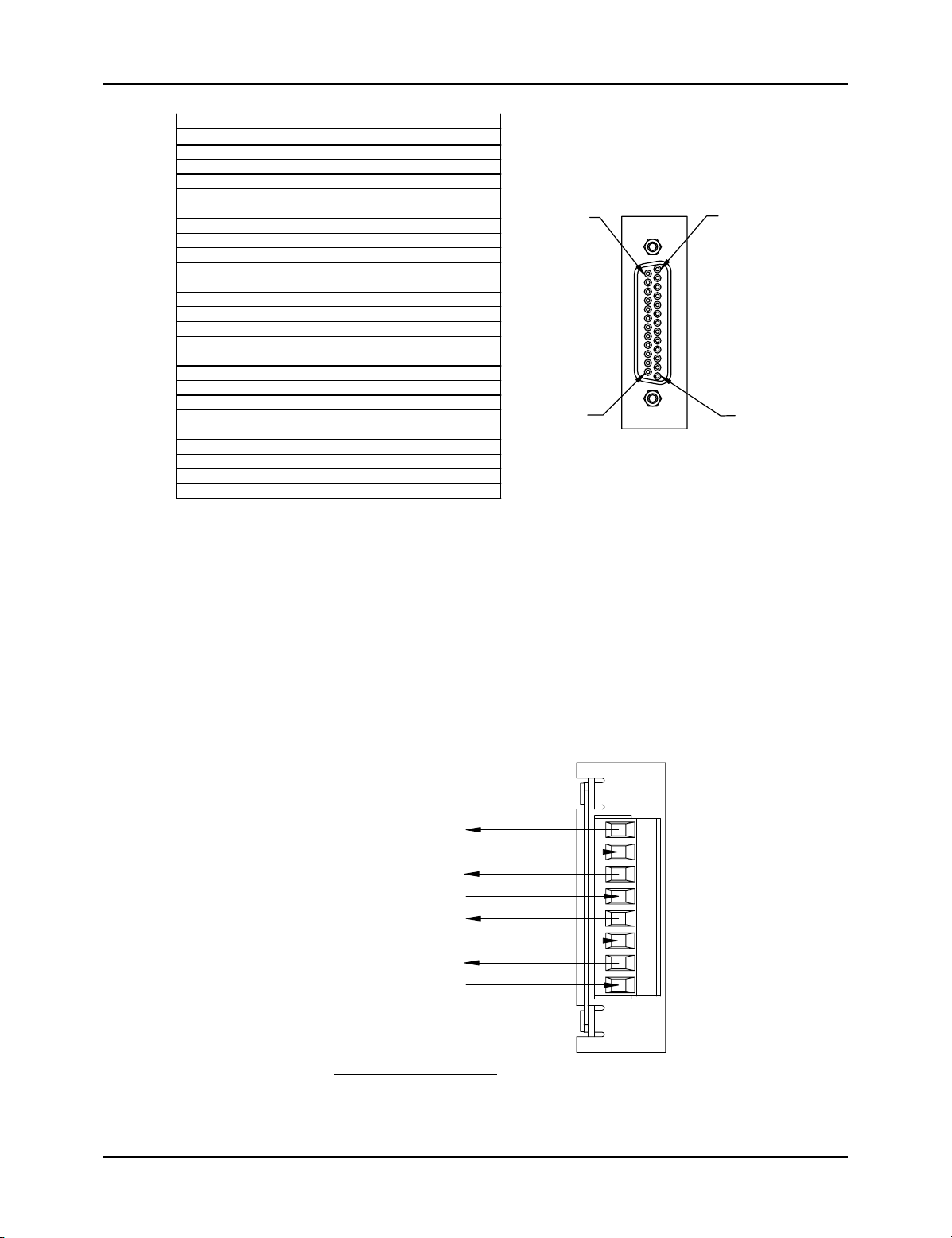
Controller Module (FMMP01)
The controller has two connectors: a D9 connector (J1) for RS-232 and RS-485 serial
communications, and a program lockout connector (J2) intended for a keyswitch. (See Figure
3-2). Making connections to both connectors is optional. However, the program lockout
connector must be jumpered to allow the unit to enter program mode. J2’s input rating is +5
VDC maximum dry contact or open collector (drain) only. Actuation voltage must be less than
+1.0 VDC at 0.2 mA. The terminal wire size is No. 22-12 AWG.
COMMUNICATIONS CONNECTOR
PIN SIGNAL NAME DIRECTION
GND CHASSIS
1
RXD RS-232
2
3
TXD RS-232
4
NO CONNECTION
5
GND SIGNAL
6
TX2+ RS-485
7
RTS RS-232
8
CTS RS-232
9
TX2- RS-485
OUTPUT
INPUT
I / O
INPUT
OUTPUT
I / O
INPUT +
{
INPUT -
(J1)
COMMUNICATIONS
CONNECTOR D9 FEMALE
(J2)
PIN 9
PIN 6
C.P.U.
PIN 5
PIN 1
21
FMMP01
Figure 3-2 Controller Pinout Diagram
Drawing E8002099
NOTE: The controller’s program lockout connector (J2) must be jumpered to allow the unit
to enter program mode.
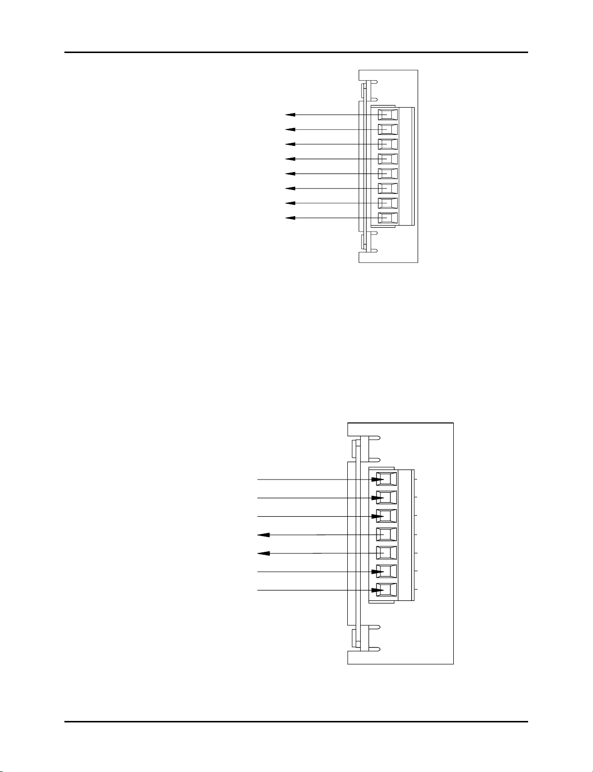
Relay Output Module (FMOR01)
The relay output module contains two overtravel limit relays. Each relay contains a N.O. contact
pair and a separate N.C. contact pair. (See Figure 3-3). The relay contacts are rated at 8 amps
250 VAC, 30 VDC, 1/4 HP 125, 250 VAC. The terminal wire size is 22-12 AWG.
10
Installation and Programming Manual
Page 15
Chapter 3: Mounting and Wiring
RELAY
NO
{
{
NO
NC
NC
NO
NO
NC
NC
RELAY 1
UPPER LIMIT
RELAY 2
LOWER LIMIT
Figure 3-3 Relay Output Pinout Diagram
Power Supply Module (FMPS01)
The power supply module has a main power input, an auxiliary input, and a fault check output.
(See Figure 3-4). Power input: 85-265 VAC at 450 mA maximum. Fault check output: 8 amps
250 VAC, 30 VDC, 1/4 HP 125, 250 VAC. It is recommended that the fault check contacts be
connected to the required safety interlock. Auxiliary input: 85-265 VAC at 12 mA maximum.
The terminal wire size for all connectors is No. 22-12 AWG. See page 3, 15 and 16 for use of
this special purpose input, concerning position hold and move detection.
21
3
4
5
687
FMOR01
POWER
INPUT
FAULT
CHECK
AUXILIARY
INPUT
{
Figure 3-4 Power Supply Pinout Diagram
L1
L2
GND
NO
{
NO
L1
{
L2
POWER SUPPLY
100-240VAC 50/60Hz
L1
21
L2
3
GND
4
{
FLT CHK
5
6 7
{
AUX INP
FMPS01
Installation and Programming Manual
11
Page 16
Chapter 3: Mounting and Wiring
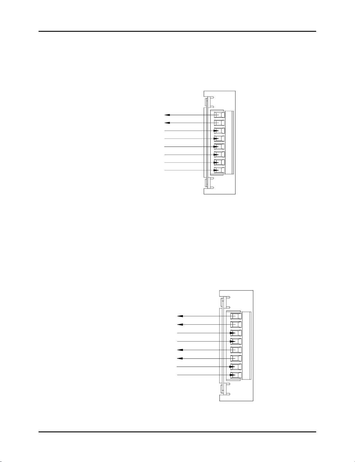
Resolver Module (FMIR01)
The resolver module has an eight-position connector. (See Figure 3-5). The terminal wire size
for all positions is No. 22-12 AWG. The reset-to-preset input is an edge sensitive input that
resets position data to a preprogrammed value. An open collector sinking device or dry contact
applied to these terminals activates the input. For programming of reset-to-preset value, see
Chapter 4: Programming.
RSLVR
1
2
3
4
5
867
FMIR01
Reset-to-Preset
Input
{
Input +
Input -
RH
RL
S3
S1
S2
S4
(See wiring
diagram for
ratings)
Figure 3-5 Resolver Pinout Diagram
Variable Pulse LDT Module (FMIP01) Input Option V1
The variable pulse LDT module has an eight-position connector. It is only necessary to connect
your LDT to positions 1 through 4. (See Figure 3-6). Positions 1 and 2 provide +24 VDC to
power the LDT. Positions 3 and 4 are used for the LDT’s pulse-width output signals. These
signals comprise an RS-422 differential input. Positions 5-8 are provided for future expansion.
The terminal wire size for all positions is No. 22-12 AWG. This module should only be used
with Gemco LDT model 951VP-2110 transducers. An open collector sinking device or dry
contact applied to the Reset to Preset terminals activates the input.
PROBE
+24VDC @135mA
PROBE VP -
Aux 24VDC @15mA
Reset-to-Preset
Input
GROUND
PROBE VP+
GROUND
Input +
{
Input -
1
2
3
4
5
867
12
FMIP01
Figure 3-6 Variable Pulse LDT Pinout
Diagram Input Option V1
Installation and Programming Manual
Page 17
Chapter 3: Mounting and Wiring
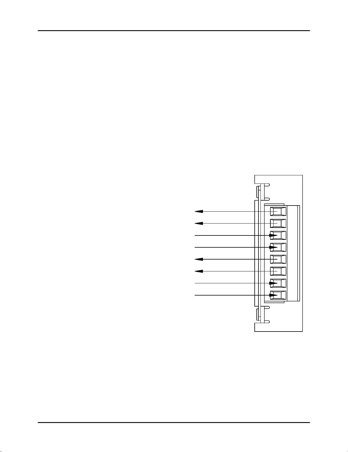
LDT Input (FMIP02) Input Option L1
This module will accept an output from a controlled pulse, start stop pulse or variable pulse
magnetostrictive LDT. (See Figure 3-7). This card accepts a wide range of LDT inputs and
provides faster updates than the variable pulse module as described on page 12.
The pulse width signal is converted to position data which the monitor displays. The module
also provides +24 VDC to supply power to the LDT. The monitor was designed to work with
the Gemco 951 or 952CP & RS LDTs. However, other LDTs can be used with the PLC
Interface Module. If you are using a different type of LDT, contact the factory for wiring and
programming instructions. The terminal wire size for all positions is No. 22-12 AWG.
The reset-to-preset input is an edge sensitive input that resets position data to a preprogrammed
value. A 5-24VDC source applied to these terminals activates the input. For programming of
reset value, see Chapter 4: Programming.
Reset-to-Preset
Input
+24VDC @ 135mA
GROUND
+RS422 IN
-RS422 IN
+RS422 OUT
-RS422 OUT
+ INPUT 5-24VDC
- INPUT
Figure 3-7 LDT Pinout Diagram Input Option L1
{
Common
PROBE
21
3
4
5
876
FMIP02
Digital Output (FMOD01) Output Option D1, D2 or D3
This module will output Binary, BCD, or Grey Code digital outputs in either current sinking,
current sourcing, or TTL level outputs. See Fig. 3-13A & B and Fig. 3-14 for wiring details. It
also contains a 5-24VDC source input for freezing the digital data while the PLC reads it. See
page 37, Latch/Synchronize Handshake.
Installation and Programming Manual
13
Page 18
Chapter 3: Mounting and Wiring
PIN
DIRECTION
1
2
3
4
5
6
7
8
9
10
11
12 IN
13 IN
14
15
16
17
18
19
20
21
22
23
24
25
DATA OUT BIT 0
OUT
DATA OUT BIT 2
OUT
DATA OUT BIT 4
OUT
OUT
DATA OUT BIT 6
OUT
DATA OUT BIT 8
DATA OUT BIT 10
OUT
OUT
DATA OUT BIT 12
DATA OUT BIT 14/INCREMENTAL OUT Z*
OUT
DATA OUT BIT 16/INCREMENTAL OUT A*
OUT
OUT
DATA OUT BIT 18/INCREMENTAL OUT B
OUT
BUSY*
BUS ENABLE*
GND
OUT
DATA OUT BIT 1
DATA OUT BIT 3
OUT
DATA OUT BIT 5
OUT
OUT
DATA OUT BIT 7
DATA OUT BIT 9
OUT
DATA OUT BIT 11
OUT
DATA OUT BIT 13
OUT
DATA OUT BIT 15/INCREMENTAL OUT B*
OUT
DATA OUT BIT 17/INCREMENTAL OUT Z
OUT
OUT
DATA OUT BIT 19/INCREMENTAL OUT A
SYNC
IN
VSRC+
IN
DESCRIPTION
Figure 3-8 Pinout Diagram Digital Output
Drawing E8002099
PIN25
PIN13
D
G
T
L
O
U
T
P
U
T
PIN1PIN14
Analog Output (FMOA01) Output Option A1
The Analog Output board provides two channels of analog output that can be independently
confi gured and scaled. Each channel can be confi gured for an output based upon position or
velocity. Velocity will be RPM if the sensor is a resolver or inches/mm per second if the input
sensor is an LDT. The two channels of analog output allow you to confi gure one analog output
to be based on position while the other channel provides a simultaneous indication of velocity.
ANALOG
CH1 VDC OUTPUT
CH1 VDC GROUND
CH1 CURRENT OUT
CH1 CURRENT RETURN
CH2 VDC OUTPUT
CH2 VDC GROUND
CH2 CURRENT OUT
CH2 CURRENT RETURN
423 867
51
FMOA01
14
Terminal Wire Size: No. 22-12 AWG
Figure 3-9 Pinout Diagram Analog Output
Drawing E8005099
Installation and Programming Manual
Page 19
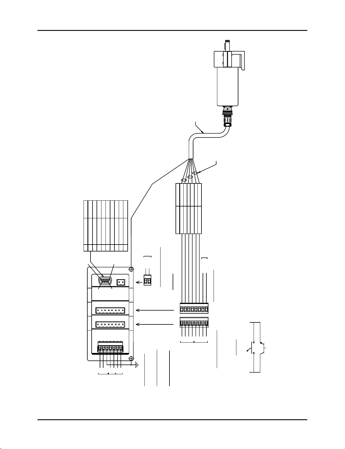
Chapter 3: Mounting and Wiring
RESOLVER
ASSEMBLY
SD0284200
DIRECTIONPIN SIGNAL NAME
INPUT
OUTPUT
TXD RS-232
RXD RS-232
GND CHASSIS
24365
1
PIN 5
1
C.P.U.
2
PIN 9
3
RSLVR
4
RELAY
+I/O
INPUT
OUTPUT
NO CONNECTION
GND SIGNAL
CTS RS-232
RTS RS-232
TX2+ RS-485
789
PIN 1
PIN 6
V
SER
L
R
E
O
REALY
-I/O
TX2- RS-485
SECURITY
PROGRAM
SHEILD TO CASE ASSEMBLY
INPUT+
INPUT-
1 2
1
FMMP01
2
3
FMIR01
4
FMOR01
(P/N SD0481500)
CABLE ASSEMBLY
SHIELD
PIN C
PIN B
PIN A
RESOLVER CONN.
WIRE COLORS
RED
PROGRAM SECURITY INPUT
ON AT < 1VDC @ 0.2mA
SINKING DEVICE, +5VDC MAX
SEE DIAGRAM 1 FOR SUGGESTED CONNECTIONS
12
RESOLVER
12
RELAY
PIN F
PIN E
PIN D
BLACK OF GREEN
BLACK OF WHITE
BLACK OF RED
WHITE
GREEN
S3RHRLS2S1
S4
534 6
5
34 6
AUX 3 INPUT
INPUT-
7
8
7
8
TWISTED PAIR
SOURCING DEVICE, +24V MAX
SINKING DEVICE, +5VDC MAX
ON AT > 21.6VDC @ 5mA
ON AT < 1VDC @ 5mA
AUX 3 INPUT RATING :
REVERSE GREEN-BLACK PAIR.
TO CHANGE RESOLVER DIRECTION
INPUT-
L1
1 2345
POWER
POWER SUPPLY
100-240VAC 50/60HZ
L1
GND
L2
L2
INPUT
POWER
FLT CHK
}
NO
NO
FAULT
CHECK
AUX INP
}
67
L2
L1
INPUT
AUXILIARY
FMPS01
POWER
85-265VAC @ 450mA
50-60 Hz
85-256VAC @ 12mA
AUXILIARY INPUT RATING :
POWER INPUT RATING :
RELAY CONTACT RATING :
FAULT CHECK
NCNONONONC
NO
LIMIT
UPPER
1/4 HP 125, 250VAC
8A 250VAC 30VDC
LIMIT NC INPUT+
LOWER
NC
UPPER & LOWER LIMIT
RELAY CONTACT RATINGS :
1/4 HP 125, 250VAC
8A 250VAC 30VDC
Figure 3-10 Resolver - Based System Wiring Diagram
Drawing E0235800
Installation and Programming Manual
(CLOSED)
PROGRAM
DIAGRAM 1
SWITCH CLOSED ENABLES PROGRAM MODE
OR
INPUT+
15
Page 20
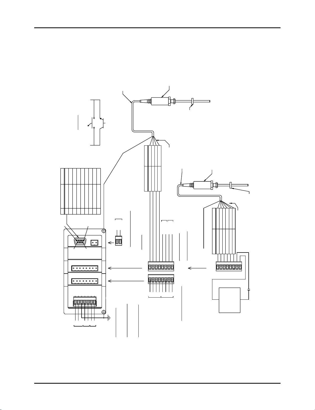
Chapter 3: Mounting and Wiring
PROGRAM
(CLOSED)
DIAGRAM 1
SWITCH CLOSED ENABLES PROGRAM MODE
OR
INPUT+ INPUT-
CABLE ASSEMBLY
(P/N SD0439700)
PIN C
PIN B
PIN F
PIN E
SERIES 951VP-2110
LINEAR TRANSDUCER
(P/N SD0439700)
CABLE ASSEMBLY
TO PROBE WILL RESULT.
RS PROBE TO FM1P01 INPUT CARD. DAMAGE
1. REQUIRED FOR RESET TO PRESET ONLY.
2. WARNING: DO NOT CONNECT A 951 CP OR
NOTES: UNLESS OTHERWISE SPECIFIED
MAGNET ASSEMBLY
LINEAR TRANSDUCER
SERIES 951 OR 952 CP, RS OR VPE
WARNING: SEE NOTE 2.
GND CHASSIS1
PIN SIGNAL NAME DIRECTION
PIN 5
C.P.U.
PROBERELAY
4 3 2 1
POWER
POWER SUPPLY
RXD RS-2322 OUTPUT
PIN 9
1
100-240VAC 50/60HZ
TXD RS-2323 INPUT
L1
L1
POWER
NO CONNECTION4
GND SIGNAL5
PROBEY
R
L2
GND
L2
INPUT
TX2+ RS-485
RTS RS-2327 INPUT
6 +I/O
PIN 1
PIN 6
ALE
FLT CHK
}
4523
67
NO
NO
FAULT
CHECK
CTS RS-2328 OUTPUT
TX2- RS-4859 -I/O
FMIP01
FMOR01 FMMP01
AUX INP
}
FMPS01
L1
L2
INPUT
AUXILIARY
POWER 4 3 2 1
PROGRAM
SECURITY
SHEILD TO CASE ASSEMBLY
INPUT+
INPUT-
21
PROGRAM SECURITY INPUT
SINKING DEVICE, +5VDC MAX
:
AUXILIARY INPUT RATING
85-256VAC @ 12mA
POWER INPUT RATING :
85-265VAC @ 450mA
50-60 Hz
FAULT CHECK
INSULATE AND TIE BACK
ALL UNUSED WIRES
RED
BLACK
BLUE
BROWN
WIRE COLORS PROBE CONN.
AUX POWER
AUX 3 INPUT
INPUT-
INPUT+
+24VDC
GROUND
ON AT < 1VDC @ 0.2mA
SEE DIAGRAM 1 FOR SUGGESTED CONNECTIONS
546
312
FMIP01
PROBE
312
RELAY
NONONCNCNONONC
LIMIT
UPPER
RELAY CONTACT RATING :
8A 250VAC 30VDC
1/4 HP 125, 250VAC
78
87564
LOWER
LIMIT
NC
AUX POWER RATING :
+24VDC @ 15mA
AUX 3 INPUT RATING :
RELAY CONTACT RATINGS :
UPPER & LOWER LIMIT
8A 250VAC 30VDC
SHEILD TO CASE ASSEMBLY
ON AT < 1VDC @ 2mA
SINKING DEVICE, +5VDC MAX
1/4 HP 125, 250VAC
PROBE CONN.
PIN B
PIN C
WIRE COLORS
BLACK
RED
21
PROBE
FMIP02
-
PIN E
PIN F
BROWN
BLUE
GRAY PIN K
3 68745
SUPPLY
OPTIONAL
CUSTOMER
DC POWER
SEE NOTE 1
MAGNET ASSEMBLY
PIN A
ALL UNUSED WIRES
INSULATE AND TIE BACK
WHITE
+
5-24VDC
6mA MAX.
16
Figure 3-11 LDT - Based System Wiring Diagram
Installation and Programming Manual
Page 21

CABLE ASSEMBLY
(P/N SD0403803) FOR 951
VP TRANSDUCER UNIT
PROGRAM
(CLOSED)
INPUT+ INPUT-
OR
JUNCTION BOX
(P/N SD0402100)
DIAGRAM 1
SWITCH CLOSED ENABLES PROGRAM MODE
SD04038031
CABLE TERMINATION KIT
(P/N SD0482700)
QTY PART NUMBER
SD04021001
SD04826001
CABLE ASSEMBLY
(P/N SD0482600)
PIN C
PIN B
PIN F
PIN E
SERIES 951VP-2110
LINEAR TRANSDUCER
Chapter 3: Mounting and Wiring
RS PROBE TO FM1P01 INPUT CARD. DAMAGE
TO PROBE WILL RESULT.
2. WARNING: DO NOT CONNECT A 951 CP OR
1. REQUIRED FOR RESET TO PRESET ONLY.
NOTES: UNLESS OTHERWISE SPECIFIED
MAGNET ASSEMBLY
WARNING: SEE NOTE 2.
LINEAR TRANSDUCER
SERIES 951 OR 952 CP, RS OR VPE
GND CHASSIS1
PIN SIGNAL NAME DIRECTION
PIN 5
C.P.U.
PROBERELAY
4 3 2 1
POWER
POWER SUPPLY
RXD RS-2322 OUTPUT
TXD RS-2323 INPUT
PIN 9
L1
1
100-240VAC 50/60HZ
L1
POWER
NO CONNECTION4
GND SIGNAL5
PROBEY
R
L2
GND
4523
L2
INPUT
TX2+ RS-4856 +I/O
RTS RS-2327 INPUT
CTS RS-2328OUTPUT
TX2- RS-4859-I/O
PIN 1
PIN 6
ALE
AUX INP
FLT CHK
}
}
67
L1
L2
NO
NO
INPUT
FAULT
CHECK
AUXILIARY
FMIP0X
FMOR01 FMMP01
FMPS01
POWER 4 3 2 1
RED
BLACK OF RED
WHITE
BLACK OF WHITE
WIRE COLORS PROBE CONN.
PART NUMBER
SD0403803
SD0402800
SD0402100
1
PROGRAM
SECURITY
SHEILD TO CASE ASSEMBLY
INPUT+
INPUT-
AUX POWER
AUX 3 INPUT
INPUT-
INPUT+
+24VDC
GROUND
CABLE TERMINATION KIT
(P/N SD0443800)
QTY
1
MAGNET ASSEMBLY
1
21
PROGRAM SECURITY INPUT
SINKING DEVICE, +5VDC MAX
ON AT < 1VDC @ 0.2mA
SEE DIAGRAM 1 FOR SUGGESTED CONNECTIONS
AUX POWER RATING :
78
546
312
PROBE
FM1P01
LIMIT
87564
NC
LOWER
LIMIT
UPPER & LOWER LIMIT
312
RELAY
NONONCNCNONONC
UPPER
RELAY CONTACT RATING :
8A 250VAC 30VDC
85-256VAC @ 12mA
FAULT CHECK
1/4 HP 125, 250VAC
AUXILIARY INPUT RATING :
POWER INPUT RATING :
85-265VAC @ 450mA
50-60 Hz
ON AT < 1VDC @ 2mA
+24VDC @ 15mA
AUX 3 INPUT RATING :
SINKING DEVICE, +5VDC MAX
RELAY CONTACT RATINGS :
8A 250VAC 30VDC
1/4 HP 125, 250VAC
SHEILD TO CASE ASSEMBLY
PROBE CONN.
PIN B
PIN C
WIRE COLORS
BLACK OF RED
RED
21
PROBE
FMIP02
-
SEE NOTE 1
PIN E
PIN F
BLACK OF WHITE
WHITE
GREEN PIN K
3 68745
SUPPLY
OPTIONAL
CUSTOMER
DC POWER
PIN A
ALL UNUSED WIRES
INSULATE AND TIE BACK
BLACK OF GREEN
+
5-24VDC
6mA MAX.
Figure 3-12 LDT - Based System w/Cable Termination Kit, Wiring Diagram
Drawing E0228600
Installation and Programming Manual
17
Page 22

Chapter 3: Mounting and Wiring
POWER
POWER SUPPLY
100-240VAC 50/60HZ
L1
21
L2
3
GND
4
FLT CHK
}
5
AUX INP
}
76
FMPS01
POWER
4
RELAY
R
E
L
A
Y
FMOR01
4
PIN25
RSLVR
FMIR01
PIN14
3
3
2
R
E
S
O
L
V
E
R
2
D25 FEMALE
PIN13
1
C.P.U.
D
G
T
L
O
U
T
P
U
T
FMMP01
1
PIN1
DIRECTION
PIN
1
2
3
4
5
6
7
8
9
10
11 OUT
12
13
14
15
16
17
18
19
21
22
23
25
OUT
OUT
OUT
OUT
OUT
OUT
OUT
OUT
OUT
OUT
IN
COMMON
OUT
OUT
OUT
OUT
OUT
OUT
OUT20
OUT
OUT
OUT
IN
POWER
DESCRIPTION
DATA OUT BIT 0
DATA OUT BIT 2
DATA OUT BIT 4
DATA OUT BIT 6
DATA OUT BIT 8
DATA OUT BIT 10
DATA OUT BIT 12
DATA OUT BIT 14
DATA OUT BIT 16
DATA OUT BIT 18
BUSY
BUS ENABLE (Optional, Consult Factory)
GND
DATA OUT BIT 1
DATA OUT BIT 3
DATA OUT BIT 5
DATA OUT BIT 7
DATA OUT BIT 9
DATA OUT BIT 11
DATA OUT BIT 13
DATA OUT BIT 15
DATA OUT BIT 17
DATA OUT BIT 19
LATCH/SYNC HANDSHAKE24
VSRC+
SEE NOTE 1
}
SEE NOTE 2
SEE NOTE 1
}
18
Figure 3-13A Digital Output Wiring Diagram
Drawing E0232200
Installation and Programming Manual
Page 23

OUTPUT RATING:
SINKNG DEVICE,
5 TO 24 VDC
100mA MAX
OUTPUT RATING:
SOURCING DEVICE,
5 TO 24 VDC
100mA MAX
DIGITAL
OUTPUT
MODULE
DIGITAL
OUTPUTS
DIGITAL
OUTPUT
MODULE
VSRC+
DIGITAL
OUTPUTS
GND
GND
13
DATA 0-19, BUSY
13
25
DATA 0-19, BUSY
Chapter 3: Mounting and Wiring
5 TO 24 VDC
-+
CUSTOMER DC
POWER SUPPLY
COM
{
DC INPUT
SOURCING
5 TO 24 VDC
-+
CUSTOMER DC
POWER SUPPLY
POWER
{
ALLEN BRADLEY
1771.IV
MODICON B833
OR EQUIVALANT
ALLEN BRADLEY
1771.IB
MODICON B825
OR EQUIVALANT
OUTPUT RATING:
TTL DEVICE,
VOH = 3.7 MIN @ IOH = -24mA
VOL = .44 MAX @IOL = 24mA
INPUT RATING:
24VDC @ 9mA MAX
LOW < 1.4V @ 0.5mA
HIGH > 2.0V @ 1mA
TTL COMPATIBLE
DIGITAL
OUTPUT
MODULE
GND
DIGITAL
OUTPUTS
DIGITAL
OUTPUT
MODULE
GND
BUS
ENABLE
LATCH/SYNC
HANDSHAKE
13
DATA 0-19, BUSY
13
12
24
DC INPUT
SINKING
COM
{
DC INPUT
5 TO 24 VDC
-+
CUSTOMER DC
POWER SUPPLY
SOURCING
COM
DC OUTPUT
SOURCING
ALLEN BRADLEY
1771.IG
MODICON B837
OR EQUIVALANT
ALLEN BRADLEY
1771.OB
MODICON B820
OR EQUIVALANT
Figure 3-13B Digital Output Wiring Diagram
Drawing E0232200
Installation and Programming Manual
19
Page 24

Chapter 3: Mounting and Wiring
22 GAGE TWISTED PAIR
WITH SHIELD AND DRAIN
CUSTOMER SUPPLIED
CUSTOMER
EQUIPMENT
SUPPLIED
20
C.P.U.
2 1
4 3
L1
1
POWER
POWER SUPPLY
100-240VAC 50/60HZ
SHEILD TO
CASE ASSEMBLY
FMMP01
CURRENT OUTPUT:
CH2 VDC OUTPUT
CH1 VDC OUTPUT
CH1 VDC GROUND
CH2 VDC GROUND
CH1 CURRENT OUT
CH1 CURRENT RETURN
-10VDC TO +10VDC
CH2 CURRENT OUT
VOLTAGE OUTPUT:
CH2 CURRENT RETURN
INTO 750 OHM LOAD
INTO 1K OHM LOAD
SOURCING 0 - 20mA
{
3
21
ANALOG
AUX INP
FLT CHK
L2
GND
}
4523
}
67
FMPS01
REFER TO MANUAL
FOR CORRECT SLOT
LOCATION BEFORE
INSTALLING MODULE
POWER 4 3 2 1
Fig 3-14 Wiring Diagram Analog Output
Drawing E8005090
Installation and Programming Manual
87645
FMOA01
Page 25

Chapter 4: Programming
Chapter 4: Programming
This chapter provides detailed descriptions and instructions for programming all Interface
Module’s functions. A complete list of functions (with brief explanations) can be found in
Appendix B: Function Summary Chart. This chapter divides the functions into the following
seven sections.
4.1 Resolver Input Confi guration Functions
4.2 LDT Confi guration Functions
4.3 Monitor Setup Functions
4.4 Relay Setup Functions
4.5 Digital Outputs
4.6 Analog Outputs
4.7 Program and Supervisory Mode Functions
Resolver confi guration functions are used to confi gure the Interface Module for use with a
Resolver. (Refer to these functions only if you are using a resolver as an input device). LDT
confi guration functions are used to confi gure the Interface Module for use with a Linear
Displacement Transducer. (Refer to these functions only if you are using an LDT as an input
device.) Confi guration functions should be programmed before any other functions. Monitor
setup functions provide the means to customize the monitor’s setup for a specifi c installation.
System setup functions provide the means to customize the Interface Module for a specifi c
installation. Program and supervisory mode functions are used to put the Interface Module in
either program or supervisory mode, as well as program the length of programming time and to
change the program mode access code.
NOTE: Resolver or LDT confi guration functions should be programmed fi rst before any other
type of programming is done. Refer only to your specifi c confi guration section,
depending on which input device you are using.
Before You Start
Before confi guring or programming the Interface Module, the following must be done in the
following order:
Jumper the monitor’s program lockout connector (J2). To jumper this connector,
see Section 3.2 Wiring.
Put monitor in program mode. For instructions on putting the monitor in
program mode, see Program Mode Access in Section 4.7: Program and Supervisory Mode Functions.
The program mode LED will turn on when the monitor is in program mode.
Installation and Programming Manual
21
Page 26

Chapter 4: Programming
Figure 4-1 calls out the Interface Module’s programming keys. Following this fi gure are
descriptions of these keys and how they work, as well as, a short tutorial on how to use the
keys.
PROGRAM
FLT OK
MVT FLT
POSITION
RPM
UPR LIM
LWR LIM
AUX 1
AUX 2
AUX 3
Status LEDs
()
F
SERIES
2120
Enter Key
Shift Key
Scroll Key
Function Key
Figure 4-1 Programming Keys
Programming Keys Defi ned
The Interface Module has four keys located on the front panel. These keys are used to program
functions and perform basic operations.
The function key is used to begin a process for programming a function.
(F)
The scroll key is used to scroll through the Interface Module’s list of
When this key is pressed, the Interface Module prepares itself for the entry
of a specifi c function number.
function numbers, as well as, other lists. To scroll to a particular function
number, continue to select the scroll key (after selecting the function key)
until the Interface Module displays the desired function number. The
scroll key is also used to increment selected digits on the monitor’s LED
display. Incrementing digits can be done to either select a function number
or a value for a function. To move to a specifi c digit on the display, use
the shift key. A fl ashing digit indicates it is activated to be incremented.
This key can also be used to get you quickly out of an incorrect parameter rather than having to restart the function entry process. For example, if an
invalid parameter was entered in the Upper End Limit function, you could
select the scroll key. This would take the monitor back to displaying the
current value, where you could re-enter a new value.
22
Installation and Programming Manual
Page 27

Chapter 4: Programming
The shift key is used to move to a specifi c digit shown on the Interface
The enter key is used for several purposes. For example, it is selected after
Module’s LED display. This can be done to either select a function number
or a value for a function. To move to a specifi c digit on the display, select
the function key and then the shift key. The right-most digit will then fl ash.
This indicates that the digit is activated to be incremented. (To increment
the digit, select the scroll key.) Continue to select the shift key until the
desired digit is activated.
a function number is displayed. This begins the programming process for
the selected function. The enter key is also used to program a value in a
function. This is done by selecting the enter key after the desired value is
displayed on the monitor’s screen.
4.1: Resolver Input Confi guration Functions
To customize the Interface Module to your specifi c resolver and application, you must fi rst make
some confi gurations. These confi gurations are made through the use of resolver confi guration
functions, which are described in this section. Perform these confi guration procedures before
entering other function values. After the resolver input has been confi gured, you may proceed on
to function 305 ( Display Power Up) and 307 (Resolver Reset-to-Preset).
Scale Factor (300)
Turns Counting (301)
Position Offset (302)
Turns Counting Wrap Around (308)
Scale Factor (300)
The Scale Factor function is used to program the number of counts or the resolution that one
revolution of the resolver results in. For example, when the function is programmed with a value
of 100, the Interface Module will count from 0 to 99 as the resolver completes a full revolution.
The default value for this function is 4096.
Turns Counting (301)
The Turns Counting function defi nes the number of revolutions the resolver must rotate before
the scale factor is reached. For example, when this function is set at 2 and the scale factor is
set at 100, the resolver will have to make two full revolutions before 100 counts is reached.
The Turns Counting Function can be disabled by setting its value to 0. When disabled, the
scale factor will cover its entire range in one revolution and roll over to 0 after one complete
revolution. When the Turns Counting function is set to 1, the total count will increase by the
scale factor for each revolution. For example, if the scale factor was set at 100 and turns counting
at 1, after fi ve revolutions, the monitor would display 500 counts. The default value for this
function is 0.
Installation and Programming Manual
23
Page 28

Chapter 4: Programming
Turns Counting Wrap Around (308)
When using the Turns Counting software described above where the Turns Count Function (301)
is set for 2 or more, you have the option of selecting the Wrap Around feature. Under normal
operation, you select a scale factor using function 300 followed by the number of turns required
to reach the selected scale factor using function 301. Upon reaching the selected scale factor,
the count will continue to increase at the same rate if the resolver continues rotating in the same
direction. With a scale factor of 100 and a turns count of 2, the module will count from zero
to 100 over the fi rst two rotations and will continue to increase by a factor of 100 for every
additional two turns in the same direction. The Wrap Around function allows you to program a
scale factor followed by the number of turns required to reach the scale factor. Upon reaching
one digit less than the scale factor, the display and output count wraps around to zero and begins
counting up at the same rate over continued rotation in the same direction.
Position Offset (302)
The Position Offset function is used to synchronize the resolver’s position with the actual
machine position. The default value for this function is 0. This function is used to adjust the
Interface Module’s indicated position so that it truly refl ects the machine’s position.
Programming Scale Factor (300)
This subsection provides the necessary instructions to program the scale factor. Once these steps
have been performed they will not have to be repeated.
(F)
1. Select the function key.
The monitor displays “F-----”.
10
2. Enter function number 10. (This is the Program Mode Access function which
allows you to put the monitor in program mode. Only when the Interface
NOTE: If the Interface Module displays only one zero (i.e. “0”), then the program lockout
connector is not jumpered. For wiring instructions, see Section 3.2: Wiring.
Enter program mode
access code
Module is in program mode can other functions be programmed.) Select the
enter key.
The monitor displays “000000”.
3. Enter the program mode access code. The default code is 2100. Select the
enter key.
24
The monitor is now in program mode. The program mode LED is turned on.
Installation and Programming Manual
Page 29

Chapter 4: Programming
NOTE: The Interface Module is defaulted to stay in program mode for 120 seconds. The
monitor will drop out of program mode if a key is not pressed within this time. If this
occurs, you will have to repeat steps 1-3. Further, the access code (2100) is provided
initially. This code can be changed through the use of the New Access Code function.
For security reasons, this function can only be implemented when the monitor is in
supervisory mode. For more information on, New Access Code, contact the factory.
(F)
300
Adjust the Turns Counting Factor (301)
(F)
301
Number
of Turns
4. Select the function key.
The monitor displays “F-----”.
5. Select function number 300 (Scale Factor function). Select the enter key.
The monitor displays currently programmed scale factor.
6. Enter the desired scale factor value, including digits up to a maximum of three
spaces to the right of the decimal point. Select the enter key.
7. Select the function key.
The monitor displays “F-----”.
8. Select function number 301 (Turns Counting function). Select the enter key.
The monitor displays currently programmed turns counting factor
9. Enter desired number of turns to reach scale factor. Select enter key.
Select Wrap Around Feature (308)
(F)
308
Enter 0 or 1
10. Select Function Key.
The monitor displays “F----”.
11. Select Function 308 (Wrap Around Feature). Select enter key.
The monitor displays 0 or 1.
0 = Wrap Around Disabled
1 = Wrap Around Enabled
12. Enter 0 or 1. Select enter key.
Installation and Programming Manual
25
Page 30

Chapter 4: Programming
Program Position Offset (302)
(F)
13. Select the function key.
The monitor displays “F----”.
302
14. Select function number 302 (Position Offset Function). Select the enter key.
Enter desired
reading
The monitor displays the current position.
15. Enter the actual or desired machine position reading. Select the enter key.
After confi guring the encoder module for use with a resolver, you can proceed
to Section 4.3: Monitor Setup functions.
Display Power Up (305)
This function is used to set what will be displayed on Power Up.
(F)
16. Select the function key.
The monitor displays “F----”.
305
17. Select function number 305 (Power Up Function). Select the enter key.
Enter 0 or 1
The monitor displays 0 or 1.
0 = Power Up Displaying Position
1 = Power Up Displaying RPM
18. Enter 0 or 1. Select enter key.
Resolver Reset-to-Preset (307)
The reset-to-preset input is an edge sensitive input that resets position data to a preprogrammed
value. An open collector sinking device or dry contact applied to these terminals activates
the input.
(F)
19. Select the function key.
The monitor displays “F----”.
307
20. Select function number 307 (Resolver Reset-to-Preset). Select the enter key.
The monitor displays current value.
26
Installation and Programming Manual
Page 31

Chapter 4: Programming
Enter Desired
Position
21. Enter desired Reset Value. Select the enter key.
NOTE: If 301 is set to 0, the Reset Value must be less than the Scale Factor.
4.2: LDT Confi guration Functions
There are two input cards available for use with LDTs.
1. Specifi ed as option V1 in the part number and is labeled (FMIP01) on the card.
2. Specifi ed as option L1 in the part number and is labeled (FMIP02) on the card.
The confi guration of the system is different depending on which module you have ordered.
Determine which module you have and proceed to the section below for programming
instructions.
Option V1 - This module can only be used with Gemco LDTs with a part number starting
with 951VP1992 or 951VP2110.
Wire speed and recirculations for these LDTs have been confi gured at the factory for maximum
resolution.
NOTE: Always refer to the LDT legend plate for programming wire speed (Function 300). The
wire speed will always be between 500.000 and 600.000 micro sec./inch.
Option L1 - This module is designed to be used with any LDT with digital output. These
include Series 951, 952 with VP, RS or CP outputs.
This module provides faster updates of position while using the LDT with standard wire speeds.
NOTE: Review the LDT legend plate for correct wire speed. Wire speed will always be
between 8.000 and 10.000 micro sec./inch.
4.2
NOTE: If option L1 is used, the fi rst step in confi guration must be Function 307 (LDT Type),
which tells the module which LDT is being used.
NOTE: Before an LDT confi guration function can be programmed, the Interface Module must
be in program mode. To put the monitor in program mode, see Program Mode Access
in Section 4.7: Program and Supervisory Mode Functions.
Installation and Programming Manual
27
Page 32

Chapter 4: Programming
Wire Speed (300)
Programming of the wire speed synchronizes the performance of the module with the performance
of the LDT. You will fi nd the wire speed on the legend plate of your LDT.
To program wire speed, perform the following steps:
(F)
1. Select the function key.
300
Enter new
value
The monitor displays “F-----”.
2. Select function number 300. Select the enter key.
The monitor displays the current wire speed.
3. Enter the new wire speed value. Select the enter key.
Count Direction (301)
The Count Direction function is used to change the direction the display counts as the LDT’s
magnet travels along the guide tube. A 0 value will cause the position value to increase as
the magnet moves away from the LDT head. A value of 1 will cause the position value to
increase as the magnet moves toward the LDT head. The default for this function is 1. For further
explanations, see Figure 4-2. To change the value of the Count Direction function, perform the
following steps:
(F)
301
1. Select the function key.
The monitor displays “F-----”.
Enter either
0 or 1
28
2. Select function number 301. Select the enter key.
The monitor displays the function’s current value.
3. Enter either a 0 or 1. Select the enter key.
Installation and Programming Manual
Page 33

Chapter 4: Programming
Count Direction Function = 0
0
When the Count Direction Function
is programmed with a value of 0, the
display value will increase when the
LDT’s magnet assembly is moving away
from the head of the LDT.
100
Count Direction Function = 1
100
When the Count Direction Function
is programmed with a value of 1, the
display value will increase when the
LDT’s magnet assembly is moving
toward the head of the LDT.
0
Figure 4-2 Count Direction Function Drawing
Position Offset (302)
NOTE: The display will read in inches or millimeters when used with an LDT. Make sure
the unit of measurement function is selected to your desired units before entering the
value for the Position Offset function. The unit of measurement is set in inches at the
factory. For instructions on selecting the unit of measurement, see Unit of Measurement
in Section 4.3: Monitor Setup Functions.
The Position Offset function is used to synchronize the monitors displayed value with actual
machine position. This value can range from -99.999 to 999.999 inches. With the machine
stationary at a known position, enter the desired position value using this function:
(F)
1. Select the function key.
The monitor displays “F-----”.
302
2. Select function number 302. Select the enter key.
Enter desired
reading
The monitor displays the current position.
3. Enter the new position value. Select the enter key.
Installation and Programming Manual
29
Page 34

Chapter 4: Programming
Fault Pulse Time (306)
Most magnetostrictive LDTs send out a fault pulse during a fault condition. The series 2120
Interface Module is preset for use with all Gemco LDT products. The Fault Pulse Time function
is used to program the pulse time of the fault signal sent by an LDT not manufactured by
Gemco. When the monitor receives a fault signal of this pulse time, it will indicate an error (see
Appendix A: Error Messages). The default for this function is 10 microseconds. This value
can range from 1 to 99 microseconds. A 0 is entered in this function to disable it. To change the
value of the fault pulse time or disable this function, perform the following steps:
NOTE: Do not change the value unless using an LDT other than Gemco.
(F)
1. Select the function key.
The monitor displays “F-----”.
306
2. Select function number 306 . Select the enter key.
The monitor displays the function’s current value.
LDT Output Type (307)
This function is used to confi gure the L1 input board for use with a specifi c LDT output. Review
legend plate of the LDT for output type, i.e. CP, RS or VP. Perform the following steps:
(F)
307
Enter New
Value
0 thru 3
3. Enter a 0 to disable this function or enter a new fault pulse time. Select
the enter key.
1. Select the function key.
The monitor displays “F-----”.
2. Select function number 307 . Select the enter key.
Enter either:
0 = CP
1 = RS
2 = VP (external interrogation) (See Note below)
3 = VP (internal interrogation)*
3. Select enter key.
*If used, consult the factory for additional settings.
NOTE: The Variable Pulse with external interrogation mode is not compatible with the 952 probe.
When using a 952 probe, select a different mode of operation.
30
Installation and Programming Manual
Page 35

Chapter 4: Programming
After confi guring the Interface Module for use with an LDT, you can proceed to Section 4.3:
Monitor Setup Functions.
LDT L1 Input Reset-to-Preset (311)
The reset-to-preset input is an edge sensitive input that resets position data to a preprogrammed
value. A 5-24VDC source applied to these terminals activates the input.
(F)
1. Select the function key.
The monitor displays “F----”.
311
2. Select function number 311 (LDT L1 Input Reset-to-Preset Function). Select
Enter desired
value
the enter key.
The monitor displays the current value.
3. Enter desired Reset-to-Preset value. Select the enter key.
4.3: Monitor Setup Functions
This section provides descriptions and instructions for the Interface Module setup functions.
These functions provide the means to customize the monitor’s setup for a specifi c installation.
Before any of these functions can be programmed, the monitor must be in program mode. To
put the monitor in program mode, see Program Mode Access in Section 4.7: Program and
Supervisory Mode Functions. The following is a list of the monitor setup functions:
Unit of Measurement (14)
Decimal Location (13)
Position Hold (15)
Auxiliary LED (16)
Unit of Measurement (14)
NOTE: This function applies to LDT inputs only.
The Unit of Measurement function is used to select the unit of measurement in which position
data is displayed. Measurements can be either in inches or millimeters. Enter 0 to select inches
or enter 1 to select millimeters. The default for this function is 0. To change the unit of
measurement, perform the following steps:
Installation and Programming Manual
31
Page 36

Chapter 4: Programming
(F)
1. Select the function key.
The monitor displays “F-----”
14
2. Enter function number 14. Select the enter key.
Enter either 0
or 1
The monitor displays the function’s current value.
3. Enter either 0 or 1. Select enter key.
NOTE: If you change the unit of measurement, the decimal location shown on the monitor’s
LED display will change to the default position for the unit of measurement selected.
If you select millimeters, position data will be displayed in hundredths; selecting inches
will display data in thousandths. For more information, see Decimal Location.
Decimal Location (13)
The Decimal Location function is used to program the resolution of the Interface Module and all
position data shown on the monitor’s LED display. Resolution can be either displayed in whole
units, tenths, hundredths, or thousandths. Resolution choices correspond to the following values:
0 = whole unit; 1 = tenths; 2 = hundredths; and 3 = thousandths. To change the resolution shown
on the monitor’s LED display, perform the following steps:
(F)
13
1. Select the function key.
The monitor displays “F-----”
2. Select function number 13. Select the enter key.
Enter either 0,
1, 2, or 3
The monitor displays the function’s current value.
3. Enter either a 0, 1, 2, or 3. Select the enter key.
Position Hold (15)
The Position Hold function stops the monitor from displaying irrelevant fl uctuations during
periods of high vibration at the sensor. When the monitor’s auxiliary input is activated, this
function will hold the last position read. Either 0, 1, or 2 can be programmed in this function.
Entering 1 will cause the monitor to hold the last position read when power is applied to the
auxiliary input. Entering 2 will cause the monitor to hold the last position read when power
is taken away from the auxiliary input. Entering 0 disables this function. The default for this
function is 0. Enabling this function disables the Move Detection Time-Out function. When
the Position Hold function is enabled, the value for the Move Detection Time-Out is then
32
Installation and Programming Manual
Page 37

Chapter 4: Programming
used for the Position Hold dwell time. The position hold dwell time is the amount of time
the monitor continues to hold the displayed position after the auxiliary input is released (or
activated, depending on the input’s programmed state). To enable or disable the Position Hold
function, perform the following steps:
(F)
15
Enter either 0,
1, or 2
1. Select the function key.
The monitor displays “F-----”
2. Enter function number 15. Select the enter key.
The monitor displays the function’s current value.
3. Enter either 0, 1, or 2. Select the enter key.
NOTE: The default time for the position hold dwell may be too long for your application. To
change this value for your application, perform the following steps.
(F)
12
4. The default value for the position hold dwell time function is 5.00 seconds. To
change this value, select the function key.
The monitor displays “F-----”
5. Enter function number 12. Select the enter key.
Enter new
dwell value
NOTE: The Position Hold function only holds the position on the monitor’s LED display.
The monitor displays the current value for the position hold dwell time. This
value is in seconds.
6. Enter the new dwell time. Select the enter key.
Internally, the position, upper and lower limit relays, digital and analog outputs are
continually being updated. In addition, the auxiliary LED can be used to indicate when
a position hold occurs. However, this LED must be selected for this feature. To enable
this LED, see Auxiliary LED.
Auxiliary LED (16)
The Auxiliary LED function is used to enable the monitor’s auxiliary LED. This LED is
currently used to indicate that the position hold input is active. (For more information, see
Position Hold). Either 0 or 1 can be programmed in this function. Entering 0 will disable the
LED. Entering 1 will enable the LED to turn on when a position hold occurs. The default for
this function is 0. To enable or disable the auxiliary LED, perform the following steps:
1. Select the function key.
Installation and Programming Manual
33
Page 38

Chapter 4: Programming
(F)
The monitor displays “F-----”
16
2. Select function number 16. Select the enter key.
Enter either 0
or 1
The monitor displays the function’s current value.
3. Enter either 0 or 1. Select the enter key.
Move Detection Time-out (12)
The Move Detection feature is used to monitor the time between when a signal is sent to initiate
machine movement and when movement is actually detected. The default value for this function
is 5.00 seconds. This value can range from 0 to 99.99 seconds. Entering a 0 disables this
function. The purpose of this function is to detect a possible jam or drive component failure.
When power is applied to the drive mechanism, the Interface Module’s auxiliary input is wired
to receive an AC voltage. When this occurs, the Interface Module begins to look for movement.
If movement is not detected within the programmed time, the upper and lower limit relays will
de-energize and the fault check relay will open. Also, the movement fault LED will turn on and
the monitor will display an error message (see Appendix A: Error Messages). This error will
have to be cleared before machine operation can resume. To change the move detection time-out
value or disable the function, perform the following steps:
(F)
12
Enter new
time-out
value
1. Select the function key.
The monitor displays “F-----”
2. Enter function number 12. Select the enter key.
The monitor displays the function’s current value.
3. Enter the new time-out value. Select the enter key.
NOTE: The power supply’s auxiliary input must be wired properly in order for the Move
Detection Time-Out function to work. For instructions on wiring the auxiliary input,
see Section 3.2: Wiring.
4.4: Relay Setup Functions - Option K1
If your system includes the optional relay module (K1), the following function numbers are used
for setup. Before these functions can be programmed, the monitor must be in program mode.
34
Installation and Programming Manual
Page 39

Chapter 4: Programming
To put the monitor in program mode, see Program Mode Access in Section 4.7: Program and
Supervisory Mode Functions. The following is a list of the press setup functions:
Upper End Limit (400)
Lower End Limit (401)
Relay State (402)
Relay Override (403)
Upper End Limit (400)
The Upper End Limit function is used to program the position value at which the upper end limit
relay actuates. If the displayed value reaches or exceeds the value programmed in this function,
the upper limit relay and the upper limit LED will actuate. (For wiring instructions, see
Section 3.2: Wiring.) The default for this function is 999.999 inches. This value can range
from 0 to 999.999 inches. To program a value for the Upper End Limit function, perform
the following steps:
(F)
1. Select the function key.
400
The monitor displays “F-----”
Enter upper
limit
NOTE: To temporarily override the upper end limit relay, see Relay Override.
2. Enter function number 400. Select the enter key.
The monitor displays the function’s current value.
3. Enter the new value. Select the enter key.
Lower End Limit (401)
The Lower End Limit function is used to program the position value at which the lower end
limit relay actuates. If the displayed value reaches or goes below the value programmed in this
function, the lower limit relay and the lower limit LED will actuate. (For wiring instructions,
see Section 3.2: Wiring.) The default for this function is 0.000 inches. This value can range
from 0 to 999.999 inches. To program a value for the Lower End Limit function, perform the
following steps:
(F)
401
1. Select the function key.
The monitor displays “F-----”
2. Enter function number 401. Select the enter key.
Installation and Programming Manual
35
Page 40

Chapter 4: Programming
Enter lower
end limit
The monitor displays the function’s current value.
3. Enter the new value. Select the enter key.
NOTE: To temporarily override the lower end limit relay, see Relay Override.
Relay State (402)
The Relay State function is used to program the Interface Module’s upper and lower limit relays
to either energize or de-energize when their programmed value is reached or exceed. Either a 0
or 1 can be programmed in this function. Entering 0 will cause the relays to energize during
normal machine operation, and de-energize when a limit is exceeded or when an error occurs.
Entering a 1 will cause the relays to de-energize during normal machine operation, and energize
when a limit is exceeded or when an error occurs. The default for this function is 0. To change
the state of these relays, perform the following steps:
(F)
402
1. Select the function key.
The monitor displays “F-----”
Enter either
0 or 1
2. Enter function number 402. Select the enter key.
The monitor displays the function’s current value.
3. Enter either a 0 or 1. Select the enter key.
Relay Override (403)
The Relay Override function is used to temporarily override end limit relays after they have
actuated due to an overtravel condition. (For more information, see Upper End Limit and Lower
End Limit.) To override either the upper or lower limit relays, perform the following steps:
(F)
1. Select the function key.
The monitor displays “F-----”
403
Enter 2110
2. Enter function number 403. Select the enter key.
The monitor displays “000000”
3. Enter the override code 2110. Select the enter key.
36
Installation and Programming Manual
Page 41

Chapter 4: Programming
NOTE: After overriding either the upper or lower limit relays, the operator should move the
machine back into its normal operating range between its upper and lower limits. If the
machine is again moved in the wrong direction (towards the limits), the upper or lower
limit relays will again actuate. Step 1 - 3 will have to then be repeated.
4.5: Digital Outputs
If your system has been purchased with the optional digital output module, the following
programming sequence will be used to confi gure the board for compatibility with the PLC input
card. See pages 15 and 16 for wiring details.
Output Type (200)
This function will set up the D25 connector on the digital board to output the current position
value in a Binary, BCD or Gray code format:
(F)
1. Select the function key.
The monitor displays “F-----”
200
2. Enter function 200. Select the enter key.
Enter either
0, 1 or 2
Latch/Synchronize Handshake (201)
This function defi nes which of the two methods will be used to stabilize position data while
the PLC reads. The two options are Latch or Synchronize Handshake. Synchronize Handshake
tells the digital board to update on the transitional edge of a clocked square wave input (pin
24). Latch tells the digital board to update continuously until the latch input pin is activated by
driving it high, then the outputs will freeze. Data will immediately update to a current value
upon removal of the latch input.
The monitor displays the function’s current value.
3. Enter either 0, 1 or 2.
0 = Binary (default)
1 = BCD
2 = Gray
Select the enter key.
NOTE: If set for Synchronize Handshake, the position data will never update if a square wave
input is not seen on pin 24. Allow a 100 microsecond settling time after each transition
before reading the output for both the Latch and Synchronize Handshake input.
(F)
1. Select the function key.
The monitor displays “F-----”
Installation and Programming Manual
37
Page 42

Chapter 4: Programming
201
Enter either
0 or 1
2. Enter function 201. Select the enter key.
The monitor displays the function’s current value.
3. Enter either 0 or 1.
0 = Latch (default)
1 = Synchronize
Select the enter key.
Logic Level (202)
This function will set up selection of either high true or low true logic.
(F)
1. Select the function key.
The monitor displays “F-----”
202
2. Enter function 202. Select the enter key.
Enter either
0 or 1
The monitor displays the function’s current value.
3. Enter either 0 or 1.
0 = Low True
1 = High True (default)
Select the enter key.
Error Condition Output State (203)
This function allows you to select how the digital outputs will react to a failure in the Interface
Module, transducer and/or cable. The following three options describe what will happen on a
failure.
(F)
1. Select the function key.
The monitor displays “F-----”
203
2. Enter function 203. Select the enter key.
The monitor displays the function’s current value.
0, 1 or 2
Enter either
3. Enter either 0, 1 or 2.
0 = All Outputs Off (default)
1 = All Outputs On
2 = Last Valid Position
Select the enter key.
38
Installation and Programming Manual
Page 43

Chapter 4: Programming
4.6: Analog Outputs
The Analog Output board provides two channels of analog output that can be independently
confi gured and scaled. Each channel can be confi gured for an output based upon position or
velocity. Velocity will be RPM if the sensor is a resolver or inches/mm per second if the input
sensor is an LDT. The two channels of analog output allows you to confi gure one analog
output to be based on position while the other channel provides a simultaneous indication of
velocity.
Each of the two analog output channels generate a simultaneous voltage and current output. You
can use either the current or voltage output on one channel but not both.
The following programming sequences require that you specify your intent to use either the
voltage or current output for each channel prior to programming the output scaling. You can
confi gure one analog channel for use of its voltage output and confi gure the other channel for
current.
The analog output board will be factory installed in slot 2 or slot 4 of the Series 2120 module’s
chassis. Look at the back of your Series 2120 module and verify which slot your analog output
board has been installed in. The following programming function numbers are shown with an
“X” as the fi rst digit. The “X” must be replaced with the number 2 or 4 which corresponds to the
slot in which your analog output board was installed at the factory.
NOTE: Boards cannot be changed from their factory supplied slot location in the fi eld.
It is recommended that you confi gure and program the analog output in the following sequence.
Perform all programming steps for one output channel before proceeding to the other output
channel.
REPLACE “X” WITH SLOT LOCATION
Analog Output Channel 1
A) Select analog output based on position or velocity
(F)
1. Select the function key.
The monitor displays “F-----”
X01
2. Enter function number X01. Select the enter key.
The monitor displays the current function value.
Enter
0 or 1
0 = position
1 = velocity
3. Leave current value or change. Select enter key.
Installation and Programming Manual
39
Page 44

Chapter 4: Programming
B) Select voltage or current output
(F)
1. Select the function key.
The monitor displays “F-----”
X04
2. Enter function number X04. Select the enter key.
The monitor displays the current function value.
Enter
0 or 1
0 = voltage output
1 = current output
C) Scaling analog output
The analog output is scaled by programming a minimum position or velocity value
followed by the analog output value required at that position or velocity. A maximum
position or velocity value is then programmed followed by the analog output required at
that position/velocity.
The analog output value specifi ed can be any value within the following allowable range:
Voltage -10 VDC to +10 VDC
Current 0mA to 20mA
The analog output will stop changing upon reaching the minimum and maximum values
programmed. This allows selection of a nonstandard output like 2 to 8 VDC or 10 to 20
mA.
The position/velocity range over which the analog output develops can be any portion of
the total change seen by the Interface Module. This allows selection of a 2 to 8 VDC
output of velocity scaled between 500 and 2000 RPM. The analog output will be 2 VDC
for any RPM value below 500 RPM and will rise from 2 VDC to 8 VDC as RPM
increases from 500 to 2000 RPM. The analog output will stay at 8 VDC if RPM increases
above 2000 RPM.
3. Leave current value or change. Select enter key.
Example: Program analog output channel 1 for 2 to 8 VDC over 500 to 2000 RPM
velocity change.
1. Select Analog output of velocity as described earlier under step A.
2. Select Voltage output as described earlier under step B.
3. Select function key.
(F)
40
The monitor displays “F----”.
Installation and Programming Manual
Page 45

X02
4. Enter function number X02. Select enter key.
The monitor displays current minimum RPM value.
Chapter 4: Programming
Enter
000500
(F)
X05
Enter
002000
(F)
X03
5. Enter 500. Select enter key. This sets minimum RPM value at 500 RPM.
The monitor displays 000500.
6. Select function key.
The monitor displays “F----”.
7. Enter function number X05. Select enter key.
The monitor displays current voltage output value linked to minimum RPM
value.
8. Enter 2. Select enter key. This sets a minimum voltage output value of 2VDC
for 500 RPM or less.
The monitor displays 002000.
9. Select function key.
Enter
002000
(F)
X06
Enter
008000
10. Enter function number X03. Select enter key.
The monitor displays current maximum RPM value.
11. Enter 2000. Select enter key. This sets maximum RPM value at 2000 RPM.
The monitor displays 002000.
12. Select Function key.
The monitor displays “F-----”.
13. Enter function number X06. Select enter key.
The monitor displays current voltage output value linked to maximum RPM
value.
14. Enter 8. Select enter key. This sets a maximum voltage output value of 8VDC
at 2000RPM or more.
The monitor displays 008000.
Installation and Programming Manual
41
Page 46

Chapter 4: Programming
Analog output channel 1 will now provide a 2 to 8 VDC output as RPM increases between 500
and 2000 RPM. RPM values below 500 RPM will result in a 2 VDC analog output. RPM values
above 2000 RPM will result in an 8 VDC output.
Analog output channel 2 is programmed using the same basic sequences except with the function
numbers noted below. Remember that the X shown in the function number represents the slot in
which the analog output board is installed in the Interface Module chassis.
Analog Output Channel 2 - Function numbers
A) Select analog output based on position or velocity
Function No. X07
B) Select voltage or current output
Function No. X10
C) Scaling analog output
- Select minimum position/velocity value
Function No. X08
- Select analog output value to be linked to minimum position/velocity value
Function No. X11
- Select maximum position/velocity value
Function No. X09
- Select analog output value to be linked to maximum position/velocity value
Function No. X12
42
Installation and Programming Manual
Page 47

Chapter 4: Programming
4.7: Program and Supervisory Mode Functions
This section provides descriptions and instructions for program and supervisory mode functions.
These functions are used to put the Interface Module in either program or supervisory mode, as
well as, program the length of programming time and change the program mode access code.
Before a function can be programmed, the monitor must be in program mode. This is done
through the Program Mode Access function, which is the fi rst function described in this section.
The monitor can also be put in supervisory mode. Putting the monitor in this mode allows
supervisory functions. Instructions for putting the monitor in this mode are also described in
Program Mode Access. The following is a list of the program and supervisory mode functions:
Program Mode Access (10)
Program Mode Time-Out (11)
New Access Code (90)
NOTE: The controller’s program lockout connector (J2) must be jumpered to allow the unit to
enter program mode. For wiring instructions, see Section 3.2: Wiring.
Program Mode Access (10)
The Program Mode Access function is used to put the Interface Module in either program
or supervisory mode. Only when the monitor is in program mode can other functions be
programmed. The monitor is defaulted to stay in program mode for 120 seconds (see Program
Mode Time-Out). The monitor will drop out of program mode if a key is not pressed within this
time. A program mode access code must be entered in this function in order to put the monitor
in program mode. The monitor can also be put in supervisory mode. Only when the monitor
is in supervisory mode can supervisory functions be programmed. A supervisory mode access
code must be entered in order to put the monitor in supervisory mode. For security reasons, this
code was sent separately from this manual. Contact the factory if you did not receive this code.
To place the monitor in either program or supervisory mode, perform the following steps:
1. Select the function key.
(F)
The monitor displays “F-----”
2. Enter function number 10. Select the enter key.
10
The monitor displays “000000”
Installation and Programming Manual
43
Page 48

Chapter 4: Programming
NOTE: If the Interface Module displays only one zero (i.e. “0”), then the program lockout
connector is not jumpered. For wiring instructions, see Section 3.2: Wiring.
Enter access
code
NOTE: The Interface Module can be taken out of program or supervisory mode at any time
3. Enter either the program or supervisory mode access code. The default
program mode access code is 2100. Select the enter key.
The monitor is now in either program mode or supervisory mode. The
program mode LED is turned on.
by entering an invalid access code in the Program Mode Access function. Further, the
access code (2100) is provided initially. However, this code can be changed through the
use of the New Access Code function. For security reasons, this function can only be
implemented when the monitor is in supervisory mode. For more information on New
Access Code, contact the factory.
Program Mode Time-Out (11)
The Program Mode Time-out function is used to change the duration of time the monitor will
stay in program mode once the Program Mode Access function is entered (see Program Mode
Access). If a key is not pressed within the time programmed in this function, the monitor will
drop out of program mode. Every time a key is pressed, the timer will restart. The default for
this function is 120 seconds. This value can range from 10 to 1000 seconds. To change the
program mode time-out value, perform the following steps:
(F)
1. Select the function key.
11
Enter new
time-out value
NOTE: The Program Mode Time-Out function serves two purposes. The fi rst is that when the
44
The monitor displays “F-----”
2. Select function number 11. Select the enter key.
The monitor displays the function’s current value.
3. Enter the new time-out value. Select the enter key.
monitor is in program mode and a key is not pressed within the time-out delay, this
function will take the monitor out of program mode. The second purpose is that when
the monitor is displaying something other than the machine position, and is or is not
in program mode, and a key is not pressed within the time-out delay, this function will
force the monitor to display the current machine position.
Installation and Programming Manual
Page 49

Appendix A: Error Messages
Appendix A: Error Messages
The Interface Module displays an error message when an error occurs during machine operation.
The format for errors appearing on the monitor’s LED display is illustrated in Figure A-1.
Descriptions and solutions for errors are provided in charts A-1 through A-3. Error messages are
grouped into the following three categories:
System Error This type of error is caused by one of the monitor’s modules or
input device. It typically indicates some form of a hardware failure
or problem with the input device. For example, if the input device
is disconnected from the input module, the monitor will display
a system error.
Operating Error This type of error is caused by problems with typical machine
operation. For example, if the Interface Module does not move
within the time programmed in the Move Detection Time-Out
function, the monitor will display an operating error.
Entry Error This type of error is caused by an invalid entry through the use of
the monitor’s keypad. For example, if an invalid function number
is entered or a value for a function that is out of range is entered,
the monitor will display an entry error.
NOTE: To clear errors, perform the solutions found in charts A-1, A-2, and A-3. After
completing the solution, press the enter key.
Chart A-3 Entry Errors
Installation and Programming Manual
45
Page 50

Appendix A: Error Messages
Describes the Type of Error
SEr = System Error
OEr = Operating Error
EEr = Entry Error
PROGRAM
FLT OK
MVT FLT
POS
RPM
UPR LIM
LWR LIM
AUX 1
AUX 2
AUX 3
Indicates Slot that Relates to Error*
1 = Slot 1
2 = Slot 2
3 = Slot 3
4 = Slot 4
Indicates Module that Relates to Error*
0 = Controller
1 =
2 = Resolver
3 = LDT (VP)
4 = LDT (CP)
5 = Relay Output
Indicates Error
(refer to error charts for descriptions and solutions to errors)
* For entry errors, the three right-most digits represent the particular entry error number.
See Chart A-3
Figure A-1 Characteristics of an Error Message
46
Installation and Programming Manual
Page 51

Appendix A: Error Messages
The following charts contain descriptions and solutions for the three types of errors that can
appear on the monitor’s LED display. To clear errors, perform the solutions found in charts A-1,
A-2, and A-3, followed by pressing either the scroll, shift, or enter.
Error Displayed Error Description Solution
SEr101
A confi guration error has occured
Contact the factory
SEr102
SEr103
SEr104
SEr105
SEr106
SEr320
SEr330
SEr331
The monitor’s function parameter memory has
been corrupted
The battery for the monitor’s memory is low
A software fault has occurred
An error has occurred with the monitor’s
internal memory locations.
A fi rmware CRC error has occurred
This is a resolver-specifi c error
The input device is not connected to the monitor’s
input module
This is an LDT-specifi c error.
Chart A-1 System Errors
Contact the factory
Contact the factory
Contact the factory
Clear error and contact
factory
Contact the factory
See chart A-6
Contact the factory
See chart A-7
Error Displayed Error Description Solution
Review machine operation and/or
increase the value of the Move
Detection Time-Out function
Review machine operation and/or
increase the value of the negative
Over Travel Limit function
OEr101
OEr330 or
OEr320
The machine did not move within the time programmed in the Move Detection Time-Out function
The Interface Module moved beyond the value programmed in the Negative Over Travel Limit function
Chart A-2 Operating Errors
Installation and Programming Manual
47
Page 52

Appendix A: Error Messages
Error Displayed Error Description Solution
EEr 1
An invalid function number was entered
Enter a valid function number
EEr 2
EEr 3
EEr 4
EEr 5
EEr 6
An invalid system confi guration was entered
A value outside the function’s acceptable range was
entered
An incorrect parameter was entered
A value was programmed into the Lower End Limit
function that is greater than the value programmed in
the Upper End Limit function
The value programmed into the Upper End Limit
function is less than the value programmed in the
Lower End Limit function
Enter a valid system confi guration
Review Function’s range and
reenter value
Contact the factory
Program a value that is greater
than the value programmed in
the Lower End Limit function
Program a value that is greater
than the value programmed in
the Lower End Limit function
Chart A-3 Entry Errors
The following chart contains errors that will cause the fault check relay to open:
SEr101
SEr106
SEr320
SEr330
SEr331
OEr101
OEr330 or
OEr320
48
Error Displayed Error Description
A confi guration error has occured
Firmware CRC error occurred
This is resolver-specifi c error. See Chart A-6
The input device is not connected to the monitor’s input module
This is an LDT-Specifi c Error See Chart A-7
The machine did not move within the time programmed in the Move Detection
Time-out function
The Interface Module moved beyond the value programmed in the Negative
Over Travel Limit function
Chart A-4 Fault Check Relay Errors
Installation and Programming Manual
Page 53

Appendix A: Error Messages
The following errors will cause the upper and lower limit relays to de-energize:
Error Displayed Error Description
SEr320
This is a resolver-specifi c error See Chart A-6
SEr330
SEr331
OEr101
OEr330 or
OEr320
The input device is not connected to the monitor’s input module
This is a LDT-specifi c error See Chart A-7
The machine did not move within the time programmed in the Move Detection
Time-out function
The Interface Module moved beyond the value programmed in the Negative
Over Travel Limit function
Chart A-5 Upper and Lower Limit Relay Errors
The following chart contains a resolver-specifi c error:
Error Displayed Error Description Solution
To determine the exact condition,
SEr320
The cable may not be connected, an open or short
may exist in the cable, or the resolver’s primary may
be open or shorted
enter the Error Conditions function (306). For instructions, see
Error Conditions (306) following
this chart
Chart A-6 Resolver-Specifi c Error
Installation and Programming Manual
49
Page 54

Appendix A: Error Messages
Error Conditions (306)
If the monitor displays “SEr320” one of four error conditions relating to the resolver has
occurred. These conditions include primary open, primary shorted, S1, and S4 open or shorted.
To have the monitor display the error condition which has occurred, perform the following
steps:
(F)
306
1. Select the function key.
The monitor displays “F-----”.
2. Select function number 306. Select the enter key.
The monitor will display the exact condition which has occurred. The
following are the possible errors:
P OPEn (Primary Open)
P Shrt (Primary Shorted)
S4OPEn (S4 Open)
S1OPEn (S1 Open)
Error Displayed Error Description Solution
Correct this error by placing the
magnet assembly back into the
active stroke area, and clear the
error.
50
SEr331
An error has occurred on the input device.
Fault pulse received from LDT.
Chart A-7 LDT-Specifi c Error
Installation and Programming Manual
Page 55

Appendix B: Function Summary
Appendix B: Function Summary Chart
This Appendix contains three function summary charts: B-1: General Function Summary, B-2
Resolver Specifi c Function Summary, and B-3: LDT - Specifi c Function Summary. The
General Function Summary contains function summaries which apply to both a resolver and
LDT based system.
Function Number Function Name Description
10
11 Program Mode Time-Out
12
13
14
15
16
90
400
401
402 Relay State
Program Mode Access
Move Detection Time-Out
and/or the position Hold’s
dwell time
Decimal Location
Unit of Measurement
Position Hold
Auxiliary LED
New Access Code
Upper End Limit
Lower End Limit
This function is used to put the monitor in either program or supervisory mode.
This function is used to change the duration of time the
monitor will stay in program mode once the Program
Mode Access function is entered.
This function is used to program the time the Interface
Module must move within when power is applied to
the move detection input. This function also can be
used to program the Position Hold function’s dwell
time.
This function is used to program the resolution of the
Interface module and all position data shown on the
monitor’s LED display.
This function is used to select the unit of measurement
for the Interface Module and all position data.
This function is used in applications where it is necessary to stop the monitor from updating the Interface
Module display during periods of high vibration.
This function is used to enable the monitor’s auxiliary
LED.
This function is used to change the current program
mode access code.
This function is used to program the upper end limit of
the Interface Module opening.
This function is used to program the lower end limit of
the Interface Module opening.
This function is used to program the monitor’s upper
and lower limit relays to either energize or de-energize
when the monitor is in normal machine operation.
Installation and Programming Manual
51
Page 56

Appendix B: Function Summary
Function Number Function Name Description
403
590 Software Version
Relay Override
This function is used to temporarily allow the operator
to readjust machine position once it has exceeded a
programmed end limit.
This function displays the software version of your
monitor.
Chart B-1 General Function
The following chart contains resolver-specifi c function summaries: Resolver Input R1 Functions
Function Number Function Name Description
300
301
302
305
306
Scale Factor
Turns Counting
Position Offset
Display Power Up
Fault Pulse Time
This function is used to program the resolver’s scale
factor.
This function defi nes the number of revolutions the
resolver must rotate before the scale factor is reached.
This function is used to synchronize displayed position
with actual machine position.
This function is used to determine what will appear on
the display on Power Up.
Consult factory if using LDT other than Gemco.
307 Resolver Reset-to-Preset
308
Select Wrap Around
This function is used to set the Resolver’s Reset-toPreset value.
This function is used in conjuction with 301 (Turns
Counting) and allows for the display to roll over after
it’s maximum count.
Chart B-2 Resolver-Specifi c Function Summary
The following chart contains LDT Specifi c function summaries: LDT Input V1 and L1 Functions
Function Number Function Name Description
300
301
302
306
307
311 LDT L1 Input Reset-to-Preset
Wire Speed
Count Direction
Position Offset
Fault Pulse Time
LDT Output Type
This function is used to program the wire speed of the
installed LDT.
This function is used to change the direction the Interface Module counts as the LDT’s magnet travels along
the guide rail.
This function is used to synchronize displayed position
with actual machine position.
This function is used to program the pulse time of the
fault signal sent by the LDT when it detects an error.
This function is used to confi gure the L1 input board
for use with a specifi ed LDT output.
This function is used to set the LDT L1 Reset-to-Preset
value.
52
Chart B-3 LDT Specifi c Function Summary
Installation and Programming Manual
Page 57
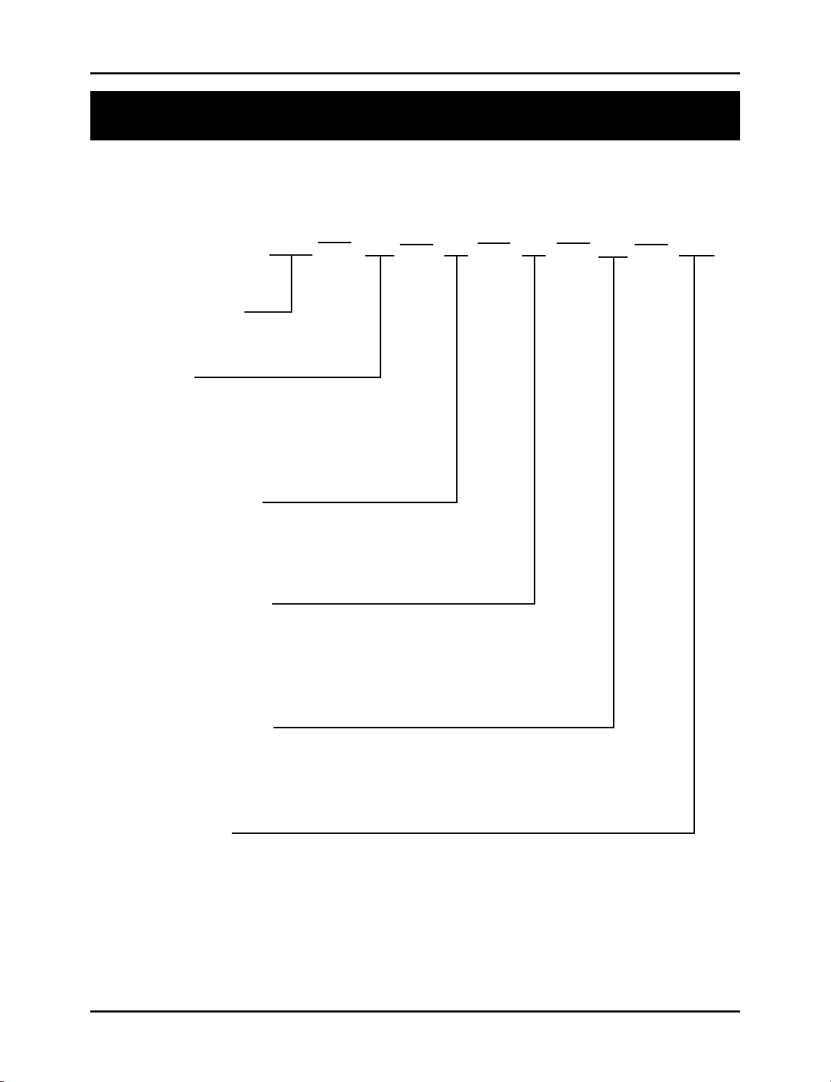
Appendix C: Catalog Numbering Sequence
Appendix C: Catalog Numbering System
The following fi gure describes the catalog numbering system for the Series 2120 Interface
Module. As shown, the module can be used with several different types of input and output
boards. The catalog number can be found on the product sticker located on the side of the
monitor.
2120 V1 K1 D1 A1 N12
Interface Module
Input Type
V1 = VP LDT
R1 = Resolver
L1 = LDT Input
Relay Output Type
K0 = without relay board
K1 = with relay outputs
Digital Output Type
D0 = without digital outputs
D1 = sinking outputs
D2 = sourcing outputs
D3 = TTL outputs
Analog Output Type
A0 = without analog outputs
A1 = standard analog outputs
Enclosure Type
N0 = no enclosure
N4 = NEMA 4 enclosure
N12 = NEMA 12 enclosure
Figure C-1 Catalog numbering system
Installation and Programming Manual
53
Page 58

Appendix D: Specifi cations
Appendix D: Specifi cations
Electromagnetic Rating: IEC 801-2, Level 3
(Electrostatic discharge requirements)
IEC 801-4, Level 3
(Electrical fast transient/ burst requirements)
Humidity: 5% to 95%, noncondensing
Memory Retention Time: Maintains programmed values for 10 years without power.
Movement Input: 85-265 VAC (rms), 12 mA maximum; optical isolated to
3200 VDC and 2250 VAC.
Analog:
Output Settings: 2 channels independently confi gurable for Voltage or
Current output.
Resolution:
Voltage Resolution Approx. 300µV
Current Resolution Approx. 0.300 µA
Update Period:
For confi gurations
without Digital Outputs: Position: 5mS
Rate: 10 mS
For confi gurations
with Digital Outputs: Position: 20 mS
Rate: 10 mS
Non Linearity:
T = 25 C: ± 915 µV
± 0.915 µA
Output Drift: Less than ±30 ppm/°C
Voltage 100 µVolt/°C typical
Current 0.10 µAmp/°C typical
Output Isolation: None
Output Loading:
Voltage ±10V into a 1KΩ load (±10mA max)
Current 0 mA to 20 mA sourcing into a 750Ω load (15V max)
54
Installation and Programming Manual
Page 59

Appendix D: Specifi cations
Power Requirements: 85-265 VAC, 50-60 Hz., internally fused at 1.5 amps.
Program Mode Input: Dry contact, open collector (drain) only; +5 VDC
maximum, current 0.2 mA.
Relay Contact Ratings: All relays are rated UL and CSA of 1/4 HP, 125-250 VAC;
8A 250 VAC, 30 VDC, shock resistant to 10 G.
RS-485 Output: Up to 115.2K baud, not less than ±1.5V into a 27 ohm load
(RS-485); not less than ±2.0V into a 50 ohm load (RS-422).
Maximum cable length of 1000' using a shielded twisted
pair cable (similar to a BELDEN 9481 cable)
RS-232 Output: Up to 115.2K baud, not less than ±5V into a 3K ohm, 2250
pF load.
Shock and Vibration: Tested up to MIL-STD 810E, method 514.4 category 10,
20-2K Hz., at 2G sine, 0.04 G
2
/Hz random and UL 491,
SA19, 10-150 Hz 10G sine.
Temperature Range:
Operating 32°F - 131°F (0°C - 55°C)
Storage 0°F - 150°F (-18°C - 66°C)
Digital:
Output Rating:
Sinking Device (option D1) 5 - 24 VDC @ 100mA max
VOL = 1.1V max
Sourcing Device (option D2) 5 - 24 VDC @ 100mA max
VOH = VIN - 1.8
TTL Device (option D3) VOH = 3.7 min @ IOH = 24mA
V
OL = .44 max @ IOL = 24mA
Input Ratings: 24VDC @ 9mA max
Low < 1.4V @ 0.5mA
High > 2.0V @ 1mA
TTL Compatible
NOTE: Digital output update time increases in analog confi guration from 100 to 125 µS
Installation and Programming Manual
55
Page 60

Glossary
Glossary
Access Code This is a four-digit number that must be entered in the Program
Mode Access function in order to put the monitor in either
program mode or supervisory mode. There are two types of access
codes: program mode and supervisory mode.
Calibration Functions A group of functions used to calibrate the monitor’s input device.
These functions can only be programmed when the monitor is in
program mode.
Controller Module This module contains a Central Processing Unit (CPU) which is
used to process data it receives from the resolver. It then shows the
position of the shut height on the monitor’s LED display.
Fault Check Relay Located on the power supply module, this relay consists of a pair
of N.O. contacts. During normal machine operation, this relay
is energized. If an error occurs during machine operation, the
controller will de-energize this relay. This relay should be wired to
the machine’s safety interlock.
LDT Module L1 This module is used with a Linear Displacement Transducer
(LDT). This module provides +24VDC to supply power to the
LDT and interface for the RS-422 output signal.
Lower Limit Relay Located on the relay output module, this relay consists of one
pair of N.O. contacts and one pair of N.C. contacts. This relay
is programmable to de-energize when the machine’s shut height
moves below the programmed lower end limit.
Power Supply Module This module supplies power to the monitor. It also contains the
fault check relay and an auxiliary input. The auxiliary input is used
for either the movement detection or position hold feature.
Program Mode A mode of operation the monitor must be in before a function can
be programmed. The Program Mode Access function is used to put
the monitor in program mode.
Recirculations The method used to improve the resolution of an LDT. The “on”
time of a pulse width output is multiplied by a specifi ed factor.
This multiplication provides more counting time for the counter,
56
Installation and Programming Manual
Page 61

Glossary
thus improving the resolution.
Relay Output Module This module contains an upper and lower limit relay. These relays
are programmable to de-energize or energize when the machine
moves outside either of the relay’s specifi ed limits.
Resolver Module This module is used with any Gemco resolver.
Supervisory Functions A group of functions hidden from normal use and intended
specifi cally for the equipment supervisor. For example, a function
is provided to change the access code which puts the monitor in
program mode. These functions can only be programmed when the
monitor is in supervisory mode.
Supervisory Mode A mode of operation the monitor must be in before a supervisory
function can be programmed. The supervisory mode access code is
used to put the monitor in supervisory mode.
Upper Limit Relay Located on the relay output module, this relay consists of one
pair of N.O. contacts and one pair of N.C. contacts. This relay is
programmable to de-energize when the machine moves above the
programmed upper end limit.
Variable Pulse Module V1 This module is used with a Linear Displacement Transducer (LDT)
that operates on variable pulses, such as Gemco’s 951 VP-1992
LDT. This module provides +24 VDC to supply power to the LDT
and interface for the RS-422 output signal.
Wire Speed The time it takes a pulse to travel the guide rail on an LDT. For
example, a LDT set to a wire speed of 9.000 microseconds has
pulses that travel its guide rail at a speed of 9.000 microseconds
per inch.
Installation and Programming Manual
57
Page 62

Index
Index
A
Analog Output 4
Auxiliary LED Function 32, 50
C
Count Direction 27
D
Decimal Location Function 31, 50
Digital Output 4
Display Power Up 25, 51
F
Faceplate 2, 5, 21
Fault Pulse Time Function 29, 51
Functions
Auxiliary LED 32, 50
Count Direction 27
Decimal Location 31, 50
Display Power Up 25, 51
Fault Pulse Time 29, 51
LDT Input Reset-to-Preset 30, 51
Lower End Limit 34, 35, 50, 55
Move Detection Time-out 33, 50
Position Hold 31, 50
Position Offset 23, 25, 28, 51
Program Mode Access 42, 43, 50, 55
Program Mode Time-out 43
Relay Override 35, 38, 51
Relay State 35, 50
Resolver Reset-to-Preset 25, 51
Scale Factor 22, 23, 51
Turns Counting 22, 23, 24
Unit of Measurement 31, 50
Upper End Limit 34, 50, 56
Wire Speed 27
Wrap Around 23, 24
G
General Hardware Components
Faceplate 2, 5, 17
Mounting Rails 9
L
LED Aux 6
Fault Check OK 5
Lower Limit 6
Movement Fault 5
Position 6
Program 5
RPM 6
Upper Limit 6
LDT Input 4
LDT Input Reset-to-Preset 30, 51
LDT Output 29
Lower End Limit Function 34, 35, 50, 55
Lower Limit Relay 34, 35, 50, 55
M
Modules
Standard
Controller 3
Power supply 3, 11
Move Detection Time-out Function 33, 50
P
Position Hold Function 31, 32, 50
Position Offset Function 23, 25, 28, 51
Program Mode Access Function
42, 43, 50, 55
Program Mode Time-out Function 43, 50
R
Relay Output Module 5, 10, 11, 55
Relay Override Function 35, 36, 51
Relay State Function 35, 50
Resolver Module 3, 12
Resolver Reset-to-Preset 25, 51
58
Installation and Programming Manual
Page 63

S
Scale Factor (300) 22, 23, 51
T
Turns Counting (301) 22, 23, 24
U
Unit of Measurement Function 29, 30, 50
Upper End Limit Function 34, 50, 56
V
Variable Pulse LDT Module 4, 12, 56
W
Index
Wire Speed Function 27, 51, 56
Wrap Around Function (308) 23, 24, 51
Installation and Programming Manual
59
Page 64

Other Products
Copyright 2005 by AMETEK AUTOMATION & PROCESS TECHNOLOGIES. All Rights Reserved. Made in the USA.
1080 N. Crooks Road, Clawson, MI 48017-1097
Phone: 248.435.0700 Toll Free: 800.635.0289
Fax: 248.435.8120 www.AMETEKAPT.com
2120.M2R
8/05.Z71
2C
 Loading...